JP6205558B2 - Game machine - Google Patents
Game machine Download PDFInfo
- Publication number
- JP6205558B2 JP6205558B2 JP2013270251A JP2013270251A JP6205558B2 JP 6205558 B2 JP6205558 B2 JP 6205558B2 JP 2013270251 A JP2013270251 A JP 2013270251A JP 2013270251 A JP2013270251 A JP 2013270251A JP 6205558 B2 JP6205558 B2 JP 6205558B2
- Authority
- JP
- Japan
- Prior art keywords
- winding
- time
- windings
- spinning
- rotating
- Prior art date
- Legal status (The legal status is an assumption and is not a legal conclusion. Google has not performed a legal analysis and makes no representation as to the accuracy of the status listed.)
- Expired - Fee Related
Links
Images


Description
この発明は、回胴とそれを回転駆動するステッピングモータを備えるスロットマシンなどの遊技機に関する。 The present invention relates to a gaming machine such as a slot machine including a rotating drum and a stepping motor that rotationally drives the rotating drum.
従来から外周面に図柄が配列された複数の回胴を備えた遊技機(回胴式遊技機、スロットマシン)が知られている。この種の遊技機は、遊技媒体(メダル)に対して一定の遊技価値を付与し、このような遊技媒体を獲得するための遊技を行うものである。また、この種の遊技機は、遊技者の回転開始操作を契機として、内部抽選を行うとともに複数の回胴の回転を開始させ、遊技者の停止操作契機として、内部抽選の結果に応じた態様で複数の回胴を停止させる制御を行っている。そして、遊技の結果は、複数の回胴が停止した状態における入賞判定ライン上に表示された図柄の組み合わせによって判定され、遊技の結果に応じてメダル等の払い出しなどが行われる。 2. Description of the Related Art Conventionally, a gaming machine (a spinning machine, slot machine) having a plurality of spinning cylinders having symbols arranged on an outer peripheral surface is known. This type of gaming machine gives a certain game value to a game medium (medal) and performs a game for acquiring such a game medium. In addition, this type of gaming machine has an internal lottery triggered by the player's rotation start operation and starts rotation of a plurality of spinning cylinders, and a mode according to the result of the internal lottery as a player's stop operation trigger. In order to stop multiple cylinders. The game result is determined by a combination of symbols displayed on the winning determination line in a state where a plurality of spinning cylinders are stopped, and medals are paid out according to the game result.
また、スロットマシンの中には、内部当選を報知する際に回胴を動かすものがある。通常、回胴はスタートスイッチの押下による遊技の開始で回転し、ストップボタンの押下で停止するものであるが、回胴による演出機能を備えるスロットマシンでは、スタートスイッチ押下からストップボタン押下までの期間、より正確に言えばスタートスイッチ押下から回胴が定常回転になるまでの期間において、各回胴を不規則に上下に動かすなどの特殊な動作を行うことで、内部当選を報知することがある。通常遊技における回胴の動きは一方向かつ一定速度の規則的なものであるから、演出による回胴の動きとは容易に区別することができる。このような回胴の動作は、回胴演出と呼ばれる。 Also, some slot machines move the spinning cylinder when notifying internal winnings. Normally, the spinning cylinder rotates at the start of the game by pressing the start switch, and stops when the stop button is pressed, but in a slot machine with a rendering function by the spinning cylinder, the period from the start switch pressing to the stop button pressing More precisely, during a period from when the start switch is pressed to when the rotating cylinder becomes a steady rotation, an internal winning may be notified by performing a special operation such as irregularly moving each rotating cylinder up and down. Since the movement of the spinning cylinder in a normal game is regular in one direction and at a constant speed, it can be easily distinguished from the movement of the spinning cylinder due to performance. Such an operation of the rotating cylinder is called a rotating effect.
遊技機の回胴を回転させるためのモータとして、固定子として4相の巻線(コイル)を備えるステッピングモータが使用されている。ステッピングモータは、回転子(ロータ)として歯車状の鉄心あるいは永久磁石を備え、固定子(ステータ)として複数の巻線(コイル)を備え、電流を流す巻線を切り替えることによって回転動作させるものである。各巻線に順番に電流を流すとモータは電流の流された巻線に従って回転し、逆の順番に電流を流すとモータは逆回転する。以下の説明において、巻線に電流を流すことを「励磁」と表記する。 As a motor for rotating a spinning cylinder of a gaming machine, a stepping motor having a four-phase winding (coil) as a stator is used. A stepping motor includes a gear-shaped iron core or permanent magnet as a rotor (rotor), a plurality of windings (coils) as a stator (stator), and is rotated by switching windings through which current flows. is there. When a current is passed through each winding in turn, the motor rotates according to the winding through which the current is passed, and when a current is passed in the reverse order, the motor rotates in the reverse direction. In the following description, flowing current through the winding is referred to as “excitation”.
図11及び図14を参照してモータを回転させるための励磁の手順について説明を加える。なお、図11及び図14の見方については、後述の図5の説明も参照されたい。 The excitation procedure for rotating the motor will be described with reference to FIGS. For the way of viewing FIGS. 11 and 14, refer to the description of FIG. 5 described later.
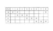
図14は、スタートスイッチの押下により遊技を開始する際における励磁の手順、すなわち通常遊技における回胴の回転のための励磁の手順を示す。図14の○印で示すように4つの巻線のうち一つ又は二つを、第4巻線から第1巻線の順番に予め定められた時間を単位として励磁する。第1巻線の励磁の次は第4巻線の励磁に戻る。図14では時間=1単位時間となっているが、例えば、1単位時間=1.5msである。通常遊技における回胴の回転は一方向かつ一定速度であるので、ストップボタンの押下により(あるいは所定時間経過したことにより)回胴が停止するまで、図14の励磁が繰り返される。 FIG. 14 shows an excitation procedure when starting a game by pressing a start switch, that is, an excitation procedure for rotating the spinning cylinder in a normal game. As indicated by the circles in FIG. 14, one or two of the four windings are excited in units of a predetermined time in the order from the fourth winding to the first winding. Next to the excitation of the first winding, the excitation returns to the excitation of the fourth winding. In FIG. 14, time = 1 unit time, but for example, 1 unit time = 1.5 ms. Since the rotation of the spinning cylinder in the normal game is unidirectional and at a constant speed, the excitation shown in FIG. 14 is repeated until the spinning cylinder is stopped by pressing the stop button (or when a predetermined time has elapsed).
図11(a)及び(b)は、回胴演出における励磁の手順を示す。図11(a)は、通常遊技における回胴の回転とは反対側へ回転させるための励磁の手順であり、図11(b)は、通常遊技における回胴の回転と同じ方向へ回転させるための励磁の手順である。図11(a)及び(b)においても○印で示すように4つの巻線のうち一つ又は二つを、第1巻線から第4巻線の順番、又は、第4巻線から第1巻線の順番に予め定められた時間を単位として励磁する。図11(a)の励磁が所定時間繰り返されると、図11(b)の励磁が所定時間繰り返される。回胴演出においてはこれらの励磁が所定回数繰り返される。図11(a)及び(b)では時間=2単位時間となっているが、例えば、2単位時間=3msである。励磁の時間が長いと回転速度は低くなる。上記例では、回胴演出時の回転速度は、通常遊技における回転速度の半分である。 FIGS. 11A and 11B show an excitation procedure in the spinning effect. FIG. 11 (a) shows an excitation procedure for rotating in the opposite direction to the rotation of the spinning cylinder in the normal game, and FIG. 11 (b) is for rotation in the same direction as the rotation of the spinning cylinder in the normal game. This is the excitation procedure. 11 (a) and 11 (b), one or two of the four windings are arranged in the order from the first winding to the fourth winding, or from the fourth winding to Excitation is performed in units of a predetermined time in the order of one winding. When the excitation shown in FIG. 11A is repeated for a predetermined time, the excitation shown in FIG. 11B is repeated for a predetermined time. In the spinning effect, these excitations are repeated a predetermined number of times. In FIGS. 11A and 11B, time = 2 unit time, but for example, 2 unit time = 3 ms. If the excitation time is long, the rotation speed becomes low. In the above example, the rotation speed during the spinning effect is half of the rotation speed in the normal game.
回胴演出における回胴の動きについて、図15を参照して説明を加える。この図はひとつの回胴についてその速度変化を測定したグラフである。 The movement of the rotating cylinder in the rotating effect will be described with reference to FIG. This figure is a graph measuring the speed change of one cylinder.
横軸は時間でありその格子のひとつの幅は200msである。図15(a)のt2’はt1’から200ms経過した時刻である。t3’、t4’についても同様である。t0’が回胴演出の開始タイミング(回胴演出を行うために巻線に電流を流すこと、励磁を開始したタイミング)である。なお、測定を開始する前(t0’以前)に回胴を測定位置に戻す処理、いわば測定の準備処理を行っている。txから始まっている動きがその処理に対応しており、これは回胴演出とは無関係である。以後、もっぱらt0’以降の動作について説明を加える。 The horizontal axis is time, and the width of one of the lattices is 200 ms. In FIG. 15A, t2 'is the time when 200 ms has elapsed from t1'. The same applies to t3 'and t4'. t0 'is the start timing of the spinning effect (the timing at which a current is passed through the winding to perform the spinning effect and the excitation is started). Before starting the measurement (before t0 '), a process for returning the rotating drum to the measurement position, that is, a preparation process for measurement, is performed. The movement starting from tx corresponds to the process, which is independent of the spinning effect. Hereinafter, only the operation after t0 'will be described.
縦軸は回胴の速度である。+方向(グラフの上方向)が通常遊技における回胴の回転方向の動きに対応し、−方向(グラフの下方向)がその反対の方向(遊技者から見て上方向)の動きに対応する。 The vertical axis represents the speed of the rotating drum. The + direction (upward on the graph) corresponds to the movement in the rotating direction of the spinning cylinder in normal games, and the-direction (downward on the graph) corresponds to the movement in the opposite direction (upward as viewed from the player). .
図15(a)からわかるように、まず図11(a)の励磁が行われ回胴は−方向へ動き、その後図11(b)の励磁が行われ+方向へ動く。このような回転方向が頻繁に切り替わる、いわば回胴が振動するような動きが回胴演出のひとつである。図の例ではその周期は約60msである。また上下がほぼ対称(グラフの+の面積と−の面積がほぼ等しい)であるので、回胴は同じ図柄を中心に振動することになる。通常遊技における回胴の動きは一方向かつ一定速度の規則的なものであるから、図15(a)に示す回胴の動きは、通常遊技の動きと容易に区別することができる。 As can be seen from FIG. 15A, first, the excitation of FIG. 11A is performed and the rotating cylinder moves in the − direction, and then the excitation of FIG. 11B is performed and moves in the + direction. Such a rotation direction is frequently switched, that is, a movement that vibrates the rotating cylinder is one of the rotating effects. In the illustrated example, the period is about 60 ms. In addition, since the top and bottom are almost symmetrical (the + area and the − area of the graph are almost equal), the rotator vibrates around the same symbol. Since the movement of the spinning cylinder in the normal game is regular in one direction and at a constant speed, the movement of the spinning cylinder shown in FIG. 15A can be easily distinguished from the movement of the normal game.
図15(a)の動きを行わせるためには、各巻線に一定時間(例えば約30ms)通常遊技とは反対の順番で各巻線に電流を流し、その後一定時間通常遊技と同じ順番で各巻線に電流を流し、そしてこれらを繰り返すようにする。巻線の切り替え時間(言い換えればひとつの巻線に電流を流す時間)により回転速度を調節することができる。上記のように、回胴演出における回転速度を通常遊技における回転速度の半分にする場合には、回胴演出における巻線の切り替え時間を通常遊技における巻線の切り替え時間の2倍にすればよい。 In order to perform the movement shown in FIG. 15A, a current is passed through each winding in an order opposite to that of the normal game for a certain period of time (for example, about 30 ms), and thereafter Current is passed through and is repeated. The rotation speed can be adjusted by changing the winding time (in other words, the time for passing a current through one winding). As described above, when the rotation speed in the spinning effect is halved in the normal game, the winding switching time in the spinning effect may be twice as long as the winding switching time in the normal game. .
上述のように制御することにより、図15(a)に示すような回胴演出を行うことができるが、特定の状況下では問題が生じることが判明した。例えば、周囲温度(気温)が比較的高い中で長時間にわたって遊技を行い、モータの発熱によりその温度が上昇したような場合、モータのトルクが低下してしまい、脱調等の不具合が発生してしまう。 By performing the control as described above, it is possible to perform a spinning effect as shown in FIG. 15A, but it has been found that a problem arises in a specific situation. For example, if a game is played for a long time at a relatively high ambient temperature (air temperature) and the temperature rises due to the heat generated by the motor, the motor torque will drop, causing problems such as step-out. End up.
図15(b)は前記不具合が生じたときのグラフを示す。図15(b)のグラフ及び符号は図15(a)と同じである。 FIG. 15B shows a graph when the above-mentioned trouble occurs. The graphs and symbols in FIG. 15B are the same as those in FIG.
図15(a)では、グラフの上下がほぼ対称であり回胴は同じ図柄を中心にきれいな正弦波を描くように振動していたが、図15(b)のグラフでは、上下対称ではなく、不規則である。図15(b)のt2’の前の時点で脱調している。遊技者からは、図15(a)の場合は回胴が振動しているように見えるが、図15(b)の場合は回胴がずるずると滑っているように見え、振動動作とは程遠い動作になってしまっている。 In FIG. 15A, the upper and lower sides of the graph are almost symmetrical, and the rotating cylinder vibrates so as to draw a clean sine wave around the same pattern, but in the graph of FIG. It is irregular. Step-out occurs at a time point before t2 'in FIG. In the case of FIG. 15 (a), the player seems to vibrate in the case of FIG. 15 (a), but in the case of FIG. 15 (b), it seems that the case is slippery and slips far from the vibration operation. It has become an operation.
モータ過熱時の対策を開示する先行技術として、上記特許文献1〜3がある。
As a prior art disclosing countermeasures when the motor is overheated, there are
特許文献1は、温度上昇時に一部の動作をやめることにより温度を下げようとするものであり、温度上昇した状態でも正常動作を行わせるものではない。
特許文献2及び特許文献3は、温度上昇時にモータの駆動電流を下げることにより温度を下げようとするものであり、温度上昇した状態でも正常動作を行わせるものではない。
また、特許文献1〜3はいずれも通常遊技の回胴の制御を開示しているが、回胴演出における回胴の制御についての記載はない。 Moreover, although patent documents 1-3 are all disclosing the control of the rotation of a normal game, there is no description about the control of the rotation in a rotation effect.
モータの発熱が原因であれば、その動作を一定時間停止すれば自然冷却により不具合は解消する。しかし、その間は回胴演出のみならず通常遊技も行えなくなる。あるいは、モータに冷却手段を設けるようにしてもよいが、これはコストの増大をもたらす。 If the cause is heat generation of the motor, the problem is solved by natural cooling if the operation is stopped for a certain period of time. However, during that time, not only the spinning performance but also normal games can no longer be performed. Alternatively, a cooling means may be provided in the motor, but this causes an increase in cost.
この発明は、回胴演出の実行に影響を与えず、しかもコストを増大させることなく、モータの発熱による回胴演出の不具合を解消することのできる遊技機を提供することを目的とする。 An object of the present invention is to provide a gaming machine that can solve the problem of the spinning effect caused by the heat generated by the motor without affecting the execution of the spinning effect and increasing the cost.
この発明は、複数の回胴を含むリールユニットと、前記複数の回胴をそれぞれ回転させる複数のモータと、前記複数の回胴の回転を開始させるためのスタートスイッチと、前記複数のモータにそれぞれ駆動信号を与えて前記複数の回胴を回転させる回胴制御手段と、前記スタートスイッチからのスタート信号に基づいて役の当否を決定する内部抽選を行う内部抽選手段とを備え、
少なくとも、前記内部抽選の結果に基づき前記回胴の動作態様により所定の報知を行う回胴演出を行う遊技機において、
前記複数のモータは、それぞれ、固定子として、少なくとも第1巻線、第2巻線、第3巻線及び第4巻線を備えるステッピングモータであり、前記回胴制御手段により前記第1巻線乃至第4巻線のうち一つ又は二つが励磁されることにより前記回胴が回転されて前記回胴演出が行われ、
前記回胴制御手段は、
前記第1巻線乃至第4巻線のうち二つを予め定められた第1時間励磁する第1ステップと、前記第1巻線乃至第4巻線のうち一つ又は二つを予め定められた第2時間順番に励磁する第2ステップとを備える予備動作処理を行い、
前記予備動作処理の後に、前記第1巻線乃至第4巻線のうち一つ又は二つを予め定められた第3時間順番に励磁することにより前記回胴演出を行い、
前記第1時間、前記第2時間及び前記第3時間について、第1時間>第2時間≧第3時間の関係が成立していることを特徴とするものである。
The present invention provides a reel unit including a plurality of spinning cylinders, a plurality of motors for rotating the plurality of spinning cylinders, a start switch for starting rotation of the plurality of spinning cylinders, and the plurality of motors, respectively. A rotation control means for rotating the plurality of rotation cylinders by giving a drive signal, and an internal lottery means for performing an internal lottery for determining whether or not a combination is based on a start signal from the start switch,
At least in a gaming machine that performs a spinning effect in which a predetermined notification is made according to the operation mode of the spinning cylinder based on the result of the internal lottery,
Each of the plurality of motors is a stepping motor including at least a first winding, a second winding, a third winding, and a fourth winding as a stator, and the first winding by the rotating cylinder control unit. Or one or two of the fourth windings are excited to rotate the rotating drum and perform the rotating drum effect,
The spinning cylinder control means includes:
A first step of exciting two of the first to fourth windings for a predetermined first time; and one or two of the first to fourth windings are predetermined. A preliminary operation process including a second step of exciting in the second time sequence,
After the preliminary operation process, performing the spinning effect by exciting one or two of the first to fourth windings in a predetermined third time sequence,
For the first time, the second time, and the third time, a relationship of first time> second time ≧ third time is established.
前記予備動作処理の前記第2ステップにおいて、前記第1ステップで励磁された前記巻線の一方を初期位置として、前記初期位置から順番に一つ又は二つの前記巻線を順番に励磁し、
前記回胴演出において、前記予備動作処理の前記第2ステップにおいて最後に励磁された前記巻線を終了位置として、前記終了位置から順番に一つ又は二つの前記巻線を順番に励磁するようにしてもよい。
In the second step of the preliminary operation process, one of the windings excited in the first step is set as an initial position, and one or two of the windings are sequentially excited from the initial position,
In the winding effect, the winding that was last excited in the second step of the preliminary operation process is set as an end position, and one or two of the windings are sequentially excited from the end position. May be.
前記回胴制御手段は、前記回胴の停止時に励磁した前記巻線の位置を停止時巻線位置として記憶し、
前記予備動作処理の前記第1ステップにおいて、前記停止時巻線位置を読み出し、読み出した前記停止時巻線位置に基づき二つの前記巻線を選択し、これらを励磁するようにしてもよい。
The rotating cylinder control means stores the position of the winding excited when the rotating cylinder is stopped as a winding position when stopped,
In the first step of the preliminary operation process, the stop winding position may be read out, and the two windings may be selected based on the read out stop winding position and excited.
この発明によれば、回胴演出に先立ち、前記第1巻線乃至第4巻線のうち二つを予め定められた第1時間励磁する第1ステップと、前記第1巻線乃至第4巻線のうち一つ又は二つを予め定められた第2時間順番に励磁する第2ステップとを備える予備動作処理を行うので、モータの発熱による回胴演出の不具合を解消でき、回胴演出を正常に行うことができる。 According to the present invention, prior to the winding effect, the first step of exciting two of the first winding to the fourth winding for a predetermined first time, and the first winding to the fourth winding. Since the preliminary operation process including the second step of exciting one or two of the lines in a predetermined second time order is performed, the problem of the spinning effect due to the heat generation of the motor can be eliminated, and the spinning effect is Can be done normally.
図1は前扉を閉めた状態を示すスロットマシンの正面図、図2は前扉を180度開いた状態を示すスロットマシンの正面図を示す。 FIG. 1 is a front view of the slot machine with the front door closed, and FIG. 2 is a front view of the slot machine with the front door opened 180 degrees.
図1及び図2中、100はスロットマシンを示すもので、このスロットマシン100は、図1に示すように、スロットマシン本体120と、このスロットマシン本体120の前面片側にヒンジ等により開閉可能に取り付けられた前扉130とを備えている。前記前扉130の前面には、図1に示すように、ほぼ中央にゲーム表示部131を設け、ゲーム表示部131の右下隅部に、遊技者がメダルを投入するためのメダル投入口132を設け、メダル投入口132の下側には、メダル投入口132から投入され、詰まってしまったメダルをスロットマシン100外に強制的に排出するためのリジェクトボタン133が設けられている。
1 and 2,
また、前記ゲーム表示部131の左下方には、ゲームを開始するためのスタートスイッチ134を設けてあり、3つの回胴(第1回胴40a〜第3回胴40c)のそれぞれに対応して3つのストップボタン140を設けてある。前扉の下端部中央には、メダルの払出し口135を設けてある。前記ゲーム表示部131の右側には、液晶表示装置LCDが設けてある。
Further, a
スロットマシン本体120の内部には、図2に示すように、その内底面に固定され、内部に複数のメダルを貯留して、貯留したメダルを前扉130の前面に設けた払出し口135に1枚ずつ払い出すためのホッパ装置121が設置されている。このホッパ装置121の上部には、上方に向けて開口し、内部に複数のメダルを貯留するホッパタンク122を備えている。スロットマシン本体120の内部には、前扉130を閉めたときにゲーム表示部131が来る位置に三個の回胴40a、40b、40cからなるリールユニット203が設置されている。リールユニット203は、外周面に複数種類の図柄が配列されている3つの回胴40a、40b、40cを備えている。ゲーム表示部131には開口部が設けられていて、それを通して遊技者が前記リールユニット203の各回胴40a、40b、40cの図柄を見ることができるようになっている。ホッパ装置121の上側のリールユニット203との間には電源部205が設けられている。
As shown in FIG. 2, the slot machine
前記前扉130の裏面には、図2に示すように、メダル(コイン)セレクタ1が、前扉130の前面に設けられたメダル投入口132の裏側に取り付けられている。このメダルセレクタ1は、メダル投入口132から投入されたメダルの通過を検出しながら、当該メダルをホッパ装置121に向かって転動させ、外径が所定寸法と違う異径メダルや、鉄又は鉄合金で作製された不正メダルを選別して排除するとともに、1ゲームあたりに投入可能な所定枚数以上のメダルを選別して排除するための装置である。
As shown in FIG. 2, the medal (coin)
また、メダルセレクタ1の下側には、図2に示すように、その下部側を覆って前扉130の払出し口135に連通する導出路136が設けられている。メダルセレクタ1により振り分けられたメダルは、この導出路136を介して払出し口135から遊技者に返却される。
Further, as shown in FIG. 2, a lead-out
図3は発明の実施の形態に係るスロットマシン100の機能ブロック図を示す。
この図において電源系統についての表示は省略されている。図示しないが、スロットマシンは商用電源(AC100V)から直流電源(+5Vなど)を発生するための電源部を備える。
FIG. 3 shows a functional block diagram of the
In this figure, the display about the power supply system is omitted. Although not shown, the slot machine includes a power supply unit for generating a DC power supply (+5 V or the like) from a commercial power supply (AC 100 V).
スロットマシン100は、その主要な処理装置としてメイン基板(処理部)10とこれからコマンドを受けて動作するサブ基板20とを備える。なお、少なくともメイン基板10は、外部から接触不能となるようにケース内部に収容され、これら基板を取り外す際に痕跡が残るように封印処理が施されている。
The
メイン基板10は、遊技者の操作を受けて内部抽選を行ったり、回胴40a、40b、40cの回転・停止やメダルの払い出しなどの処理を行うためのものである。メイン基板10は、予め設定されたプログラムに従って制御動作を行うCPUと、前記プログラムを記憶する記憶手段であるROM及び処理結果などを一時的に記憶するRAMを含む。
The
サブ基板20は、メイン基板10からコマンド信号を受けて内部抽選の結果を報知したり各種演出を行うためのものである。サブ基板20は、前記コマンド信号に応じた予め設定されたプログラムに従って制御動作を行うCPUと、前記プログラムを記憶する記憶手段であるROM及び処理結果などを一時的に記憶するRAMを含む。コマンドの流れはメイン基板10からサブ基板20への一方のみであり、逆にサブ基板20からメイン基板10へコマンド等が出されることはない。
The
メイン基板10には、ベットスイッチBET、スタートスイッチ134、ストップボタン140、リールユニット203の回胴位置検出器159とステッピングモータ155、ホッパ駆動部80、ホッパ81及びホッパ81から払い出されたメダルの枚数を数えるためのメダル検出部82(これらは前述のホッパ装置121を構成する)が接続されている。サブ基板20には液晶表示装置の制御用の液晶制御基板200、スピーカ基板201、LED基板202などの周辺基板(ローカル基板)が接続されている。
The
メイン基板10には、さらに、メダルセレクタ1のメダルセンサS1及びS2が接続されている。
Further, medal sensors S1 and S2 of the
メダルセレクタ1には、メダルを計数するためのメダルセンサS1及びS2が設けられている。メダルセンサS1及びS2は、メダルセレクタ1に設けられた図示しないメダル通路の下流側(出口近傍)に設けられている(メダル通路の上流側はメダル投入口132に連通している)。2つのメダルセンサS1とS2は、メダルの進行方向に沿って所定間隔を空けて並べて設けられている。メダルセンサS1、S2は、例えば、互いに対向した発光部と受光部とを有して断面コ字状に形成され、その検出光軸をメダル通路内に上方から臨ませて位置するフォトインタラプタである。各フォトインタラプタにより、途中で阻止されずに送られてきたメダルの通過が検出される。なお、フォトインタラプタを2つ隣接させたのは、メダル枚数を検出するだけでなく、メダルの通過が正常か否かを監視するためである。すなわち、フォトインタラプタを2つ隣接させて設けることにより、メダルの通過速度や通過方向を検出することができ、これによりメダル枚数だけでなく、逆方向に移動する不正行為を感知することができる。
The
ホッパ駆動部80は、ホッパ81を回転駆動して、メイン基板10によって指示された払出数のメダルを払い出す動作を行う。遊技機は、メダルを1枚払い出す毎に作動するメダル検出部82を備えており、メイン基板10は、メダル検出部82からの入力信号に基づいてホッパ81から実際に払い出されたメダルの数を管理することができる。
The
投入受付部1050は、メダルセレクタ1のメダルセンサS1とS2の出力を受け、遊技毎にメダルの投入を受け付けて、規定投入数に相当するメダルが投入されたことに基づいて、スタートスイッチ134に対する第1回胴40a〜第3回胴40cの回転開始操作を許可する処理を行う。なお、スタートスイッチ134の押下操作が、第1回胴40a〜第3回胴40cの回転を開始させる契機となっているとともに、内部抽選を実行する契機となっている。また、遊技状態に応じて規定投入数を設定し、通常状態及びボーナス成立状態では規定投入数を3枚に設定し、ボーナス状態では規定投入数を1枚に設定する。
The
メダルが投入されると、遊技状態に応じた規定投入数を限度として、投入されたメダルを投入状態に設定する。あるいは、遊技機にメダルがクレジットされた状態で、ベットスイッチBETが押下されると、遊技状態に応じた規定投入数を限度して、クレジットされたメダルを投入状態に設定する。メダルの投入を受け付けるかどうかは、メイン基板10が制御する。メダルの投入を受け付ける状態になっていないときは(許可されていないときは)、メダルを投入してもメダルセンサS1、S2でカウントされず、そのまま返却される。同様に、メイン基板10はベットスイッチBETの有効/無効を制御する。ベットスイッチBETが有効になっていないときは(許可されていないときは)、ベットスイッチBETを押下しても、それは無視される。
When medals are inserted, the inserted medals are set to the inserted state up to a specified number of insertions according to the gaming state. Alternatively, when the bet switch BET is pressed in a state where medals have been credited to the gaming machine, the credited medals are set to the inserted state by limiting the prescribed number of insertions according to the gaming state. The
メイン基板10は、乱数発生手段1100を内蔵する。乱数発生手段1100は、抽選用の乱数値を発生させる手段である。乱数値は、例えば、インクリメントカウンタ(所定のカウント範囲を循環するように数値をカウントするカウンタ)のカウント値に基づいて発生させることができる。なお本発明の実施の形態において「乱数値」には、数学的な意味でランダムに発生する値のみならず、その発生自体は規則的であっても、その取得タイミング等が不規則であるために実質的に乱数として機能しうる値も含まれる。
The
内部抽選手段1200は、遊技者がスタートスイッチ134からのスタート信号に基づいて、役の当否を決定する内部抽選を行う。すなわち、メイン基板10のメモリ(図示せず)に記憶されている抽選テーブル(図示せず)を選択する抽選テーブル選択処理、乱数発生手段1100から得た乱数の当選を判定する乱数判定処理、当選の判定結果で大当たりなどに当選したときにその旨のフラグを設定する抽選フラグ設定処理などを行う。
The internal lottery means 1200 performs an internal lottery in which the player determines whether or not the winning combination is based on a start signal from the
抽選テーブル選択処理では、図示しない記憶手段(ROM)に格納されている複数の抽選テーブル(図示せず)のうち、いずれの抽選テーブルを用いて内部抽選を行うかを決定する。抽選テーブルでは、複数の乱数値(例えば、0〜65535の65536個の乱数値)のそれぞれに対して、リプレイ、小役(ベル、チェリー)、レギュラーボーナス(RB:ボーナス)、及びビッグボーナス(BB:ボーナス)などの各種の役が対応づけられている。また、遊技状態として、通常状態、ボーナス成立状態、及びボーナス状態が設定可能とされ、さらにリプレイの抽選状態として、リプレイ無抽選状態、リプレイ低確率状態、リプレイ高確率状態が設定可能とされる。 In the lottery table selection process, a lottery table (not shown) stored in a storage unit (ROM) (not shown) is used to determine which lottery table is used for internal lottery. In the lottery table, for each of a plurality of random values (for example, 65536 random values from 0 to 65535), replay, small role (bell, cherry), regular bonus (RB: bonus), and big bonus (BB :), etc., are associated with each other. In addition, a normal state, a bonus establishment state, and a bonus state can be set as the gaming state, and a replay lottery state, a replay low probability state, and a replay high probability state can be set as the replay lottery state.
乱数判定処理では、スタートスイッチ134からのスタート信号に基づいて、遊技毎に前記乱数発生手段(図示せず)から乱数値(抽選用乱数)を取得し、取得した乱数値について前記抽選テーブルを参照して役に当選したか否かを判定する。
In the random number determination process, a random value (lottery random number) is acquired from the random number generation means (not shown) for each game based on a start signal from the
抽選フラグ設定処理では、乱数判定処理の結果に基づいて、当選したと判定された役の抽選フラグを非当選状態(第1のフラグ状態、オフ状態)から当選状態(第2のフラグ状態、オン状態)に設定する。2種類以上の役が重複して当選した場合には、重複して当選した2種類以上の役のそれぞれに対応する抽選フラグが当選状態に設定される。抽選フラグの設定情報は、記憶手段(RAM)に格納される。 In the lottery flag setting process, the lottery flag of the winning combination determined to be won based on the result of the random number determination process is changed from the non-winning state (first flag state, off state) to the winning state (second flag state, on Status). When two or more types of winning combinations are won, a lottery flag corresponding to each of the two or more types of winning winning combinations is set to the winning state. The lottery flag setting information is stored in storage means (RAM).
入賞するまで次回以降の遊技に当選状態を持ち越し可能な抽選フラグ(持越可能フラグ)と、入賞の如何に関わらず次回以降の遊技に当選状態を持ち越さずに非当選状態にリセットされる抽選フラグ(持越不可フラグ)とが用意されていることがある。この場合、前者の持越可能フラグが対応づけられる役としては、レギュラーボーナス(RB)及びビッグボーナス(BB)があり、それ以外の役(例えば、小役、リプレイ)は後者の持越不可フラグに対応づけられている。すなわち抽選フラグ設定処理では、内部抽選でレギュラーボーナスに当選すると、レギュラーボーナスの抽選フラグの当選状態を、レギュラーボーナスが入賞するまで持ち越す処理を行い、内部抽選でビッグボーナスに当選すると、ビッグボーナスの抽選フラグの当選状態を、ビッグボーナスが入賞するまで持ち越す処理を行う。このときメイン基板10は、内部抽選機能により、レギュラーボーナスやビッグボーナスの抽選フラグの当選状態が持ち越されている遊技でも、レギュラーボーナス及びビッグボーナス以外の役(小役及びリプレイ)についての当否を決定する内部抽選を行っている。すなわち抽選フラグ設定処理では、レギュラーボーナスの抽選フラグの当選状態が持ち越されている遊技において、内部抽選で小役あるいはリプレイが当選した場合には、既に当選しているレギュラーボーナスの抽選フラグと内部抽選で当選した小役あるいはリプレイの抽選フラグとからなる2種類以上の役に対応する抽選フラグを当選状態に設定し、ビッグボーナスの抽選フラグの当選状態が持ち越されている遊技において、内部抽選で小役あるいはリプレイが当選した場合には、既に当選しているビッグボーナスの抽選フラグと内部抽選で当選した小役あるいはリプレイの抽選フラグとからなる2種類以上の役に対応する抽選フラグを当選状態に設定する。
A lottery flag (possible carryover flag) that can carry over the winning state for the next game until winning, and a lottery flag that is reset to the non-winning state without bringing the winning state to the next game regardless of winning Carry-over impossible flag) may be provided. In this case, there are a regular bonus (RB) and a big bonus (BB) as a combination to which the former carry-over possible flag is associated, and other combinations (for example, small role, replay) correspond to the latter carry-over impossible flag. It is attached. In other words, in the lottery flag setting process, when a regular bonus is won by internal lottery, the winning state of the regular bonus lottery flag is carried over until the regular bonus is won, and when a big bonus is won by internal lottery, A process of carrying over the winning state of the flag until the big bonus is won is performed. At this time, the
リプレイ処理手段1600は、所定条件下で内部抽選におけるリプレイの当選確率を変動させる制御を行うことがある。リプレイ処理手段1600については、後に再度説明を加える。リプレイの抽選状態として、リプレイが内部抽選の対象から除外されるリプレイ無抽選状態、リプレイの当選確率が約1/7.3に設定されるリプレイ低確率状態、及びリプレイの当選確率が約1/6に設定されるリプレイ高確率状態という複数種類の抽選状態を設定可能とされている。リプレイの抽選状態を変化させることにより、内部抽選におけるリプレイの当選確率を変動させる。
The
回胴制御手段1300は、遊技者がスタートスイッチ134の押下操作(回転開始操作)によるスタート信号に基づいて、第1回胴40a〜第3回胴40cをステッピングモータにより回転駆動して、第1回胴40a〜第3回胴40cの回転速度が所定速度(約80rpm:1分間あたり約80回転となる回転速度)に達した状態において回転中の回胴にそれぞれ対応する3つのストップボタン140の押下操作(停止操作)を許可する制御を行うとともに、ステッピングモータにより回転駆動されている第1回胴40a〜第3回胴40cを抽選フラグの設定状態(内部抽選の結果)に応じて停止させる制御を行う。
The spinning cylinder control means 1300 drives the
また、回胴制御手段1300は、3つのストップボタン140に対する押下操作(停止操作)が許可(有効化)された状態において、遊技者が3つのストップボタン140を押下することにより、その回胴停止信号に基づいて、リールユニット203のステッピングモータへの駆動パルス(モータ駆動信号)の供給を停止することにより、第1回胴40a〜第3回胴40cの各回胴を停止させる制御を行う。
In addition, when the player presses the three
すなわち、回胴制御手段1300は、3つのストップボタン140の各ボタンが押下される毎に、第1回胴40a〜第3回胴40cのうち押下されたボタンに対応する回胴の停止位置を決定して、決定された停止位置で回胴を停止させる制御を行っている。具体的には、記憶手段(ROM)に記憶されている停止制御テーブル(図示せず)を参照して3つのストップボタンの押下タイミングや押下順序等(停止操作の態様)に応じた第1回胴40a〜第3回胴40cの停止位置を決定し、決定された停止位置で第1回胴40a〜第3回胴40cを停止させる制御を行う。
That is, each time the three
ここで停止制御テーブルでは、ストップボタン140の作動時点における第1回胴40a〜第3回胴40cの位置(押下検出位置)と、第1回胴40a〜第3回胴40cの実際の停止位置(又は押下検出位置からの滑りコマ数)との対応関係が設定されている。抽選フラグの設定状態に応じて、第1回胴40a〜第3回胴40cの停止位置を定めるための停止制御テーブルが用意されることもある。
Here, in the stop control table, the positions of the
遊技機では、リールユニット203がフォトセンサからなるリールインデックス(図7の遮蔽板160)を備えており、回胴制御手段1300は、回胴が1回転する毎にリールインデックスで検出される基準位置信号に基づいて、回胴の基準位置(リールインデックスによって検出されるコマ)からの回転角度(ステップモータの回転軸の回転ステップ数)を求めることによって、現在の回胴の回転状態を監視することができるようになっている。すなわち、メイン基板10は、ストップボタン140の作動時における回胴の位置を、回胴の基準位置からの回転角度を求めることにより得ることができる。
In the gaming machine, the
回胴制御手段1300は、いわゆる引き込み処理と蹴飛ばし処理とを回胴を停止させる制御として行っている。引き込み処理とは、抽選フラグが当選状態に設定された役に対応する図柄が有効な入賞判定ライン上に停止するように(当選した役を入賞させることができるように)回胴を停止させる制御処理である。一方蹴飛ばし処理とは、抽選フラグが非当選状態に設定された役に対応する図柄が有効な入賞判定ライン上に停止しないように(当選していない役を入賞させることができないように)回胴を停止させる制御処理である。すなわち本発明の実施の形態の遊技機では、上記引き込み処理及び蹴飛ばし処理を実現させるべく、抽選フラグの設定状態、ストップボタン140の押下タイミング、押下順序、既に停止している回胴の停止位置(表示図柄の種類)などに応じて各回胴の停止位置が変化するように停止制御テーブルが設定されている。このように、メイン基板10は、抽選フラグが当選状態に設定された役の図柄を入賞の形態で停止可能にし、一方で抽選フラグが非当選状態に設定された役の図柄が入賞の形態で停止しないように第1回胴40a〜第3回胴40cを停止させる制御を行っている。
The spinning
本発明の実施の形態の遊技機では、第1回胴40a〜第3回胴40cが、ストップボタン140が押下された時点から190ms以内に、押下されたストップボタンに対応する回転中の回胴を停止させる制御状態に設定されている。すなわち回転している各回胴の停止位置を決めるための停止制御テーブルでは、ストップボタン140の押下時点から各回胴が停止するまでに要するコマ数が0コマ〜4コマの範囲(所定の引き込み範囲)で設定されている。
In the gaming machine according to the embodiment of the present invention, the first to the
回胴制御手段1300は、回胴演出に係る制御も行う。スロットマシンの中には、内部当選を報知する際に回胴を動かすものがある。通常、回胴はスタートスイッチの押下による遊技の開始で回転し、ストップボタンの押下で停止するものであるが、回胴による演出機能を備えるスロットマシンでは、スタートスイッチ押下からストップボタン押下までの期間、より正確に言えばスタートスイッチ押下から回胴が遊技者による停止操作が可能になるまでの期間において、各回胴を不規則に上下に動かすなどの特殊な動作を行うことで、内部当選を報知することがある(通常遊技における回胴の動きは一方向かつ一定速度の規則的なものであるから、演出による回胴の動きとは容易に区別することができる)。このような回胴の動作は、回胴演出と呼ばれる。なお、回胴演出においても遊技者のストップボタンの押下操作を有効とし、演出中の回胴が一時停止(擬似停止)するという動作が可能なこともあり、これも回胴演出に含まれる。 The rotation control means 1300 also performs control related to the rotation effect. Some slot machines move the spinning cylinder when notifying internal winnings. Normally, the spinning cylinder rotates at the start of the game by pressing the start switch, and stops when the stop button is pressed, but in a slot machine with a rendering function by the spinning cylinder, the period from the start switch pressing to the stop button pressing More precisely, during the period from when the start switch is pressed to when the spinning cylinder can be stopped by the player, the internal winnings are notified by performing special actions such as irregularly moving the spinning cylinder up and down. (Since the movement of the spinning cylinder in a normal game is regular in one direction and at a constant speed, it can be easily distinguished from the movement of the spinning cylinder due to performance). Such an operation of the rotating cylinder is called a rotating effect. It should be noted that, even in the spinning effect, the player can perform an operation of making the push operation of the stop button effective and temporarily stopping (pseudo-stopping) the spinning cylinder being produced, which is also included in the spinning effect.
なお、全ての回胴が停止した後から次回遊技に係るメダル投入受け付け開始までの間に上記回胴演出が行われるようにすることもできる。 It should be noted that the above-mentioned spinning effect may be performed after all the spinning cylinders have been stopped and before the medal insertion acceptance start relating to the next game.
擬似停止操作の際は入賞判定を行わないと上述したが、これには限定されず、回胴演出の際にも入賞判定を行うようにしてもよい。例えば、擬似停止時に目押しによって所定の図柄組み合わせ(例えば「7・7・7」)を揃えることができた場合に、いわゆるAT(当選役に対応した図柄組み合わせのナビあるいは押し順のナビ)などの特典を遊技者に与えるようにしてもよい。このようにすることにより、回胴演出中において擬似停止を行う動機付けを遊技者に与えることができ、遊技者にスムーズに擬似遊技(擬似停止操作)を行わせることができるという効果が生じる。これは、特に回胴演出に制限時間(回胴演出開始時にセットされ、タイムアップで回胴演出が終了して定常回転へ向かうシーケンスが開始されるといった場合の制限時間)を設けた場合に好適である。 Although it has been described above that the winning determination is not performed in the pseudo stop operation, the present invention is not limited to this, and the winning determination may be performed also in the spinning effect. For example, when a predetermined symbol combination (for example, “7, 7, 7”) can be aligned by pressing at the time of a pseudo stop, so-called AT (navigation of symbol combination corresponding to winning combination or navigation in pushing order), etc. May be given to the player. By doing so, it is possible to give the player motivation to perform a pseudo stop during the spinning effect, and to cause the player to smoothly perform the pseudo game (pseudo stop operation). This is particularly suitable when a time limit is set for the revolving effect (a time limit that is set when the revolving effect is started, and when the time is up, the revolving effect ends and the sequence toward steady rotation starts). It is.
上述の回胴演出が終了すると、その直後に通常の方向の定常回転を行わせる処理(シーケンス)が開始される。 When the above-mentioned spinning effect is completed, a process (sequence) for performing steady rotation in the normal direction is started immediately after that.
入賞判定手段1400は、第1回胴40a〜第3回胴40cの停止態様に基づいて、役が入賞したか否かを判定する処理を行う。具体的には、記憶手段(ROM)に記憶されている入賞判定テーブルを参照しながら、第1回胴40a〜第3回胴40cの全てが停止した時点で入賞判定ライン上に表示されている図柄組み合わせが、予め定められた役の入賞の形態であるか否かを判定する。
The winning determination means 1400 performs a process of determining whether or not a winning combination has been won based on the stopping modes of the first to
入賞判定手段1400は、その判定結果に基づいて、入賞時処理を実行する。入賞時処理としては、例えば、小役が入賞した場合にはホッパ81を駆動してメダルの払出制御処理が行われるか、あるいはクレジットの増加され(規定の最大枚数例えば50枚まで増加され、それを超えた分だけ実際にメダル払い出される)、リプレイが入賞した場合にはリプレイ処理が行われ、ビッグボーナスやレギュラーボーナスが入賞した場合には遊技状態を移行させる遊技状態移行制御処理が行われる。
The winning determination means 1400 executes a winning process based on the determination result. As a process at the time of winning a prize, for example, when a small role wins, the
払出制御手段1500は、遊技結果に応じたメダルの払い出しに関する払出制御処理を行う。具体的には、小役が入賞した場合に、役毎に予め定められている配当に基づいて遊技におけるメダルの払出数を決定し、決定された払出数に相当するメダルを、ホッパ駆動部80でホッパ81を駆動して払い出させる。この際に、ホッパ81に内蔵される図示しないモータに電流が流れることになる。
The payout control means 1500 performs payout control processing relating to the payout of medals according to the game result. Specifically, when a small combination wins, the number of medals to be paid out in the game is determined based on a payout predetermined for each combination, and the medals corresponding to the determined number of payouts are determined by the
メダルのクレジット(内部貯留)が許可されている場合には、ホッパ81によって実際にメダルの払い出しを行う代わりに、記憶手段(RAM)のクレジット記憶領域(図示省略)に記憶されているクレジット数(クレジットされたメダルの数)に対して払出数を加算するクレジット加算処理を行って仮想的にメダルを払い出す処理を行う。
When medal credits (internal storage) are permitted, instead of actually paying out medals by the
リプレイ処理手段1600は、リプレイが入賞した場合に、次回の遊技に関して遊技者の所有するメダルの投入を要さずに前回の遊技と同じ準備状態に設定するリプレイ処理(再遊技処理)を行う。リプレイが入賞した場合には、遊技者の手持ちのメダル(クレジットメダルを含む)を使わずに前回の遊技と同じ規定投入数のメダルが自動的に投入状態に設定される自動投入処理が行われ、遊技機が前回の遊技と同じ入賞判定ラインを有効化した状態で次回の遊技における回転開始操作(遊技者によるスタートスイッチ134の押下操作)を待機する状態に設定される。
When the replay is won, the replay processing means 1600 performs a replay process (regame process) for setting the same preparatory state as the previous game without requiring insertion of medals owned by the player for the next game. When a replay wins, an automatic insertion process is performed in which the same number of medals as the previous game is automatically set to the insertion state without using the player's own medals (including credit medals). The game machine is set in a state of waiting for a rotation start operation (pressing operation of the
また、メイン基板10は、通常状態、ボーナス成立状態、及びボーナス状態の間で遊技状態を移行させる制御を行うことがある(遊技状態移行制御機能)。遊技状態の移行条件は、1の条件が定められていてもよいし、複数の条件が定められていてもよい。複数の条件が定められている場合には、複数の条件のうち1の条件が成立したこと、あるいは複数の条件の全てが成立したことに基づいて、遊技状態を他の遊技状態へ移行させることができる。
Further, the
通常状態は、複数種類の遊技状態の中で初期状態に相当する遊技状態で、通常状態からはボーナス成立状態への移行が可能となっている。ボーナス成立状態は、内部抽選でビッグボーナスあるいはレギュラーボーナスに当選したことを契機として移行する遊技状態である。ボーナス成立状態では、通常状態における内部抽選でビッグボーナスが当選した場合、ビッグボーナスが入賞するまでビッグボーナスに対応する抽選フラグが当選状態に維持され、通常状態における内部抽選でレギュラーボーナスが当選した場合、レギュラーボーナスが入賞するまでレギュラーボーナスに対応する抽選フラグが当選状態に維持される。ボーナス状態では、ボーナス遊技によって払い出されたメダルの合計数により終了条件が成立したか否かを判断し、入賞したボーナスの種類に応じて予め定められた払出上限数を超えるメダルが払い出されると、ボーナス状態を終了させて、遊技状態を通常状態へ復帰させる。 The normal state is a game state corresponding to the initial state among a plurality of types of game states, and a transition from the normal state to the bonus establishment state is possible. The bonus establishment state is a gaming state that shifts when a big bonus or a regular bonus is won in the internal lottery. In the bonus establishment state, when the big bonus is won in the internal lottery in the normal state, the lottery flag corresponding to the big bonus is maintained in the winning state until the big bonus is won, and the regular bonus is won in the internal lottery in the normal state Until the regular bonus is won, the lottery flag corresponding to the regular bonus is maintained in the winning state. In the bonus state, it is determined whether or not the end condition is satisfied based on the total number of medals paid out by the bonus game, and medals exceeding a predetermined payout limit number are paid out according to the type of bonus won. The bonus state is terminated and the gaming state is returned to the normal state.
リールユニット203は、3つの回胴40a〜40cを備えるが、3つの回胴40a〜40cそれぞれにひとつずつステッピングモータ155a〜155cが取り付けられている。ステッピングモータ155a〜155cは、回転子(ロータ)として歯車状の鉄心あるいは永久磁石を備え、固定子(ステータ)として複数の巻線(コイル)を備え、電流を流す巻線を切り替えることによって回転動作させるものである。すなわち、固定子の巻線に電流を流して磁力を発生させ、回転子を引きつけることで回転するものである。回転軸を指定された角度で停止させることが可能なことから、スロットマシンの回胴の回転駆動に使用されている。相(巻線)の数として、例えば、2つ(二相)、4つ(4相)、5つ(5相)のものもある。
The
また、ステッピングモータには、ユニポーラ型とバイポーラ型がある。 Stepping motors include unipolar and bipolar types.
ユニポーラ型とは、センタタップの設けられた巻線を備えるもので、ひとつの巻線に対し常に一定方向に電流を流す方式(ユニポーラ駆動)に適するものである。この駆動方式は、駆動回路がシンプルになるというメリットがあるが、反面、巻線の利用効率が悪く(下記のバイポーラ駆動に対して1/2)、低速回転時の出力トルクが低くなるというデメリットがある。 The unipolar type is provided with a winding provided with a center tap, and is suitable for a method in which a current is always supplied to one winding in a fixed direction (unipolar driving). This drive system has the advantage that the drive circuit is simple, but on the other hand, the use efficiency of the winding is bad (1/2 compared to the bipolar drive below) and the output torque at low speed is low. There is.
バイポーラ型とは、センタタップのない通常の巻線を備え、ひとつの巻線に対し双方向に電流を流す方式(バイポーラ駆動)に適するものである。この駆動方式は、駆動回路が複雑になるというデメリットがあるが、巻線の利用効率がよく、低速回転時の出力トルクは高くなるというメリットがある。 The bipolar type is suitable for a system (bipolar drive) in which a normal winding without a center tap is provided and current is bidirectionally supplied to one winding. This driving method has a demerit that the driving circuit becomes complicated, but has an advantage that the use efficiency of the winding is good and the output torque at the time of low-speed rotation becomes high.
本発明の実施の形態は、ユニポーラ型とバイポーラ型のいずれのステッピングモータにも適用できる。 The embodiment of the present invention can be applied to both unipolar and bipolar stepping motors.
ステッピングモータは、各相の巻線への電流の与え方を変えることにより、特性を変えることができる(励磁モードが変わる)。二相型については次の通りである。 The stepping motor can change its characteristics (excitation mode changes) by changing the way of applying current to the windings of each phase. The two-phase type is as follows.
・一相励磁
常に巻線一相のみに電流を流す。位置決め精度は良い。
• Single-phase excitation Always allow current to flow through only one phase of the winding. Positioning accuracy is good.
・二相励磁
二相に電流を流す。一相励磁の約2倍の出力トルクが得られる。位置決め精度は良く、停止したときの静止トルクが大きいため、停止位置を確実に保持できる。
・ Two-phase excitation
Current flows in two phases. An output torque approximately twice that of single-phase excitation can be obtained. The positioning accuracy is good and the stationary torque is large when stopped, so that the stop position can be held reliably.
・一−二相励磁
一相と二相を交互に切り替えて電流を流す。一相励磁・二相励磁の場合のステップ角度の半分にすることができるので、滑らかな回転を得られる。
・ One-two-phase excitation
A current is passed by alternately switching between one phase and two phases. Since the step angle can be halved in the case of one-phase excitation and two-phase excitation, smooth rotation can be obtained.
スロットマシンでは、例えば、基本ステップ角度1.43度の4相(巻線)のステッピングモータを使用し、パルスの出力方法として一−二相励磁を採用している。 In the slot machine, for example, a four-phase (winding) stepping motor having a basic step angle of 1.43 degrees is used, and one-two-phase excitation is adopted as a pulse output method.
図4は、スロットマシンのステッピングモータ155の駆動回路のブロック図である。なお、図4では、各回胴の位置を検出するためのインデックスなど要素は省略している。
FIG. 4 is a block diagram of a drive circuit of the stepping
同図において、1310−1〜3はステッピングモータ155a〜155cのA相の巻線とB相の巻線のオンオフ(電流を流すかどうか)を切り替える駆動回路である。1320−1〜3は、駆動回路1310−1〜3の出力に従いステッピングモータ155a〜155cのA相の巻線とB相の巻線へ電流を流す励磁回路である。ステッピングモータ155aのA相の巻線を符号155a−Aで示し、B相の巻線の符号155a−Bで示している。ステッピングモータ155bと155cのA相の巻線とB相の巻線の表示は省略している。
In the figure, reference numerals 1310-1 to 1310-3 denote drive circuits for switching on and off (whether or not current flows) of the A-phase winding and the B-phase winding of the stepping
A相の巻線は、Aと/Aの2つの巻線を含む。B相の巻線は、Bと/Bの2種類の巻線を含む。A相の巻線とB相の巻線は、例えば、A、B、/A、/B、・・・のように交互に配置されている。A→B→/A→/B→・・・の順に励磁するとモータは一方へ回転し、/B→/A→B→A→・・・の順に励磁すると逆回転を行う。各相の励磁を切り替える間隔を短くすればモータは速く回り、間隔を長くすると遅く回る。ここで励磁する巻線を切り替えずに同じステータに電流を流し続けると、ロータが同じステータの位置に固定され、モータが現在の位置を保持しつづけることになる。 The A-phase winding includes two windings, A and / A. The B-phase winding includes two types of windings B and / B. The A-phase winding and the B-phase winding are alternately arranged, for example, A, B, / A, / B,. When excited in the order of A → B → / A → / B →..., The motor rotates in one direction, and when excited in the order of / B → / A → B → A →. If the interval for switching the excitation of each phase is shortened, the motor rotates faster, and if the interval is increased, the motor rotates slower. If the current continues to flow through the same stator without switching the exciting winding here, the rotor is fixed at the same stator position, and the motor keeps the current position.
図5は、スロットマシンのステッピングモータの駆動方法の説明図である。同図は一−二相励磁の例を示している。同図の表の○は巻線に電流を流していることを示す。同図の表のステップ1、2、・・・、8の順番で巻線に電流を流すとモータは回転し、逆の順番にするとモータは逆回転する。
FIG. 5 is an explanatory diagram of a driving method of the stepping motor of the slot machine. The figure shows an example of one-two-phase excitation. A circle in the table indicates that a current is flowing through the winding. When the current is passed through the windings in the order of
次に、回胴(リール)の具体的構成について説明を加える。 Next, a specific configuration of the rotating drum (reel) will be described.
図6(a)はリールユニット203の正面図、図6(b)は同左側面図である。
6A is a front view of the
図6(a)に示すように、各回胴40a〜40cはリールユニット203として構成されており、フレーム151に図示しないブラケットなどを介して取り付けられている。また、各回胴40a〜40cにはステッピングモータ155a〜155cが設けられており、各回胴40a〜40cはこれらモータ155a〜155cで駆動されて回転する。
As shown in FIG. 6A, each of the
リールユニット203の本体であるフレーム151は、それぞれの辺が回胴の直径よりやや大きい略コの字型(後方、つまり遊技機の背面側が開放されている)の金属部材(アルミ板)であり、その幅は3つの回胴40a〜40cの幅の合計よりも大きい。なお、略コの字型の開放側が前方であってもよい。
The
遊技機正面から見てフレーム151の下面の前面側の端部は図7中下方に向けてL字型に小さく折り曲げられており、その部分の両端にはリールユニット203の固定穴が設けられている。ここにネジ161bを挿入して、遊技機のフレームに連結された略水平の下側バー161のネジ穴にしっかりと締め付けることにより、リールユニット203は遊技機の内部に固定される。図6において、下側バー161と遊技機のフレーム(図示せず)の結合状態は示していないが、下側バー161の端部161aはそれぞれ遊技機筐体のフレームにしっかりと結合されている。
The front-side end of the lower surface of the
また、図6においては、リールユニット203の前面側の上端部にも同様に上側バー162が設けられており、フレーム151の背面上部の両端に設けられた固定穴にそれぞれネジ162bを挿入して上側バー162のネジ穴にしっかりと締め付けることにより、リールユニット203は遊技機の内部に固定される。図6において、上側バー162と遊技機のフレーム(図示せず)の結合状態は示していないが、上側バー162の端部162aはそれぞれ遊技機のフレームにしっかりと結合されている。
Further, in FIG. 6, the
すなわち、図6によれば、リールユニット203はその前面の上端及び下端の両方で固定されている。
That is, according to FIG. 6, the
各回胴40a〜40cの構造は図7(a)に示される。
The structure of each of the
各回胴40a〜40cはドラム153の外周に帯154が貼られて構成されている。帯154の外周面には図柄が描かれている。
Each of the spinning
帯154の背後のドラム153内部にはランプケース156が設けられており、このランプケース156の3個の各部屋にはそれぞれバックランプ157a、157b、157cが取り付けられている。これらバックランプ157a〜157cは図7(b)に示すように基板158に実装されており、この基板158がランプケース156の背後に取り付けられている。また、ブラケット152には回胴位置検出器159が取り付けられている。回胴位置検出器159はフォトインタラプタであり、これは1つのケースの中に発光素子(発光ダイオードなど)と受光素子(フォトトランジスタ、フォトダイオードなど)を対向配置し、その間に検出用の溝を設け、当該検出溝間を物体が通過したことを非接触で検知するものである。この回胴位置検出器159は、ドラム153に設けられた遮蔽板160がドラム153の回転に伴って回胴位置検出器159を通過するのを検出する。回胴位置検出器159から出力される遮蔽板160の検出信号は、インデックス検出信号とも呼ばれ、メイン基板10へ送られる。
A
各バックランプ157a〜157cは図示しないランプ駆動回路によって個別に点灯制御される。各バックランプ157a〜157cの点灯により、帯154に描かれた図柄の内、各バックランプ157の前部に位置する3個の図柄が背後から個別に照らし出され、図柄表示窓13にそれぞれ3個ずつの図柄が映し出される。
The
図8は、発明の実施の形態に係る遊技機における回胴演出の処理フローチャートを示す。まず、図8と図9のタイミングチャートを参照して発明の実施の形態に係る回胴演出の作用について説明を加える。回胴演出(特に予備動作)の詳細については後に説明を加える。 FIG. 8 shows a process flowchart of the spinning effect in the gaming machine according to the embodiment of the invention. First, with reference to the timing charts of FIG. 8 and FIG. The details of the spinning effect (especially preliminary operation) will be described later.
図8のフローチャートは、従来の回胴演出に係る回転処理を行う前に、予備動作を行うことにより、モータの発熱による回胴演出の不具合を解消するものである。 The flowchart of FIG. 8 eliminates the problem of the rotating effect due to the heat generated by the motor by performing a preliminary operation before performing the rotation processing related to the conventional rotating effect.
ST10:予備動作(1)
ステッピングモータ155の2つの巻線を長時間励磁することにより、回転子を確実に保持(ホールド)する。ここで励磁する時間は第1時間T1である。励磁する巻線は同じものであり、巻線の切り替えは行わない。
ST10: Preliminary operation (1)
By exciting the two windings of the stepping
ST11:予備動作(2)
励磁する巻線を切り替えつつ回転子を回転させる。その際、励磁時間を徐々に短くする。「徐々に短くする」ことは、単調に減少することのみを意味せず、これに代えて又はこれとともに、最初の励磁時間よりも最後の励磁時間が短く、前半よりも後半の方が平均的に短くなっている程度の意味を含む。ひとつの巻線を励磁する時間を第2時間とする。第2時間は複数存在する。
ST11: Preliminary operation (2)
The rotor is rotated while switching the winding to be excited. At that time, the excitation time is gradually shortened. “Slowly shortening” does not mean only a monotonous decrease, but instead of or together with this, the last excitation time is shorter than the first excitation time, and the latter half is more average than the first half. The meaning of the degree of shortening is included. The time for energizing one winding is the second time. There are a plurality of second times.
ST12:回胴演出に係る回転処理
各回胴を不規則に上下に動かすなどの動作を行わせる。この処理は公知であるので詳細な説明は領略する。ひとつの巻線を励磁する時間を第3時間とする。
ST12: Rotation processing related to the spinning drum effect Perform operations such as moving each spinning drum up and down irregularly. Since this process is publicly known, detailed description is omitted. The time for exciting one winding is the third time.
第1時間、第2時間及び第3時間について、例えば、第1時間>第2時間≧第3時間の関係が成立している。なお、第2時間についてはそれらの平均値を求め、上記関係が成立するようにしてもよい。 For the first time, the second time, and the third time, for example, a relationship of first time> second time ≧ third time is established. In addition, about the 2nd time, those average values may be calculated | required and the said relationship may be materialized.
図8の処理により回胴は図9のように動く。図9(a)はひとつの回胴についてその速度変化を測定したグラフであり、図9(b)は横軸を2倍に拡大した図である。 8 is moved as shown in FIG. FIG. 9A is a graph in which the speed change is measured for one rotating cylinder, and FIG. 9B is a diagram in which the horizontal axis is doubled.
図9(a)において横軸は時間でありその格子のひとつは200msである。図9(a)のt2はt1から200ms経過した時刻である。t3、t4についても同様である。t0が図8の処理S10の開始タイミングである。taは図8の処理S11を終了し、S12を開始するタイミングである。つまり、t0からtaの期間が図8のS10とS11からなる予備動作を実行している期間である。 In FIG. 9A, the horizontal axis is time, and one of the lattices is 200 ms. In FIG. 9A, t2 is the time when 200 ms elapses from t1. The same applies to t3 and t4. t0 is the start timing of the process S10 in FIG. ta is the timing at which the processing S11 in FIG. 8 is terminated and S12 is started. That is, the period from t0 to ta is a period during which the preliminary operation consisting of S10 and S11 in FIG. 8 is executed.
なお、測定を開始する前(t0以前)に回胴を測定位置に戻す処理、いわば測定の準備処理を行っている。txから始まっている動きがその処理に対応しており、これは回胴演出とは無関係の処理であり、説明は省略する。 In addition, before starting the measurement (before t0), a process for returning the rotating drum to the measurement position, that is, a preparation process for measurement is performed. The movement starting from tx corresponds to the process, which is a process unrelated to the spinning effect, and the description thereof is omitted.
縦軸は回胴の速度である。+方向が通常遊技における回胴の回転方向の動きに対応し、−方向がその反対の方向(遊技者から見て上方向)の動きに対応する。 The vertical axis represents the speed of the rotating drum. The + direction corresponds to the movement of the rotating cylinder in the normal game, and the − direction corresponds to the movement in the opposite direction (upward as viewed from the player).
図9(a)からわかるように、最初に予備動作が行われ、その後回胴演出が行われる。回胴演出では回胴は−方向へ動き、その後+方向へ動く。このような回転方向が頻繁に切り替わる、いわば回胴が振動するような動きが回胴演出のひとつである。図の例ではその周期は約60msである。また、時刻ta以降は上下がほぼ対称(グラフの+の面積と−の面積がほぼ等しい)であるので、回胴は同じ図柄を中心に振動することになる。通常遊技における回胴の動きは一方向かつ一定速度の規則的なものであるから、図9(a)に示す時刻ta以降の回胴の動きは、通常遊技の動きと容易に区別することができる。 As can be seen from FIG. 9A, the preliminary operation is first performed, and then the spinning effect is performed. In the spinning effect, the spinning cylinder moves in the-direction and then moves in the + direction. Such a rotation direction is frequently switched, that is, a movement that vibrates the rotating cylinder is one of the rotating effects. In the illustrated example, the period is about 60 ms. Further, after time ta, the upper and lower sides are almost symmetrical (the area of + in the graph and the area of − are almost equal), so that the rotating cylinder vibrates around the same symbol. Since the movement of the spinning cylinder in the normal game is regular in one direction and at a constant speed, the movement of the spinning cylinder after the time ta shown in FIG. 9A can be easily distinguished from the movement of the normal game. it can.
これに対し、予備動作を行っているt0からtaの期間は上下対称ではなく、規則的な動きでもないが、その持続時間は比較的短く(57単位時間、約85.5ms)であり、しかも最初の1回のみの動作であるから遊技者が気づきにくい動きである。従って、遊技者にとって、発明の実施の形態に係る遊技機の回胴演出は従来の回胴演出と同じに見える。 On the other hand, the period from t0 to ta during the preliminary operation is not vertically symmetrical and is not a regular movement, but its duration is relatively short (57 unit hours, about 85.5 ms), and This is a movement that is difficult for the player to notice because it is only the first action. Therefore, for the player, the spinning effect of the gaming machine according to the embodiment of the invention looks the same as the conventional spinning effect.
図9(b)において横軸は時間でありその格子のひとつは100msである。縦軸は図9(a)と同じである。 In FIG. 9B, the horizontal axis is time, and one of the lattices is 100 ms. The vertical axis is the same as in FIG.
図9(b)の符号t0〜t4、taは、図9(a)のそれらに対応している。 Reference numerals t0 to t4 and ta in FIG. 9B correspond to those in FIG. 9A.
tbは、予備動作ST10とST11が終了した後における、回胴演出に係る回転処理の最初の回転方向の切り替えタイミングである。同様に、tc、td、teも回転方向の切り替えタイミングである。 tb is the first rotation direction switching timing of the rotation process related to the spinning effect after the preliminary operations ST10 and ST11 are completed. Similarly, tc, td, and te are timings for switching the rotation direction.
モータの発熱の影響の有無にかかわらず図9(a)(b)のような動きになる。図15(b)のような波形にはならない。図8の処理のように予備動作を追加することにより、モータが発熱しトルクが低下しても、発熱していない状態とほぼ同様の波形・動作となる。 Regardless of the influence of the heat generated by the motor, the movement is as shown in FIGS. The waveform does not become as shown in FIG. By adding the preliminary operation as in the process of FIG. 8, even if the motor generates heat and the torque decreases, the waveform and operation are almost the same as in the state where no heat is generated.
発明の実施の形態によれば、回胴演出の前に予備動作を行うことにより、モータ発熱時にトルクが低下しても脱調等の不具合が発生せず、常に意図した回胴演出を行うことが可能になる。 According to the embodiment of the present invention, by performing a preliminary operation before the turning effect, even if the torque is reduced during the heat generation of the motor, a malfunction such as a step-out does not occur, and the intended turning effect is always performed. Is possible.
次に、図10及び図11を参照して、発明の実施の形態に係る具体的な励磁手順を説明する。なお、第1巻線〜第4巻線は、図4及び図5のA、B、/A、/Bに対応する。例えば、第1巻線=A、第2巻線=B、第3巻線=/A、第4巻線=/B、あるいは、第1巻線=B、第2巻線=/A、第3巻線=/B、第4巻線=A、・・・のように対応している。 Next, a specific excitation procedure according to the embodiment of the invention will be described with reference to FIGS. The first to fourth windings correspond to A, B, / A, / B in FIGS. 4 and 5. For example, the first winding = A, the second winding = B, the third winding = / A, the fourth winding = / B, or the first winding = B, the second winding = / A, 3 windings = / B, 4th winding = A,...
ST10:予備動作(1)
図10の最初の行の励磁を行う。この例では励磁する時間は第1時間T1=35単位時間である。例えば、1単位時間=1.5msである。励磁する巻線を切り替えないので回転子は回転しないが、回転子の位置が励磁している巻線(図10の例では第1巻線と第2巻線)との関係においてズレが生じているときは、このズレが解消するように少し動くことがある。
ST10: Preliminary operation (1)
Excitation of the first row in FIG. 10 is performed. In this example, the excitation time is the first time T1 = 35 unit times. For example, 1 unit time = 1.5 ms. Since the winding to be excited is not switched, the rotor does not rotate, but the rotor position is shifted in relation to the winding in which the rotor is excited (the first winding and the second winding in the example of FIG. 10). When you are, you may move a little to eliminate this gap.
ST11:予備動作(2)
第2行〜第5行の励磁を行う。それぞれの励磁時間(第2時間)は、5単位時間、8単位時間、2単位時間、5単位時間、2単位時間である。励磁する巻線を切り替えていくので回転子は回転する。図10の例では、最初の励磁時間(=5単位時間)よりも最後の励磁時間(=2単位時間)が短く、前半よりも後半の方が平均的に短くなっている(前半の平均は6.5単位時間、後半の平均は3.5単位時間)ので、励磁時間を徐々に短くしていると言える。
ST11: Preliminary operation (2)
Excitations in the 2nd to 5th rows are performed. Each excitation time (second time) is 5 unit time, 8 unit time, 2 unit time, 5 unit time, and 2 unit time. Since the winding to be excited is switched, the rotor rotates. In the example of FIG. 10, the last excitation time (= 2 unit time) is shorter than the first excitation time (= 5 unit time), and the latter half is shorter than the first half on average (the average of the first half is 6.5 unit time, the average of the latter half is 3.5 unit time), so it can be said that the excitation time is gradually shortened.
ST10の第1時間は、ST11の第2時間の平均の約8倍、第2時間の最大値の約4.4倍であり、著しく長い。S10の時間はST11全体の時間よりも長く、それらの比は、35:22=1.6:1である。ST10で保持をしっかりと行うためには、このような長い時間が必要である。 The first time of ST10 is about 8 times the average of the second time of ST11 and about 4.4 times the maximum value of the second time, which is significantly longer. The time of S10 is longer than the entire time of ST11, and the ratio thereof is 35: 22 = 1.6: 1. Such a long time is necessary to perform the holding firmly in ST10.
ST11では、ST10で励磁された巻線の一方(第1巻線又は第2巻線)を初期位置として、初期位置から順番に一つ又は二つの巻線を順番に励磁することが望ましい。図10では、そのようになっている。 In ST11, it is desirable to excite one or two windings in order from the initial position, with one of the windings excited in ST10 (first winding or second winding) as the initial position. In FIG. 10, this is the case.
上記ST10とST11の処理が行われるのが、図9のt0〜taである。 The processes of ST10 and ST11 are performed at t0 to ta in FIG.
ST12:回胴演出に係る回転処理
図11(a)の励磁と図11(b)の励磁が繰り返される。
ST12: Rotation process related to the spinning drum effect The excitation in FIG. 11A and the excitation in FIG. 11B are repeated.
ta〜tbの期間において、図11(a)の励磁が行われる。回転速度が所望の速度に達したとき(所望の速度に達するために要する時間励磁を行ったとき)、励磁パターンを切り替える。所望の速度は、例えば従来の回胴演出における最大回転速度である。 In the period from ta to tb, the excitation shown in FIG. When the rotational speed reaches a desired speed (when excitation is performed for the time required to reach the desired speed), the excitation pattern is switched. The desired speed is, for example, the maximum rotation speed in the conventional spinning effect.
tb〜tcの期間において、図11(b)の励磁が所定時間行われる。 In the period from tb to tc, the excitation shown in FIG. 11B is performed for a predetermined time.
tc〜tdの期間において、図11(a)の励磁が所定時間行われる。 In the period from tc to td, the excitation shown in FIG. 11A is performed for a predetermined time.
td〜teの期間において、図11(b)の励磁が所定時間行われる。 In the period from td to te, excitation in FIG. 11B is performed for a predetermined time.
図11に示すように、ひとつの巻線を励磁する時間である第3時間は、2単位時間である。 As shown in FIG. 11, the third time, which is the time for exciting one winding, is 2 unit times.
ST12において、ta〜tbの期間について、予備動作処理のST11において最後に励磁された巻線を終了位置として、終了位置から順番に一つ又は二つの巻線を順番に励磁することが望ましい。例えば、図10の最後の励磁が第4巻線であるから、第4巻線と第1巻線を終了位置として励磁し、これ以降、図11(a)に従って励磁を切り替える。 In ST12, it is desirable to excite one or two windings in order from the end position, with the winding last excited in ST11 of the preliminary operation process as the end position in the period from ta to tb. For example, since the last excitation in FIG. 10 is the fourth winding, excitation is performed with the fourth winding and the first winding as end positions, and thereafter the excitation is switched according to FIG.
図8のST10においては、任意の2つの巻線を励磁していた。回胴制御手段1300が、回胴演出直前における回胴の停止時に励磁した巻線の位置を記憶している場合は、これに基づきST10において励磁する巻線を選択するようにしてもよい。
In ST10 of FIG. 8, any two windings were excited. When the
図12にその処理を示す。図12のST101〜ST103は、図8のST10に対応する。回胴制御手段1300が記憶している前回の回胴の停止時に励磁していた巻線位置を「停止時巻線位置」とする。 FIG. 12 shows the processing. ST101 to ST103 in FIG. 12 correspond to ST10 in FIG. The winding position that was energized at the time of the last stop of the spinning cylinder stored in the spinning cylinder control means 1300 is defined as a “winding position at the time of stop”.
ST101:停止時に励磁した巻線の情報を読み出す。
停止時巻線位置を、メモリなどから読み出す。
ST101: Read the information of the coil that was energized when stopped.
Reads the winding position at the time of stop from memory.
ST102:読み出した情報に基づき予備動作の2つの巻線を決定する。
読み出した停止時巻線位置に基づき二つの巻線を選択する。
ST102: Two windings for preliminary operation are determined based on the read information.
Two windings are selected based on the read winding position when stopped.
停止時巻線位置がひとつの巻線を示す場合、例えば次のようになる。 When the winding position at the time of stop indicates one winding, for example, it is as follows.
Aのとき、AとB、又は、/BとA。AとBの場合は図13(a)のような励磁パターンになる。 When A, A and B, or / B and A. In the case of A and B, the excitation pattern is as shown in FIG.
Bのとき、Bと/A、又は、AとB。Bと/Aの場合は図13(b)のような励磁パターンになる。 When B, B and / A or A and B. In the case of B and / A, the excitation pattern is as shown in FIG.
/Aのとき、/Aと/B、又は、Bと/A。/Aと/Bの場合は図13(c)のような励磁パターンになる。 When / A, / A and / B, or B and / A. In the case of / A and / B, the excitation pattern is as shown in FIG.
/Bのとき、/BとA、又は、/Aと/B。/BとAの場合は図13(d)のような励磁パターンになる。 When / B, / B and A, or / A and / B. In the case of / B and A, the excitation pattern is as shown in FIG.
ST103:選択された2つの巻線を長時間(第1時間T1)励磁する。 ST103: Exciting the selected two windings for a long time (first time T1).
図12の処理を実行することで、回転子をより確実に保持することができる。 By executing the processing of FIG. 12, the rotor can be held more reliably.
なお、以上の説明では、A、B、/A、/Bの4つの巻線を備えるステッピングモータを例に取り説明を加えたが、本発明の実施の形態は5つ以上の巻線を備えるステッピングモータに適用することができる。例えば、A、B、C、Dの巻線を持つ4相のステッピングモータにおいて、AとB(ユニポーラの場合、A、B、/A、/B)、BとC、CとD又はDとAの巻線について上述の制御を適用することができる。A〜Fの巻線を持つ6相のステッピングモータにおいても同様である(例えば、第1巻線〜第4巻線がABCDやCDEFに対応する)。 In the above description, a stepping motor including four windings A, B, / A, and / B has been described as an example. However, the embodiment of the present invention includes five or more windings. It can be applied to a stepping motor. For example, in a four-phase stepping motor having windings of A, B, C, and D, A and B (A, B, / A, / B in the case of unipolar), B and C, C and D, or D The above-described control can be applied to the winding A. The same applies to a six-phase stepping motor having windings A to F (for example, the first winding to the fourth winding correspond to ABCD and CDEF).
本発明は、以上の実施の形態に限定されることなく、特許請求の範囲に記載された発明の範囲内で、種々の変更が可能であり、それらも本発明の範囲内に包含されるものであることは言うまでもない。 The present invention is not limited to the above embodiments, and various modifications can be made within the scope of the invention described in the claims, and these are also included in the scope of the present invention. Needless to say.
40、40a〜40c 回胴
134 スタートスイッチ
155、155a〜155c ステッピングモータ
155a−A A相の巻線
155a−B B相の巻線
203 リールユニット
1200 内部抽選手段
1300 回胴制御手段
1310 駆動回路
1320 励磁回路
A、B、/A、/B 巻線
40, 40a-
Claims (4)
少なくとも、前記内部抽選の結果に基づき前記回胴の動作態様により所定の報知を行う回胴演出を行う遊技機において、
前記複数のモータは、それぞれ、固定子として、少なくとも第1巻線、第2巻線、第3巻線及び第4巻線を備えるステッピングモータであり、
前記回胴演出は、前記回胴制御手段が前記モータの前記第1巻線乃至第4巻線のうちのいずれかを予め定められた順番で励磁して前記回胴を一方向へ動かすとともに前記第1巻線乃至第4巻線のうちのいずれかを異なる順番で励磁して前記回胴を他方向へ動かすことを繰り返すことにより振動する演出であり、
前記回胴制御手段は、
前記回胴演出の前に、前記第1巻線乃至第4巻線のうち二つを予め定められた第1時間励磁する第1ステップと、前記第1巻線乃至第4巻線のうち一つ又は二つを予め定められた第2時間順番に励磁する第2ステップとを備える予備動作処理を行い、前記回胴演出に係る振動の振幅よりも小さな振幅の予備動作を行わせ、
前記予備動作処理の後に、前記第1巻線乃至第4巻線のうち一つ又は二つを予め定められた第3時間順番に励磁することにより前記回胴演出を行い、
前記第1時間、前記第2時間及び前記第3時間について、第1時間>第2時間≧第3時間の関係が成立していることを特徴とする遊技機。 A reel unit including a plurality of cylinders, a plurality of motors for rotating the plurality of cylinders, a start switch for starting rotation of the plurality of cylinders, and a drive signal for each of the motors A rotation control means for rotating the plurality of rotation cylinders, and an internal lottery means for performing an internal lottery for determining whether or not the winning combination is based on a start signal from the start switch,
At least in a gaming machine that performs a spinning effect in which a predetermined notification is made according to the operation mode of the spinning cylinder based on the result of the internal lottery,
Each of the plurality of motors is a stepping motor including at least a first winding, a second winding, a third winding, and a fourth winding as a stator.
In the winding effect, the rotating control means excites any one of the first to fourth windings of the motor in a predetermined order to move the rotating drum in one direction. It is an effect that vibrates by repeating excitation of any one of the first winding to the fourth winding in a different order and moving the rotating drum in the other direction,
The spinning cylinder control means includes:
Before the turning effect, a first step of exciting two of the first to fourth windings for a predetermined first time and one of the first to fourth windings. Performing a preliminary operation process including a second step of exciting one or two in a predetermined second time order, and performing a preliminary operation with an amplitude smaller than the amplitude of the vibration related to the spinning effect,
After the preliminary operation process, performing the spinning effect by exciting one or two of the first to fourth windings in a predetermined third time sequence,
A gaming machine characterized in that a relationship of first time> second time ≧ third time is established for the first time, the second time, and the third time.
前記回胴演出において、前記予備動作処理の前記第2ステップにおいて最後に励磁された前記巻線を終了位置として、前記終了位置から順番に一つ又は二つの前記巻線を順番に励磁することを特徴とする請求項1記載の遊技機。 In the second step of the preliminary operation process, one of the windings excited in the first step is set as an initial position, and one or two of the windings are sequentially excited from the initial position,
In the winding effect, the winding that was last excited in the second step of the preliminary operation process is set as an end position, and one or two of the windings are sequentially excited from the end position. The gaming machine according to claim 1, characterized in that:
前記予備動作処理の前記第1ステップにおいて、前記停止時巻線位置を読み出し、読み出した前記停止時巻線位置に基づき二つの前記巻線を選択し、これらを励磁することを特徴とする請求項1又は請求項2記載の遊技機。 The rotating cylinder control means stores the position of the winding excited when the rotating cylinder is stopped as a winding position when stopped,
The first step of the preliminary operation process is characterized in that the stop winding position is read out, two windings are selected based on the read out stop winding position, and they are excited. The gaming machine according to claim 1 or claim 2.
少なくとも、前記内部抽選の結果に基づき前記回胴の動作態様により所定の報知を行う回胴演出を行う遊技機において、
前記複数のモータは、それぞれ、固定子として、少なくとも第1巻線、第2巻線、第3巻線及び第4巻線を備えるステッピングモータであり、
前記回胴演出は、前記回胴制御手段が前記モータの前記第1巻線乃至第4巻線のうちのいずれかを予め定められた順番で励磁して前記回胴を一方向へ動かすとともに前記第1巻線乃至第4巻線のうちのいずれかを異なる順番で励磁して前記回胴を他方向へ動かすことを繰り返すことにより振動する演出であり、
前記回胴制御手段は、
前記回胴演出の前に、
前記第1巻線乃至第4巻線のうち二つを予め定められた第1時間励磁する第1ステップと、
前記第1巻線乃至第4巻線のうち一つ又は二つと、前記第1巻線乃至第4巻線のうち一つ又は二つとを予め定められた第2時間順番に励磁する第2ステップと
を備える予備動作処理を行い、前記回胴演出に係る振動の振幅よりも小さな振幅の予備動作を行わせ、
前記予備動作処理の後に、
前記第1巻線乃至第4巻線のうち一つ又は二つと、前記第1巻線乃至第4巻線のうち一つ又は二つとを予め定められた第3時間順番に励磁することにより前記回胴演出を行い、
前記第1時間、前記第2時間及び前記第3時間について、第1時間>第2時間≧第3時間の関係が成立していることを特徴とする遊技機。 A reel unit including a plurality of cylinders, a plurality of motors for rotating the plurality of cylinders, a start switch for starting rotation of the plurality of cylinders, and a drive signal for each of the motors A rotation control means for rotating the plurality of rotation cylinders, and an internal lottery means for performing an internal lottery for determining whether or not the winning combination is based on a start signal from the start switch,
At least in a gaming machine that performs a spinning effect in which a predetermined notification is made according to the operation mode of the spinning cylinder based on the result of the internal lottery,
Each of the plurality of motors is a stepping motor including at least a first winding, a second winding, a third winding, and a fourth winding as a stator.
In the winding effect, the rotating control means excites any one of the first to fourth windings of the motor in a predetermined order to move the rotating drum in one direction. It is an effect that vibrates by repeating excitation of any one of the first winding to the fourth winding in a different order and moving the rotating drum in the other direction,
The spinning cylinder control means includes:
Before the turning effect,
A first step of exciting two of the first to fourth windings for a predetermined first time;
A second step of exciting one or two of the first to fourth windings and one or two of the first to fourth windings in a predetermined second time sequence. When
A preparatory movement process is performed, and a preliminary movement with an amplitude smaller than the amplitude of the vibration related to the spinning effect is performed,
After the preliminary operation process,
By exciting one or two of the first to fourth windings and one or two of the first to fourth windings in a predetermined third time order, Performing a spinning effect,
A gaming machine characterized in that a relationship of first time> second time ≧ third time is established for the first time, the second time, and the third time .
Priority Applications (1)
| Application Number | Priority Date | Filing Date | Title |
|---|---|---|---|
| JP2013270251A JP6205558B2 (en) | 2013-12-26 | 2013-12-26 | Game machine |
Applications Claiming Priority (1)
| Application Number | Priority Date | Filing Date | Title |
|---|---|---|---|
| JP2013270251A JP6205558B2 (en) | 2013-12-26 | 2013-12-26 | Game machine |
Publications (3)
| Publication Number | Publication Date |
|---|---|
| JP2015123243A JP2015123243A (en) | 2015-07-06 |
| JP2015123243A5 JP2015123243A5 (en) | 2016-11-04 |
| JP6205558B2 true JP6205558B2 (en) | 2017-10-04 |
Family
ID=53534407
Family Applications (1)
| Application Number | Title | Priority Date | Filing Date |
|---|---|---|---|
| JP2013270251A Expired - Fee Related JP6205558B2 (en) | 2013-12-26 | 2013-12-26 | Game machine |
Country Status (1)
| Country | Link |
|---|---|
| JP (1) | JP6205558B2 (en) |
Families Citing this family (1)
| Publication number | Priority date | Publication date | Assignee | Title |
|---|---|---|---|---|
| JP6912863B2 (en) * | 2016-05-12 | 2021-08-04 | 株式会社オリンピア | Pachinko machine |
Family Cites Families (5)
| Publication number | Priority date | Publication date | Assignee | Title |
|---|---|---|---|---|
| JP4807932B2 (en) * | 2003-11-14 | 2011-11-02 | 株式会社三共 | Game machine |
| JP2006000151A (en) * | 2004-06-15 | 2006-01-05 | Sanyo Product Co Ltd | Game machine |
| JP5304487B2 (en) * | 2009-07-01 | 2013-10-02 | タイヨーエレック株式会社 | Revolving machine |
| JP2011183065A (en) * | 2010-03-10 | 2011-09-22 | Kyoraku Sangyo Kk | Game machine |
| JP5812331B2 (en) * | 2011-08-12 | 2015-11-11 | 株式会社オリンピア | Game machine |
-
2013
- 2013-12-26 JP JP2013270251A patent/JP6205558B2/en not_active Expired - Fee Related
Also Published As
| Publication number | Publication date |
|---|---|
| JP2015123243A (en) | 2015-07-06 |
Similar Documents
| Publication | Publication Date | Title |
|---|---|---|
| JP5747284B2 (en) | Game machine | |
| JP5889043B2 (en) | Game machine | |
| JP5362415B2 (en) | Game machine | |
| JP5593549B2 (en) | Game machine | |
| JP5812331B2 (en) | Game machine | |
| JP2012030000A (en) | Reel drive device for game machine, and the game machine | |
| US7612517B2 (en) | Stepping motor controller and gaming machine | |
| JP5362418B2 (en) | Game machine | |
| JP5371586B2 (en) | Game machine | |
| JP6076853B2 (en) | Game machine | |
| JP5658949B2 (en) | Game machine | |
| JP2011160843A (en) | Game machine | |
| JP6047774B2 (en) | Game machine | |
| JP5898511B2 (en) | Game machine | |
| JP5577517B2 (en) | Game machine | |
| JP6205558B2 (en) | Game machine | |
| JP5659421B2 (en) | Game machine | |
| JP2015084966A (en) | Game machine | |
| JP5637512B2 (en) | Game machine | |
| JP5851554B2 (en) | Game machine | |
| JP5669013B2 (en) | Game machine | |
| JP5669012B2 (en) | Game machine | |
| JP5625191B2 (en) | Game machine | |
| JP5765060B2 (en) | Game machine | |
| JP2016034392A (en) | Game machine |
Legal Events
| Date | Code | Title | Description |
|---|---|---|---|
| A521 | Request for written amendment filed |
Free format text: JAPANESE INTERMEDIATE CODE: A523 Effective date: 20160913 |
|
| A621 | Written request for application examination |
Free format text: JAPANESE INTERMEDIATE CODE: A621 Effective date: 20160913 |
|
| A871 | Explanation of circumstances concerning accelerated examination |
Free format text: JAPANESE INTERMEDIATE CODE: A871 Effective date: 20160913 |
|
| A975 | Report on accelerated examination |
Free format text: JAPANESE INTERMEDIATE CODE: A971005 Effective date: 20161118 |
|
| A977 | Report on retrieval |
Free format text: JAPANESE INTERMEDIATE CODE: A971007 Effective date: 20161124 |
|
| A131 | Notification of reasons for refusal |
Free format text: JAPANESE INTERMEDIATE CODE: A131 Effective date: 20161129 |
|
| A521 | Request for written amendment filed |
Free format text: JAPANESE INTERMEDIATE CODE: A523 Effective date: 20170127 |
|
| A131 | Notification of reasons for refusal |
Free format text: JAPANESE INTERMEDIATE CODE: A131 Effective date: 20170404 |
|
| A521 | Request for written amendment filed |
Free format text: JAPANESE INTERMEDIATE CODE: A523 Effective date: 20170502 |
|
| TRDD | Decision of grant or rejection written | ||
| A01 | Written decision to grant a patent or to grant a registration (utility model) |
Free format text: JAPANESE INTERMEDIATE CODE: A01 Effective date: 20170725 |
|
| A521 | Request for written amendment filed |
Free format text: JAPANESE INTERMEDIATE CODE: A523 Effective date: 20170727 |
|
| A61 | First payment of annual fees (during grant procedure) |
Free format text: JAPANESE INTERMEDIATE CODE: A61 Effective date: 20170801 |
|
| R150 | Certificate of patent or registration of utility model |
Ref document number: 6205558 Country of ref document: JP Free format text: JAPANESE INTERMEDIATE CODE: R150 |
|
| R250 | Receipt of annual fees |
Free format text: JAPANESE INTERMEDIATE CODE: R250 |
|
| R250 | Receipt of annual fees |
Free format text: JAPANESE INTERMEDIATE CODE: R250 |
|
| LAPS | Cancellation because of no payment of annual fees |