JP6186298B2 - Substrate processing system and piping cleaning method - Google Patents
Substrate processing system and piping cleaning method Download PDFInfo
- Publication number
- JP6186298B2 JP6186298B2 JP2014065621A JP2014065621A JP6186298B2 JP 6186298 B2 JP6186298 B2 JP 6186298B2 JP 2014065621 A JP2014065621 A JP 2014065621A JP 2014065621 A JP2014065621 A JP 2014065621A JP 6186298 B2 JP6186298 B2 JP 6186298B2
- Authority
- JP
- Japan
- Prior art keywords
- cleaning
- processing
- liquid
- pipe
- unit
- Prior art date
- Legal status (The legal status is an assumption and is not a legal conclusion. Google has not performed a legal analysis and makes no representation as to the accuracy of the status listed.)
- Active
Links
Images


Description
本発明は、基板に処理を行う基板処理システムおよび配管を洗浄する配管洗浄方法に関する。 The present invention relates to a substrate processing system for processing a substrate and a piping cleaning method for cleaning piping.
半導体ウエハ等の基板に種々の処理を行うために基板処理装置が用いられている。例えば、特許文献1に記載された基板処理装置は、処理液で基板を処理する複数の処理ユニットと、これらの処理ユニットに処理液を供給する処理液供給部とを含む。処理液供給部は、複数の処理液供給モジュールを含む。基板の処理時には、複数の処理液供給モジュールのいずれかから配管を通して各処理ユニットのノズルに処理液が供給される。ノズルから処理液が基板に吐出される。
2. Description of the Related Art A substrate processing apparatus is used to perform various processes on a substrate such as a semiconductor wafer. For example, the substrate processing apparatus described in
このような基板処理装置を工場等に設置した場合には、基板処理装置の稼動前に、配管およびノズル等の内部に存在するパーティクル(塵埃)等の汚染物を除去しなければならない。また、基板処理装置の使用により生じた配管等への付着物を適当な時期に除去しなければならない。そのため、基板処理装置の配管等を洗浄する必要がある。 When such a substrate processing apparatus is installed in a factory or the like, contaminants such as particles (dust) existing inside pipes and nozzles must be removed before the substrate processing apparatus is operated. Also, it must be removed by Ri resulting deposits on the pipe or the like for use in a substrate processing apparatus at an appropriate time. Therefore, it is necessary to clean the piping of the substrate processing apparatus.
特許文献1に記載された基板処理装置では、処理液供給モジュール内に三方弁が設けられる。三方弁には、処理液供給管および洗浄液供給管が接続される。基板の処理時には、処理液供給管から供給される処理液が処理ユニットに供給されるように三方弁が切り替えられる。配管等の洗浄時には、洗浄液供給管から供給される洗浄液が処理ユニットに供給されるように三方弁が切り替えられる。それにより、配管等が洗浄される。
In the substrate processing apparatus described in
特許文献1に記載された基板処理装置では、洗浄液として例えば純水が用いられる。しかしながら、配管等の内部の汚染物が純水のみで除去されない場合がある。その場合には、薬液からなる洗浄液を用いて洗浄を行う必要がある。例えば、複数の薬液の混合液からなる洗浄液を用いる場合には、洗浄液の準備に時間を要する。また、混合液での洗浄後に、洗浄液としてリンス液を用いて混合液を洗い流す必要がある。このように、複数の洗浄液を用いて配管等を洗浄する場合には、洗浄工程に要する時間が長くなる。
In the substrate processing apparatus described in
本発明の目的は、複数の洗浄液を用いて配管を洗浄する場合の洗浄時間を短縮することが可能な基板処理システムおよび配管洗浄方法を提供することである。 An object of the present invention is to provide a substrate processing system and a pipe cleaning method capable of shortening a cleaning time when a pipe is cleaned using a plurality of cleaning liquids.
(1)本発明に係る基板処理システムは、基板に処理を行う基板処理装置と、基板処理装置に配管を通して処理液を供給する処理液供給ユニットと、洗浄ユニットとを備え、処理液供給ユニットは、基板の処理時に、処理液を貯留する処理液タンクを含み、基板処理装置は、基板の処理時に、基板に処理液を供給する処理ユニットを含み、処理液タンクと処理ユニットとは配管により接続され、洗浄ユニットは、配管の洗浄時に、第1洗浄液を処理液供給ユニットの処理液タンクに供給した後に、第2洗浄液の準備を行い、準備された第2洗浄液を処理液タンクに供給するように構成され、処理液供給ユニットは、配管の洗浄時に、洗浄ユニットから供給された第1洗浄液を処理液タンクに貯留した後、処理液タンク内の第1洗浄液を配管を通して処理ユニットに供給することにより配管を洗浄し、洗浄ユニットから供給された第2洗浄液を処理液タンクに貯留した後、処理液タンク内の第2洗浄液を配管を通して処理ユニットに供給することにより配管を洗浄するように構成され、洗浄ユニットは、第1洗浄液による配管の洗浄と並行して第2洗浄液の準備を行うものである。 (1) A substrate processing system according to the present invention includes a substrate processing apparatus for processing a substrate, a processing liquid supply unit for supplying a processing liquid to the substrate processing apparatus through a pipe, and a cleaning unit. The substrate processing apparatus includes a processing unit that supplies the processing liquid to the substrate when processing the substrate, and the processing liquid tank and the processing unit are connected by a pipe. The cleaning unit supplies the first cleaning liquid to the processing liquid tank of the processing liquid supply unit and then prepares the second cleaning liquid and supplies the prepared second cleaning liquid to the processing liquid tank when cleaning the pipe. The processing liquid supply unit stores the first cleaning liquid supplied from the cleaning unit in the processing liquid tank when cleaning the pipe, and then supplies the first cleaning liquid in the processing liquid tank to the piping. Then, the pipe is cleaned by supplying it to the processing unit, and after storing the second cleaning liquid supplied from the cleaning unit in the processing liquid tank, the second cleaning liquid in the processing liquid tank is supplied to the processing unit through the pipe. The pipe is configured to be cleaned, and the cleaning unit prepares the second cleaning liquid in parallel with the cleaning of the pipe with the first cleaning liquid.
その基板処理システムにおいては、基板の処理時に、処理液供給ユニットの処理液タンクに処理液が貯留される。処理液タンクに貯留された処理液が配管を通して基板処理装置に供給される。基板処理装置においては、供給された処理液が処理ユニットにより基板に供給され、基板が処理される。 In the substrate processing system, the processing liquid is stored in the processing liquid tank of the processing liquid supply unit when the substrate is processed. The processing liquid stored in the processing liquid tank is supplied to the substrate processing apparatus through the piping. In the substrate processing apparatus, the supplied processing liquid is supplied to the substrate by the processing unit, and the substrate is processed.
配管の洗浄時には、洗浄ユニットから処理液供給ユニットの処理液タンクに第1洗浄液が供給される。処理液供給ユニットにおいては、洗浄ユニットから供給された第1洗浄液が処理液タンクに貯留された後、処理液タンク内の第1洗浄液が配管を通して処理ユニットに供給される。それにより、配管が第1洗浄液により洗浄される。 At the time of cleaning the pipe, the first cleaning liquid is supplied from the cleaning unit to the processing liquid tank of the processing liquid supply unit. In the processing liquid supply unit, after the first cleaning liquid supplied from the cleaning unit is stored in the processing liquid tank, the first cleaning liquid in the processing liquid tank is supplied to the processing unit through a pipe. Thereby, the piping is cleaned with the first cleaning liquid.
洗浄ユニットにおいては、第1洗浄液が処理液タンクに供給された後、第1洗浄液による配管の洗浄と並行して第2洗浄液の準備が行われる。準備された第2洗浄液は処理液供給ユニットの処理液タンクに供給される。処理液供給ユニットにおいては、洗浄ユニットから供給された第2洗浄液が処理液タンクに貯留された後、処理液タンク内の第2洗浄液が配管を通して処理ユニットに供給される。それにより、配管が第2洗浄液により洗浄される。 In the cleaning unit, after the first cleaning liquid is supplied to the processing liquid tank, the second cleaning liquid is prepared in parallel with the cleaning of the pipe with the first cleaning liquid. The prepared second cleaning liquid is supplied to the processing liquid tank of the processing liquid supply unit. In the processing liquid supply unit, after the second cleaning liquid supplied from the cleaning unit is stored in the processing liquid tank, the second cleaning liquid in the processing liquid tank is supplied to the processing unit through a pipe. Thereby, the piping is cleaned with the second cleaning liquid.
このように、第1洗浄液による配管の洗浄と第2洗浄液の準備とが並行して行われるので、第1洗浄液および第2洗浄液による配管の洗浄に要する時間を短縮することができる。その結果、複数の洗浄液を用いて配管を洗浄する場合の洗浄時間を短縮することが可能になる。 As described above, since the pipe cleaning with the first cleaning liquid and the preparation of the second cleaning liquid are performed in parallel, the time required for cleaning the pipe with the first cleaning liquid and the second cleaning liquid can be shortened. As a result, it is possible to shorten the cleaning time when the pipe is cleaned using a plurality of cleaning liquids.
(2)基板処理システムは、洗浄ユニットから処理液タンクへ第1洗浄液および第2洗浄液を供給するための供給経路と、供給経路を開閉する開閉装置とをさらに備え、開閉装置は、洗浄ユニットから処理液タンクへの第1洗浄液の供給時に供給経路を開き、処理液タンクへの第1洗浄液の供給後に供給経路を閉じてもよい。 (2) The substrate processing system further includes a supply path for supplying the first cleaning liquid and the second cleaning liquid from the cleaning unit to the processing liquid tank, and an open / close device that opens and closes the supply path. The supply path may be opened when the first cleaning liquid is supplied to the processing liquid tank, and the supply path may be closed after the first cleaning liquid is supplied to the processing liquid tank.
この場合、第1洗浄液の供給後に、洗浄ユニットと処理液タンクとが互いに分離される。そのため、洗浄ユニットから処理液タンクへの第1洗浄液の供給終了直後に洗浄ユニットにおいて第2洗浄液の準備を開始することができる。それにより、複数の洗浄液を用いて配管を洗浄する場合の洗浄時間をより短縮することが可能になる。 In this case, after supplying the first cleaning liquid, the cleaning unit and the processing liquid tank are separated from each other. Therefore, the preparation of the second cleaning liquid can be started in the cleaning unit immediately after the supply of the first cleaning liquid from the cleaning unit to the processing liquid tank. Thereby, it becomes possible to further reduce the cleaning time when the pipe is cleaned using a plurality of cleaning liquids.
(3)基板処理システムは、第2洗浄液による配管の洗浄後に、供給経路および洗浄ユニット内に不活性ガスを供給する不活性ガス供給部をさらに備えてもよい。 (3) The substrate processing system may further include an inert gas supply unit that supplies an inert gas into the supply path and the cleaning unit after the piping is cleaned with the second cleaning liquid.
この場合、配管の洗浄後に、供給経路および処理ユニット内に不活性ガスが封入されるので、パーティクル等の浸入による供給経路および洗浄ユニット内の汚染が防止される。 In this case, since the inert gas is sealed in the supply path and the processing unit after the piping is cleaned, contamination in the supply path and the cleaning unit due to intrusion of particles or the like is prevented.
(4)処理液供給ユニットは、処理液タンクの第1洗浄液をフィルタを通して循環させる循環経路をさらに含み、洗浄ユニットは、循環経路による第1洗浄液の循環と並行して第2洗浄液の準備を行ってもよい。 (4) The processing liquid supply unit further includes a circulation path for circulating the first cleaning liquid in the processing liquid tank through the filter, and the cleaning unit prepares the second cleaning liquid in parallel with the circulation of the first cleaning liquid through the circulation path. May be.
この場合、第1洗浄液に混入したパーティクルがフィルタにより除去される。また、循環経路による第1洗浄液の循環および第1洗浄液による配管の洗浄と並行して第2洗浄液の準備が行われる。したがって、第2洗浄液の準備に比較的長い時間を要する場合でも、第1洗浄液および第2洗浄液による配管の洗浄に要する時間の増加が抑制される。 In this case, particles mixed in the first cleaning liquid are removed by the filter. In addition, the second cleaning liquid is prepared in parallel with the circulation of the first cleaning liquid through the circulation path and the cleaning of the pipe with the first cleaning liquid. Therefore, even when the preparation of the second cleaning liquid requires a relatively long time, an increase in the time required for cleaning the pipe with the first cleaning liquid and the second cleaning liquid is suppressed.
(5)洗浄ユニットは、処理液供給ユニットに対して接続および切り離し可能に設けられてもよい。 (5) The cleaning unit may be provided so that it can be connected to and disconnected from the processing liquid supply unit.
この場合、配管の洗浄時に洗浄ユニットを処理液供給ユニットに接続し、配管の洗浄後に洗浄ユニットを処理液供給ユニットから切り離すことができる。したがって、複数の処理液供給ユニットに洗浄ユニットを順次接続することにより複数の処理液供給ユニットおよび複数の基板処理装置における配管を順次洗浄することができる。また、基板の処理時には、洗浄ユニットを切り離すことができるので、基板処理システムの大型化が抑制される。 In this case, the cleaning unit can be connected to the processing liquid supply unit when the pipe is cleaned, and the cleaning unit can be disconnected from the processing liquid supply unit after the pipe is cleaned. Therefore, by sequentially connecting the cleaning units to the plurality of processing liquid supply units, it is possible to sequentially clean the piping in the plurality of processing liquid supply units and the plurality of substrate processing apparatuses. Further, since the cleaning unit can be separated during the processing of the substrate, an increase in the size of the substrate processing system is suppressed.
(6)処理液供給ユニットは、複数の処理液タンクを含み、洗浄ユニットは、複数の処理液タンクに接続可能に構成されてもよい。 (6) The processing liquid supply unit may include a plurality of processing liquid tanks, and the cleaning unit may be configured to be connectable to the plurality of processing liquid tanks.
この場合、複数の処理液タンクと基板処理装置とを接続する複数の配管を単一の洗浄ユニットにより洗浄することができる。 In this case, a plurality of pipes connecting the plurality of processing liquid tanks and the substrate processing apparatus can be cleaned by a single cleaning unit.
(7)本発明に係る配管洗浄方法は、基板処理装置および処理液供給ユニットにおける配管を洗浄する配管洗浄方法であって、処理液供給ユニットは、基板の処理時に、処理液供給ユニットの処理液タンクから配管を通して基板処理装置の処理ユニットに処理液を供給するように構成され、配管洗浄方法は、配管の洗浄時に、洗浄ユニットから処理液供給ユニットの処理液タンクに第1洗浄液を供給するステップと、処理液タンクへの第1洗浄液の供給後、処理液タンクから配管を通して基板処理装置の処理ユニットに第1洗浄液を供給することにより配管を洗浄するステップと、第1洗浄液による配管の洗浄と並行して洗浄ユニットにおいて第2洗浄液の準備を行うステップと、第1洗浄液による配管の洗浄後、洗浄ユニットから処理液タンクに第2洗浄液を供給するステップと、処理液タンクへの第2洗浄液の供給後、処理液タンクから配管を通して処理ユニットに第2洗浄液を供給することにより配管を洗浄するステップとを含むものである。 (7) A pipe cleaning method according to the present invention is a pipe cleaning method for cleaning pipes in a substrate processing apparatus and a processing liquid supply unit, and the processing liquid supply unit is a processing liquid in a processing liquid supply unit during processing of a substrate. The processing liquid is configured to be supplied from the tank to the processing unit of the substrate processing apparatus through the pipe, and the pipe cleaning method supplies the first cleaning liquid from the cleaning unit to the processing liquid tank of the processing liquid supply unit when cleaning the pipe. And, after supplying the first cleaning liquid to the processing liquid tank, cleaning the pipe by supplying the first cleaning liquid to the processing unit of the substrate processing apparatus through the piping from the processing liquid tank, and cleaning the pipe with the first cleaning liquid. In parallel, the step of preparing the second cleaning liquid in the cleaning unit and the cleaning of the pipe with the first cleaning liquid, And supplying the second cleaning liquid click, after the supply of the second cleaning liquid into the processing liquid tank, it is intended to include a step of washing the pipe by supplying a second washing solution from the processing solution tank to the processing unit through the pipe.
その配管洗浄方法においては、第1洗浄液による配管の洗浄と第2洗浄液の準備とが並行して行われるので、第1洗浄液および第2洗浄液による配管の洗浄に要する時間を短縮する場合における洗浄時間を短縮ことができる。その結果、複数の洗浄液を用いて配管を洗浄する場合における洗浄時間を短縮することが可能になる。 In the pipe cleaning method, since the pipe cleaning with the first cleaning liquid and the preparation of the second cleaning liquid are performed in parallel, the cleaning time when shortening the time required for cleaning the pipe with the first cleaning liquid and the second cleaning liquid is reduced. Can be shortened. As a result, it is possible to shorten the cleaning time when the pipe is cleaned using a plurality of cleaning liquids.
本発明によれば、複数の洗浄液を用いて配管を洗浄する場合における洗浄時間を短縮することが可能になる。 ADVANTAGE OF THE INVENTION According to this invention, it becomes possible to shorten the washing | cleaning time in the case of wash | cleaning piping using a some washing | cleaning liquid.
以下、本発明の一実施の形態に係る基板処理システムおよび配管洗浄方法について説明する。以下の説明において、基板とは、半導体ウエハ、フォトマスク用ガラス基板、液晶表示装置用ガラス基板、プラズマディスプレイ用ガラス基板、光ディスク用基板、磁気ディスク用基板、光磁気ディスク用基板等をいう。 Hereinafter, a substrate processing system and a pipe cleaning method according to an embodiment of the present invention will be described. In the following description, a substrate means a semiconductor wafer, a glass substrate for a photomask, a glass substrate for a liquid crystal display device, a glass substrate for a plasma display, an optical disk substrate, a magnetic disk substrate, a magneto-optical disk substrate, or the like.
[1]第1の実施の形態
(1)基板処理システムの全体の構成
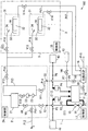
図1は本発明の第1の実施の形態に係る基板処理システムの構成を示す模式図である。
[1] First Embodiment (1) Overall Configuration of Substrate Processing System FIG. 1 is a schematic diagram showing a configuration of a substrate processing system according to a first embodiment of the present invention.
図1の基板処理システム100は、可搬式の洗浄ユニット1、複数の処理液供給ユニット2および基板処理装置3により構成される。基板処理装置3は、複数の処理ユニット31を含む。図1には、2つの処理ユニット31が図示される。各処理ユニット31では、基板Wに処理液を用いた処理が行われる。
A
洗浄ユニット1は、洗浄液タンク11、秤量タンク12,13、ポンプ14、フィルタ15、比抵抗計16および制御部17を含む。洗浄液タンク11の液入口と液出口との間に液循環用の配管P1が接続される。配管P1には、バルブV1、ポンプ14およびフィルタ15が介挿される。配管P1から分岐するように配管P2が設けられる。配管P2は処理液供給ユニット2の接続部C1に接続される。
The
秤量タンク12,13は、それぞれ配管P3,P4を通して洗浄液タンク11の液入口に接続される。配管P3,P4にはそれぞれバルブV2,V3が介挿される。秤量タンク12,13には、それぞれ配管P5,P6を通して薬液供給ユニット41,42が接続される。また、純水供給源43が配管P7を通して洗浄液タンク11の液入口に接続される。配管P7にはバルブV4が介挿される。
The weighing
薬液供給ユニット41から秤量タンク12に第1の薬液が供給され、薬液供給ユニット42から秤量タンク13に第2の薬液が供給される。この場合、バルブV2,V3が開くと、秤量タンク12,13の第1および第2の薬液が洗浄液タンク11に供給され、第1および第2の薬液が混合される。それにより、洗浄液が生成される。第1の薬液は、例えばアンモニアであり、第2の薬液は、例えば過酸化水素水である。この場合、アンモニアと過酸化水素水との混合液(以下、SC1と呼ぶ。)が洗浄液として生成される。第1の薬液が塩酸(HCl)であり、第2の薬液が過酸化水素水である場合には、塩酸と過酸化水素水との混合液(以下、SC2と呼ぶ)が洗浄液として生成される。
The first chemical solution is supplied from the chemical
バルブV4が開くと、純水供給源43から洗浄液タンク11に純水が供給される。その場合、純水が洗浄液として用いられる。純水の代わりに、純水以外のリンス液が洗浄液として用いられてもよい。この場合、リンス液としては、例えば炭酸水、オゾン水、磁気水、還元水(水素水)もしくはイオン水、またはIPA(イソプロピルアルコール)等の有機溶剤が用いられてもよい。
When the valve V4 is opened, pure water is supplied from the pure
洗浄液タンク11の液出口は配管P8を通して比抵抗計16に接続される。配管P8にはバルブV5が介挿される。比抵抗計16には配管P9が接続される。配管P9にはバルブV6が介挿される。配管P9は処理液供給ユニット2の接続部C2に接続される。また、比抵抗計16にはドレイン用の配管P10が接続される。制御部17は、バルブV1〜V6の開閉およびポンプ14の作動等の洗浄ユニット1の動作を制御する。
The liquid outlet of the cleaning
処理液供給ユニット2は、一または複数の処理液タンク21および制御部24を含む。本実施の形態では、1つの処理液タンク21が設けられる。処理液タンク21の液入口と接続部C1との間に配管P11が接続される。配管P11にはバルブV7,V8が介挿される。バルブV7,V8間で配管P11の部分には配管P12が接続される。配管P12にはバルブV9が介挿される。配管P12を通して窒素ガスが配管P11に供給可能となっている。
The processing
処理液タンク21の液入口と液出口との間に液循環用の配管P13が接続される。配管P13には、バルブV10、ポンプ22およびフィルタ23が介挿される。配管P13から分岐するように配管P14が設けられる。配管P14にはバルブV11が介挿される。配管P14は接続部C2に接続される。
A liquid circulation pipe P <b> 13 is connected between the liquid inlet and the liquid outlet of the
また、配管P13から分岐するように配管P15が設けられる。配管P15にはバルブV12が介挿される。配管P15から複数の配管P16が分岐している。 A pipe P15 is provided so as to branch from the pipe P13. A valve V12 is inserted in the pipe P15. A plurality of pipes P16 are branched from the pipe P15.
基板処理装置3における基板の処理時には、処理液供給ユニット2の処理液タンク21に、処理液が貯留される。処理液としては、薬液またはリンス液が用いられる。薬液としては、例えばバッファードフッ酸(BHF)、希フッ酸(DHF)、フッ酸(フッ化水素水:HF)、塩酸、硫酸、硝酸、リン酸、酢酸、シュウ酸もしくはアンモニア水等の水溶液、またはそれらの混合溶液等が用いられる。処理液がフォトレジスト液または現像液等であってもよい。
When processing the substrate in the
制御部24は、バルブV7〜V12の開閉およびポンプ22の作動等の処理液供給ユニット2の動作を制御する。基板処理装置3は、複数の処理ユニット31を含む。各処理ユニット31は、基板Wを保持する基板保持部32、カップ33およびノズル34を含む。ノズル34は配管P16に接続される。各配管P16にはバルブV13が介挿される。各処理ユニット31の排出口には配管P17が接続される。配管P17にはバルブV14が介挿される。配管P17は洗浄ユニット1の比抵抗計16に接続される。制御部35は、バルブV13,V14の開閉等の基板処理装置3の動作を制御する。
The
洗浄ユニット1は、接続部C1,C2で処理液供給ユニット2に対して接続および切り離し可能である。以下に説明する配管洗浄動作時には、洗浄ユニット1が処理液供給ユニット2に接続される。また、基板Wの処理時には、洗浄ユニット1が処理液供給ユニット2から切り離される。
The
(2)配管洗浄動作
次に、基板処理システム100における配管洗浄動作について説明する。洗浄ユニット1の制御部17、処理液供給ユニット2の制御部24および基板処理装置3の制御部35は、相互に通信を行いつつそれぞれ洗浄ユニット1、処理液供給ユニット2および基板処理装置3の動作を制御する。
(2) Pipe Cleaning Operation Next, a pipe cleaning operation in the
図2は図1の制御部17,24,35の制御による配管洗浄動作を示すフローチャートである。図3〜図11は図2の各ステップにおける基板処理システム100の配管洗浄動作を示す模式図である。
FIG. 2 is a flowchart showing a pipe cleaning operation under the control of the
ここでは、第1洗浄液、第2洗浄液および第3洗浄液を用いて処理液供給ユニット2および基板処理装置3の配管を洗浄する例について説明する。本例では、第1洗浄液はSC1であり、第2洗浄液は純水であり、第3洗浄液も純水である。なお、初期状態では、バルブV1〜V14が閉じているものとする。
Here, an example in which piping of the processing
まず、制御部17の制御により洗浄ユニット1が第1洗浄液の準備を行う(図2のステップS1)。この場合、制御部17は、図1のバルブV2,V3を開く。それにより、図3に太い点線の矢印で示すように、秤量タンク12から第1の薬液としてアンモニアが洗浄液タンク11に供給されかつ秤量タンク13から第2の薬液として過酸化水素水が洗浄液タンク11に供給され、アンモニアと過酸化水素水とが混合される。その結果、第1洗浄液としてSC1が生成される。その後、制御部17は、バルブV2,V3を閉じ、図1のバルブV1を開くとともにポンプ14を作動させる。それにより、図3に太い実線の矢印で示すように、第1洗浄液が配管P1を循環する。その結果、洗浄液タンク11内のパーティクルおよび第1洗浄液に含まれるパーティクルがフィルタ15により除去される。
First, the
次に、制御部24の制御により第1洗浄液を洗浄液タンク11から処理液タンク21に供給する(ステップS2)。この場合、制御部17が図1のバルブV1を閉じて洗浄液タンク11への第1洗浄液の帰還を停止した上で、制御部24は図1のバルブV7,V8を開く。それにより、図4に太い実線の矢印で示すように、配管P1から配管P11を通して処理液タンク21に第1洗浄液が供給される。
Next, the first cleaning liquid is supplied from the cleaning
その後、制御部24の制御により第1洗浄液の循環および洗浄準備を行う(ステップS3)。この場合、制御部24は、図1のバルブV7,V8を閉じ、バルブV10を開くとともに、ポンプ22を作動させる。それにより、図5に太い実線の矢印で示すように、第1洗浄液が配管P13を循環し、処理液タンク21内のパーティクルおよび第1洗浄液に含まれるパーティクルがフィルタ23により除去される。
Thereafter, circulation of the first cleaning liquid and preparation for cleaning are performed under the control of the control unit 24 (step S3). In this case, the
次に、制御部24および制御部35の制御により配管洗浄を行う(ステップS4)。この場合、制御部24は図1のバルブV12を開き、制御部35は図1のバルブV13,V14を開く。それにより、図6に太い実線の矢印で示すように、配管P13から配管P15,P16およびノズル34を通して第1洗浄液が各処理ユニット31内に供給される。各処理ユニット31内の第1洗浄液は、配管P17,P10を通して排出される。それにより、配管P13,P15〜P17、バルブV12〜V14およびノズル34が第1洗浄液により洗浄される。第1洗浄液による配管洗浄終了後に、制御部24はバルブV10,V12を閉じ、制御部35はバルブV13,V14を閉じる。
Next, pipe cleaning is performed under the control of the
ステップS3の第1洗浄液の循環および洗浄準備ならびにステップS4の配管洗浄と並行して、制御部17の制御により第2洗浄液の準備を行う(ステップS5)。この場合、制御部17は、図1のバルブV1,V4,V5を開く。それにより、図5および図6に太い一点鎖線の矢印で示すように、純水供給源43から配管P7を通して洗浄液タンク11に第2洗浄液として純水が供給されるとともに、図5および図6に白抜きの矢印で示すように、洗浄液タンク11内の第1洗浄液が配管P8,P10を通して排出される。また、第2洗浄液が配管P1を循環する。その結果、洗浄液タンク11、配管P1、ポンプ14およびフィルタ15内の第1洗浄液が第2洗浄液で置換される。また、制御部17は、比抵抗計16により第2洗浄液の比抵抗を測定する。比抵抗が所定値になると、制御部17は図1のバルブV5を閉じ、洗浄液タンク11に第2洗浄液を貯留する。その後、制御部17は図1のバルブV4を閉じる。
In parallel with the circulation and cleaning preparation of the first cleaning liquid in step S3 and the pipe cleaning in step S4, the second cleaning liquid is prepared under the control of the control unit 17 (step S5). In this case, the
次に、制御部24の制御により第2洗浄液を洗浄液タンク11から処理液タンク21に供給する(ステップS6)。この場合、制御部17が図1のバルブV1を閉じて洗浄液タンク11への第2洗浄液の帰還を停止した上で、制御部24は図1のバルブV7,V8を開く。それにより、図7に太い一点鎖線の矢印で示すように、配管P1から配管P11を通して処理液タンク21に第2洗浄液が供給される。また、制御部24は、バルブV10を開く。それにより、第2洗浄液が配管P13を循環し、洗浄液タンク11、配管P13、フィルタ15およびポンプ14の第1洗浄液が第2洗浄液で洗い流される。
Next, the second cleaning liquid is supplied from the cleaning
次に、制御部24および制御部35の制御により配管洗浄を行う(ステップS7)。この場合、制御部24は図1のバルブV12を開き、制御部35は図1のバルブV13,V14を開く。それにより、図8に太い一点鎖線の矢印で示すように、配管P13から配管P15,P16およびノズル34を通して第2洗浄液が各処理ユニット31内に供給される。各処理ユニット31内の第2洗浄液は、配管P17,P10を通して排出される。それにより、配管P13,P15〜P17、バルブV12〜V14およびノズル34が第2洗浄液により洗浄される。
Next, pipe cleaning is performed under the control of the
また、制御部17の制御により第2洗浄液の比抵抗が所定値であるか否かを判定する(ステップS8)。この場合、制御部17は、比抵抗計16により第2洗浄液の比抵抗を測定する。比抵抗が所定値でない場合には、ステップS6に戻り、洗浄液タンク11から処理液タンク21への第2洗浄液の供給および第2洗浄液による配管洗浄を行う。比抵抗が所定値になると、制御部24は図1のバルブV10,V12を閉じ、制御部35はバルブV13,V14を閉じる。
Moreover, it is determined whether the specific resistance of a 2nd washing | cleaning liquid is a predetermined value by control of the control part 17 (step S8). In this case, the
ステップS7の配管洗浄と並行して、制御部17の制御により第3洗浄液の準備を行う(ステップS9)。この場合、制御部17は、図1のバルブV1,V4,V5を開く。それにより、図8に太い二点鎖線の矢印で示すように、純水供給源43から配管P7を通して洗浄液タンク11に第3洗浄液として純水が供給されるとともに、図8に白抜きの矢印で示すように、洗浄液タンク11内の第2洗浄液が配管P8,P10を通して排出される。また、第3洗浄液が配管P1を循環する。その結果、洗浄液タンク11、配管P1、ポンプ14およびフィルタ15内の第2洗浄液が第3洗浄液で置換される。また、制御部17は、比抵抗計16により第3洗浄液の比抵抗を測定する。比抵抗が所定値になると、制御部17は図1のバルブV5を閉じ、洗浄液タンク11に第3洗浄液を貯留する。その後、制御部17はバルブV4を閉じる。
In parallel with the pipe cleaning in step S7, the third cleaning liquid is prepared under the control of the control unit 17 (step S9). In this case, the
次に、制御部24の制御により洗浄液タンク11から処理液タンク21への第3洗浄液の供給および処理液タンク21の洗浄を行う(ステップS10)。この場合、制御部17が図1のバルブV1を閉じて洗浄液タンク11への第3洗浄液の帰還を停止した上で、制御部24は図1のバルブV7,V8を開く。それにより、図9に太い二点鎖線の矢印で示すように、配管P1から配管P11を通して処理液タンク21に第3洗浄液が供給される。また、制御部24は、図1のバルブV10を開く。それにより、第3洗浄液が配管P13を循環し、洗浄液タンク11、配管P13、フィルタ15およびポンプ14の第2洗浄液が第3洗浄液で洗い流される。
Next, the third cleaning liquid is supplied from the cleaning
また、制御部17および制御部24の制御により第3洗浄液の比抵抗が所定値であるか否かを判定する(ステップS11)。この場合、制御部17は図1のバルブV6を開き、制御部24は図1のバルブV11を開く。それにより、図10に太い二点鎖線の矢印で示すように、処理液タンク21内および配管P13内の第3洗浄液が配管P14,P9,P10を通して排出される。制御部17は、比抵抗計16により第3洗浄液の比抵抗を測定する。比抵抗が所定値でない場合には、ステップS10に戻り、洗浄液タンク11から処理液タンク21への第3洗浄液の供給および第3洗浄液の循環を行う。
Further, it is determined whether or not the specific resistance of the third cleaning liquid is a predetermined value under the control of the
比抵抗が所定値になると、制御部24および制御部17の制御により処理液タンク21、配管P13,P14,P9,P10内の第3洗浄液を排出する(ステップS12)。処理液タンク21、配管P13,P14,P9,P10内の第3洗浄液の排出後、制御部24は図1のバルブV6,V10,V11を閉じる。
When the specific resistance reaches a predetermined value, the third cleaning liquid in the
上記のステップS9〜S12により処理液タンク21内を十分に洗浄することができる。
The inside of the
その後、制御部24の制御により窒素ガスの封入を行う(ステップS13)。この場合、制御部24がバルブV7,V9を開き、制御部17がバルブV1を開く。それにより、図11に太い破線の矢印で示すように、配管P11,P2,P1および洗浄液タンク11内に窒素ガスが封入される。
Thereafter, nitrogen gas is sealed under the control of the control unit 24 (step S13). In this case, the
(3)効果
本実施の形態に係る基板処理システム100においては、第1洗浄液による配管P13,P15〜P17の洗浄(ステップS4)と並行して、洗浄ユニット1において第2洗浄液の準備(ステップS5)を行うことができる。また、第2洗浄液による配管P13,P15〜P17の洗浄(ステップS7)と並行して、洗浄ユニット1において第3洗浄液の準備(ステップS9)を行うことができる。したがって、第1洗浄液および第2洗浄液による配管P13,P15〜P17の洗浄に要する時間を短縮することができる。その結果、複数の洗浄液を用いて短時間で配管P13,P15〜P17を洗浄することが可能になる。
(3) Effect In the
さらに、処理液供給ユニット2における第1洗浄液の循環および洗浄準備(ステップS3)と並行して、洗浄ユニット1において第3洗浄液の準備(ステップS9)を行うことも可能である。この場合、第1洗浄液および第2洗浄液による配管P13,P15〜P17の洗浄に要する時間をさらに短縮することができる。
Furthermore, in parallel with the circulation and cleaning preparation (step S3) of the first cleaning liquid in the processing
また、洗浄ユニット1から処理液タンク21への第1洗浄液の供給終了後に配管P11に介挿されたバルブV7,V8が閉じられるので、洗浄ユニット1から処理液タンク21への第1洗浄液の供給終了直後に洗浄ユニット1において第2洗浄液の準備を開始することができる。それにより、第1洗浄液および第2洗浄液による配管P13,P15〜P17の洗浄をより短時間で行うことが可能となる。
Further, since the valves V7 and V8 inserted in the pipe P11 are closed after the supply of the first cleaning liquid from the
また、配管P13,P15〜P17および処理液タンク21の洗浄後に、洗浄ユニット1の洗浄液タンク11内および配管P2,P11内に窒素ガスが封入されるので、パーティクル等の浸入による配管P2,P11および洗浄液タンク11内の汚染が防止される。
Further, after the pipes P13, P15 to P17 and the
さらに、洗浄ユニット1は、処理液供給ユニット2に対して接続および切り離し可能であるため、配管P13,P15〜P17の洗浄終了後に洗浄ユニット1を処理液供給ユニット2から切り離し、他の処理液供給ユニット2に接続することができる。それにより、単一の洗浄ユニット1により複数の処理液供給ユニット2および複数の基板処理装置3の配管を順次洗浄することができる。また、基板処理装置3による基板Wの処理時には、処理液供給ユニット2から洗浄ユニット1を切り離すことができるので、基板処理装置3の稼動時における基板処理システム100の大型化が抑制される。
Furthermore, since the
[2]第2の実施の形態
図12は本発明の第2の実施の形態に係る基板処理システムの構成を示す模式図である。第2の実施の形態に係る基板処理システム100の構成および動作は、以下の点を除いて第1の実施の形態に係る基板処理システム100の構成および動作と同様である。
[2] Second Embodiment FIG. 12 is a schematic diagram showing a configuration of a substrate processing system according to a second embodiment of the present invention. The configuration and operation of the
図12に示すように、本実施の形態では、処理液供給ユニット2に、図1の処理液タンク21に加えて処理液タンク21aが設けられる。バルブV7と接続部C1との間の配管P11の部分から分岐するように、配管P11aが設けられる。
As shown in FIG. 12, in the present embodiment, the processing
配管P11aは処理液タンク21aの液入口に接続される。配管P11aには、バルブV7a,V8aが介挿される。バルブV9の上流側の配管P12の部分から分岐するように、配管P12aが設けられる。バルブV7a,V8a間で配管P11aの部分に配管P12aが接続される。配管P12aにはバルブV9aが介挿される。配管P12aを通して窒素ガスが配管P11aに供給可能となっている。 The pipe P11a is connected to the liquid inlet of the processing liquid tank 21a. Valves V7a and V8a are inserted in the pipe P11a. A pipe P12a is provided so as to branch from a portion of the pipe P12 on the upstream side of the valve V9. A pipe P12a is connected to the pipe P11a between the valves V7a and V8a. A valve V9a is inserted in the pipe P12a. Nitrogen gas can be supplied to the pipe P11a through the pipe P12a.
処理液タンク21aの液入口と液出口との間に液循環用の配管P13aが接続される。配管P13aには、バルブV10a、ポンプ22aおよびフィルタ23aが介挿される。配管P13aから分岐するように配管P14aが設けられる。配管P14aにはバルブV11aが介挿される。配管P14aは接続部C2に接続される。また、配管P13aから分岐するように配管P15aが設けられる。配管P15aにはバルブV12aが介挿される。配管P15aから複数の配管P16aが分岐している。
A liquid circulation pipe P13a is connected between the liquid inlet and the liquid outlet of the processing liquid tank 21a. A valve V10a, a
制御部24は、バルブV7〜V12,V7a〜V12aの開閉およびポンプ22,22aの作動等の処理液供給ユニット2の動作を制御する。
The
基板処理装置3における基板の処理時には、処理液タンク21,21aに処理液が貯留される。処理液タンク21,21aに互いに異なる種類の処理液が貯留されてもよい。あるいは、処理液タンク21,21aに同じ成分を有しかつ互いに異なる濃度の処理液が貯留されてもよい。
When the substrate is processed in the
基板処理装置3の各処理ユニット31は、基板保持部32、カップ33およびノズル34に加えてノズル34aを含む。ノズル34aは配管P16aに接続される。各配管P16aにはバルブV13aが介挿される。制御部35は、バルブV13,V13a,V14の開閉等の基板処理装置3の動作を制御する。
Each
図12の基板処理システム100においては、バルブV7,V8,V7a,V8aが開かれると、洗浄ユニット1から2つの処理液タンク21,21aに洗浄液が同時に供給される。また、2つの処理液タンク21,21aに洗浄液が貯留された状態で、バルブV10,V10a,V12,V12aが開かれると、処理液タンク21,21a内の洗浄液が配管P15,P15a,P16,P16aおよびノズル34,34aを通して各処理ユニット31内に供給される。それにより、処理液供給ユニット2の2つの処理液タンク21,21aおよび配管P11〜P16,P11a〜P16aを同時に洗浄することができる。
In the
また、洗浄ユニット1から処理液供給ユニット2の処理液タンク21,21aにそれぞれ異なる洗浄液を供給することができる。この場合、バルブV7,V8を開くことにより、洗浄ユニット1から処理液タンク21に洗浄液を供給することができる。また、バルブV7a,V8aを開くことにより、洗浄ユニット1から処理液タンク21aに洗浄液を供給することができる。例えば、処理液タンク21に第1洗浄液としてSC1を供給した後、処理液タンク21に第2洗浄液として純水を供給する。その後、処理液タンク21aに第1洗浄液としてSC2を供給した後、処理液タンク21aに第2洗浄液として純水を供給する。
Also, different cleaning liquids can be supplied from the
この場合、SC1による配管洗浄と並行して洗浄ユニット1において純水を準備し、純水による配管洗浄と並行して洗浄ユニット1においてSC2を準備し、SC2による配管洗浄と並行して純水を準備することができる。それにより、SC1および純水による処理液タンク21および配管P13,P15〜P17の洗浄に要する時間を短縮することができるとともに、SC2および純水による処理液タンク21aおよび配管P13a,P15a〜P17aの洗浄に要する時間を短縮することができる。
In this case, pure water is prepared in the
[3]第3の実施の形態
第3の実施の形態に係る基板処理システムは、洗浄ユニット1の構成を除いて第1の実施の形態に係る基板処理システム100と同じ構成を有する。図13は本発明の第3の実施の形態における洗浄ユニットの主要部の構成を示す模式図である。
[3] Third Embodiment A substrate processing system according to a third embodiment has the same configuration as the
図13に示すように、本実施の形態における洗浄ユニット1は、洗浄液タンク11に加えて洗浄液タンク11aを含む。洗浄液タンク11aには、液循環用の配管P1aが接続される。配管P1aには、バルブV1a、ポンプ14aおよびフィルタ15aが介挿される。配管P1aから分岐するように配管P2aが設けられる。配管P2aは配管P2に接続される。
As shown in FIG. 13, the
図13では、図1の秤量タンク12,13、配管P5〜P10、バルブV4〜V6、比抵抗計16および制御部17の図示が省略されている。また、洗浄液タンク11aに接続される秤量タンク、バルブおよび配管の図示も省略されている。
In FIG. 13, the weighing
図13の洗浄ユニット1においては、洗浄液タンク11,11aに互いに異なる種類の洗浄液または互いに異なる濃度の洗浄液を貯留することができる。例えば、第1洗浄液としてSC1を用い、第2洗浄液として純水を用い、第3洗浄液としてSC2を用い、第4洗浄液として純水を用いる。この場合、第1洗浄液による配管洗浄と並行して洗浄液タンク11において第2洗浄液の準備を行うことができる。また、第3洗浄液による配管洗浄と並行して洗浄液タンク11aにおいて第4洗浄液の準備を行うことができる。したがって、複数の洗浄液を用いて短時間で配管を洗浄することが可能になる。
In the
[4]他の実施の形態
(a)上記の第1の実施の形態において、第1洗浄液としてSC1を用い、第2洗浄液として純水を用い、第3洗浄液としてSC2を用い、第4洗浄液として純水を用いてもよい。この場合には、第1洗浄液および第2洗浄液について図2のステップS1〜S8を行った後、第3洗浄液および第4洗浄液についてステップS1〜S8を行い、その後、ステップS9〜S13を行う。それにより、SC1を用いて処理液タンク21および配管P13,P15〜P17のパーティクルを洗浄し、SC2を用いて処理液タンク21および配管P13,P15〜P17の金属系汚染物を洗浄することができる。
[4] Other Embodiments (a) In the first embodiment described above, SC1 is used as the first cleaning liquid, pure water is used as the second cleaning liquid, SC2 is used as the third cleaning liquid, and the fourth cleaning liquid is used as the fourth cleaning liquid. Pure water may be used. In this case, after performing steps S1 to S8 in FIG. 2 for the first and second cleaning liquids, steps S1 to S8 are performed for the third and fourth cleaning liquids, and then steps S9 to S13 are performed. Thereby, particles in the
(b)図13の洗浄ユニット1において、配管P2と配管P2aとが接続されずにそれぞれ別個に設けられてもよい。また、図12の処理液供給ユニット2において、配管P11と配管P11aとが接続されずにそれぞれ別個に設けられてもよい。この場合、洗浄ユニット1の配管P2,P2aを処理液供給ユニット2の配管P11,P11aにそれぞれ接続することができる。この場合、図13の洗浄液タンク11から配管P2を通して図12の処理液タンク21に洗浄液が供給され、図13の洗浄液タンク11aから配管P2aを通して図12の処理液タンク21aに処理液が供給される。
(B) In the
(c)上記の実施の形態では、洗浄ユニット1、処理液供給ユニット2および基板処理装置3にそれぞれ制御部17,24,35が設けられるが、本発明はこれに限定されない。複数の制御部17,24,35に代わりに洗浄ユニット1、処理液供給ユニット2および基板処理装置3を制御する単一の制御部が設けられてもよい。
(C) In the above embodiment, the
[5]請求項の各構成要素と実施の形態の各部との対応関係
以下、請求項の各構成要素と実施の形態の各部との対応の例について説明するが、本発明は下記の例に限定されない。
[5] Correspondence relationship between each constituent element of claim and each part of the embodiment Hereinafter, an example of correspondence between each constituent element of the claim and each part of the embodiment will be described. It is not limited.
上記実施の形態においては、基板処理装置3が基板処理装置の例であり、処理液供給ユニット2,2aが処理液供給ユニットの例であり、洗浄ユニット1が処理ユニットの例であり、処理液タンク21,21aが処理液タンクの例であり、処理ユニット31が処理ユニットの例であり、配管P13,P15.P16,P13a,P15a,P16aが配管の例である。
In the above embodiment, the
また、配管P2,P11,P2aが供給経路の例であり、バルブV7,V8,V7a,V8aが開閉装置の例であり、窒素ガスが不活性ガスの例であり、配管P12が不活性ガス供給部の例であり、配管P13,P13aが循環経路の例である。 Pipes P2, P11, and P2a are examples of supply paths, valves V7, V8, V7a, and V8a are examples of switching devices, nitrogen gas is an example of inert gas, and pipe P12 is an inert gas supply. The pipes P13 and P13a are examples of circulation paths.
請求項の各構成要素として、請求項に記載されている構成または機能を有する他の種々の要素を用いることもできる。 As each constituent element in the claims, various other elements having configurations or functions described in the claims can be used.
本発明は、基板処理システムにおける配管の洗浄に利用することができる。 The present invention can be used for cleaning piping in a substrate processing system.
1 洗浄ユニット
2,2a 処理液供給ユニット
3 基板処理装置
11 洗浄液タンク
12,13 秤量タンク
14,22,14a,22a ポンプ
15,23,15a,23a フィルタ
16 比抵抗計
17,24,35 制御部
21 処理液タンク
31 処理ユニット
32 基板保持部
33 カップ
34,34a ノズル
41,42 薬液供給ユニット
43 純水供給源
100 基板処理システム
C1,C2 接続部
P1〜P17,P1a,P2a,P11a〜P17a 配管
V1〜V14,V1a,V7a〜V13a バルブ
W 基板
DESCRIPTION OF
Claims (7)
前記基板処理装置に配管を通して処理液を供給する処理液供給ユニットと、
洗浄ユニットとを備え、
前記処理液供給ユニットは、基板の処理時に、前記処理液を貯留する処理液タンクを含み、
前記基板処理装置は、基板の処理時に、基板に前記処理液を供給する処理ユニットを含み、
前記処理液タンクと前記処理ユニットとは前記配管により接続され、
前記洗浄ユニットは、前記配管の洗浄時に、第1洗浄液を前記処理液供給ユニットの前記処理液タンクに供給した後に、第2洗浄液の準備を行い、準備された前記第2洗浄液を前記処理液タンクに供給するように構成され、
前記処理液供給ユニットは、前記配管の洗浄時に、前記洗浄ユニットから供給された前記第1洗浄液を前記処理液タンクに貯留した後、前記処理液タンク内の前記第1洗浄液を前記配管を通して前記処理ユニットに供給することにより前記配管を洗浄し、前記洗浄ユニットから供給された前記第2洗浄液を前記処理液タンクに貯留した後、前記処理液タンク内の前記第2洗浄液を前記配管を通して前記処理ユニットに供給することにより前記配管を洗浄するように構成され、
前記洗浄ユニットは、前記第1洗浄液による前記配管の洗浄と並行して前記第2洗浄液の準備を行う、基板処理システム。 A substrate processing apparatus for processing the substrate;
A processing liquid supply unit for supplying a processing liquid to the substrate processing apparatus through a pipe;
A cleaning unit,
The processing liquid supply unit includes a processing liquid tank that stores the processing liquid when processing a substrate,
The substrate processing apparatus includes a processing unit that supplies the processing liquid to the substrate when processing the substrate,
The processing liquid tank and the processing unit are connected by the pipe,
The cleaning unit prepares a second cleaning liquid after supplying the first cleaning liquid to the processing liquid tank of the processing liquid supply unit when cleaning the pipe, and the prepared second cleaning liquid is used as the processing liquid tank. Configured to supply
The processing liquid supply unit stores the first cleaning liquid supplied from the cleaning unit in the processing liquid tank when cleaning the pipe, and then passes the first cleaning liquid in the processing liquid tank through the pipe. The pipe is cleaned by supplying to the unit, the second cleaning liquid supplied from the cleaning unit is stored in the processing liquid tank, and then the second cleaning liquid in the processing liquid tank is passed through the pipe to the processing unit. Configured to wash the piping by supplying to
The substrate processing system, wherein the cleaning unit prepares the second cleaning liquid in parallel with the cleaning of the pipe with the first cleaning liquid.
前記供給経路を開閉する開閉装置とをさらに備え、
前記開閉装置は、前記洗浄ユニットから前記処理液タンクへの前記第1洗浄液の供給時に前記供給経路を開き、前記処理液タンクへの前記第1洗浄液の供給後に前記供給経路を閉じる、請求項1記載の基板処理システム。 A supply path for supplying the first cleaning liquid and the second cleaning liquid from the cleaning unit to the processing liquid tank;
An opening / closing device for opening and closing the supply path;
The opening / closing device opens the supply path when the first cleaning liquid is supplied from the cleaning unit to the processing liquid tank, and closes the supply path after the first cleaning liquid is supplied to the processing liquid tank. The substrate processing system as described.
前記洗浄ユニットは、前記循環経路による前記第1洗浄液の循環と並行して前記第2洗浄液の準備を行う、請求項1〜3のいずれか一項に記載の基板処理システム。 The processing liquid supply unit further includes a circulation path for circulating the first cleaning liquid in the processing liquid tank through a filter,
The substrate processing system according to claim 1, wherein the cleaning unit prepares the second cleaning liquid in parallel with circulation of the first cleaning liquid through the circulation path.
前記洗浄ユニットは、前記複数の処理液タンクに接続可能に構成される、請求項1〜5のいずれかに記載の基板処理システム。 The processing liquid supply unit includes a plurality of the processing liquid tanks,
The substrate processing system according to claim 1, wherein the cleaning unit is configured to be connectable to the plurality of processing liquid tanks.
前記処理液供給ユニットは、基板の処理時に、前記処理液供給ユニットの処理液タンクから配管を通して前記基板処理装置の処理ユニットに処理液を供給するように構成され、
前記配管洗浄方法は、
前記配管の洗浄時に、洗浄ユニットから前記処理液供給ユニットの前記処理液タンクに第1洗浄液を供給するステップと、
前記処理液タンクへの前記第1洗浄液の供給後、前記処理液タンクから前記配管を通して前記基板処理装置の前記処理ユニットに前記第1洗浄液を供給することにより前記配管を洗浄するステップと、
前記第1洗浄液による前記配管の洗浄と並行して前記洗浄ユニットにおいて第2洗浄液の準備を行うステップと、
前記第1洗浄液による前記配管の洗浄後、前記洗浄ユニットから前記処理液タンクに前記第2洗浄液を供給するステップと、
前記処理液タンクへの前記第2洗浄液の供給後、前記処理液タンクから前記配管を通して前記処理ユニットに前記第2洗浄液を供給することにより前記配管を洗浄するステップとを含む、配管洗浄方法。 A piping cleaning method for cleaning piping in a substrate processing apparatus and a processing liquid supply unit,
The processing liquid supply unit is configured to supply a processing liquid to a processing unit of the substrate processing apparatus through a pipe from a processing liquid tank of the processing liquid supply unit when processing the substrate.
The pipe cleaning method is:
Supplying a first cleaning liquid from a cleaning unit to the processing liquid tank of the processing liquid supply unit when cleaning the piping;
After supplying the first cleaning liquid to the processing liquid tank, cleaning the pipe by supplying the first cleaning liquid from the processing liquid tank to the processing unit of the substrate processing apparatus through the pipe;
Preparing the second cleaning liquid in the cleaning unit in parallel with the cleaning of the pipe with the first cleaning liquid;
Supplying the second cleaning liquid from the cleaning unit to the processing liquid tank after cleaning the pipe with the first cleaning liquid;
Cleaning the pipe by supplying the second cleaning liquid from the processing liquid tank to the processing unit through the pipe after the second cleaning liquid is supplied to the processing liquid tank.
Priority Applications (11)
| Application Number | Priority Date | Filing Date | Title |
|---|---|---|---|
| JP2014065621A JP6186298B2 (en) | 2014-03-27 | 2014-03-27 | Substrate processing system and piping cleaning method |
| PCT/JP2015/001010 WO2015136872A1 (en) | 2014-03-10 | 2015-02-26 | Substrate processing system and tubing cleaning method |
| KR1020187007915A KR20180033594A (en) | 2014-03-10 | 2015-02-26 | Substrate processing system and tubing cleaning method |
| CN201811416745.0A CN109285800B (en) | 2014-03-10 | 2015-02-26 | Substrate processing system and pipe cleaning method |
| KR1020167028100A KR101842824B1 (en) | 2014-03-10 | 2015-02-26 | Substrate processing system and tubing cleaning method |
| US15/124,252 US20170014873A1 (en) | 2014-03-10 | 2015-02-26 | Substrate processing system and pipe cleaning method |
| KR1020187037875A KR102049193B1 (en) | 2014-03-10 | 2015-02-26 | Substrate processing system and tubing cleaning method |
| CN201580012432.7A CN106104762B (en) | 2014-03-10 | 2015-02-26 | Base plate processing system and pipeline cleaning method |
| TW104107388A TWI628007B (en) | 2014-03-10 | 2015-03-09 | Substrate processing system and method of cleaning pipe |
| TW109134990A TWI760883B (en) | 2014-03-10 | 2015-03-09 | Substrate processing apparatus |
| TW107118516A TWI709443B (en) | 2014-03-10 | 2015-03-09 | Substrate processing apparatus |
Applications Claiming Priority (1)
| Application Number | Priority Date | Filing Date | Title |
|---|---|---|---|
| JP2014065621A JP6186298B2 (en) | 2014-03-27 | 2014-03-27 | Substrate processing system and piping cleaning method |
Related Child Applications (1)
| Application Number | Title | Priority Date | Filing Date |
|---|---|---|---|
| JP2017148044A Division JP6347875B2 (en) | 2017-07-31 | 2017-07-31 | Substrate processing system and piping cleaning method |
Publications (3)
| Publication Number | Publication Date |
|---|---|
| JP2015191897A JP2015191897A (en) | 2015-11-02 |
| JP2015191897A5 JP2015191897A5 (en) | 2017-02-09 |
| JP6186298B2 true JP6186298B2 (en) | 2017-08-23 |
Family
ID=54426199
Family Applications (1)
| Application Number | Title | Priority Date | Filing Date |
|---|---|---|---|
| JP2014065621A Active JP6186298B2 (en) | 2014-03-10 | 2014-03-27 | Substrate processing system and piping cleaning method |
Country Status (1)
| Country | Link |
|---|---|
| JP (1) | JP6186298B2 (en) |
Families Citing this family (2)
| Publication number | Priority date | Publication date | Assignee | Title |
|---|---|---|---|---|
| JP6535649B2 (en) * | 2016-12-12 | 2019-06-26 | 株式会社荏原製作所 | Substrate processing apparatus, discharge method and program |
| JP6984431B2 (en) * | 2018-01-19 | 2021-12-22 | 東京エレクトロン株式会社 | Channel cleaning method and channel cleaning device |
Family Cites Families (2)
| Publication number | Priority date | Publication date | Assignee | Title |
|---|---|---|---|---|
| JP2004267965A (en) * | 2003-03-11 | 2004-09-30 | Dainippon Screen Mfg Co Ltd | Substrate processing apparatus and method for changeover of processing liquid |
| JP2012200712A (en) * | 2011-03-28 | 2012-10-22 | Kuraray Co Ltd | Piping washing method |
-
2014
- 2014-03-27 JP JP2014065621A patent/JP6186298B2/en active Active
Also Published As
| Publication number | Publication date |
|---|---|
| JP2015191897A (en) | 2015-11-02 |
Similar Documents
| Publication | Publication Date | Title |
|---|---|---|
| TWI709443B (en) | Substrate processing apparatus | |
| TWI690979B (en) | Substrate processing device and cleaning method of substrate processing device | |
| KR102378353B1 (en) | Substrate liquid processing method and substrate liquid processing apparatus | |
| JP2009543344A (en) | Post-etch wafer surface cleaning with liquid meniscus | |
| JP2011082276A (en) | Substrate processing apparatus, substrate processing method, and storage medium | |
| JP2020025013A (en) | Particle removal method for substrate processing apparatus and substrate processing apparatus | |
| JP6186298B2 (en) | Substrate processing system and piping cleaning method | |
| JP6347875B2 (en) | Substrate processing system and piping cleaning method | |
| JP2010056208A (en) | Substrate cleaning device | |
| TWI655974B (en) | Substrate processing method, liquid feeding method, and substrate processing apparatus | |
| JP2020004757A (en) | Substrate processing apparatus and substrate processing method | |
| KR102654039B1 (en) | Substrate processing apparatus, substrate processing method, and computer-readable recording medium | |
| JP2008311266A (en) | Manufacturing method of semiconductor device and substrate cleaning equipment | |
| JP2010050222A (en) | Substrate processing apparatus, substrate processing method, substrate processing program and computer-readable recording medium recording the substrate processing program | |
| JP2015191897A5 (en) | ||
| JP2010192566A (en) | Substrate processing apparatus and solvent reproducing method | |
| JP2005051099A (en) | Method of cleaning substrate | |
| JP5541627B2 (en) | Processing liquid supply apparatus and substrate processing apparatus provided with the same | |
| JPH09312276A (en) | Cleaning of substrate | |
| KR20090061399A (en) | Etching method for tft-lcd glass | |
| JP3648096B2 (en) | Processing equipment | |
| JPH0722366A (en) | Cleaning equipment for silicon wafer | |
| JP2003257924A (en) | Substrate treatment apparatus and piping component cleaning method therein | |
| KR101394088B1 (en) | Cleaning apparatus for substrate | |
| JPH10163156A (en) | Treatment method used in semiconductor-device production process and treatment apparatus by treatment liquid used in semiconductor-device production process |
Legal Events
| Date | Code | Title | Description |
|---|---|---|---|
| A521 | Request for written amendment filed |
Free format text: JAPANESE INTERMEDIATE CODE: A523 Effective date: 20161220 |
|
| A621 | Written request for application examination |
Free format text: JAPANESE INTERMEDIATE CODE: A621 Effective date: 20161220 |
|
| TRDD | Decision of grant or rejection written | ||
| A01 | Written decision to grant a patent or to grant a registration (utility model) |
Free format text: JAPANESE INTERMEDIATE CODE: A01 Effective date: 20170704 |
|
| A61 | First payment of annual fees (during grant procedure) |
Free format text: JAPANESE INTERMEDIATE CODE: A61 Effective date: 20170731 |
|
| R150 | Certificate of patent or registration of utility model |
Ref document number: 6186298 Country of ref document: JP Free format text: JAPANESE INTERMEDIATE CODE: R150 |
|
| R250 | Receipt of annual fees |
Free format text: JAPANESE INTERMEDIATE CODE: R250 |
|
| R250 | Receipt of annual fees |
Free format text: JAPANESE INTERMEDIATE CODE: R250 |
|
| R250 | Receipt of annual fees |
Free format text: JAPANESE INTERMEDIATE CODE: R250 |
|
| R250 | Receipt of annual fees |
Free format text: JAPANESE INTERMEDIATE CODE: R250 |