JP6184314B2 - Accumulator and air conditioner - Google Patents
Accumulator and air conditioner Download PDFInfo
- Publication number
- JP6184314B2 JP6184314B2 JP2013262662A JP2013262662A JP6184314B2 JP 6184314 B2 JP6184314 B2 JP 6184314B2 JP 2013262662 A JP2013262662 A JP 2013262662A JP 2013262662 A JP2013262662 A JP 2013262662A JP 6184314 B2 JP6184314 B2 JP 6184314B2
- Authority
- JP
- Japan
- Prior art keywords
- pressure refrigerant
- pipe
- low
- accumulator
- flow path
- Prior art date
- Legal status (The legal status is an assumption and is not a legal conclusion. Google has not performed a legal analysis and makes no representation as to the accuracy of the status listed.)
- Expired - Fee Related
Links
Images


Classifications
-
- F—MECHANICAL ENGINEERING; LIGHTING; HEATING; WEAPONS; BLASTING
- F25—REFRIGERATION OR COOLING; COMBINED HEATING AND REFRIGERATION SYSTEMS; HEAT PUMP SYSTEMS; MANUFACTURE OR STORAGE OF ICE; LIQUEFACTION SOLIDIFICATION OF GASES
- F25B—REFRIGERATION MACHINES, PLANTS OR SYSTEMS; COMBINED HEATING AND REFRIGERATION SYSTEMS; HEAT PUMP SYSTEMS
- F25B43/00—Arrangements for separating or purifying gases or liquids; Arrangements for vaporising the residuum of liquid refrigerant, e.g. by heat
- F25B43/006—Accumulators
-
- F—MECHANICAL ENGINEERING; LIGHTING; HEATING; WEAPONS; BLASTING
- F25—REFRIGERATION OR COOLING; COMBINED HEATING AND REFRIGERATION SYSTEMS; HEAT PUMP SYSTEMS; MANUFACTURE OR STORAGE OF ICE; LIQUEFACTION SOLIDIFICATION OF GASES
- F25B—REFRIGERATION MACHINES, PLANTS OR SYSTEMS; COMBINED HEATING AND REFRIGERATION SYSTEMS; HEAT PUMP SYSTEMS
- F25B13/00—Compression machines, plants or systems, with reversible cycle
-
- F—MECHANICAL ENGINEERING; LIGHTING; HEATING; WEAPONS; BLASTING
- F25—REFRIGERATION OR COOLING; COMBINED HEATING AND REFRIGERATION SYSTEMS; HEAT PUMP SYSTEMS; MANUFACTURE OR STORAGE OF ICE; LIQUEFACTION SOLIDIFICATION OF GASES
- F25B—REFRIGERATION MACHINES, PLANTS OR SYSTEMS; COMBINED HEATING AND REFRIGERATION SYSTEMS; HEAT PUMP SYSTEMS
- F25B2313/00—Compression machines, plants or systems with reversible cycle not otherwise provided for
- F25B2313/023—Compression machines, plants or systems with reversible cycle not otherwise provided for using multiple indoor units
- F25B2313/0233—Compression machines, plants or systems with reversible cycle not otherwise provided for using multiple indoor units in parallel arrangements
-
- F—MECHANICAL ENGINEERING; LIGHTING; HEATING; WEAPONS; BLASTING
- F25—REFRIGERATION OR COOLING; COMBINED HEATING AND REFRIGERATION SYSTEMS; HEAT PUMP SYSTEMS; MANUFACTURE OR STORAGE OF ICE; LIQUEFACTION SOLIDIFICATION OF GASES
- F25B—REFRIGERATION MACHINES, PLANTS OR SYSTEMS; COMBINED HEATING AND REFRIGERATION SYSTEMS; HEAT PUMP SYSTEMS
- F25B2313/00—Compression machines, plants or systems with reversible cycle not otherwise provided for
- F25B2313/027—Compression machines, plants or systems with reversible cycle not otherwise provided for characterised by the reversing means
- F25B2313/0272—Compression machines, plants or systems with reversible cycle not otherwise provided for characterised by the reversing means using bridge circuits of one-way valves
-
- F—MECHANICAL ENGINEERING; LIGHTING; HEATING; WEAPONS; BLASTING
- F25—REFRIGERATION OR COOLING; COMBINED HEATING AND REFRIGERATION SYSTEMS; HEAT PUMP SYSTEMS; MANUFACTURE OR STORAGE OF ICE; LIQUEFACTION SOLIDIFICATION OF GASES
- F25B—REFRIGERATION MACHINES, PLANTS OR SYSTEMS; COMBINED HEATING AND REFRIGERATION SYSTEMS; HEAT PUMP SYSTEMS
- F25B2400/00—General features or devices for refrigeration machines, plants or systems, combined heating and refrigeration systems or heat-pump systems, i.e. not limited to a particular subgroup of F25B
- F25B2400/05—Compression system with heat exchange between particular parts of the system
- F25B2400/051—Compression system with heat exchange between particular parts of the system between the accumulator and another part of the cycle
-
- F—MECHANICAL ENGINEERING; LIGHTING; HEATING; WEAPONS; BLASTING
- F25—REFRIGERATION OR COOLING; COMBINED HEATING AND REFRIGERATION SYSTEMS; HEAT PUMP SYSTEMS; MANUFACTURE OR STORAGE OF ICE; LIQUEFACTION SOLIDIFICATION OF GASES
- F25B—REFRIGERATION MACHINES, PLANTS OR SYSTEMS; COMBINED HEATING AND REFRIGERATION SYSTEMS; HEAT PUMP SYSTEMS
- F25B2400/00—General features or devices for refrigeration machines, plants or systems, combined heating and refrigeration systems or heat-pump systems, i.e. not limited to a particular subgroup of F25B
- F25B2400/05—Compression system with heat exchange between particular parts of the system
- F25B2400/054—Compression system with heat exchange between particular parts of the system between the suction tube of the compressor and another part of the cycle
Description
本発明は、アキュームレータと、空気調和装置とに関するものである。 The present invention also relates to a accumulator, to an air conditioner.
従来のアキュームレータとして、低圧冷媒を封入する容器と、容器内に低圧冷媒を流入させる低圧冷媒流入管と、容器内の低圧冷媒を容器外に流出させるU字管と、を備え、そのU字管が、外管によって隙間を有する状態で覆われるものがある。U字管と外管との間を高圧冷媒が通過して、容器内の低圧冷媒及びU字管の内側の低圧冷媒と、その高圧冷媒と、が熱交換する。その熱交換によって、容器内の低圧冷媒及びU字管の内側の低圧冷媒が気化及び過熱され、また、U字管と外管との間を通過する高圧冷媒が過冷却される(例えば、特許文献1を参照。)。
As a conventional accumulator, a U-tube is provided that includes a container that encloses a low-pressure refrigerant, a low-pressure refrigerant inflow pipe that allows the low-pressure refrigerant to flow into the container, and a U-shaped pipe that allows the low-pressure refrigerant in the container to flow out of the container. However, there are some which are covered with a gap by the outer tube. The high-pressure refrigerant passes between the U-tube and the outer tube, and heat exchange is performed between the low-pressure refrigerant in the container and the low-pressure refrigerant inside the U-tube and the high-pressure refrigerant. By the heat exchange, the low-pressure refrigerant in the container and the low-pressure refrigerant inside the U-shaped tube are vaporized and superheated, and the high-pressure refrigerant passing between the U-shaped tube and the outer tube is supercooled (for example, patent See
従来のアキュームレータでは、内側に直管が挿入された外管を直管と共に曲げて、U字管の折返部を形成するため、その折返部において、U字管と外管との間の隙間を確保することが困難であり、製造性が低いという問題点があった。また、従来のアキュームレータを、冷媒循環回路が複雑化される傾向にある、流路切替機構の切替動作によって暖房運転と冷房運転とが切り替えられる空気調和装置に、どう適用するかが、具現化されていないという問題点があった。 In the conventional accumulator, the outer tube with the straight pipe inserted inside is bent together with the straight pipe to form a folded portion of the U-shaped tube. Therefore, in the folded portion, a gap between the U-shaped tube and the outer tube is formed. There is a problem that it is difficult to ensure and the manufacturability is low. Further, it is embodied how the conventional accumulator is applied to an air conditioner in which the heating operation and the cooling operation are switched by the switching operation of the flow path switching mechanism, which tends to complicate the refrigerant circulation circuit. There was a problem that not.
本発明は、上記のような課題を背景としてなされたものであり、製造性が向上されたアキュームレータを得るものである。また、本発明は、そのようなアキュームレータを備えた空気調和装置を得るものである。また、本発明は、アキュームレータの適用が具現化された空気調和装置を得るものである。 The present invention has been made against the background of the above problems, and provides an accumulator with improved manufacturability. The present invention also provides an air conditioner equipped with such an accumulator. The present invention also provides an air conditioner in which the application of the accumulator is embodied .
本発明に係るアキュームレータは、低圧冷媒を封入する容器と、前記容器内に前記低圧冷媒を流入させる低圧冷媒流入管と、前記容器内に、上流側管状部、前記上流側管状部の下方側の端部に連通する低圧冷媒折返部、及び、前記低圧冷媒折返部に下方側の端部が連通する下流側管状部、を有し、前記容器内の前記低圧冷媒を、前記上流側管状部の上方側の端部から前記下流側管状部の上方側の端部まで通過させて、前記容器外に流出させる低圧冷媒流出体と、を備え、前記上流側管状部の少なくとも一部は、第1外管によって隙間を有する状態で覆われ、前記下流側管状部の少なくとも一部は、第2外管によって隙間を有する状態で覆われ、前記第1外管と前記第2外管とは、橋渡し管によって連通され、前記上流側管状部と前記第1外管との間の前記隙間、前記橋渡し管、及び、前記下流側管状部と前記第2外管との間の前記隙間、を高圧冷媒が通過し、前記橋渡し管の少なくとも一部の流路断面積は、前記上流側管状部と前記第1外管との間の前記隙間の流路断面積、及び、前記下流側管状部と前記第2外管との間の前記隙間の流路断面積と比較して、小さいものである。 An accumulator according to the present invention includes a container that encloses a low-pressure refrigerant, a low-pressure refrigerant inflow pipe that allows the low-pressure refrigerant to flow into the container, an upstream tubular portion in the container, and a lower side of the upstream tubular portion. A low-pressure refrigerant folding portion communicating with the end portion, and a downstream tubular portion communicating with the low-pressure refrigerant folding portion at a lower end thereof, and the low-pressure refrigerant in the container is supplied to the upstream tubular portion. A low-pressure refrigerant outflow body that passes from the upper end portion to the upper end portion of the downstream tubular portion and flows out of the container, wherein at least a part of the upstream tubular portion is a first portion. The outer pipe is covered with a gap, and at least a part of the downstream tubular portion is covered with a gap with the second outer pipe, and the first outer pipe and the second outer pipe are bridged. Communicated by a tube, the upstream tubular portion and the first outer tube The gap between the bridging tube and the gap between the downstream tubular portion and the second outer tube, the passing high-pressure refrigerant, at least a portion of the flow path cross-sectional area of the bridging tube Compared with the cross-sectional area of the gap between the upstream tubular portion and the first outer pipe and the cross-sectional area of the gap between the downstream tubular portion and the second outer pipe And it is small .
本発明に係るアキュームレータは、第1外管と第2外管とが、橋渡し管によって連通されるため、低圧冷媒折返部が外管によって覆われなくてもよくなり、隙間の確保を配慮しつつ、低圧冷媒流出体の折返部を成形しなくてもよくなって、低圧冷媒流出体の製造性が向上される。 In the accumulator according to the present invention, since the first outer pipe and the second outer pipe are communicated with each other by a bridge pipe, the low-pressure refrigerant return portion does not have to be covered by the outer pipe, and consideration is given to securing a gap. Thus, the folded portion of the low-pressure refrigerant effluent does not need to be formed, and the productivity of the low-pressure refrigerant effluent is improved.
以下、本発明に係るアキュームレータについて、図面を用いて説明する。
なお、以下で説明する構成、作用、製造工程等は、一例であり、本発明に係るアキュームレータは、そのような構成、作用、製造工程等である場合に限定されない。また、細かい構造については、適宜図示を簡略化又は省略している。また、重複する説明については、適宜簡略化又は省略している。
Hereinafter, an accumulator according to the present invention will be described with reference to the drawings.
The configuration, operation, manufacturing process, and the like described below are examples, and the accumulator according to the present invention is not limited to such a configuration, operation, manufacturing process, and the like. Further, the illustration of the fine structure is simplified or omitted as appropriate. In addition, overlapping descriptions are simplified or omitted as appropriate.
実施の形態1.
以下に、実施の形態1に係るアキュームレータを説明する。
<アキュームレータの構成及び作用>
以下に、実施の形態1に係るアキュームレータの構成及び作用について説明する。
図1〜図3は、実施の形態1に係るアキュームレータの、構成及び作用を説明するための図である。
The accumulator according to the first embodiment will be described below.
<Configuration and operation of accumulator>
The configuration and operation of the accumulator according to
1-3 is a figure for demonstrating a structure and effect | action of the accumulator which concerns on
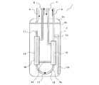
図1に示されるように、アキュームレータ1は、容器2と、低圧冷媒流入管3と、低圧冷媒流出体4と、高圧冷媒流入管5と、高圧冷媒流出管6と、を有する。容器2は、低圧冷媒を封入する。低圧冷媒流入管3は、容器2内に低圧冷媒を流入させる。低圧冷媒流出体4は、容器2内から低圧冷媒を流出させる。高圧冷媒流入管5は、容器2内に高圧冷媒を流入させる。高圧冷媒流出管6は、容器2内から高圧冷媒を流出させる。
As shown in FIG. 1, the
容器2は、キャップ2aと、シェル2bと、で構成されるとよく、低圧冷媒流入管3と低圧冷媒流出体4と高圧冷媒流入管5と高圧冷媒流出管6とは、キャップ2aの上面に形成された貫通穴を貫通する状態で、固定される。そのように構成されることで、低圧冷媒流入管3と低圧冷媒流出体4と高圧冷媒流入管5と高圧冷媒流出管6とを、容器2が開いた状態で、容器2内に取り付けることができ、また、その後、キャップ2aの接合という簡易な作業で、容器2を封止することができるため、アキュームレータ1の製造性が向上される。
The
低圧冷媒流出体4は、容器2内の上方から下方に延びる第1管11と、第1管11の下方側の端部に接続されたU字管12と、U字管12に下方側の端部が接続された第2管13と、を有する。図2に示されるように、第1管11とU字管12と第2管13とは、別部材である。容器2内に流入する低圧冷媒は、第1管11の上方側の端部から低圧冷媒流出体4に流入し、第1管11、U字管12、第2管13の順に通過して、容器2外に流出する。以下では、低圧冷媒流出体4の低圧冷媒が通過する流路を、低圧冷媒流路4aと記載する。U字管12は、U字状でなくてもよく、また、U字状の流路が形成されたブロック等であってもよい。第1管11は、本発明における「上流側管状部」に相当する。U字管12は、本発明における「低圧冷媒折返部」に相当する。第2管13のうちの容器2内にある領域は、本発明における「下流側管状部」に相当する。
The low-pressure
なお、低圧冷媒流出体4の第1管11とU字管12と第2管13とが、1つの部材、つまり、1つのU字管であってもよい。そのような場合には、その1つのU字管の、第1管11に相当する部分は、本発明における「上流側管状部」に相当する。その1つのU字管の、U字管12に相当する部分は、本発明における「低圧冷媒折返部」に相当する。その1つのU字管の、第2管13のうちの容器2内にある領域に相当する部分は、本発明における「下流側管状部」に相当する。
In addition, the 1st pipe |
低圧冷媒流出体4の第1管11とU字管12と第2管13とが、別部材であることで、第1管11とU字管12と第2管13とが、1つのU字管である場合と比較して、容量の異なる複数のアキュームレータ1に共通で使用できる部材(U字管12等)を増加させることができ、製造コストが削減される。また、第1管11とU字管12と第2管13とが、1つのU字管である場合には、折返部のスプリング効果によって、その1つのU字管の両端部が少なからず開いてしまうが、第1管11とU字管12と第2管13とが、別部材である場合には、U字管12が別部材であることで、その開きを低減すること、又は、無くすことが容易であるため、第1管11の上方側の端部と第2管13の上方側の端部とが開いてしまうことが抑制され、その結果、容器2内の低圧冷媒の密封性が向上され、また、アキュームレータ1の製造時の作業性が向上される。
The
第1管11の少なくとも一部は、第1外管14によって隙間を有する状態で覆われる。第1外管14に、高圧冷媒流出管6が接続される。第2管13の少なくとも一部は、第2外管15によって隙間を有する状態で覆われる。第2外管15に、高圧冷媒流入管5が接続される。第1外管14と第2外管15とは、橋渡し管16によって連通される。高圧冷媒流入管5から、第2管13と第2外管15との間の隙間に流入した高圧冷媒は、橋渡し管16、第1管11と第1外管14との間の隙間、高圧冷媒流出管6を順に通過して、容器2外に流出する。以下では、低圧冷媒流出体4の高圧冷媒が通過する流路を、高圧冷媒流路4bと記載する。
At least a part of the
第1外管14と第2外管15とが、橋渡し管16によって連通されるため、U字管12が外管によって覆われなくてもよくなるため、U字管12と外管との間の隙間の確保を配慮しつつ、U字管12、つまり、低圧冷媒流出体4の折返部を成形しなくてもよくなり、低圧冷媒流出体4の製造性が向上される。
Since the first
また、容器2内及び低圧冷媒流路4aを通過する低圧冷媒と、高圧冷媒流路4bを通過する高圧冷媒と、が熱交換することで、容器2内及び低圧冷媒流路4aを通過する低圧冷媒の気化及び過熱が促進されて、低圧冷媒流出体4から、液冷媒を殆ど含まない充分に過熱されたガス冷媒が流出することとなり、また、高圧冷媒流路4bを通過する高圧冷媒の過冷却が促進されて、高圧冷媒流出管6から充分に過冷却された液冷媒が流出することとなる。
In addition, the low pressure refrigerant passing through the
また、低圧冷媒流路4aを通過する低圧冷媒と高圧冷媒流路4bを通過する高圧冷媒とが、対向流になることで、並向流である場合と比較して、低圧冷媒流路4aのうちの下流側の領域を通過する低圧冷媒の、高圧冷媒に対する温度差が大きくなり、且つ、高圧冷媒流路4bのうちの下流側の領域を通過する高圧冷媒の、低圧冷媒に対する温度差が大きくなるため、低圧冷媒流出体4における熱交換効率が向上されて、容器2内及び低圧冷媒流路4aを通過する低圧冷媒の気化及び過熱と、高圧冷媒流路4bを通過する高圧冷媒の過冷却と、が更に促進される。
In addition, the low-pressure refrigerant passing through the low-pressure
また、低圧冷媒流出体4の第1管11とU字管12と第2管13とが、別部材であることで、第1管11及び第2管13が外管によって覆われないタイプの低圧冷媒流出体と、共通で使用できる部材(U字管12等)を増加させることができ、製造コストが削減される。
Moreover, the 1st pipe |
第1外管14の長さが、第2外管15の長さと比較して長いとよい。そのように構成されることで、第1管11の周辺の低圧冷媒の気化が更に促進されるため、第1管11の上方側の端部から液冷媒が流入することの抑制を更に確実化することと、高圧冷媒流路4bが必要以上に長くなって、高圧冷媒流路4bを通過する高圧冷媒に生じる圧力損失が大きくなることの抑制と、を両立することが可能となる。
The length of the first
U字管12には、油戻し穴17が形成される。油戻し穴17は、容器2内の下方、特に、橋渡し管16と比較して下側に位置する。油戻し穴17を介して、容器2の底部に滞留する油、例えば圧縮機の潤滑油等が、低圧冷媒流路4aに流入し、低圧冷媒と共にアキュームレータ1から流出する。油戻し穴17が、外管によって覆われていないU字管12に形成されるため、低圧冷媒流出体4の製造性が向上される。油戻し穴17は、本発明における「油流入流路」に相当する。
An
第2管13のうちの下流側の領域が、第2外管15によって覆わず、その領域にストロー管18の一方の端部が接続される。ストロー管18の他方の端部(先端部)は、容器2内の下方、特に、橋渡し管16と比較して下側に位置する。ストロー管18は、容器2の底部に滞留する油、例えば圧縮機の潤滑油等を吸入して、低圧冷媒流路4aに流入させる。ストロー管18が、外管によって覆われていない第2管13のうちの下流側の領域に接続されるため、低圧冷媒流出体4の製造性が向上される。また、ストロー管18が、低圧冷媒流路4aの出口に近い領域に接続されるため、ストロー管18の両端部の間のヘッド差が拡大されて、容器2の底部に滞留する油、例えば圧縮機の潤滑油等の吸入が促進される。ストロー管18は、本発明における「油流入流路」に相当する。
The downstream area of the
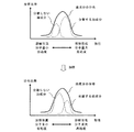
橋渡し管16が、油戻し穴17及びストロー管18の先端部と比較して上側に位置することで、容器2内における、油、例えば圧縮機の潤滑油等と、液冷媒と、の分離が促進される。つまり、図3に示されるように、容器2内に流入する油、例えば圧縮機の潤滑油等には、溶解性の異なる油成分が混在する傾向にあり、溶解性の低い油成分は液冷媒から分離されるが、溶解性の高い油成分は液冷媒に溶け込んで分離されない。そして、橋渡し管16が、油戻し穴17及びストロー管18の先端部と比較して下側に位置する場合には、橋渡し管16によって、容器2の底部に滞留する油、例えば圧縮機の潤滑油等と、液冷媒と、が加熱されて、分離されない油成分が増加する。それに対し、橋渡し管16が、油戻し穴17及びストロー管18の先端部と比較して上側に位置する場合には、橋渡し管16によって、容器2の底部に滞留する油、例えば圧縮機の潤滑油等と、液冷媒と、が加熱されることが抑制されて、分離されない油成分が増加することが抑制され、容器2内における、油、例えば圧縮機の潤滑油等と、液冷媒と、の二層化が促進されることとなる。その結果、アキュームレータ1の油、例えば圧縮機の潤滑油等の返油性能が向上されて、圧縮機等の故障等を抑制することの確実性が更に向上される。
Since the
なお、低圧冷媒流出体4が、油戻し穴17とストロー管18とのいずれか一方のみを有していてもよい。特に、圧縮機等の運転状態によって、低圧冷媒流路4aを通過する低圧冷媒の流量が大きく変動する場合には、低圧冷媒流出体4が、油戻し穴17とストロー管18とを有するとよい。
Note that the low-pressure
図2に示されるように、U字管12には、支持部材21が固定される。図示しない高圧冷媒流入管5と図示しない高圧冷媒流出管6と第1管11と第2管13とに、支持部材22が固定される。支持部材21、22の外周面21a、22aは、シェル2bの内周面に沿う形状であり、シェル2bの内周面に接合される。
As shown in FIG. 2, a
<アキュームレータの製造方法>
以下に、実施の形態1に係るアキュームレータの製造方法について説明する。
図4は、実施の形態1に係るアキュームレータの、製造方法を説明するための図である。
<Accumulator manufacturing method>
Below, the manufacturing method of the accumulator which concerns on
FIG. 4 is a diagram for explaining a manufacturing method of the accumulator according to the first embodiment.
図4に示されるように、S101において、第1管11の少なくとも一部が、第1外管14によって隙間を有する状態で覆われ、且つ、第2管13の少なくとも一部が、第2外管15によって隙間を有する状態で覆われ、且つ、第1外管14と第2外管15とが橋渡し管16によって連通され、且つ、第1管11及び第2管13とU字管12とが連通された状態になるように、各部材が位置決めされ、S102において、U字管12以外がろう付け等によって接合される。なお、S102の後に、U字管12が位置決めされてもよい。U字管12は、本発明における「中継部材」に相当する。
As shown in FIG. 4, in S101, at least a part of the
S103において、高圧冷媒流入管5が、第2外管15にろう付け等によって接合され、高圧冷媒流出管6が、第1外管14にろう付け等によって接合された後、S104において、高圧冷媒流路4bの気密試験が行われる。そのような工程であることで、低圧冷媒流路4aと比較して、高圧な冷媒が通過する高圧冷媒流路4bの気密性の確保が、確実化される。
In S103, the high-pressure
S105において、U字管12とストロー管18とが、ろう付け等によって接合されて、低圧冷媒流出体4が形成された後、S106において、低圧冷媒流出体4に支持部材21、22が固定される。図2に示されるように、U字管12が、支持部材21に形成された貫通穴に挿入された状態で、その貫通穴をカシメ加工することによって、支持部材21がU字管12に固定される場合には、U字管12が位置決めされる以前に、支持部材21が固定されるとよい。そのような工程であることで、第1外管14及び第2外管15の外径が、その貫通穴の内径と比較して太い場合に、第1外管14及び第2外管15によって、支持部材21をU字管12に取り付けられなくなることが回避される。低圧冷媒流出体4は、本発明における「冷媒流出体」に相当する。
In S105, the
S107において、シェル2bの内周面と支持部材21、22の外周面21a、22aとが、溶接等によって接合された後、S108において、事前に低圧冷媒流入管3が接合されたキャップ2aが位置決めされ、S109において、シェル2bにキャップ2aが接合されて、容器2が封止される。
In S107, after the inner peripheral surface of the
<アキュームレータの使用例>
実施の形態1に係るアキュームレータの使用例について説明する。
なお、以下の使用例におけるアキュームレータ1は、第1外管14と第2外管15とを、橋渡し管16によって連通させるものでなくてもよく、低圧冷媒流路4aの少なくとも一部が、外管によって覆われていればよい。つまり、例えば、アキュームレータ1が、U字管12を、隙間を有する状態で覆う外管を有し、第1外管14と第2外管15とを、その外管によって連通させたものであってもよい。
<Usage example of accumulator>
A usage example of the accumulator according to the first embodiment will be described.
In addition, the
(使用例−1)
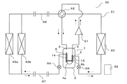
図5及び図6は、実施の形態1に係るアキュームレータの、使用例−1を説明するための図である。なお、図5及び図6では、暖房運転時の冷媒の流れが実線の矢印で示され、冷房運転時の冷媒の流れが点線の矢印で示される。また、暖房運転時の四方弁62の流路が実線で示され、冷房運転時の四方弁62の流路が点線で示される。
図5に示されるように、アキュームレータ1は、空気調和装置50に適用される。
(Usage example-1)
5 and 6 are diagrams for explaining a usage example-1 of the accumulator according to the first embodiment. In FIGS. 5 and 6, the refrigerant flow during the heating operation is indicated by solid arrows, and the refrigerant flow during the cooling operation is indicated by dotted arrows. Further, the flow path of the four-
As shown in FIG. 5, the
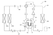
空気調和装置50は、アキュームレータ1、圧縮機61、四方弁62、室内熱交換器63a、63b、膨張装置64、及び、室外熱交換器65が、延長配管66、67を含む配管で接続された冷媒循環回路51と、冷媒循環回路51の動作を司る制御装置52と、を有する。室内熱交換器63a、63bは、1つのみ設けられてもよい。四方弁62は、圧縮機61から吐出された冷媒の循環方向を切り替え得る他の機構であってもよい。四方弁62は、本発明における「第1流路切替機構」に相当する。膨張装置64は、本発明における「第1膨張装置」に相当する。
In the
アキュームレータ1の低圧冷媒流路4aを通過した冷媒は、圧縮機61に吸入される。第1外管14に接続された高圧冷媒流出管6が、膨張装置64に連通され、且つ、第2外管15に接続された高圧冷媒流入管5が、室内熱交換器63a、63bに連通されるように、アキュームレータ1の高圧冷媒流路4bが接続される。
The refrigerant that has passed through the low-pressure
暖房運転では、制御装置52によって、四方弁62の流路が、図5に示される実線のように、切り替えられる。圧縮機61で高圧になったガス冷媒は、四方弁62を通って、室内熱交換器63a、63bに流入し、ファン等によって供給される室内空気との熱交換によって凝縮され、過冷却された液冷媒になる。過冷却された液冷媒は、アキュームレータ1の高圧冷媒流路4bに流入して、アキュームレータ1の低圧冷媒流路4aを通過する低圧冷媒、及び、容器2内の低圧冷媒と熱交換して、更に過冷却された液冷媒になる。更に過冷却された液冷媒は、膨張装置64に流入し、膨張装置64で膨張されて、低圧の気液二相冷媒になる。低圧の気液二相冷媒は、室外熱交換器65に流入して、ファン等によって供給される外気等との熱交換によって蒸発される。室外熱交換器65を通過した冷媒は、四方弁62を通って、アキュームレータ1の容器2内に流入する。アキュームレータ1の容器2内に流入した冷媒は、容器2内、及び、低圧冷媒流路4aを通過する際に、アキュームレータ1の高圧冷媒流路4bを通過する高圧冷媒との熱交換によって、過熱され又は乾き度が高められ、液冷媒を殆ど含まない充分に過熱されたガス冷媒になって、再度、圧縮機61に吸入される。
In the heating operation, the flow path of the four-
冷房運転では、制御装置52によって、四方弁62の流路が、図5に示される点線のように、切り替えられる。圧縮機61で高圧になったガス冷媒は、四方弁62を通って、室外熱交換器65に流入し、ファン等によって供給される外気等との熱交換によって凝縮され、過冷却された液冷媒になる。過冷却された液冷媒は、膨張装置64に流入し、膨張装置64で膨張されて、低圧の気液二相冷媒になる。低圧の気液二相冷媒は、アキュームレータ1の高圧冷媒流路4bに流入して、延長配管66、室内熱交換器63a、63b、延長配管67等で生じる圧力損失分だけ更に減圧された、アキュームレータ1の低圧冷媒流路4aを通過する低圧冷媒、及び、容器2内の低圧冷媒と熱交換した後、室内熱交換器63a、63bに流入して、ファン等によって供給される室内空気との熱交換によって蒸発される。室内熱交換器63a、63bを通過した冷媒は、四方弁62を通って、アキュームレータ1の容器2内に流入する。アキュームレータ1の容器2内に流入した冷媒は、容器2内、及び、低圧冷媒流路4aを通過する際に、アキュームレータ1の高圧冷媒流路4bを通過する高圧冷媒との熱交換によって、過熱され又は乾き度が高められ、液冷媒を殆ど含まない充分に過熱されたガス冷媒になって、再度、圧縮機61に吸入される。
In the cooling operation, the flow path of the four-
つまり、冷媒循環回路51が暖房運転を行う際においては、容器2内及び低圧冷媒流路4aを、圧縮機61に吸入される前の低圧冷媒が通過し、高圧冷媒が、高圧冷媒流路4bを通過した後に、膨張装置64に流入する。その結果、容器2内及び低圧冷媒流路4aを通過する低圧冷媒の気化及び過熱を、大きな圧力差を生じさせる膨張装置64で膨張される前の高圧冷媒の利用によって確実化できるため、低圧冷媒流出体4から液冷媒を殆ど含まない充分に過熱されたガス冷媒が流出することが確実化されて、冷媒循環回路51が四方弁62の切替動作によって暖房運転と冷房運転とを切り替えるものであるにも関わらず、圧縮機61の故障、運転効率の低下等を抑制することができる。また、高圧冷媒流路4bを通過する高圧冷媒の過冷却を、大きな圧力差を生じさせる圧縮機61で加圧される前の低圧冷媒の利用によって確実化できるため、冷媒循環回路51が四方弁62の切替動作によって暖房運転と冷房運転とを切り替えるものであるにも関わらず、室外熱交換器65の入口側における冷媒の乾き度を小さくして、室外熱交換器65で生じる圧力損失を低減することができる。また、室外熱交換器65における冷媒の分配性能を向上して、室外熱交換器65の熱交換効率を向上することができる。
That is, when the
また、冷媒循環回路51が暖房運転を行う際においては、更に、低圧冷媒流路4aを通過する低圧冷媒と高圧冷媒流路4bを通過する高圧冷媒とが、対向流となる。その結果、並向流である場合と比較して、低圧冷媒流路4aを通過する低圧冷媒の気化及び過熱と、高圧冷媒流路4bを通過する高圧冷媒の過冷却と、を、更に確実化できるため、冷媒循環回路51が四方弁62の切替動作によって暖房運転と冷房運転とを切り替えるものであるにも関わらず、圧縮機61の故障、運転効率の低下等を更に抑制することができ、また、室外熱交換器65で生じる圧力損失の低減と室外熱交換器65の熱交換効率の向上とを、更に促進することができる。
Further, when the
また、特に、冷媒循環回路51が暖房運転を行う際に、高圧冷媒流路4bを通過した高圧冷媒が、膨張装置64に流入し、また、低圧冷媒流路4aを通過する低圧冷媒と高圧冷媒流路4bを通過する高圧冷媒とが、対向流となる。暖房運転時は、冷房運転時と比較して、蒸発器で冷媒と熱交換する空気の温度が低くなる傾向にあるため、冷媒の過熱が困難になる傾向にある。そのため、暖房運転時の低圧冷媒流出体4における熱交換効率が優先して向上されることで、圧縮機61の故障、運転効率の低下等を抑制し、且つ、室外熱交換器65で生じる圧力損失の低減と室外熱交換器65の熱交換効率の向上とを促進することを、低コストに実現することができる。
In particular, when the
なお、図6に示されるように、冷媒循環回路51が冷房運転を行う際において、高圧冷媒が、高圧冷媒流路4bを通過した後に、膨張装置64に流入し、また、低圧冷媒流路4aを通過する低圧冷媒と高圧冷媒流路4bを通過する高圧冷媒とが、対向流となってもよい。そのような場合でも、特に、冷媒循環回路51が冷房運転を行う際に、低圧冷媒流路4aを通過する低圧冷媒の気化及び過熱と、高圧冷媒流路4bを通過する高圧冷媒の過冷却と、を確実化できるため、冷媒循環回路51が四方弁62の切替動作によって暖房運転と冷房運転とを切り替えるものであるにも関わらず、圧縮機61の故障、運転効率の低下等を抑制することができ、また、室内熱交換器63a、63bで生じる圧力損失の低減と室内熱交換器63a、63bの熱交換効率の向上とを促進することができる。
As shown in FIG. 6, when the
(使用例−2)
図7及び図8は、実施の形態1に係るアキュームレータの、使用例−2を説明するための図である。なお、図7及び図8では、暖房運転時の冷媒の流れが実線の矢印で示され、冷房運転時の冷媒の流れが点線の矢印で示される。また、暖房運転時の四方弁62の流路が実線で示され、冷房運転時の四方弁62の流路が点線で示される。
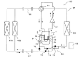
図7に示されるように、空気調和装置50は、流路切替機構68を有する。流路切替機構68は、本発明における「第2流路切替機構」に相当する。
(Usage example-2)
7 and 8 are diagrams for explaining Usage Example-2 of the accumulator according to the first embodiment. 7 and 8, the refrigerant flow during the heating operation is indicated by a solid arrow, and the refrigerant flow during the cooling operation is indicated by a dotted arrow. Further, the flow path of the four-
As shown in FIG. 7, the
流路切替機構68は、逆止弁71と、逆止弁72と、逆止弁73と、逆止弁74と、を有し、冷媒循環回路51が暖房運転を行う際と冷房運転を行う際との両方において、高圧冷媒流路4bを通過した高圧冷媒が、膨張装置64に流入するように作用する。つまり、高圧冷媒流路4bの上流側の配管と、膨張装置64の下流側の配管と、が、流路切替機構68に接続され、流路切替機構68によって、暖房運転時に室内熱交換器63a、63bから流出した冷媒が、高圧冷媒流入管5に導かれ、冷房運転時に室外熱交換器65から流出した冷媒が、高圧冷媒流入管5に導かれる。なお、流路切替機構68は、四方弁等の他の機構であってもよい。流路切替機構68が、逆止弁71と、逆止弁72と、逆止弁73と、逆止弁74と、で構成される場合には、制御系が簡素化される。
The flow
つまり、冷媒循環回路51が暖房運転を行う際と冷房運転を行う際との両方において、容器2内及び低圧冷媒流路4aを、圧縮機61に吸入される前の低圧冷媒が通過し、高圧冷媒が、高圧冷媒流路4bを通過した後に、膨張装置64に流入する。その結果、冷媒循環回路51が暖房運転を行う際と冷房運転を行う際との両方における、低圧冷媒流路4aを通過する低圧冷媒の気化及び過熱と、高圧冷媒流路4bを通過する高圧冷媒の過冷却と、を確実化できるため、冷媒循環回路51が四方弁62の切替動作によって暖房運転と冷房運転とを切り替えるものであるにも関わらず、圧縮機61の故障、運転効率の低下等を抑制することができ、また、蒸発器で生じる圧力損失の低減と蒸発器の熱交換効率の向上とを促進することができる。
That is, the low-pressure refrigerant before being sucked into the
また、冷媒循環回路51が暖房運転を行う際と冷房運転を行う際との両方において、更に、低圧冷媒流路4aを通過する低圧冷媒と高圧冷媒流路4bを通過する高圧冷媒とが、対向流となる。その結果、冷媒循環回路51が暖房運転を行う際と冷房運転を行う際との両方における、低圧冷媒流路4aを通過する低圧冷媒の気化及び過熱と、高圧冷媒流路4bを通過する高圧冷媒の過冷却と、を、更に確実化できるため、冷媒循環回路51が四方弁62の切替動作によって暖房運転と冷房運転とを切り替えるものであるにも関わらず、圧縮機61の故障、運転効率の低下等を更に抑制することができ、また、蒸発器で生じる圧力損失の低減と蒸発器の熱交換効率の向上とを、更に促進することができる。
Further, when the
なお、図8に示されるように、空気調和装置50が、流路切替機構68に換えて、膨張装置69を有していてもよい。暖房運転時には、制御装置52によって、膨張装置64の開度が、ほぼ全開に制御され、膨張装置69の開度が、例えば、室内熱交換器63a、63bから流出する冷媒が所定の過冷却度になるように制御される。冷房運転時には、制御装置52によって、膨張装置69の開度が、ほぼ全開に制御され、膨張装置64の開度が、例えば、室外熱交換器65から流出する冷媒が所定の過冷却度になるように制御される。膨張装置69は、本発明における「第2膨張装置」に相当する。
As shown in FIG. 8, the
そのような場合でも、冷媒循環回路51が暖房運転を行う際と冷房運転を行う際との両方において、高圧冷媒が、高圧冷媒流路4bを通過した後に、膨張装置69及び膨張装置64のいずれかの膨張装置に流入するため、冷媒循環回路51が四方弁62の切替動作によって暖房運転と冷房運転とを切り替えるものであるにも関わらず、冷媒循環回路51が暖房運転を行う際と冷房運転を行う際との両方において、圧縮機61の故障、運転効率の低下等を抑制することができ、また、蒸発器で生じる圧力損失の低減と蒸発器の熱交換効率の向上とを促進することができる。なお、図8では、冷房運転時に、低圧冷媒流路4aを通過する低圧冷媒と高圧冷媒流路4bを通過する高圧冷媒とが、対向流となる場合を示しているが、暖房運転時に、低圧冷媒流路4aを通過する低圧冷媒と高圧冷媒流路4bを通過する高圧冷媒とが、対向流となってもよい。
Even in such a case, both of the
実施の形態2.
以下、実施の形態2に係るアキュームレータについて説明する。
なお、実施の形態1に係るアキュームレータと重複する説明は、適宜簡略化又は省略している。
<アキュームレータの構成及び作用>
以下に、実施の形態2に係るアキュームレータの構成及び作用について説明する。
図9は、実施の形態2に係るアキュームレータの、構成及び作用を説明するための図である。
Hereinafter, the accumulator according to the second embodiment will be described.
In addition, the description which overlaps with the accumulator which concerns on
<Configuration and operation of accumulator>
The configuration and operation of the accumulator according to
FIG. 9 is a diagram for explaining the configuration and operation of the accumulator according to the second embodiment.
図9に示されるように、橋渡し管16は、その内部に、アパーチャ16aを有する。アパーチャ16aの開口面積、つまり、流路断面積は、第1管11と第1外管14との間の隙間の流路断面積及び第2管13と第2外管15との間の隙間の流路断面積と比較して、小さい。そのように構成されることで、アパーチャ16aで生じる減圧によって、第1管11と第1外管14との間の隙間を通過する高圧冷媒と、第2管13と第2外管15との間の隙間を通過する高圧冷媒と、の圧力差を生じさせることができ、例えば、下流側の隙間を形成する第1外管14又は第2外管15の肉厚を薄くする等によって、上流側の隙間の通過によって冷却されている、下流側の隙間を通過する高圧冷媒と、容器2内の低圧冷媒と、の間の熱伝達性能を向上させること等が可能となって、容器2内の低圧冷媒の気化及び過熱と、高圧冷媒流路4bを通過する高圧冷媒の過冷却と、を、更に促進させることが可能となる。
As shown in FIG. 9, the bridging
特に、高圧冷媒流路4bを通過する高圧冷媒が、低圧冷媒流路4aを通過する低圧冷媒と対向流である、つまり、第2管13と第2外管15との間の隙間から第1管11と第1外管14との間の隙間に流入する場合には、第1管11の周辺の低圧冷媒の気化が促進されて、第1管11の上方側の端部から液冷媒が流入することの抑制が更に確実化される。
In particular, the high-pressure refrigerant passing through the high-pressure
なお、橋渡し管16が、アパーチャ16aを有さず、橋渡し管16自体の流路断面積が、第1管11と第1外管14との間の隙間の流路断面積及び第2管13と第2外管15との間の隙間の流路断面積と比較して、小さくてもよい。また、橋渡し管16が、アパーチャ16aではなく、流量調整弁を有していてもよい。つまり、橋渡し管16の少なくとも一部の流路断面積が、第1管11と第1外管14との間の隙間の流路断面積及び第2管13と第2外管15との間の隙間の流路断面積と比較して、小さければよい。
Note that the bridging
実施の形態3.
以下、実施の形態3に係るアキュームレータについて説明する。
なお、実施の形態1及び実施の形態2に係るアキュームレータと重複する説明は、適宜簡略化又は省略している。
<アキュームレータの構成及び作用>
以下に、実施の形態3に係るアキュームレータの構成及び作用について説明する。
図10は、実施の形態3に係るアキュームレータの、構成及び作用を説明するための図である。
Hereinafter, the accumulator according to the third embodiment will be described.
In addition, the description which overlaps with the accumulator which concerns on
<Configuration and operation of accumulator>
The configuration and operation of the accumulator according to the third embodiment will be described below.
FIG. 10 is a diagram for explaining the configuration and operation of the accumulator according to the third embodiment.
図10に示されるように、橋渡し管16は、フィン16bを有する。そのように構成されることで、低圧冷媒流出体4の熱交換性能を向上させることが可能となって、容器2内の低圧冷媒の気化及び過熱と、高圧冷媒流路4bを通過する高圧冷媒の過冷却と、を更に促進させることが可能となる。なお、第1外管14及び第2外管15の少なくとも一方が、フィンを有していてもよい。第1外管14がフィンを有する場合には、第1管11の周辺の低圧冷媒の気化が促進されて、第1管11の上方側の端部から液冷媒が流入することの抑制が更に確実化される。
As shown in FIG. 10, the bridging
フィン16bの下端部は、油戻し穴17及びストロー管18の先端部と比較して上側に位置する。そのように構成されることで、フィン16bによって、容器2の底部に滞留する油、例えば圧縮機の潤滑油等と、液冷媒と、が加熱されることが抑制されて、分離されない油成分が増加することが抑制され、容器2内における、油、例えば圧縮機の潤滑油等と、液冷媒と、の二層化が促進されることとなる。その結果、アキュームレータ1の油、例えば圧縮機の潤滑油等の返油性能が向上されて、圧縮機等の故障等を抑制することの確実性が更に向上される。
The lower end portion of the
以上、実施の形態1〜実施の形態3について説明したが、本発明は各実施の形態の説明に限定されない。例えば、実施の形態の全て又は一部を組み合わせることも可能である。 Although the first to third embodiments have been described above, the present invention is not limited to the description of each embodiment. For example, all or some of the embodiments can be combined.
1 アキュームレータ、2 容器、2a キャップ、2b シェル、3 低圧冷媒流入管、4 低圧冷媒流出体、4a 低圧冷媒流路、4b 高圧冷媒流路、5 高圧冷媒流入管、6 高圧冷媒流出管、11 第1管、12 U字管、13 第2管、14 第1外管、15 第2外管、16 橋渡し管、16a アパーチャ、16b フィン、17 油戻し穴、18 ストロー管、21、22 支持部材、21a、22a 外周面、50 空気調和装置、51 冷媒循環回路、52 制御装置、61 圧縮機、62 四方弁、63a、63b 室内熱交換器、64 膨張装置、65 室外熱交換器、66、67 延長配管、68 流路切替機構、69 膨張装置、71〜74 逆止弁。 1 accumulator, 2 container, 2a cap, 2b shell, 3 low pressure refrigerant inflow pipe, 4 low pressure refrigerant outflow body, 4a low pressure refrigerant flow path, 4b high pressure refrigerant flow path, 5 high pressure refrigerant inflow pipe, 6 high pressure refrigerant outflow pipe, 11 1 pipe, 12 U-shaped pipe, 13 second pipe, 14 first outer pipe, 15 second outer pipe, 16 bridging pipe, 16a aperture, 16b fin, 17 oil return hole, 18 straw pipe, 21, 22 support member, 21a, 22a outer peripheral surface, 50 air conditioner, 51 refrigerant circulation circuit, 52 control device, 61 compressor, 62 four-way valve, 63a, 63b indoor heat exchanger, 64 expansion device, 65 outdoor heat exchanger, 66, 67 extension Piping, 68 flow path switching mechanism, 69 expansion device, 71-74 check valve.
Claims (14)
前記容器内に前記低圧冷媒を流入させる低圧冷媒流入管と、
前記容器内に、上流側管状部、前記上流側管状部の下方側の端部に連通する低圧冷媒折返部、及び、前記低圧冷媒折返部に下方側の端部が連通する下流側管状部、を有し、前記容器内の前記低圧冷媒を、前記上流側管状部の上方側の端部から前記下流側管状部の上方側の端部まで通過させて、前記容器外に流出させる低圧冷媒流出体と、
を備え、
前記上流側管状部の少なくとも一部は、第1外管によって隙間を有する状態で覆われ、
前記下流側管状部の少なくとも一部は、第2外管によって隙間を有する状態で覆われ、
前記第1外管と前記第2外管とは、橋渡し管によって連通され、
前記上流側管状部と前記第1外管との間の前記隙間、前記橋渡し管、及び、前記下流側管状部と前記第2外管との間の前記隙間、を高圧冷媒が通過し、
前記橋渡し管の少なくとも一部の流路断面積は、前記上流側管状部と前記第1外管との間の前記隙間の流路断面積、及び、前記下流側管状部と前記第2外管との間の前記隙間の流路断面積と比較して、小さい、
ことを特徴とするアキュームレータ。 A container enclosing a low-pressure refrigerant;
A low-pressure refrigerant inflow pipe for allowing the low-pressure refrigerant to flow into the container;
In the container, an upstream tubular portion, a low pressure refrigerant folded portion communicating with a lower end portion of the upstream tubular portion, and a downstream tubular portion communicated with a lower end portion of the low pressure refrigerant folded portion, Low-pressure refrigerant outflow that allows the low-pressure refrigerant in the container to pass from the upper end of the upstream tubular portion to the upper end of the downstream tubular portion to flow out of the container Body,
With
At least a part of the upstream tubular portion is covered with a gap by the first outer tube,
At least a part of the downstream tubular portion is covered with a gap by the second outer tube,
The first outer pipe and the second outer pipe are communicated by a bridge pipe,
High-pressure refrigerant passes through the gap between the upstream tubular portion and the first outer pipe, the bridging pipe, and the gap between the downstream tubular section and the second outer pipe,
The flow passage cross-sectional area of at least a part of the bridging pipe includes a flow passage cross-sectional area of the gap between the upstream tubular portion and the first outer tube, and a downstream tubular portion and the second outer tube. Smaller than the flow path cross-sectional area of the gap between
An accumulator characterized by that.
一方の端部が、前記上流側管状部の上方側の端部から流入する前記低圧冷媒が通過する流路のうちの、前記第1外管及び前記第2外管によって覆われていない領域に連通され、他方の端部が、前記容器内の下方に位置する油流入流路を有する、
ことを特徴とする請求項1に記載のアキュームレータ。 The low-pressure refrigerant effluent is
One end of the flow path through which the low-pressure refrigerant flowing from the upper end of the upstream tubular portion passes is not covered by the first outer tube and the second outer tube. Communicated and the other end has an oil inflow channel located below the container,
The accumulator according to claim 1.
ことを特徴とする請求項2に記載のアキュームレータ。 The bridging pipe is located on the upper side as compared with the other end of the oil inflow channel.
The accumulator according to claim 2.
前記油流入流路の前記一方の端部は、前記下流側の領域に連通された、
ことを特徴とする請求項2又は3に記載のアキュームレータ。 The downstream region of the downstream tubular portion is not covered by the second outer tube,
The one end of the oil inflow channel is communicated with the downstream region,
The accumulator according to claim 2 or 3, characterized in that.
ことを特徴とする請求項1〜4のいずれか一項に記載のアキュームレータ。 The length of the first outer tube is longer than the length of the second outer tube,
The accumulator as described in any one of Claims 1-4 characterized by the above-mentioned.
ことを特徴とする請求項1〜5のいずれか一項に記載のアキュームレータ。 The upstream tubular portion, the low-pressure refrigerant folded portion, and the downstream tubular portion are separate members.
The accumulator as described in any one of Claims 1-5 characterized by the above-mentioned.
ことを特徴とする請求項1〜6のいずれか一項に記載のアキュームレータ。 The low-pressure refrigerant and the high-pressure refrigerant pass through an opening formed in the upper surface of the container, and flow into and out of the container.
The accumulator as described in any one of Claims 1-6 characterized by the above-mentioned.
前記アキュームレータは、請求項1〜7のいずれか一項に記載のアキュームレータであり、
前記アキュームレータの前記低圧冷媒が通過する流路の下流側の配管に、前記圧縮機が接続され、
前記アキュームレータの前記高圧冷媒が通過する流路の下流側の配管に、前記第1膨張装置が接続された、
ことを特徴とする空気調和装置。 A compressor, a first flow path switching mechanism, an indoor heat exchanger, a first expansion device, an outdoor heat exchanger, and an accumulator are connected by piping, and heating operation and cooling operation are performed by switching operation of the first flow path switching mechanism. Has a refrigerant circuit that can be switched,
The accumulator is an accumulator according to any one of claims 1 to 7,
The compressor is connected to a pipe on the downstream side of the flow path through which the low-pressure refrigerant of the accumulator passes,
The first expansion device is connected to a pipe on the downstream side of the flow path through which the high-pressure refrigerant of the accumulator passes.
An air conditioner characterized by that.
前記アキュームレータの前記低圧冷媒が通過する流路の下流側の配管に、前記圧縮機が接続され、
前記アキュームレータの前記高圧冷媒が通過する流路の下流側の配管に、前記第1膨張装置が接続された、
ことを特徴とする請求項8に記載の空気調和装置。 At least when the refrigerant circulation circuit performs heating operation,
The compressor is connected to a pipe on the downstream side of the flow path through which the low-pressure refrigerant of the accumulator passes,
The first expansion device is connected to a pipe on the downstream side of the flow path through which the high-pressure refrigerant of the accumulator passes.
The air conditioning apparatus according to claim 8 .
前記アキュームレータの前記低圧冷媒が通過する流路の下流側の配管に、前記圧縮機が接続され、
前記アキュームレータの前記高圧冷媒が通過する流路の下流側の配管に、前記第1膨張装置が接続された、
ことを特徴とする請求項9に記載の空気調和装置。 Furthermore, when the refrigerant circuit is in cooling operation,
The compressor is connected to a pipe on the downstream side of the flow path through which the low-pressure refrigerant of the accumulator passes,
The first expansion device is connected to a pipe on the downstream side of the flow path through which the high-pressure refrigerant of the accumulator passes.
The air conditioner according to claim 9 .
ことを特徴とする請求項10に記載の空気調和装置。 A pipe on the upstream side of the flow path through which the high-pressure refrigerant of the accumulator passes and a pipe on the downstream side of the first expansion device are connected to the outdoor heat exchanger via the second flow path switching mechanism, Communicated with the indoor heat exchanger,
The air conditioning apparatus according to claim 10 .
ことを特徴とする請求項11に記載の空気調和装置。 The second flow path switching mechanism has four check valves.
The air conditioning apparatus according to claim 11 .
ことを特徴とする請求項12に記載の空気調和装置。 The air conditioner according to claim 12 , wherein a second expansion device is connected to a pipe on the upstream side of the flow path through which the high-pressure refrigerant of the accumulator passes.
ことを特徴とする請求項8〜13のいずれか一項に記載の空気調和装置。 In the accumulator, the low-pressure refrigerant passing through the low-pressure refrigerant effluent and the high-pressure refrigerant are counterflows.
The air conditioning apparatus according to any one of claims 8 to 13 , wherein
Priority Applications (8)
| Application Number | Priority Date | Filing Date | Title |
|---|---|---|---|
| JP2013262662A JP6184314B2 (en) | 2013-12-19 | 2013-12-19 | Accumulator and air conditioner |
| PCT/JP2014/076204 WO2015093126A1 (en) | 2013-12-19 | 2014-09-30 | Accumulator, air conditioning device, and method for manufacturing accumulator |
| EP14870798.7A EP3086056A4 (en) | 2013-12-19 | 2014-09-30 | Accumulator, air conditioning device, and method for manufacturing accumulator |
| US15/026,630 US10228171B2 (en) | 2013-12-19 | 2014-09-30 | Accumulator, air-conditioning apparatus and method for manufacturing accumulator |
| MX2016008132A MX2016008132A (en) | 2013-12-19 | 2014-09-30 | Accumulator, air conditioning device, and method for manufacturing accumulator. |
| AU2014368147A AU2014368147B2 (en) | 2013-12-19 | 2014-09-30 | Accumulator, air-conditioning apparatus and method for manufacturing accumulator |
| CN201420802769.0U CN204494925U (en) | 2013-12-19 | 2014-12-17 | Reservoir and aircondition |
| CN201410785635.7A CN104729165B (en) | 2013-12-19 | 2014-12-17 | Accumulator, air conditioning device, and method for manufacturing accumulator |
Applications Claiming Priority (1)
| Application Number | Priority Date | Filing Date | Title |
|---|---|---|---|
| JP2013262662A JP6184314B2 (en) | 2013-12-19 | 2013-12-19 | Accumulator and air conditioner |
Publications (3)
| Publication Number | Publication Date |
|---|---|
| JP2015117915A JP2015117915A (en) | 2015-06-25 |
| JP2015117915A5 JP2015117915A5 (en) | 2015-08-27 |
| JP6184314B2 true JP6184314B2 (en) | 2017-08-23 |
Family
ID=53402483
Family Applications (1)
| Application Number | Title | Priority Date | Filing Date |
|---|---|---|---|
| JP2013262662A Expired - Fee Related JP6184314B2 (en) | 2013-12-19 | 2013-12-19 | Accumulator and air conditioner |
Country Status (7)
| Country | Link |
|---|---|
| US (1) | US10228171B2 (en) |
| EP (1) | EP3086056A4 (en) |
| JP (1) | JP6184314B2 (en) |
| CN (2) | CN104729165B (en) |
| AU (1) | AU2014368147B2 (en) |
| MX (1) | MX2016008132A (en) |
| WO (1) | WO2015093126A1 (en) |
Families Citing this family (9)
| Publication number | Priority date | Publication date | Assignee | Title |
|---|---|---|---|---|
| WO2015198475A1 (en) * | 2014-06-27 | 2015-12-30 | 三菱電機株式会社 | Refrigeration cycle device |
| JP6507071B2 (en) * | 2015-09-28 | 2019-04-24 | 東芝キヤリア株式会社 | Gas-liquid separator and refrigeration cycle apparatus |
| WO2017145826A1 (en) * | 2016-02-24 | 2017-08-31 | 旭硝子株式会社 | Refrigeration cycle device |
| CN206207818U (en) * | 2016-10-31 | 2017-05-31 | 广东美芝精密制造有限公司 | Reservoir and the compressor assembly with it |
| US10845106B2 (en) * | 2017-12-12 | 2020-11-24 | Rheem Manufacturing Company | Accumulator and oil separator |
| CN111750577B (en) * | 2019-03-28 | 2022-08-30 | 浙江三花汽车零部件有限公司 | Gas-liquid separator |
| DE102021204471A1 (en) * | 2020-05-05 | 2021-11-11 | Mahle International Gmbh | Intermediate refrigerant storage tank and refrigerant system |
| DE102022118622A1 (en) | 2022-07-26 | 2024-02-01 | Audi Aktiengesellschaft | Refrigeration system for supercritical refrigerant with additional refrigerant storage and integrated heat exchanger for a motor vehicle, motor vehicle with such a refrigeration system |
| CN116222039B (en) * | 2023-05-10 | 2023-08-08 | 格兰立方能源科技(江苏)有限公司 | Liquid separating reservoir for air conditioner and refrigerating system thereof |
Family Cites Families (11)
| Publication number | Priority date | Publication date | Assignee | Title |
|---|---|---|---|---|
| JPS54108454U (en) * | 1978-01-18 | 1979-07-31 | ||
| JPS56144279U (en) * | 1980-04-01 | 1981-10-30 | ||
| JPS6183849A (en) * | 1984-10-01 | 1986-04-28 | 日新興業株式会社 | Method and device for vaporizing refrigerant for vapor biser |
| US6681597B1 (en) * | 2002-11-04 | 2004-01-27 | Modine Manufacturing Company | Integrated suction line heat exchanger and accumulator |
| JP2005098581A (en) * | 2003-09-24 | 2005-04-14 | Hoshizaki Electric Co Ltd | Freezing circuit and cooling device using the freezing circuit |
| WO2006005171A1 (en) * | 2004-07-09 | 2006-01-19 | Junjie Gu | Refrigeration system |
| CN1292218C (en) * | 2005-02-08 | 2006-12-27 | 华南理工大学 | Non-pump sorption refrigerator |
| JP2006273049A (en) * | 2005-03-28 | 2006-10-12 | Calsonic Kansei Corp | Vehicular air conditioner |
| JP4987685B2 (en) * | 2007-12-19 | 2012-07-25 | 三菱電機株式会社 | Double tube heat exchanger, method for manufacturing the same, and heat pump system including the same |
| CN102470729A (en) * | 2009-10-13 | 2012-05-23 | 昭和电工株式会社 | Intermediate heat exchanger |
| JP2011163671A (en) * | 2010-02-10 | 2011-08-25 | Mitsubishi Electric Corp | Liquid receiver and refrigerating cycle device using the same |
-
2013
- 2013-12-19 JP JP2013262662A patent/JP6184314B2/en not_active Expired - Fee Related
-
2014
- 2014-09-30 MX MX2016008132A patent/MX2016008132A/en active IP Right Grant
- 2014-09-30 US US15/026,630 patent/US10228171B2/en not_active Expired - Fee Related
- 2014-09-30 EP EP14870798.7A patent/EP3086056A4/en active Pending
- 2014-09-30 AU AU2014368147A patent/AU2014368147B2/en not_active Ceased
- 2014-09-30 WO PCT/JP2014/076204 patent/WO2015093126A1/en active Application Filing
- 2014-12-17 CN CN201410785635.7A patent/CN104729165B/en not_active Expired - Fee Related
- 2014-12-17 CN CN201420802769.0U patent/CN204494925U/en not_active Expired - Fee Related
Also Published As
| Publication number | Publication date |
|---|---|
| EP3086056A4 (en) | 2017-07-19 |
| EP3086056A1 (en) | 2016-10-26 |
| US20160245563A1 (en) | 2016-08-25 |
| JP2015117915A (en) | 2015-06-25 |
| CN104729165B (en) | 2017-04-12 |
| AU2014368147B2 (en) | 2017-08-03 |
| CN204494925U (en) | 2015-07-22 |
| US10228171B2 (en) | 2019-03-12 |
| CN104729165A (en) | 2015-06-24 |
| MX2016008132A (en) | 2016-10-13 |
| WO2015093126A1 (en) | 2015-06-25 |
Similar Documents
| Publication | Publication Date | Title |
|---|---|---|
| JP6184314B2 (en) | Accumulator and air conditioner | |
| JPH0835744A (en) | Refrigerant condenser integral with liquid receiver | |
| ES2688420T3 (en) | Start-up procedure for refrigerant systems that have microchannel condenser and reheat cycle | |
| JP6341099B2 (en) | Refrigerant evaporator | |
| JP5975971B2 (en) | Heat exchanger and refrigeration cycle apparatus | |
| EP2787314B1 (en) | Double-pipe heat exchanger and air conditioner using same | |
| JP6236541B2 (en) | Gas-liquid separator and refrigeration cycle apparatus | |
| JPWO2018225252A1 (en) | Heat exchanger and refrigeration cycle device | |
| JP2014224670A (en) | Double-pipe heat exchanger | |
| EP2980510B1 (en) | Expansion valve and cooling cycle device using same | |
| JP5713312B2 (en) | Refrigeration cycle equipment | |
| JP2017172906A (en) | Heat exchanger | |
| JP2017026248A (en) | Double-pipe heat exchanger | |
| JP2007333319A (en) | Heat exchanger | |
| JP2015001367A (en) | Gas-liquid separator, and air conditioner having the same mounted thereon | |
| EP3667199B1 (en) | Heat exchanger with filter, for refrigerant fluid loop | |
| JP6780516B2 (en) | Liquid reservoir | |
| JP6507071B2 (en) | Gas-liquid separator and refrigeration cycle apparatus | |
| WO2023238234A1 (en) | Heat exchanger | |
| JP5823078B2 (en) | Expansion valve and refrigeration cycle apparatus using the same | |
| KR102136749B1 (en) | An air conditioner | |
| JP2014035169A (en) | Intermediate heat exchanger | |
| JP6658242B2 (en) | Heat exchanger | |
| JP2015017762A (en) | Double-tube type heat exchanger | |
| WO2018066025A1 (en) | Air conditioning device |
Legal Events
| Date | Code | Title | Description |
|---|---|---|---|
| A521 | Request for written amendment filed |
Free format text: JAPANESE INTERMEDIATE CODE: A523 Effective date: 20150710 |
|
| A621 | Written request for application examination |
Free format text: JAPANESE INTERMEDIATE CODE: A621 Effective date: 20150710 |
|
| A131 | Notification of reasons for refusal |
Free format text: JAPANESE INTERMEDIATE CODE: A131 Effective date: 20160510 |
|
| A521 | Request for written amendment filed |
Free format text: JAPANESE INTERMEDIATE CODE: A523 Effective date: 20160707 |
|
| A131 | Notification of reasons for refusal |
Free format text: JAPANESE INTERMEDIATE CODE: A131 Effective date: 20161206 |
|
| A521 | Request for written amendment filed |
Free format text: JAPANESE INTERMEDIATE CODE: A523 Effective date: 20170120 |
|
| TRDD | Decision of grant or rejection written | ||
| A01 | Written decision to grant a patent or to grant a registration (utility model) |
Free format text: JAPANESE INTERMEDIATE CODE: A01 Effective date: 20170627 |
|
| A61 | First payment of annual fees (during grant procedure) |
Free format text: JAPANESE INTERMEDIATE CODE: A61 Effective date: 20170725 |
|
| R150 | Certificate of patent or registration of utility model |
Ref document number: 6184314 Country of ref document: JP Free format text: JAPANESE INTERMEDIATE CODE: R150 |
|
| R250 | Receipt of annual fees |
Free format text: JAPANESE INTERMEDIATE CODE: R250 |
|
| LAPS | Cancellation because of no payment of annual fees |