JP6182334B2 - Manufacturing method of scribing wheel - Google Patents
Manufacturing method of scribing wheel Download PDFInfo
- Publication number
- JP6182334B2 JP6182334B2 JP2013053996A JP2013053996A JP6182334B2 JP 6182334 B2 JP6182334 B2 JP 6182334B2 JP 2013053996 A JP2013053996 A JP 2013053996A JP 2013053996 A JP2013053996 A JP 2013053996A JP 6182334 B2 JP6182334 B2 JP 6182334B2
- Authority
- JP
- Japan
- Prior art keywords
- groove
- scribing wheel
- blade
- holder
- scribing
- Prior art date
- Legal status (The legal status is an assumption and is not a legal conclusion. Google has not performed a legal analysis and makes no representation as to the accuracy of the status listed.)
- Expired - Fee Related
Links
Images


Description
本発明は、ガラス基板等の脆性材料基板にスクライブラインを形成するためのスクライビングホイールの製造方法に関する。 The present invention relates to a method of manufacturing a scribing wheel for forming a scribing line on a brittle material substrate such as a glass substrate.
脆性材料基板を分断するスクライビングホイールとして、このスクライビングホイールの稜線部分の刃先にレーザ光を照射することで、この刃先に複数の溝を形成することが知られている。 As a scribing wheel for cutting a brittle material substrate, it is known that a plurality of grooves are formed in the cutting edge by irradiating the cutting edge of the ridge line portion of the scribing wheel with laser light.
特許文献1には、モータの駆動軸に軸孔が装着されて回転駆動されるカッターホイールのV字形状となる刃先を含む両側の傾斜面に向けて、レーザ加工機からのパルスレーザ光を照射して溶融溝を形成するカッターホイールの製造方法が開示されている。
しかしながら、レーザ光を照射して溝を形成する場合、溝を深くするためには、レーザ光をより深部まで照射する必要がある。このため、レーザ光を照射する方法では、深い溝(3μm程度以上)の形成が困難である。これに対して、砥石を用いて溝を形成する方法では、他の方法により溝を形成する場合と比較して、より容易に溝を深くすることができる。 However, when the groove is formed by irradiating the laser beam, it is necessary to irradiate the laser beam to a deeper portion in order to deepen the groove. For this reason, it is difficult to form a deep groove (about 3 μm or more) by the laser beam irradiation method. On the other hand, in the method of forming a groove using a grindstone, the groove can be deepened more easily than in the case where the groove is formed by another method.
一方で、砥石により溝を形成すると、溝の端部(エッジ)が鋭くなり易く、その角度が急になり易い。溝の端部の角は、刃先が脆性材料基板と接触した際に、摩耗し易い。溝の端部の角が摩耗すると、この角の摩耗の前後で脆性材料基板を分断する性能が変化することとなる。 On the other hand, when a groove is formed with a grindstone, the end (edge) of the groove is likely to be sharp, and the angle tends to be steep. The corners of the end of the groove are easily worn when the cutting edge comes into contact with the brittle material substrate. When the corner of the groove end wears, the ability to sever the brittle material substrate changes before and after the wear of the corner.
本発明は、従来のスクライビングホイールと比較して深い溝の形成を容易にしつつ、基板を分断する性能の変化を抑制したスクライビングホイールの製造方法を提供することを目的とする。
The present invention, while facilitating formation of deep grooves in comparison to conventional scribing wheel, and an object thereof is to provide a method for manufacturing a scribing wheel obtained by a variation restriction of the ability to divide the substrate.
本発明の一つの態様に係るスクライビングホイールの製造方法は、基材の周縁に砥石を用いて溝を形成する工程と、前記溝の周方向に対する端部を面取りする工程と、を含み、面取りを、レーザ加工により行う。
A method of manufacturing a scribing wheel according to one aspect of the present invention includes a step of forming a groove using a grindstone on a peripheral edge of a base material, and a step of chamfering an end portion of the groove in the circumferential direction. Is performed by laser processing.
本発明の一つの態様に係るスクライビングホイールの製造方法によれば、溝の周方向に対する端部に面取部が形成されていない場合と比較して、深い溝の形成を容易にしつつ、基板を分断する性能の変化を抑制したスクライビングホイールの製造方法を提供することができる。 According to the method for manufacturing a scribing wheel according to one aspect of the present invention, it is possible to form a substrate while facilitating formation of a deep groove as compared with a case where a chamfered portion is not formed at an end portion in the circumferential direction of the groove. It is possible to provide a method of manufacturing a scribing wheel that suppresses a change in the performance to be divided.
以下、本発明の実施形態を図面を用いて説明する。ただし、以下に示す実施形態は、本発明の技術思想を具体化するための一例を示すものであり、本発明をこの実施形態に特定することを意図するものではない。本発明は、特許請求の範囲に含まれるその他の実施形態のものにも適応し得るものである。 Hereinafter, embodiments of the present invention will be described with reference to the drawings. However, the embodiment shown below shows an example for embodying the technical idea of the present invention, and is not intended to specify the present invention to this embodiment. The invention is also applicable to other embodiments within the scope of the claims.
[第一実施形態]
実施形態に係るスクライブ装置10の概略図を図1に示す。スクライブ装置10は、移動台11を備えている。移動台11は、ボールネジ13と螺合されており、モータ14の駆動によりこのボールネジ13が回転することで、一対の案内レール12a、12bに沿ってy軸方向に移動するようになっている。
[First embodiment]
A schematic diagram of a
移動台11の上面には、モータ15が設置されている。モータ15は、上部に位置するテーブル16をxy平面で回転させて所定角度に位置決めするためのものである。被切断物としての脆性材料基板17は、テーブル16上に載置され、図示しない真空吸引手段などによって保持される。スクライブの対象となる脆性材料基板17としては、ガラス基板、低温焼成セラミックスや高温焼成セラミックスからなるセラミック基板、シリコン基板、化合物半導体基板、サファイア基板、石英基板等が挙げられる。また、脆性材料基板17はその表面又は内部に、薄膜或いは半導体材料を付着させたり含ませたりしたものであってもよい。脆性材料基板17は、その表面に脆性材料に該当しない薄膜等が付着されていても構わない。
A
スクライブ装置10は、テーブル16に載置された脆性材料基板17の上方に、この脆性材料基板17の表面に形成されたアライメントマークを撮像する二台のCCDカメラ18を備えている。移動台11とその上部のテーブル16とを跨ぐように、ブリッジ19がx軸方向に沿うようにして支柱20a、20bによって架設されている。
The
ブリッジ19にはガイド22が取り付けられており、スクライブヘッド21はこのガイド22に案内されてx軸方向に移動可能に設置されている。スクライブヘッド21には、ホルダージョイント23を介してホルダーユニット30が取り付けられている。
A
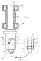
図2には、ホルダーユニット30が取り付けられたホルダージョイント23の正面図が示されている。なお、図2には、ホルダージョイント23の正面図が示されるとともに、回転軸部23aに取り付けられたベアリング25a、25bとスペーサ25cの断面図が併せて示されている。
FIG. 2 shows a front view of the
ホルダージョイント23は略円柱状をしており、回転軸部23aと、円柱形のジョイント部23bとで構成されている。ホルダージョイント23がスクライブヘッド21に装着された状態においては、回転軸部23aが二つのベアリング25a、25bに円筒形のスペーサ25cを介して取り付けられ、このホルダージョイント23は回動自在に保持される。
The
ジョイント部23bの下端には円形の開口26が形成され、この開口26の上部にはマグネット27が埋設されている。開口26を介して、ホルダーユニット30のホルダー24が着脱自在に取り付けられる。ホルダーユニット30は、ホルダー24と、ピン33と、スクライビングホイール40とを備える。
A
ホルダー24は略円柱形の金属等からなり、その下端側には平坦部29a、29bが形成されている。なお、図2において、ホルダーユニット30の下端側を拡大している図は、このホルダーユニット30を矢印Aで示す横方向から観察した場合の拡大図を示している。
The
平坦部29aと平坦部29bとの間には、スクライビングホイール40を保持するための保持溝31が形成されている。平坦部29a、29bにはそれぞれ、スクライビングホイール40を固定するために孔状のピン孔32が形成されている。ピン孔32及びスクライビングホイール40にピン33を貫通させることで、このスクライビングホイール40がホルダー24に対して回転自在に取り付けられる。
A
ホルダー24の上端側には、位置決め用の取付部34が形成されている。取付部34はホルダー24を切り欠いて形成されており、傾斜部34aと平坦部34bとを有している。
A
ホルダージョイント23にホルダーユニット30を装着する際は、このホルダーユニット30を開口26に向けて取付部34側から挿入する。その際、ホルダー24の上端側の金属部分がマグネット27によって引き寄せられ、取付部34の傾斜部34aが開口26の内部を通る平行ピン28と接触し、位置決めが行われ、ホルダー24はホルダージョイント23に固定される。反対に、ホルダージョイント23からホルダーユニット30を取り外す際は、ホルダー24を下方へ引く抜くことで、容易に取り外すことができる。
When attaching the
ホルダーユニット30のスクライビングホイール40は、消耗品であるため定期的な交換が必要となる。本実施形態においては、ホルダージョイント23を介してホルダーユニット30がスクライブヘッド21に装着されているので、このホルダーユニット30の着脱が容易に行われる。このため、スクライビングホイール40をホルダー24から取り外すことなく、これらスクライビングホイール40とホルダー24とが一体として扱われる。また、ホルダーユニット30そのものを交換するようにしてもよい。したがって、スクライビングホイール40の交換作業が容易に行われることとなる。
Since the
次に、スクライビングホイール40の詳細について説明する。
図3(a)、(b)、(c)にはそれぞれ、スクライビングホイール40の側面図、正面図、拡大側面図が示されている。なお、図3(c)の拡大側面図は図3(a)の円Bで示した部分である。
スクライビングホイール40は、本体部41と、刃42と、刃先43と、溝部44とを有している。
Next, the details of the
3A, 3B, and 3C show a side view, a front view, and an enlarged side view of the
The
本体部41は、円板状である。本体部41の中心付近には、この本体部41を回転軸方向に対して貫通する貫通孔45が形成されている。貫通孔45にピン33が挿入されることで、スクライビングホイール40はこのピン33を介してホルダー24に回転自在に保持される。本体部41の外周に、円環状の刃42が形成されている。
The
刃42は、回転軸を中心とした同心円状の内周及び外周により形成される円環状体である。刃42は正面視で略V字状となっており、回転軸方向に対する刃42の厚さは、稜線部分となる刃先43に向かうに従って徐々に小さくなっている。
The
刃先43は、刃42の最外周部に沿って設けられている。刃42の最外周部には、刃先43と溝部44とが交互に等ピッチで形成されている。
The
溝部44は、刃先43よりも本体部41の中心側(貫通孔45側)に窪んだ溝46と、本体部41の周方向に対するこの溝46の両端部に形成された平面状の面取部47とにより構成されている。面取部47は、角が緩やかな部分であり、例えば角を面取りすることにより形成される。溝46と刃先43とが面取部47を介して連続している場合、溝46と刃先43とが面取部47を介さずに連続している場合と比較して、溝46の端部の角度が緩やかになる。このため、スクライビング中に刃42の角部の形状が変化し難く、脆性材料基板17を分断する性能の変化が抑制される。
The
また、溝46は、本体部41の周方向に対して垂直な方向の端部(スクライビングホイール40の回転軸方向に対する端部)である縁48が面取りされており、この縁48に面取部48aが形成されている。縁48に対しても面取り加工を施すようにすることで、溝46の形状の安定性がより向上する。
The
スクライビングホイール40は、超硬合金や焼結ダイヤモンドから形成される。または、超硬合金等の基材にダイヤモンド等の硬質材料の膜をコーティングしたものを用いることができる。例えば、焼結ダイヤモンド製のスクライビングホイール40は主として、ダイヤモンド粒子と、残部の添加剤及び結合材からなる結合相とから作られている。
The
ダイヤモンド粒子の平均粒子径は1.5μm以下のものが用いられている。焼結ダイヤモンド中におけるダイヤモンドの含有量は、75.0〜90.0vol%の範囲とすることが好ましい。 Diamond particles having an average particle diameter of 1.5 μm or less are used. The diamond content in the sintered diamond is preferably in the range of 75.0 to 90.0 vol%.
添加剤としては例えば、タングステン、チタン、ニオブ、タンタルより選ばれる少なくとも1種以上の元素の超微粒子炭化物が好適に用いられる。焼結ダイヤモンド中における超微粒子炭化物の含有量は3.0〜10.0vol%の範囲であり、この超微粒子炭化物は1.0〜4.0vol%の炭化チタンと、残部の炭化タングステンとを含む。 For example, an ultrafine carbide of at least one element selected from tungsten, titanium, niobium, and tantalum is preferably used as the additive. The content of ultrafine carbide in the sintered diamond is in the range of 3.0 to 10.0 vol%, and the ultrafine carbide includes 1.0 to 4.0 vol% titanium carbide and the balance tungsten carbide. .
結合材としては、通常、鉄族元素が好適に用いられる。鉄族元素としては、例えばコバルトやニッケル、鉄等が挙げられ、この中でもコバルトが好適である。また、焼結ダイヤモンド中における結合材の含有量は、好ましくはダイヤモンド及び超微粒子炭化物の残部であり、さらに好ましくは3.0〜20.5vol%の範囲である。 Usually, an iron group element is suitably used as the binder. Examples of the iron group element include cobalt, nickel, iron and the like, and among these, cobalt is preferable. Further, the content of the binder in the sintered diamond is preferably the balance of diamond and ultrafine carbide, and more preferably in the range of 3.0 to 20.5 vol%.
スクライビングホイール40の寸法について説明する。
スクライビングホイール40の外径Dmは1.0〜10.0mm、好ましくは1.0〜5.0mmの範囲である。スクライビングホイール40の外径Dmが1.0mmより小さい場合には、スクライビングホイール40の取り扱い性が低下する。一方、スクライビングホイール40の外径Dmが10.0mmより大きい場合には、スクライブ時の垂直クラックが脆性材料基板17に対して十分に深く形成されないことがある。
The dimensions of the
The outer diameter Dm of the
スクライビングホイール40の厚さThは、0.4〜1.2mm、好ましくは0.4〜1.1mmの範囲である。スクライビングホイール40の厚さThが0.4mmより小さい場合には、加工性及び取り扱い性が低下することがある。一方、スクライビングホイール40の厚さThが1.2mmより大きい場合には、スクライビングホイール40の材料及び製造のためのコストが高くなる。
The thickness Th of the
刃42の刃先角θ1は通常鈍角であり、90≦θ1≦160(deg)、好ましくは90≦θ1≦140(deg)の範囲である。なお、刃先角θ1の具体的角度は、切断する脆性材料基板17の材質、厚さ等から適宜設定される。
The blade edge angle θ1 of the
溝46の深さHは、スクライビングホイール40の外径及び切断される脆性材料基板17の材質、厚さ等に応じて設定される。ここで、溝46の深さHとは、図3(c)に示す破線D1からの距離が最も長い部分の深さを示す。なお、破線D1は、スクライビングホイール40から刃先43までの長さを半径とする円弧(仮想の稜線)である。つまり、破線D1は、刃先43に沿うようにして延長した円弧であり、溝46が形成されていないとした場合の刃42の最外周部である。
The depth H of the
溝46の深さHは、例えば2.0〜14μmの範囲で設定されており、好ましくは3.0〜11.0μmの範囲であり、さらに好ましくは5.0〜11.0μmの範囲である。溝46の深さが2.0μmより小さい場合には、脆性材料基板17に深い垂直クラックを形成することが困難であり、溝46の深さが14μmより大きい場合には、溝の体積が大きくなるため比較的大きなカレット(ガラスくず)が発生し易くなる。
The depth H of the
溝46の幅Lは、図3(c)に示す隣り合う交点Xのうち溝46を挟む側の破線D1の長さを示す。交点Xは破線D1と破線D2とが交わる点である。破線D2は、溝46の縁48に沿うようにして破線D1側に延長した円弧(仮想溝)であり、面取部47が形成されていないとした場合の溝46の縁48である。
The width L of the
溝46の幅Lは、5.0〜40μmの範囲で設定されており、好ましくは7.0〜35μmの範囲である。溝46の幅Lが40μmを超える場合には、溝46に相当する体積が大きくなるため、カレットが増大化し易くなる。
The width L of the
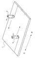
図4には、脆性材料基板17を分断する際の模式図が示されている。なお、図4においては、ホルダーユニット30と脆性材料基板17のみを示している。
FIG. 4 shows a schematic diagram when the
スクライブ装置10においては、スクライビングホイール40は、一定の方向に回転して脆性材料基板17を分断するようになっている。具体的には、脆性材料基板17を分断する際、ホルダー24の傾斜部34a側が常に進行方向となる。図4において、脆性材料基板17を右方向に分断する場合は、ホルダー24の傾斜部34a側が右方向となる。これに続けて、脆性材料基板17を左方向に分断する場合は、ホルダージョイント23の回転軸部23aを介してジョイント部23bが回転し、ホルダー24の傾斜部34a側が左方向となる。
In the
次に、スクライビングホイール40の製造方法の一例について具体的に説明する。
図5(a)には面取部47が形成される前の刃42の拡大側面図及び拡大正面図が示され、図5(b)には面取部47が形成された後の刃42の拡大側面図及び拡大正面図が示されている。
Next, an example of a method for manufacturing the
FIG. 5A shows an enlarged side view and an enlarged front view of the
まず、ダイヤモンド粒子、添加剤、結合材を混合し、ダイヤモンドが熱力学的に安定となる高温及び超高圧下において、これら混合物を焼結させる。これにより焼結ダイヤモンドが製造される。この焼結時において、超高圧発生装置の金型内の圧力は5.0〜8.0GPaの範囲であり、金型内の温度は1500〜1900℃の範囲である。 First, diamond particles, an additive, and a binder are mixed, and the mixture is sintered at a high temperature and ultrahigh pressure at which diamond is thermodynamically stable. As a result, sintered diamond is produced. During this sintering, the pressure in the mold of the ultrahigh pressure generator is in the range of 5.0 to 8.0 GPa, and the temperature in the mold is in the range of 1500 to 1900 ° C.
続いて、製造された焼結ダイヤモンドから所望の半径となる円板が切り取られる。そして、この円板の周縁部において、両面側それぞれを削ることで断面V字状の刃42が形成される。
Subsequently, a disk having a desired radius is cut from the manufactured sintered diamond. A
刃42の稜線部分である刃先43に対し直交するようにして円板状の砥石を当接させることで、刃先43に図5(a)に示すような略U字状の溝46が形成される。一つの溝46を形成するごとに、砥石を退避させる。そして、刃42を所定のピッチに相当する回転角だけ回転させた後、再び砥石を当接させることで、次の溝46が形成される。このようにして、スクライビングホイール40の刃42の先端には、刃先43と溝46とが交互に等ピッチで設けられる。刃先43は、二つの溝46に挟まれるようにして配置されることとなる。
A substantially
次いで、溝46と刃先43との交点に形成される角(エッジ)49にレーザを照射し、この角49を面取りする。これにより、図5(b)に示すように、溝46の周方向に対する端部に面取部47が形成される。
Next, a laser is irradiated to a corner (edge) 49 formed at the intersection of the
面取りは、図5(a)に示される刃先43部分について、周方向の長さに対して20〜40%の範囲となるように行う。すなわち、面取部47が形成された後の刃先43の周方向に対する長さが、面取部47を形成する前の刃先43の周方向に対する長さに対して、60〜80%の範囲となるように面取りする。面取りを、周方向の長さに対して20〜40%の範囲となるよう行った場合、この範囲外である場合と比較して、刃先43の周方向に対する長さが十分に確保される。このため、脆性材料基板17を分断する性能の低下が抑制される。例えば、面取部47形成前の刃先43の周方向の長さは11μmであり、面取部47形成後の刃先の周方向の長さは8μmである。
同様に、溝46の縁48にレーザを照射することにより、面取部48aが形成される。
このようにして、スクライビングホイール40が製造される。
なお、面取部46a、48aは角(エッジ)49や縁48を砥石によって研磨することにより形成することもできる。
The chamfering is performed so that the
Similarly, the
In this way, the
The
次に、スクライビングホイール40により脆性材料基板17を分断した際の、スクライビングの痕(分断痕)について説明する。
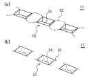
図6(a)には、面取部47の形成されていないスクライビングホイール(図5(a)に示すように、面取部47を形成する前の刃42を有するスクライビングホイール、以下、「比較例としてのスクライビングホイール」と称する)を用いた場合の分断痕の模式図が示され、図6(b)には、本実施形態に係るスクライビングホイール40を用いた場合の分断痕の模式図が示されている。
Next, scribing marks (splitting marks) when the
FIG. 6A shows a scribing wheel in which the chamfered
図6(a)に示すように、比較例としてのスクライビングホイールによる分断痕は、窪み50が分断する線上(スクライブライン上)に複数連なった状態となる。窪み50は、進行方向に対して前後に位置する二つの三角形の面と、進行方向に対して直交する両側に位置する二つの台形の面とで囲まれたような形状であり、これら二つの台形の面が接する稜線51に向けて凹むように傾斜した形態となっている。
As shown to Fig.6 (a), the division | segmentation trace by the scribing wheel as a comparative example will be in the state with which it continued in multiple numbers on the line (on scribe line) which the hollow 50 divides | segments. The
比較例としてのスクライビングホイールにおいては、窪み50の端部から比較的長いクラック52が、分断方向から離れる方向に向けて放射状に生じる。クラック52が長くなると、隣の窪み50から生じるクラック52とつながり易くなり、これにより比較的大きなカレットが生じる等、分断の性能を低下させ得る。放射状に生じるクラック52は、スクライブライン上よりも外側に広がり易く、分断後の脆性材料基板17に影響を与え得る。また、放射状に生じるクラック52は、スクライビングライン自体の幅を増加させる。
In the scribing wheel as a comparative example, relatively long cracks 52 are generated radially from the end of the
図6(b)に示すように、本実施形態に係るスクライビングホイール40による分断痕は、窪み53がスクライブライン上に複数連なった状態となる。窪み53は、進行方向に対して前後に位置する二つの三角形の面と、進行方向に対して直交する両側に位置する二つの台形の面とで囲まれたような形状であり、これら二つの台形の面が接する稜線54に向けて凹むように傾斜した形態となっている。稜線54は、窪み50の稜線51(図6(a))と比較して短く、稜線54に近い頂点に向け、三角形の面の傾斜が緩やかになっている。また、面取部48aに対応して、窪み53の稜線54以外の部分が面取りされた形状となる。
As shown in FIG. 6B, the severance mark by the
本実施形態に係るスクライビングホイール40においては、本構成を有さない場合と比較して、窪み53からのクラック55が長くなり難く、また、放射状になり難い。長いクラック55が形成され難いため、隣の窪み53から生じるクラック55とつながり難くなる。さらに、クラック55は放射状に形成され難く分断方向に形成され易いため、スクライブライン上に収まり易い。
In the
このように、溝46の周方向に対する端部に面取部47が形成されているスクライビングホイール40を用いて脆性材料基板17を分断することにより、分断する性能の低下が抑制される。さらには、分断する性能が急激に変化することが抑制される。
また、縁部48に面取部48aが形成されていることにより、溝46がガラスへ面接触して食い込み難くなるため、さらに窪み53からのクラック55が長くなり難く、また、放射状になり難くなる。
さらに、スクライビングホイール40の刃先43が欠けると、分断する性能が低下する。また、刃先43の欠けが大きくなるほど、分断する性能は急激に変化し易い。これに対して、溝部44に面取部47を形成した場合、本構成を有さない場合と比較して、刃先43が欠け難くなるとともに、刃42の欠けが大きくなることが抑制される。
As described above, by dividing the
Further, since the chamfered
Furthermore, if the
溝46の周方向に対する端部を面取りしたスクライビングホイール40によりスクライブすることで、カレットの増大化が抑制され、さらにはカレット自体の発生が抑制される。
By scribing with the
[第二実施形態]
次に、本発明の第二実施形態について説明する。第一実施形態と同一の部材には同一の符号を付し、重複する説明は省略する。第一実施形態においては、平面状の面取部47を形成しているのに対し、第二実施形態においては、曲面状の面取部60を形成している点で、両者は異なっている。
[Second Embodiment]
Next, a second embodiment of the present invention will be described. The same members as those in the first embodiment are denoted by the same reference numerals, and redundant description is omitted. In the first embodiment, a flat chamfered
図7には、第二実施形態に係るスクライビングホイール40の刃42の拡大側面図及び拡大正面図が示されている。
FIG. 7 shows an enlarged side view and an enlarged front view of the
第二実施形態において溝部44は、刃先43よりも本体部41の中心側(貫通孔45側)に窪んだ溝46を備え、本体部41の周方向に対するこの溝46の両端部に曲面状の面取部60が形成されている。溝46と刃先43とが面取部60を介して連続している場合、溝46と刃先43とが面取部47を介さずに連続している場合と比較して、より滑らかに連続した面が形成される。このため、刃42に角(エッジ)が形成されることがより抑制される。
In the second embodiment, the
上記実施形態においては、本体部41の周方向に対する溝46の両端部に面取部47又は面取部60が形成されている構成について説明したが、これに限らず、面取部47又は面取部60を溝46の片側に形成するようにしてもよい。より具体的には、脆性材料基板17を分断する際に、溝46の両端部のうち先にこの脆性材料基板17と接触する側の端部に面取部47又は面取部60を形成するようにしてもよい。
また、溝46の形状が略U字状である場合を用いて説明したが、これに限らず、V字状、台形状など種々の形状としてもよい。
In the above embodiment, the configuration in which the chamfered
Moreover, although the case where the shape of the groove |
本実施形態においてスクライブ装置10は、スクライビングホイール40を保持するホルダー24をスクライブヘッド21に取り付ける際に、ホルダージョイント23を介して取り付ける構成となっている。しかしながら、スクライブ装置10は、スクライブヘッド21に直接ホルダー24を取り付ける構成であってもよい。
In the present embodiment, the
また、本実施形態においては、スクライブ装置10として、スクライブヘッド21を移動させためのガイド22やブリッジ19が設けられていたり、脆性材料基板17が載置されるテーブル16を回転させる移動台11が備わっていたりするものを示したが、このようなスクライブ装置10に限定されるものではない。例えば、ホルダー24が取り付けられたスクライブヘッド21をユーザーが握れるようにするために、スクライブヘッド21の一部形状が柄の形状をしており、ユーザーがこの柄を持って移動させることで脆性材料基板17の分断を行うような、所謂手動式のスクライブ装置であっても適用可能である。
In the present embodiment, the
10 スクライブ装置
11 移動台
12a,12b 案内レール
13 ボールネジ
14 モータ
15 モータ
16 テーブル
17 脆性材料基板
18 カメラ
19 ブリッジ
20a 支柱
21 スクライブヘッド
22 ガイド
23 ホルダージョイント
23a 回転軸部
23b ジョイント部
24 ホルダー
25a,25b ベアリング
25c スペーサ
26 開口
27 マグネット
28 平行ピン
29a 平坦部
29b 平坦部
30 ホルダーユニット
31 保持溝
32 ピン孔
33 ピン
34 取付部
34a 傾斜部
34b 平坦部
40 スクライビングホイール
41 本体部
42 刃
43 刃先
44 溝部
45 貫通孔
46 溝
47 面取部
48 縁
48a 面取部
49 角
50,53 窪み
51,54 稜線
52,55 クラック
60 面取部
DESCRIPTION OF
Claims (4)
前記溝の周方向に対する端部を面取りする工程と、
を含み、
面取りを、レーザ加工により行うスクライビングホイールの製造方法。 Forming a groove on the periphery of the substrate using a grindstone;
Chamfering the end of the groove with respect to the circumferential direction;
Including
A scribing wheel manufacturing method in which chamfering is performed by laser processing.
をさらに含む請求項1または2に記載のスクライビングホイールの製造方法。 Chamfering an end in a direction perpendicular to the circumferential direction of the groove;
The manufacturing method of the scribing wheel of Claim 1 or 2 which further contains these.
面取りを、二つの前記溝で挟まれる稜線の周方向の長さに対して20〜40%の範囲で行う請求項1〜3いずれかに記載のスクライビングホイールの製造方法。
In the step of forming the groove, a plurality of grooves are formed so as to extend over the entire periphery of the substrate,
The manufacturing method of the scribing wheel in any one of Claims 1-3 which chamfers in 20 to 40% of range with respect to the length of the circumferential direction of the ridgeline pinched by the two said groove | channels.
Priority Applications (1)
| Application Number | Priority Date | Filing Date | Title |
|---|---|---|---|
| JP2013053996A JP6182334B2 (en) | 2013-03-15 | 2013-03-15 | Manufacturing method of scribing wheel |
Applications Claiming Priority (1)
| Application Number | Priority Date | Filing Date | Title |
|---|---|---|---|
| JP2013053996A JP6182334B2 (en) | 2013-03-15 | 2013-03-15 | Manufacturing method of scribing wheel |
Related Child Applications (1)
| Application Number | Title | Priority Date | Filing Date |
|---|---|---|---|
| JP2017051801A Division JP6344582B2 (en) | 2017-03-16 | 2017-03-16 | Scribing wheel, scribing device and dividing method |
Publications (3)
| Publication Number | Publication Date |
|---|---|
| JP2014177085A JP2014177085A (en) | 2014-09-25 |
| JP2014177085A5 JP2014177085A5 (en) | 2016-04-28 |
| JP6182334B2 true JP6182334B2 (en) | 2017-08-16 |
Family
ID=51697515
Family Applications (1)
| Application Number | Title | Priority Date | Filing Date |
|---|---|---|---|
| JP2013053996A Expired - Fee Related JP6182334B2 (en) | 2013-03-15 | 2013-03-15 | Manufacturing method of scribing wheel |
Country Status (1)
| Country | Link |
|---|---|
| JP (1) | JP6182334B2 (en) |
Families Citing this family (3)
| Publication number | Priority date | Publication date | Assignee | Title |
|---|---|---|---|---|
| JP6910643B2 (en) * | 2017-07-26 | 2021-07-28 | 三星ダイヤモンド工業株式会社 | Scribing wheel |
| JP7008959B2 (en) * | 2017-08-31 | 2022-01-25 | 三星ダイヤモンド工業株式会社 | Scribing wheel |
| JP2022038435A (en) * | 2020-08-26 | 2022-03-10 | ファインテック株式会社 | Scribing wheel for brittle material substrate and method for producing the same |
Family Cites Families (6)
| Publication number | Priority date | Publication date | Assignee | Title |
|---|---|---|---|---|
| JP4698651B2 (en) * | 2001-03-16 | 2011-06-08 | 三星ダイヤモンド工業株式会社 | Cutter wheel and scribing device using the cutter wheel |
| JP2008023657A (en) * | 2006-07-21 | 2008-02-07 | Tungaloy Corp | Lathe turning tool |
| JP2009234874A (en) * | 2008-03-28 | 2009-10-15 | Shiba Giken:Kk | Cutter wheel and method for manufacturing the same |
| JP5365300B2 (en) * | 2009-03-27 | 2013-12-11 | 三菱マテリアル株式会社 | Cutting tools |
| JP5408450B2 (en) * | 2010-11-29 | 2014-02-05 | 三星ダイヤモンド工業株式会社 | Scribing wheel |
| CN108481580B (en) * | 2012-07-27 | 2020-10-23 | 二和钻石工业股份有限公司 | Scribing wheel with precise structure groove |
-
2013
- 2013-03-15 JP JP2013053996A patent/JP6182334B2/en not_active Expired - Fee Related
Also Published As
| Publication number | Publication date |
|---|---|
| JP2014177085A (en) | 2014-09-25 |
Similar Documents
| Publication | Publication Date | Title |
|---|---|---|
| JP2015048260A (en) | Scribing wheel, holder unit, and scribing device | |
| JP6357746B2 (en) | Scribing wheel, holder unit, scribing device, scribing wheel manufacturing method and scribing method | |
| JP5479424B2 (en) | Scribing wheel for brittle material, scribing device and scribing tool for brittle material substrate using the same | |
| WO2010063161A1 (en) | Cutter wheel for cutting fragile material and manufacturing method thereof | |
| JP2008037732A (en) | Cutter wheel for cutting glass | |
| JP2007152936A (en) | Wheel cutter for brittle material | |
| TW201313637A (en) | Scribing wheel | |
| JP2014188729A (en) | Scribing wheel, scribing device, and method of manufacturing scribing wheel | |
| JP6182334B2 (en) | Manufacturing method of scribing wheel | |
| TWI490178B (en) | Engraving wheel, scribing device and marking wheel manufacturing method | |
| JP5365602B2 (en) | Scribing wheel and manufacturing method thereof | |
| JP2014189415A (en) | Scribing wheel, holder unit, scribing device, scribing method, and production method of scribing wheel | |
| JP6344582B2 (en) | Scribing wheel, scribing device and dividing method | |
| JP6422009B2 (en) | Scribing wheel and manufacturing method thereof | |
| JP5925286B2 (en) | Scribing wheel, scribing device, and scribing wheel manufacturing method | |
| JP6458372B2 (en) | Multipoint diamond tool and method of manufacturing multipoint diamond tool | |
| JP5983364B2 (en) | End mill | |
| JP2015209350A (en) | Method for manufacturing scribing tool, scribing tool, scribing apparatus and scribing method | |
| TWI603929B (en) | Scribing wheel with pin, holding unit and scoring device | |
| JP2019043124A (en) | Scribing wheel, method for producing the same, scribe method, and holder unit | |
| JP2011093191A (en) | Scribing wheel | |
| JP2011093190A (en) | Scribing wheel | |
| JP7008961B2 (en) | Scribing wheel, holder unit and scribe method | |
| JP2012115991A (en) | Scribing wheel | |
| JP2006104029A (en) | Cutter wheel for cutting glass |
Legal Events
| Date | Code | Title | Description |
|---|---|---|---|
| A521 | Request for written amendment filed |
Free format text: JAPANESE INTERMEDIATE CODE: A523 Effective date: 20160314 |
|
| A621 | Written request for application examination |
Free format text: JAPANESE INTERMEDIATE CODE: A621 Effective date: 20160314 |
|
| A977 | Report on retrieval |
Free format text: JAPANESE INTERMEDIATE CODE: A971007 Effective date: 20170117 |
|
| A131 | Notification of reasons for refusal |
Free format text: JAPANESE INTERMEDIATE CODE: A131 Effective date: 20170119 |
|
| A521 | Request for written amendment filed |
Free format text: JAPANESE INTERMEDIATE CODE: A523 Effective date: 20170316 |
|
| TRDD | Decision of grant or rejection written | ||
| A01 | Written decision to grant a patent or to grant a registration (utility model) |
Free format text: JAPANESE INTERMEDIATE CODE: A01 Effective date: 20170630 |
|
| A61 | First payment of annual fees (during grant procedure) |
Free format text: JAPANESE INTERMEDIATE CODE: A61 Effective date: 20170724 |
|
| R150 | Certificate of patent or registration of utility model |
Ref document number: 6182334 Country of ref document: JP Free format text: JAPANESE INTERMEDIATE CODE: R150 |
|
| LAPS | Cancellation because of no payment of annual fees |