JP2007152936A - Wheel cutter for brittle material - Google Patents
Wheel cutter for brittle material Download PDFInfo
- Publication number
- JP2007152936A JP2007152936A JP2006230886A JP2006230886A JP2007152936A JP 2007152936 A JP2007152936 A JP 2007152936A JP 2006230886 A JP2006230886 A JP 2006230886A JP 2006230886 A JP2006230886 A JP 2006230886A JP 2007152936 A JP2007152936 A JP 2007152936A
- Authority
- JP
- Japan
- Prior art keywords
- wheel cutter
- blade portion
- laser processing
- wheel
- groove
- Prior art date
- Legal status (The legal status is an assumption and is not a legal conclusion. Google has not performed a legal analysis and makes no representation as to the accuracy of the status listed.)
- Pending
Links
Images


Classifications
-
- C—CHEMISTRY; METALLURGY
- C03—GLASS; MINERAL OR SLAG WOOL
- C03B—MANUFACTURE, SHAPING, OR SUPPLEMENTARY PROCESSES
- C03B33/00—Severing cooled glass
- C03B33/10—Glass-cutting tools, e.g. scoring tools
- C03B33/105—Details of cutting or scoring means, e.g. tips
- C03B33/107—Wheel design, e.g. materials, construction, shape
Abstract
Description
この発明は、ガラス板その他の脆性材料を切断するため、ダイヤモンド焼結体や超硬合
金等が用いられたホイールカッターに関するものである。
The present invention relates to a wheel cutter in which a diamond sintered body, a cemented carbide or the like is used to cut a glass plate or other brittle material.
従来より、液晶体基板ガラス、セラミック基板、硬質ガラス板などの脆性材料(ガラス
板等)上に転動させることによりスクライブライン(リブマーク)を刻んでこれを切断(
カッティング)するため、ダイヤモンド焼結体や超硬合金等が用いられたホイールカッタ
ーが使用されている(例えば、特許文献1参照)。
Conventionally, a scribe line (rib mark) is engraved by rolling on a brittle material (glass plate, etc.) such as a liquid crystal substrate glass, a ceramic substrate, or a hard glass plate (
In order to perform cutting, a wheel cutter using a diamond sintered body, a cemented carbide or the like is used (for example, see Patent Document 1).
図5に示すように、このホイールカッターは、リブマーク形成用の刃部21と回転支持用の摺動部22とを有する回転体部23と、その両側の支持体部24とを具備し、前記回転体部23における摺動部22とその両側の支持体部24とが面接触して回転するようにしている。
As shown in FIG. 5, the wheel cutter includes a rotating
このホイールカッターでは摺動部22とその両側の支持体部24との摺動当たり面の回転摩擦を大きく設定できるため、脆性材料上に回転体部23を転動させる際に刃圧を強くすることができ、脆性材料に対して刃部21を押し付けスリップし難くして回転させスクライブラインを深く入れることができる。
In this wheel cutter, since the rotational friction of the sliding contact surface between the sliding
ところで昨今、液晶商品はテレビ、パソコン、携帯電話、デジタルカメラその他種々の
機器に利用され、その高品質への要求がより高まってきており、リブマーク形成時に切り
粉や切込みラインの角欠けが極力発生しないことが求められる。
そこでこの発明は、リブマーク形成時に切り粉や切込みラインの角欠けが発生し難い脆
性材料用のホイールカッターを提供しようとするものである。
Accordingly, the present invention is intended to provide a wheel cutter for a brittle material in which chips and cuts of cut lines are not easily generated when a rib mark is formed.
前記課題を解決するためこの発明では次のような技術的手段を講じている。
(1)この発明の脆性材料用のホイールカッターは、リブマークを形成すべき刃部を有する
回転ホイール体を具備し、前記刃部にはその斜面に沿った複数の長溝がレーザー加工によ
り形成されると共に、前記長溝の角部にアールを付けるように研磨されていることを特徴
とする。
In order to solve the above problems, the present invention takes the following technical means.
(1) A wheel cutter for a brittle material according to the present invention includes a rotating wheel body having a blade portion on which a rib mark is to be formed, and a plurality of long grooves along the slope are formed on the blade portion by laser processing. And it is grind | polished so that a corner | angular part of the said long groove may be rounded.
この脆性材料用のホイールカッターは、刃部の斜面に沿ってレーザー加工により形成さ
れた複数の長溝の角部(エッジ)にアールを付ける(エッジを落として丸くする)ように
研磨されているので、刃部を滑らかで精度がある円周研磨面とすることができ、リブマー
ク形成のための切込み時に溝の角部からガラス面に対する加圧抵抗を弱くすることができる。
Since this wheel cutter for brittle materials is polished so that the corners (edges) of a plurality of long grooves formed by laser processing along the slope of the blade part are rounded (the edge is dropped and rounded). The blade portion can be a smooth and accurate circumferential polished surface, and the pressure resistance from the corner portion of the groove to the glass surface can be reduced at the time of cutting for forming the rib mark.
また、刃部の斜面ではなく先端にレーザー加工で溝を形成しこの際にできた焼けカスの
層を研磨して除去しようとした場合には溝自体も一緒に摩滅して殆どなくなってしまいがちであるが、この発明では刃部にはその斜面に沿った複数の長溝がレーザー加工により形成されているので、このように斜面に沿った長溝を形成したことによりレーザー加工時にできた焼けカスの層を研磨して除去しても斜面に沿った長溝は摩滅することなく残存し易いこととなる。
In addition, if a groove is formed by laser processing at the tip of the blade instead of the slope, and the burnt residue layer formed at this time is polished and removed, the groove itself tends to be worn away and almost lost. However, in the present invention, a plurality of long grooves along the inclined surface are formed by laser processing in the blade portion. Thus, by forming the long grooves along the inclined surface in this way, the burnt residue generated at the time of laser processing is formed. Even if the layer is polished and removed, the long grooves along the inclined surface are likely to remain without being worn out.
さらに、長溝の角部へのアール付けの研磨加工時に同時に溝の深さを調整することによ
ってガラスの厚さに対応することが可能であり、これによって超精密カットを得ることが
できる。
Furthermore, it is possible to cope with the thickness of the glass by adjusting the depth of the groove at the same time as the rounding process to the corner of the long groove, thereby obtaining an ultra-precise cut.
ここで、このホイールカッターは回転ホイール体の転動にともない、前記溝(長溝)が
間欠的に(カタカタと)脆性材料に当接していきリブマークが次々と形成されていく。な
お前記長溝のレーザー加工は、公知のレーザー光発生装置(ヤグレーザー等)により行う
ことができる。また前記回転ホイール体の外形は、ディスク状としたりそろ盤玉状とした
りすることができる。
Here, in the wheel cutter, as the rotating wheel body rolls, the groove (long groove) abuts against the brittle material intermittently (in a rattling manner), and rib marks are formed one after another. The laser processing of the long groove can be performed by a known laser light generator (eg, a yag laser). Further, the outer shape of the rotating wheel body can be a disk shape or a bead shape.
(2) 前記長溝は刃部の片側の斜面に形成されたこととしてもよい。 (2) The long groove may be formed on a slope on one side of the blade portion.
このように構成すると、長溝は刃部の片側の斜面だけに存するので、長溝を刃部の両側
の斜面に形成した場合と比べてリブマーク形成時に切り粉がさらに発生し難いものとなる。
If comprised in this way, since a long groove exists only in the slope of one side of a blade part, compared with the case where a long groove is formed in the slope of the both sides of a blade part, it will become a thing which does not generate | occur | produce chips more easily at the time of rib mark formation.
(3) 前記回転ホイール体は刃部と共に回転支持部を有し、この回転支持部と両側の回転
受け部とは略点接触して回転するようにしたこととしてもよい。
(3) The rotating wheel body may have a rotation support portion together with the blade portion, and the rotation support portion and the rotation receiving portions on both sides may rotate substantially in point contact.
このように構成すると、非常な低摩擦で回転させることができるので、軽回転でリブマ
ークを円滑に形成していくことができるという利点がある。
This configuration has an advantage that the rib mark can be smoothly formed with a light rotation since it can be rotated with very low friction.
(4) この脆性材料用のホイールカッターの製造方法は、リブマークを形成すべき刃部を
有する回転ホイール体を具備するホイールカッターの製造方法であって、前記刃部の斜面
に沿った少し深めの複数の長溝をレーザー加工により形成するレーザー加工工程と、前記
長溝の角部にアールを付ける研磨工程とを有することを特徴とする。
(4) The manufacturing method of the wheel cutter for the brittle material is a manufacturing method of a wheel cutter including a rotating wheel body having a blade portion on which a rib mark is to be formed, and is slightly deeper along the slope of the blade portion. It has a laser processing process of forming a plurality of long grooves by laser processing, and a polishing process for rounding corners of the long grooves.
この脆性材料用のホイールカッターの製造方法は、刃部の斜面に沿ってレーザー加工に
より形成された複数の長溝の角部(エッジ)にアールを付ける(エッジを落として丸くす
る)ように研磨されているので、刃部を滑らかで精度がある円周研磨面とすることができ
、リブマーク形成のための切込み時に溝の角部からガラス面に対する加圧抵抗を弱くする
ことができる。
This method of manufacturing a wheel cutter for brittle materials is polished so that the corners (edges) of a plurality of long grooves formed by laser processing along the slope of the blade part are rounded (the edge is dropped and rounded). Therefore, the blade portion can be a smooth and accurate circumferential polished surface, and the pressure resistance from the corner portion of the groove to the glass surface can be weakened at the time of cutting for forming the rib mark.
また、刃部の斜面ではなく先端にレーザー加工で溝を形成しこの際にできた焼けカスの
層を研磨して除去しようとした場合には溝自体も一緒に摩滅して殆どなくなってしまいがちであるが、この発明では刃部にはその斜面に沿った少し深めの複数の長溝がレーザー加工により形成されているので、このように斜面に沿った長溝を形成したことによりレーザー加工時にできた焼けカスの層を研磨して除去しても斜面に沿った長溝は摩滅することなく残存し易いこととなる。
In addition, if a groove is formed by laser processing at the tip of the blade instead of the slope, and the burnt residue layer formed at this time is polished and removed, the groove itself tends to be worn away and almost lost. However, in the present invention, since the blade portion is formed by laser processing with a plurality of long grooves slightly deeper along the slope, the long groove along the slope was formed at the time of laser processing. Even if the burnt residue layer is polished and removed, the long groove along the slope is likely to remain without being worn away.
この発明は上述のような構成であり、次の効果を有する。 The present invention is configured as described above and has the following effects.
リブマーク形成のための切込み時に溝の角部からガラス面に対する加圧抵抗を弱くすることができるので、リブマーク形成時に切り粉や切込みラインの角欠けが発生し難い脆性材料用のホイールカッターを提供することができる。 Provided is a wheel cutter for a brittle material in which chipping and chipping of a cutting line are less likely to occur at the time of rib mark formation because the pressure resistance against the glass surface from the corner of the groove can be weakened at the time of cutting for rib mark formation. be able to.
以下、この発明の実施の形態を、図面を参照して説明する。 Embodiments of the present invention will be described below with reference to the drawings.
この脆性材料用のホイールカッターは、液晶体基板ガラス(テレビ、パソコン、携帯電
話等)、セラミック基板、硬質ガラス板などの脆性材料上に転動させることによりリブマ
ーク(脆性材料の厚みの深さ方向に亀裂を伸長させる)を刻んでこれを切断するものであ
る。特に、携帯電話の液晶表示面に使用される薄肉のガラス基板の切断に好適に使用する
ことができ、近時の厚み0.3mm程度の液晶ガラス基板にも対応することができるもの
である。
This wheel cutter for brittle materials is rolled on brittle materials such as liquid crystal substrate glass (TVs, personal computers, mobile phones, etc.), ceramic substrates, hard glass plates, etc., and rib marks (in the depth direction of the brittle material thickness) This is to cut the cracks. In particular, it can be suitably used for cutting a thin glass substrate used for a liquid crystal display surface of a mobile phone, and can be applied to a liquid crystal glass substrate having a thickness of about 0.3 mm.
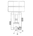
図1乃至図4に示すように、この実施形態のホイールカッターは、リブマークを形成す
べき断面略V字状の刃を備えるディスク状の刃部1を有する回転ホイール体2を具備する。前記断面略V字状の角度は、110〜150度(好ましくは120〜125度)に設定した。前記回転ホイール体2はディスク状の刃部1(ダイヤモンド粉末焼結体製)と共にピン状の回転支持部3(超硬合金製)を有し、この回転支持部3と両側のすり鉢状(内面角度θ1は90度)の回転受け部4(超硬合金製)とが点接触して超低荷重で回転するようにしており、殆ど負荷がない状態で回転する。
As shown in FIGS. 1 to 4, the wheel cutter of this embodiment includes a rotating
具体的には前記回転ホイール体2は、先端に超精密R加工を施したピン状の回転支持部
3(天芯のR0.2、外面角度θ2は80度)が、ディスク状の刃部1に精密に芯出しし
て固着・一体化されている。すなわち、ディスク状の刃部1の片側の側面には超硬合金層
21が形成され(超硬合金とダイヤモンド粉末焼結体との合体一体化)、この層にロー付け
部22によりピン状の回転支持部3と固着・一体化されている。前記刃部1の外形はディスク状としたが、刃部1と回転支持部3とが連続一体的なそろ盤玉状とすることもできる。
前記ダイヤモンド粉末焼結体の部分は超硬合金等で形成してもよい。
Specifically, the
21 is formed (integrated integration of the cemented carbide and the diamond powder sintered body), and this layer is fixed and integrated with the pin-shaped
The diamond powder sintered body may be formed of a cemented carbide or the like.
前記一対の回転受け部4は、ステンレス板製のホルダー5に支持固定されている。ステ
ンレスではなく、超硬合金製(タングステンカーバイト)とすることもできる。前記ホル
ダー5は、リング(座金)6を介して回動自在のベアリング体7に接続している。8は全
体の締付け用ビス、9は遊び調整用ビス、10は精度位置決定用ビスである。
The pair of
前記刃部1にはその片側の斜面に沿った少し深めの複数の長溝11(深さ30〜70μm
)がレーザー加工により略V字状の刃部1の頂部に向けて放射状に形成されると共に、前
記長溝(深溝)11の角部E(溝角、エッジ)にアールを付ける(エッジを落として丸くす
る)ように研磨されており、具体的には前記長溝11はレーザー加工時に付着した焼けカスの層が精密研磨され刃部1の刃付け加工がされている。焼けカス層の研磨後の長溝11の深さは、10〜50μm程度としている。ここで前記長溝11のレーザー加工は、レーザー光発生装置(ヤグレーザー等)により公知の方法で行うことができる。
The
) Is formed radially by laser processing toward the top of the substantially V-
ここで、回転ホイール体2の直径d1は2.0〜3.5mmに、V字状の刃部1の幅d
2は0.325mmに、長溝11の長さd3は0.3mmに、回転ホイール体2の外周の長溝11の本数は120本、長溝11の幅d4は0.03〜0.1mmに、長溝11間のピッチd5は0.02〜0.05mm、ピン状の回転支持部3の直径d6は1.0〜1.3mmとしている。
Here, the diameter d1 of the rotating
2 is 0.325 mm, the length d3 of the
上記のようにこの脆性材料用のホイールカッターの製造方法は、刃部1の斜面に沿った
少し深めの複数の長溝11をレーザー加工により形成するレーザー加工工程と、前記長溝11の角部にアールを付けるように研磨し、レーザー加工時に付着した焼けカスの層を前記長溝11から研磨する研磨工程(刃付けする)とを有する。
As described above, the manufacturing method of the wheel cutter for the brittle material includes a laser processing step of forming a plurality of
そして、カット時にはこのホイールカッターは回転ホイール体2の転動にともない、前
記刃部1の溝(長溝11)が間欠的にカタカタと脆性材料に当接していきリブマークが次々
と形成されていく。このホイールカッターは、押圧切通し分断装置を必要としないノーブ
レーク方式でカットすることが出来る。
At the time of cutting, as the
次に、この実施形態の脆性材料用のホイールカッターの使用状態を説明する。 Next, the use state of the wheel cutter for a brittle material of this embodiment will be described.
この脆性材料用のホイールカッターは、刃部1の斜面に沿ってレーザー加工により形成
された少し深めの複数の長溝11の角部Eにアールを付けるように研磨されているので、刃部1を滑らかで精度がある円周研磨面とすることができ、リブマーク形成のための切込み時に溝の角部Eからガラス面に対する加圧抵抗を弱くすることができ、リブマーク形成時に切り粉や切込みラインの角欠けが非常に発生し難いという利点がある。このように切込み時の切り粉の発生とガラス面の角欠け発生を解消することができ、溝角の円周に沿った精度よい研磨ができるので、不良品を大幅に改善することができる。
Since the wheel cutter for the brittle material is polished so that the corners E of the plurality of
また、前記刃部1は焼けカスの層が研磨された綺麗な溝によりガラス基板(脆性材料)
に滑らかに切込み抵抗をかけていくことが出来る。形成されたリブマークは、浅い箇所が
あったり深い箇所があったりする不均一なものではなく、ほぼ同じ深さに均一に形成され
ていた。さらに、カットされたガラス断面も均一性に優れた綺麗なものであった。
Further, the
Can be applied smoothly. The formed rib marks were not uniform with a shallow portion or a deep portion, and were uniformly formed at substantially the same depth. Furthermore, the cut glass section was also beautiful with excellent uniformity.
さらに、先端に超精密R加工を施したピン状の回転支持部3とその両側のすり鉢状の回
転受け部4とが点接触して超低荷重で回転することにより、遊び(横振れ)0の超精密軽
回転を持続することができ、リブマーク形成時に所謂カジリ現象(回転が止まった凍結状
態のまま引きずられていくこと)が発生することはなく正常回転で非常に長い走行寿命を
得ることができた。すなわち、携帯電話用の厚み0.5mmのガラス基板について、50
万〜70万m以上を正常回転でカットすることができ超長寿命である。よって、生産工程
でのカット不良の発生を大幅に改善することが期待出来る。
Further, the pin-shaped
10,000 to 700,000 m or more can be cut with normal rotation and has a very long life. Therefore, it can be expected to greatly improve the occurrence of cut defects in the production process.
また、刃部1の斜面ではなく先端のみにレーザー加工で溝を形成(図示せず)しこの際
にできた焼けカスの層を研磨して除去しようとした場合には溝自体も一緒に摩滅して殆どなくなってしまいがちであるが、この実施形態では刃部1にはその斜面に沿った少し深めの複数の長溝11がレーザー加工により形成されているので、このように斜面に沿った長溝11を形成したことによりレーザー加工時にできた焼けカスの層を研磨して除去しても斜面に沿った長溝11は摩滅することなく残存し易く、また刃付けの超精密加工がし易い。更に、レーザー加工工程で先ず斜面に沿った「長」溝を形成しておくことにより、次工程の超精密研磨工程で刃付けがし易く精度が非常に出し易いという利点がある。
Further, when a groove is formed by laser processing (not shown) only at the tip, not the slope of the
そして、前記長溝11は刃部1の片側の斜面に形成されたこととしており、長溝11は刃部1の片側の斜面だけに存するので、長溝11を刃部1の両側の斜面に形成した場合と比べてリブマーク形成時に切り粉がさらに発生し難い(さらにほぼ半減する)ものとなっているという利点がある。
The
また、前記回転ホイール体2は刃部1と共に回転支持部3を有し、この回転支持部3と
両側の回転受け部4とは点接触して回転するようにしており、カット時には非常低摩擦
で回転させることができるので、軽回転でリブマークを円滑に形成していくことができ、
厚み0.3mm等の非常に薄いガラス基板にも対応することができるという利点がある。
Further, the
There is an advantage that it can be applied to a very thin glass substrate having a thickness of 0.3 mm or the like.
(従来のホイールカッターとこの実施例のホイールカッターの構成等の相違点)
次に、携帯電話等に使用される薄板小型基板等の切断に関し、従来(他社製)のホイールカッターに対する上記実施例のホイールカッターの優位性を説明する。
1.従来のホイールカッターの基本的構成と切断メカニズム
従来のホイールカッターは、支持ピンに回転ホイールを回転自在に取り付けて成るものであり、前記回転ホイールは刃立て仕上げ後、刃先に溝切り工程を経て完成させている。
(Differences between the configuration of the conventional wheel cutter and the wheel cutter of this embodiment)
Next, the superiority of the wheel cutter of the above-described embodiment over the conventional wheel cutter (manufactured by another company) will be described with respect to the cutting of a thin small substrate used for a mobile phone or the like.
1. Basic structure and cutting mechanism of a conventional wheel cutter A conventional wheel cutter consists of a rotating pin attached to a support pin so that it can rotate freely. I am letting.
ここで、このホイールカッターでは、薄板小型基板の面に溝角の鋭角部分を押し付け(加圧し)ながら回転させて、加圧衝撃によりリブマークを深く(薄板小型基板の下面近くまで)入れ、薄板小型基板等を分断する。 Here, with this wheel cutter, the sharp part of the groove angle is pressed (pressurized) against the surface of the thin small board and rotated, and the rib mark is inserted deeply (to the lower surface of the thin small board) by the pressure impact, and the thin board is compact. Divide the substrate.
しかしながら、従来のホイールカッターで、携帯電話等に使用される薄板小型基板を分断した場合、加圧衝撃によるショックの過大性から、リブマーク形成時に切り粉や切込みラインの角欠けが非常に発生し、不良品が多発する。つまり、従来のホイールカッターは、携帯電話等に使用される薄板小型基板の分断には全く向いていない。
2.この発明の実施例のホイールカッターの基本的構成と切断メカニズム
この発明の実施例のホイールカッターは、上記従来のホイールカッターの欠点を解消するためのものであり、その特徴は以下の通りである。
However, when a thin wheeled small substrate used for a mobile phone or the like is divided with a conventional wheel cutter, due to excessive shock due to pressure shock, chipping and chipping of corners of the cutting line are very generated at the time of rib mark formation, Many defective products occur. That is, the conventional wheel cutter is not at all suitable for dividing a thin small board used for a mobile phone or the like.
2. Basic configuration and cutting mechanism of wheel cutter of embodiment of the present invention The wheel cutter of the embodiment of the present invention is for eliminating the above-mentioned disadvantages of the conventional wheel cutter, and its features are as follows.
(特徴1)
刃部1は、リブマークを形成すべき断面V字状の刃(V字状の角度は110〜150°、好ましくは120〜125°)を備えるディスク状のものであり、その片側の斜面に沿った少し深めの複数の長溝11(深さ30〜70μm)がレーザー加工により略V字状の刃部1の頂部に向けて放射状に形成されている。
(Feature 1)
The
(特徴2:最大の特徴部分)
特に、前記長溝(深溝)11の角部E(溝角、エッジ)にはアールを付ける(エッジを落として丸くする)ように研磨され、具体的には長溝11はレーザー加工時に付着した焼けカスの層が精密研磨され刃部1の刃付け加工がされている。
(Feature 2: Maximum feature part)
In particular, the corner E (groove angle, edge) of the long groove (deep groove) 11 is polished so as to be rounded (the edge is dropped and rounded). Specifically, the
ここで、上記特徴1及びこの特徴2の加工法により、焼けカスの層の研磨後の長溝11の深さは10〜50μ程度という肉眼では確認不可能な微細溝が形成されている。
Here, by the processing method of the
この発明の実施例のホイールカッターによると、カット時には回転ホイール体2の転動に伴い、刃部1の長溝11が間欠的にカタカタと脆性材料に当接していきリブマークが次々と形成されていく。つまり、このホイールカッターは、従来のもののように、加圧衝撃によりリブマークを深く(薄板小型基板の下面近くまで)入れて薄板小型基板等を分断するものではなく、ほぼノーブレーク方式で薄板小型基板等をカットすることができる。
According to the wheel cutter of the embodiment of the present invention, as the
したがって、リブマーク形成時に切り粉や切込みラインの角欠けが非常にし難いことになり、その結果、不良品がほとんど無くなる。 Therefore, chipping of chips and cut lines at the time of rib mark formation is very difficult, and as a result, there are almost no defective products.
3.まとめ
以上のことから、携帯電話等に使用される薄板小型基板等の切断に関し、従来(他社製)のホイールカッターよりもこの発明のホイールカッターが如何に優れているかが明らかである。
3. Summary From the above, it is clear how the wheel cutter of the present invention is superior to the conventional (manufactured by other company) wheel cutters for cutting thin plate small substrates used in mobile phones and the like.
リブマーク形成時に切り粉や切込みラインの角欠けが発生し難いことによって、種々の
脆性材料用のホイールカッターの用途に適用することができる。
It is possible to apply to the use of wheel cutters for various brittle materials because it is difficult for the chip and the chipping of the cutting line to occur when the rib mark is formed.
1 刃部
2 回転ホイール体
3 回転支持部
4 回転受け部
11 長溝
DESCRIPTION OF
11 Long groove
Claims (4)
A method of manufacturing a wheel cutter comprising a rotating wheel body (2) having a blade portion (1) on which a rib mark is to be formed, wherein a plurality of long grooves (11) slightly deeper along the slope of the blade portion (1) A method of manufacturing a wheel cutter for a brittle material, comprising: a laser processing step of forming a circle by laser processing; and a polishing step of rounding the corners of the long groove (11).
Priority Applications (1)
| Application Number | Priority Date | Filing Date | Title |
|---|---|---|---|
| JP2006230886A JP2007152936A (en) | 2005-11-09 | 2006-08-28 | Wheel cutter for brittle material |
Applications Claiming Priority (2)
| Application Number | Priority Date | Filing Date | Title |
|---|---|---|---|
| JP2005324457 | 2005-11-09 | ||
| JP2006230886A JP2007152936A (en) | 2005-11-09 | 2006-08-28 | Wheel cutter for brittle material |
Publications (2)
| Publication Number | Publication Date |
|---|---|
| JP2007152936A true JP2007152936A (en) | 2007-06-21 |
| JP2007152936A5 JP2007152936A5 (en) | 2009-08-06 |
Family
ID=38237869
Family Applications (1)
| Application Number | Title | Priority Date | Filing Date |
|---|---|---|---|
| JP2006230886A Pending JP2007152936A (en) | 2005-11-09 | 2006-08-28 | Wheel cutter for brittle material |
Country Status (1)
| Country | Link |
|---|---|
| JP (1) | JP2007152936A (en) |
Cited By (14)
| Publication number | Priority date | Publication date | Assignee | Title |
|---|---|---|---|---|
| WO2008087612A1 (en) * | 2007-01-19 | 2008-07-24 | Dutch Diamond Technologies B.V. | Cutting disk for forming a scribed line |
| WO2009036743A1 (en) * | 2007-09-22 | 2009-03-26 | Bohle Ag | Method for the production of small cutting wheels |
| CN102049813A (en) * | 2009-10-29 | 2011-05-11 | 三星钻石工业股份有限公司 | Scribing wheel and method for manufacturing the same |
| JP2011093186A (en) * | 2009-10-29 | 2011-05-12 | Mitsuboshi Diamond Industrial Co Ltd | Tip holder unit |
| JP2011104852A (en) * | 2009-11-17 | 2011-06-02 | Mitsuboshi Diamond Industrial Co Ltd | Scribing wheel |
| WO2012000986A1 (en) * | 2010-06-28 | 2012-01-05 | Bohle Ag | Cutting tool, in particular cutting wheels, and method for producing the same using an inclined laser beam |
| JP2012027272A (en) * | 2010-07-23 | 2012-02-09 | Asahi Glass Co Ltd | Manufacturing method of display panel, and display panel |
| CN102416671A (en) * | 2010-09-28 | 2012-04-18 | 三星钻石工业股份有限公司 | Scribing method and scribing wheel |
| JP2013028181A (en) * | 2012-10-26 | 2013-02-07 | Mitsuboshi Diamond Industrial Co Ltd | Tip holder unit, and holder |
| CN103085106A (en) * | 2013-02-01 | 2013-05-08 | 四川虹视显示技术有限公司 | Organic light emitting diode (OLED) substrate cutting system |
| JP2013100214A (en) * | 2011-10-13 | 2013-05-23 | Mitsuboshi Diamond Industrial Co Ltd | Holder, holder unit, and scribing device |
| JP2014008710A (en) * | 2012-06-29 | 2014-01-20 | Mitsuboshi Diamond Industrial Co Ltd | Tip holder |
| CN105828965A (en) * | 2013-12-18 | 2016-08-03 | Posco公司 | Side trimming device of steel plate and method therefor |
| JP2016141027A (en) * | 2015-02-02 | 2016-08-08 | 三星ダイヤモンド工業株式会社 | Holder, holder unit and scribe device |
Citations (9)
| Publication number | Priority date | Publication date | Assignee | Title |
|---|---|---|---|---|
| JPH09188534A (en) * | 1995-11-06 | 1997-07-22 | Mitsuboshi Daiyamondo Kogyo Kk | Glass cutter wheel |
| JP2001246616A (en) * | 2000-03-06 | 2001-09-11 | Hitachi Ltd | Roller cutter |
| JP2001300855A (en) * | 2000-04-19 | 2001-10-30 | Sankyo Diamond Industrial Co Ltd | Diamond saw blade |
| JP2002121040A (en) * | 2000-08-11 | 2002-04-23 | Mitsuboshi Diamond Industrial Co Ltd | Cutter wheel for brittle material substrate and scriber having the same |
| JP2002127021A (en) * | 2000-10-19 | 2002-05-08 | Noritake Diamond Ind Co Ltd | Rotary disc cutter |
| JP2004292278A (en) * | 2003-03-28 | 2004-10-21 | Kawaguchiko Seimitsu Co Ltd | Glass cutter wheel, method of manufacturing the same, automatic glass scriber provided with the same, glass cutter, glass cut by using the same and electronic instrument device employing the glass |
| JP2006076873A (en) * | 2004-09-07 | 2006-03-23 | Shizen Gijutsu Kenkyusho | Wheel for cutting glass and its manufacturing method |
| WO2006082899A1 (en) * | 2005-02-02 | 2006-08-10 | Mitsuboshi Diamond Industrial Co., Ltd. | Method of working sintered diamond, cutter wheel for substrate and method of working the same |
| JP2007031200A (en) * | 2005-07-27 | 2007-02-08 | Allied Material Corp | Cutter wheel |
-
2006
- 2006-08-28 JP JP2006230886A patent/JP2007152936A/en active Pending
Patent Citations (9)
| Publication number | Priority date | Publication date | Assignee | Title |
|---|---|---|---|---|
| JPH09188534A (en) * | 1995-11-06 | 1997-07-22 | Mitsuboshi Daiyamondo Kogyo Kk | Glass cutter wheel |
| JP2001246616A (en) * | 2000-03-06 | 2001-09-11 | Hitachi Ltd | Roller cutter |
| JP2001300855A (en) * | 2000-04-19 | 2001-10-30 | Sankyo Diamond Industrial Co Ltd | Diamond saw blade |
| JP2002121040A (en) * | 2000-08-11 | 2002-04-23 | Mitsuboshi Diamond Industrial Co Ltd | Cutter wheel for brittle material substrate and scriber having the same |
| JP2002127021A (en) * | 2000-10-19 | 2002-05-08 | Noritake Diamond Ind Co Ltd | Rotary disc cutter |
| JP2004292278A (en) * | 2003-03-28 | 2004-10-21 | Kawaguchiko Seimitsu Co Ltd | Glass cutter wheel, method of manufacturing the same, automatic glass scriber provided with the same, glass cutter, glass cut by using the same and electronic instrument device employing the glass |
| JP2006076873A (en) * | 2004-09-07 | 2006-03-23 | Shizen Gijutsu Kenkyusho | Wheel for cutting glass and its manufacturing method |
| WO2006082899A1 (en) * | 2005-02-02 | 2006-08-10 | Mitsuboshi Diamond Industrial Co., Ltd. | Method of working sintered diamond, cutter wheel for substrate and method of working the same |
| JP2007031200A (en) * | 2005-07-27 | 2007-02-08 | Allied Material Corp | Cutter wheel |
Cited By (21)
| Publication number | Priority date | Publication date | Assignee | Title |
|---|---|---|---|---|
| WO2008087612A1 (en) * | 2007-01-19 | 2008-07-24 | Dutch Diamond Technologies B.V. | Cutting disk for forming a scribed line |
| KR101104509B1 (en) * | 2007-09-22 | 2012-01-12 | 뵐르 아게 | Method for manufacturing cutting wheel |
| WO2009036743A1 (en) * | 2007-09-22 | 2009-03-26 | Bohle Ag | Method for the production of small cutting wheels |
| CN103395133A (en) * | 2009-10-29 | 2013-11-20 | 三星钻石工业股份有限公司 | Knife wheel holding unit |
| KR20130024939A (en) * | 2009-10-29 | 2013-03-08 | 미쓰보시 다이야몬도 고교 가부시키가이샤 | Tip holder unit and tip holder |
| CN102114671A (en) * | 2009-10-29 | 2011-07-06 | 三星钻石工业股份有限公司 | Cutter wheel holder unit |
| JP2011093186A (en) * | 2009-10-29 | 2011-05-12 | Mitsuboshi Diamond Industrial Co Ltd | Tip holder unit |
| KR101642840B1 (en) * | 2009-10-29 | 2016-07-26 | 미쓰보시 다이야몬도 고교 가부시키가이샤 | Tip holder unit and holder |
| TWI452022B (en) * | 2009-10-29 | 2014-09-11 | Mitsuboshi Diamond Ind Co Ltd | Cutter wheel holder unit |
| CN102049813A (en) * | 2009-10-29 | 2011-05-11 | 三星钻石工业股份有限公司 | Scribing wheel and method for manufacturing the same |
| JP2011104852A (en) * | 2009-11-17 | 2011-06-02 | Mitsuboshi Diamond Industrial Co Ltd | Scribing wheel |
| WO2012000986A1 (en) * | 2010-06-28 | 2012-01-05 | Bohle Ag | Cutting tool, in particular cutting wheels, and method for producing the same using an inclined laser beam |
| JP2012027272A (en) * | 2010-07-23 | 2012-02-09 | Asahi Glass Co Ltd | Manufacturing method of display panel, and display panel |
| CN102424520A (en) * | 2010-07-23 | 2012-04-25 | 旭硝子株式会社 | Method for producing display panel and display panel |
| CN102416671A (en) * | 2010-09-28 | 2012-04-18 | 三星钻石工业股份有限公司 | Scribing method and scribing wheel |
| JP2013100214A (en) * | 2011-10-13 | 2013-05-23 | Mitsuboshi Diamond Industrial Co Ltd | Holder, holder unit, and scribing device |
| JP2014008710A (en) * | 2012-06-29 | 2014-01-20 | Mitsuboshi Diamond Industrial Co Ltd | Tip holder |
| JP2013028181A (en) * | 2012-10-26 | 2013-02-07 | Mitsuboshi Diamond Industrial Co Ltd | Tip holder unit, and holder |
| CN103085106A (en) * | 2013-02-01 | 2013-05-08 | 四川虹视显示技术有限公司 | Organic light emitting diode (OLED) substrate cutting system |
| CN105828965A (en) * | 2013-12-18 | 2016-08-03 | Posco公司 | Side trimming device of steel plate and method therefor |
| JP2016141027A (en) * | 2015-02-02 | 2016-08-08 | 三星ダイヤモンド工業株式会社 | Holder, holder unit and scribe device |
Similar Documents
| Publication | Publication Date | Title |
|---|---|---|
| JP2007152936A (en) | Wheel cutter for brittle material | |
| US9149953B2 (en) | Scribing wheel, method for manufacturing the scribing wheel, and scribing method | |
| JP2002050592A (en) | Cutter wheel for fragile substrate | |
| KR20020013756A (en) | A cutter wheel for the substrate made of brittle materials and a scriber equipped with the same | |
| CN106393452B (en) | Knife flywheel | |
| JP2015048260A (en) | Scribing wheel, holder unit, and scribing device | |
| KR102380301B1 (en) | Cutter wheel | |
| KR101579817B1 (en) | Scribing wheel | |
| JP2013173653A (en) | Scribing wheel, scribe device, and method for manufacturing scribing wheel | |
| JP2004223799A (en) | Wheel cutter for fragile material | |
| JP4865160B2 (en) | Cutter wheel for brittle material substrate and scriber equipped with the same | |
| TWI654061B (en) | Multi-point diamond tool | |
| JP5942783B2 (en) | Scribing wheel and manufacturing method thereof | |
| JP5075185B2 (en) | Scribing wheel | |
| JP2018086785A (en) | Scribing wheel and scribing method for the same | |
| JP2014177085A (en) | Scribing wheel, scribing device, and method for manufacturing scribing wheel | |
| JP2011093190A (en) | Scribing wheel | |
| JPWO2020066467A1 (en) | Method of dividing GaN substrate | |
| JP2011104852A (en) | Scribing wheel | |
| JP2019098605A (en) | Scribing wheel | |
| CN103934484A (en) | Edge tool | |
| JP2012115991A (en) | Scribing wheel | |
| JP2006104029A (en) | Cutter wheel for cutting glass | |
| JP6344582B2 (en) | Scribing wheel, scribing device and dividing method | |
| TWI730103B (en) | Scribing wheel and manufacturing method thereof |
Legal Events
| Date | Code | Title | Description |
|---|---|---|---|
| A621 | Written request for application examination |
Free format text: JAPANESE INTERMEDIATE CODE: A621 Effective date: 20080519 |
|
| A521 | Written amendment |
Free format text: JAPANESE INTERMEDIATE CODE: A523 Effective date: 20090622 |
|
| A871 | Explanation of circumstances concerning accelerated examination |
Free format text: JAPANESE INTERMEDIATE CODE: A871 Effective date: 20090622 |
|
| A975 | Report on accelerated examination |
Free format text: JAPANESE INTERMEDIATE CODE: A971005 Effective date: 20090710 |
|
| A131 | Notification of reasons for refusal |
Free format text: JAPANESE INTERMEDIATE CODE: A131 Effective date: 20090714 |
|
| A02 | Decision of refusal |
Free format text: JAPANESE INTERMEDIATE CODE: A02 Effective date: 20091110 |