JP6171107B2 - Additive manufacturing device - Google Patents
Additive manufacturing device Download PDFInfo
- Publication number
- JP6171107B2 JP6171107B2 JP2016551854A JP2016551854A JP6171107B2 JP 6171107 B2 JP6171107 B2 JP 6171107B2 JP 2016551854 A JP2016551854 A JP 2016551854A JP 2016551854 A JP2016551854 A JP 2016551854A JP 6171107 B2 JP6171107 B2 JP 6171107B2
- Authority
- JP
- Japan
- Prior art keywords
- segment
- write
- heads
- layer
- independently driven
- Prior art date
- Legal status (The legal status is an assumption and is not a legal conclusion. Google has not performed a legal analysis and makes no representation as to the accuracy of the status listed.)
- Active
Links
Images

Classifications
-
- B—PERFORMING OPERATIONS; TRANSPORTING
- B29—WORKING OF PLASTICS; WORKING OF SUBSTANCES IN A PLASTIC STATE IN GENERAL
- B29C—SHAPING OR JOINING OF PLASTICS; SHAPING OF MATERIAL IN A PLASTIC STATE, NOT OTHERWISE PROVIDED FOR; AFTER-TREATMENT OF THE SHAPED PRODUCTS, e.g. REPAIRING
- B29C64/00—Additive manufacturing, i.e. manufacturing of three-dimensional [3D] objects by additive deposition, additive agglomeration or additive layering, e.g. by 3D printing, stereolithography or selective laser sintering
- B29C64/10—Processes of additive manufacturing
- B29C64/106—Processes of additive manufacturing using only liquids or viscous materials, e.g. depositing a continuous bead of viscous material
-
- B—PERFORMING OPERATIONS; TRANSPORTING
- B29—WORKING OF PLASTICS; WORKING OF SUBSTANCES IN A PLASTIC STATE IN GENERAL
- B29C—SHAPING OR JOINING OF PLASTICS; SHAPING OF MATERIAL IN A PLASTIC STATE, NOT OTHERWISE PROVIDED FOR; AFTER-TREATMENT OF THE SHAPED PRODUCTS, e.g. REPAIRING
- B29C64/00—Additive manufacturing, i.e. manufacturing of three-dimensional [3D] objects by additive deposition, additive agglomeration or additive layering, e.g. by 3D printing, stereolithography or selective laser sintering
- B29C64/20—Apparatus for additive manufacturing; Details thereof or accessories therefor
- B29C64/205—Means for applying layers
-
- B—PERFORMING OPERATIONS; TRANSPORTING
- B29—WORKING OF PLASTICS; WORKING OF SUBSTANCES IN A PLASTIC STATE IN GENERAL
- B29C—SHAPING OR JOINING OF PLASTICS; SHAPING OF MATERIAL IN A PLASTIC STATE, NOT OTHERWISE PROVIDED FOR; AFTER-TREATMENT OF THE SHAPED PRODUCTS, e.g. REPAIRING
- B29C64/00—Additive manufacturing, i.e. manufacturing of three-dimensional [3D] objects by additive deposition, additive agglomeration or additive layering, e.g. by 3D printing, stereolithography or selective laser sintering
- B29C64/10—Processes of additive manufacturing
- B29C64/106—Processes of additive manufacturing using only liquids or viscous materials, e.g. depositing a continuous bead of viscous material
- B29C64/112—Processes of additive manufacturing using only liquids or viscous materials, e.g. depositing a continuous bead of viscous material using individual droplets, e.g. from jetting heads
-
- B—PERFORMING OPERATIONS; TRANSPORTING
- B29—WORKING OF PLASTICS; WORKING OF SUBSTANCES IN A PLASTIC STATE IN GENERAL
- B29C—SHAPING OR JOINING OF PLASTICS; SHAPING OF MATERIAL IN A PLASTIC STATE, NOT OTHERWISE PROVIDED FOR; AFTER-TREATMENT OF THE SHAPED PRODUCTS, e.g. REPAIRING
- B29C64/00—Additive manufacturing, i.e. manufacturing of three-dimensional [3D] objects by additive deposition, additive agglomeration or additive layering, e.g. by 3D printing, stereolithography or selective laser sintering
- B29C64/20—Apparatus for additive manufacturing; Details thereof or accessories therefor
- B29C64/205—Means for applying layers
- B29C64/209—Heads; Nozzles
-
- B—PERFORMING OPERATIONS; TRANSPORTING
- B29—WORKING OF PLASTICS; WORKING OF SUBSTANCES IN A PLASTIC STATE IN GENERAL
- B29C—SHAPING OR JOINING OF PLASTICS; SHAPING OF MATERIAL IN A PLASTIC STATE, NOT OTHERWISE PROVIDED FOR; AFTER-TREATMENT OF THE SHAPED PRODUCTS, e.g. REPAIRING
- B29C64/00—Additive manufacturing, i.e. manufacturing of three-dimensional [3D] objects by additive deposition, additive agglomeration or additive layering, e.g. by 3D printing, stereolithography or selective laser sintering
- B29C64/20—Apparatus for additive manufacturing; Details thereof or accessories therefor
- B29C64/227—Driving means
- B29C64/232—Driving means for motion along the axis orthogonal to the plane of a layer
-
- B—PERFORMING OPERATIONS; TRANSPORTING
- B29—WORKING OF PLASTICS; WORKING OF SUBSTANCES IN A PLASTIC STATE IN GENERAL
- B29C—SHAPING OR JOINING OF PLASTICS; SHAPING OF MATERIAL IN A PLASTIC STATE, NOT OTHERWISE PROVIDED FOR; AFTER-TREATMENT OF THE SHAPED PRODUCTS, e.g. REPAIRING
- B29C64/00—Additive manufacturing, i.e. manufacturing of three-dimensional [3D] objects by additive deposition, additive agglomeration or additive layering, e.g. by 3D printing, stereolithography or selective laser sintering
- B29C64/40—Structures for supporting 3D objects during manufacture and intended to be sacrificed after completion thereof
-
- B—PERFORMING OPERATIONS; TRANSPORTING
- B33—ADDITIVE MANUFACTURING TECHNOLOGY
- B33Y—ADDITIVE MANUFACTURING, i.e. MANUFACTURING OF THREE-DIMENSIONAL [3D] OBJECTS BY ADDITIVE DEPOSITION, ADDITIVE AGGLOMERATION OR ADDITIVE LAYERING, e.g. BY 3D PRINTING, STEREOLITHOGRAPHY OR SELECTIVE LASER SINTERING
- B33Y10/00—Processes of additive manufacturing
-
- B—PERFORMING OPERATIONS; TRANSPORTING
- B33—ADDITIVE MANUFACTURING TECHNOLOGY
- B33Y—ADDITIVE MANUFACTURING, i.e. MANUFACTURING OF THREE-DIMENSIONAL [3D] OBJECTS BY ADDITIVE DEPOSITION, ADDITIVE AGGLOMERATION OR ADDITIVE LAYERING, e.g. BY 3D PRINTING, STEREOLITHOGRAPHY OR SELECTIVE LASER SINTERING
- B33Y50/00—Data acquisition or data processing for additive manufacturing
- B33Y50/02—Data acquisition or data processing for additive manufacturing for controlling or regulating additive manufacturing processes
-
- B—PERFORMING OPERATIONS; TRANSPORTING
- B29—WORKING OF PLASTICS; WORKING OF SUBSTANCES IN A PLASTIC STATE IN GENERAL
- B29C—SHAPING OR JOINING OF PLASTICS; SHAPING OF MATERIAL IN A PLASTIC STATE, NOT OTHERWISE PROVIDED FOR; AFTER-TREATMENT OF THE SHAPED PRODUCTS, e.g. REPAIRING
- B29C64/00—Additive manufacturing, i.e. manufacturing of three-dimensional [3D] objects by additive deposition, additive agglomeration or additive layering, e.g. by 3D printing, stereolithography or selective laser sintering
- B29C64/30—Auxiliary operations or equipment
- B29C64/386—Data acquisition or data processing for additive manufacturing
- B29C64/393—Data acquisition or data processing for additive manufacturing for controlling or regulating additive manufacturing processes
-
- B—PERFORMING OPERATIONS; TRANSPORTING
- B29—WORKING OF PLASTICS; WORKING OF SUBSTANCES IN A PLASTIC STATE IN GENERAL
- B29L—INDEXING SCHEME ASSOCIATED WITH SUBCLASS B29C, RELATING TO PARTICULAR ARTICLES
- B29L2009/00—Layered products
-
- B—PERFORMING OPERATIONS; TRANSPORTING
- B33—ADDITIVE MANUFACTURING TECHNOLOGY
- B33Y—ADDITIVE MANUFACTURING, i.e. MANUFACTURING OF THREE-DIMENSIONAL [3D] OBJECTS BY ADDITIVE DEPOSITION, ADDITIVE AGGLOMERATION OR ADDITIVE LAYERING, e.g. BY 3D PRINTING, STEREOLITHOGRAPHY OR SELECTIVE LASER SINTERING
- B33Y30/00—Apparatus for additive manufacturing; Details thereof or accessories therefor
-
- B—PERFORMING OPERATIONS; TRANSPORTING
- B33—ADDITIVE MANUFACTURING TECHNOLOGY
- B33Y—ADDITIVE MANUFACTURING, i.e. MANUFACTURING OF THREE-DIMENSIONAL [3D] OBJECTS BY ADDITIVE DEPOSITION, ADDITIVE AGGLOMERATION OR ADDITIVE LAYERING, e.g. BY 3D PRINTING, STEREOLITHOGRAPHY OR SELECTIVE LASER SINTERING
- B33Y50/00—Data acquisition or data processing for additive manufacturing
Landscapes
- Chemical & Material Sciences (AREA)
- Engineering & Computer Science (AREA)
- Materials Engineering (AREA)
- Manufacturing & Machinery (AREA)
- Physics & Mathematics (AREA)
- Mechanical Engineering (AREA)
- Optics & Photonics (AREA)
Description
本装置及び方法は付加型製造の分野に関し、詳しくは、デジタルモデルから3次元固体オブジェクトを作るプロセスに関する。 The apparatus and method relate to the field of additive manufacturing, and more particularly to the process of creating a three-dimensional solid object from a digital model.
本願は、2014年2月19日出願の米国仮特許出願第61/941,494号の優先権及び利益を主張する。その開示は全体がここに参照として組み入れられる。 This application claims priority and benefit of US Provisional Patent Application No. 61 / 941,494, filed February 19, 2014. The disclosure of which is hereby incorporated by reference in its entirety.
付加型製造デバイスは通常、非固体材料から固体オブジェクトを構成する目的で材料を堆積及び硬化するべく単一の材料供給又は書き込みヘッドを使用する。書き込みヘッドは典型的に、層を次々に書き込み、オブジェクトに対しオブジェクト詳細を漸進的に付加して3次元(3D)オブジェクト表現を構築する。このような付加型製造製品の一例は、米国ミネソタ州エディナ市のStratasys社から商業的に入手可能なMojoシステムである。 Additive manufacturing devices typically use a single material supply or write head to deposit and cure materials for the purpose of constructing solid objects from non-solid materials. Write heads typically write layers one after another and progressively add object details to the object to build a three-dimensional (3D) object representation. An example of such an additive manufacturing product is the Mojo system, commercially available from Stratasys, Inc., Edina, Minnesota.
付加型製造デバイスは、3Dオブジェクトの一層を付加するべく平面内で動くことができるのが典型的な単一の材料供給又は書き込み要素を特徴とする。付加された層が存在する平面の直交するのが典型的な付加的な動き機構又は駆動機構により、デバイスは、既存の層の最上に層を付加して3Dオブジェクトを構築することができる。3Dオブジェクトを構築するのに必要な時間は、3Dオブジェクトに層を付加する速度、並びに、例えば、UV放射線を使用した樹脂硬化時間、材料自体に依存する層への固体材料付加速度、硬化剤の強度、及び3Dオブジェクト詳細の所望分解能のような他のパラメータを含む様々なパラメータに依存する。 Additive manufacturing devices feature a single material supply or writing element that is typically capable of moving in a plane to add a layer of 3D objects. With an additional motion or drive mechanism that is typically orthogonal to the plane in which the added layer is present, the device can build a 3D object by adding a layer on top of an existing layer. The time required to build the 3D object is the rate at which the layer is added to the 3D object, as well as, for example, the resin curing time using UV radiation, the rate of solid material addition to the layer depending on the material itself, Depends on various parameters including intensity and other parameters such as desired resolution of 3D object details.
本開示の目的は、書き込みヘッドの速度制限及び異なる他の技術にもかかわらず、高速な3Dオブジェクト製造をサポートする装置及び方法を与えることにある。 It is an object of the present disclosure to provide an apparatus and method that supports high speed 3D object manufacturing despite the speed limitations of the write head and other different technologies.
用語集 Glossary
付加型製造:付加型製造とは、デジタルモデルから実質的に任意の形状の3次元固体オブジェクトを作るプロセスである。 Additive manufacturing: Additive manufacturing is the process of creating a three-dimensional solid object of virtually any shape from a digital model.
書き込み:所定体積の固体状態材料を、材料供給又は堆積、材料押し出し、スパッタリング、ドリッピング(これらはすべて材料供給の特殊なケースである)、粒状材料結合、電子ビーム直接製造及び樹脂硬化のような技術により生成する任意のアクション。 Writing: A given volume of solid state material, such as material supply or deposition, material extrusion, sputtering, dripping (these are all special cases of material supply), granular material bonding, electron beam direct manufacturing and resin curing Any action generated by technology.
硬化又は固化放射線:本開示で使用されるように、硬化又は固化放射線は、硬化樹脂用レーザー源及びレンズ、熱源、UV源、マイクロ波源、電子ビーム源、及び堆積/供給材料を固化する他の源を含む。 Curing or solidifying radiation: As used in this disclosure, curing or solidifying radiation is a curing resin laser source and lens, heat source, UV source, microwave source, electron beam source, and other materials that solidify the deposition / feed material. Including sources.
3Dオブジェクト(オブジェクト、3次元オブジェクト、固体オブジェクトともいう):本開示に使用されるように、付加型製造デバイスを使用して構成される一体の材料を意味する。 3D object (also referred to as an object, a three-dimensional object, a solid object): As used in this disclosure, means an integral material constructed using additive manufacturing devices.
書き込みヘッド又は材料供給ヘッド(ヘッドともいう):例えば一のノズル又は複数のノズルのような書き込み要素を包含し、書き込みヘッドの書き込み機能をサポートする装置における部品。書き込みヘッド又は材料供給ヘッドは、3Dオブジェクトへと付加される書き込み単位長さ当たりの材料の量が一定である固定書き込み速度を有し得る。書き込みヘッドは、3Dオブジェクトへと付加される書き込み単位長さ当たりの材料の量が可変である可変書き込み速度を有し得る。 Write head or material supply head (also referred to as a head): a component in a device that includes a write element such as a nozzle or nozzles and supports the write function of the write head. The writing head or material delivery head may have a fixed writing speed where the amount of material per writing unit length added to the 3D object is constant. The write head may have a variable writing speed where the amount of material per writing unit length added to the 3D object is variable.
セグメント:一つの書き込み又は材料供給ヘッドによる書き込みのために割り当てられた3Dオブジェクトの層の連続部分。 Segment: A continuous portion of a layer of 3D objects allocated for writing by one writing or material delivery head.
セグメント群(群ともいう):少なくとも一つのセグメントの群。当該群内のすべてのセグメントは、同じ3Dオブジェクトに属し、同じ書き込みヘッド又は材料供給ヘッドにより書き込まれる。 Segment group (also called group): A group of at least one segment. All segments in the group belong to the same 3D object and are written by the same write head or material supply head.
類似:2つの値は、一方の値と他方の値とが100%を超えて異なるわけではない場合に類似する。 Similar: Two values are similar if one value and the other value do not differ by more than 100%.
硬化(硬化可能、固化ともいう):加熱、冷却、化学反応及び放射線暴露のような非固体材料が固体になる任意のプロセス。 Curing (Curable, also called solidification): Any process by which a non-solid material becomes a solid, such as heating, cooling, chemical reaction and radiation exposure.
軌道:軌道、レール、ねじ、経路、バー、手すり及び棒のような任意の進行案内オブジェクト。 Track: Any travel guide object such as a track, rail, screw, path, bar, handrail and bar.
層:材料堆積平面に平行な平面において書き込みヘッドの一回の通過により書き込まれた3Dオブジェクトの厚さ部分。層は、層の平面において書き込まれた一セットのセグメントから構成される。 Layer: The thickness portion of a 3D object written by a single pass of the writing head in a plane parallel to the material deposition plane. A layer consists of a set of segments written in the plane of the layer.
本開示の目的は、書き込み又は材料供給ヘッドの速度制限及び異なる他の技術にもかかわらず、高速な3Dオブジェクト製造をサポートする装置及び方法を与えることにある。 It is an object of the present disclosure to provide an apparatus and method that supports high speed 3D object manufacturing despite the speed limitations of the writing or material delivery head and other different technologies.
開示されるのは、多重の独立駆動書き込みヘッドを含む付加型製造装置である。典型的に、書き込みヘッドは、3Dオブジェクトの同じ又は異なる層を書き込むべく同時かつ独立に利用される。その結果、層を書き込む時間が、類似のスループットでの単一の書き込みヘッドによりかかる時間よりも短くなる。装置の構成は、多重の書き込みヘッドの空間的取り扱いをサポートする。本開示はまた、多重の書き込みヘッドの典型的には同時の動作を計画かつ制御するべく、かかる装置に実装される方法を与える。方法はまた、多重の書き込みヘッドのいくつかのみが、所与の時間に3Dオブジェクトに書き込む状況を与える。 Disclosed is an additive manufacturing apparatus that includes multiple independently driven write heads. Typically, write heads are used simultaneously and independently to write the same or different layers of 3D objects. As a result, the time to write the layer is shorter than the time taken by a single write head with similar throughput. The configuration of the device supports the spatial handling of multiple write heads. The present disclosure also provides a method implemented in such an apparatus to plan and control the typically simultaneous operation of multiple write heads. The method also provides a situation where only some of the multiple write heads write to a 3D object at a given time.
装置及び方法は、以下の図を参照して良好に理解される。
本開示は、付加型製造プロセスの一例として材料供給又は書き込みヘッドを使用する。なお、これは、例として作られただけであり、この特定の手法に本開示の範囲を限定するわけではない。本開示は、樹脂硬化、3Dオブジェクトのボトムアップ構築及びトップダウン構築技術、3Dオブジェクトの上に配置された書き込みヘッド又は3Dオブジェクトの下に配置された書き込みヘッド、材料供給又は堆積、材料押し出し、スパッタリング、ドリッピング(これらは材料供給の特殊なケースである)、粒状材料結合、電子ビーム直接製造、堆積/供給材料の固化、材料固化、ノズル又はオリフィスによる供給、スパッタリングされた材料、及び樹脂硬化のような技術により所定体積の固体状態材料を生成する任意の他のアクションのような他の技術を使用する場合に類似する。 The present disclosure uses a material supply or write head as an example of an additive manufacturing process. Note that this is only an example and does not limit the scope of this disclosure to this particular approach. The present disclosure relates to resin curing, bottom-up and top-down construction techniques for 3D objects, a write head placed over 3D objects, or a write head placed under 3D objects, material supply or deposition, material extrusion, sputtering Dripping (these are special cases of material supply), granular material bonding, electron beam direct manufacturing, deposition / feed material solidification, material solidification, nozzle or orifice feed, sputtered material, and resin curing Similar to using other techniques, such as any other action that produces a predetermined volume of solid state material by such techniques.
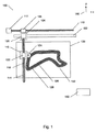
ここで図1を参照すると、業界で現在知られている付加型製造デバイス100の典型的なレイアウトの上面図が表される。基準座標系は、参照番号190によって示される。
Referring now to FIG. 1, a top view of a typical layout of
書き込みヘッド124が、キャリッジ116を含む駆動機構に取り付けられる。キャリッジ116には書き込みヘッド124が接続される。キャリッジ116は、軌道114に沿って摺動するべく構成される。駆動機構はまた、キャリッジ104に取り付けられてねじ118を駆動するモータ120も含む。ねじ118は、キャリッジ116に接続されたナット122を動かすべく構成される。モータ120がアクティブになると、ねじ118を回転させてキャリッジ116と、キャリッジ116に関連付けられた組み付け体とを軌道114沿いに動かす。コンピュータ180は、モータ120を制御することにより、書き込みヘッド124を軌道114に沿ってY軸方向に、異なる速度及び精度で動かす指令を発することができる。
A
書き込みヘッド124の駆動機構はまた、X軸方向に可動なキャリッジ104を有する軌道102も含む。ナット108がキャリッジ104に接続され、ねじ110により駆動され得る。ねじ110は、コンピュータ180により制御されてヘッド124をX軸方向に動かすべく構成されたモータ112に接続される。
The drive mechanism for the
装置の他例において、番号108及び110は非拘束型線形アクチュエータを示す。ここで、108はモータであり、ねじ110が、固定要素112又は任意の他の線形アクチュエータに締結される。他の周知の線形動アクチュエータを用いて、書き込み又は材料供給ヘッド124を動かすことができる。
In another example of the device, the
動きコントローラ及びモータドライバを介するのが典型的なコンピュータ180の接続部は、業界周知の技術であるため、図面を簡潔にするべく図示しない。コンピュータ180はまた、少なくとも一つの進行軌跡と、例えばヘッド124のような少なくとも一つの材料供給又は書き込みヘッドの少なくとも一つの材料供給機能とを計画(又は生成)及び制御するべく構成される。
The connections of the
プレート130は、構成中の3Dオブジェクト132を支持する。プレート130は、製造対象の3Dオブジェクトに対する一つの支持平面を与え得る。ただし、製造対象の3Dオブジェクトの異なる部分を支持するべく、多重の起伏付き支持平面を与えてもよい。プレート130は、当該プレートの平面に直交するZ軸方向に動くことにより、異なる層が、書き込み要素からZ方向の適切な距離に配置されて書き込まれるようにできる。第1層126は、プレート130に接触する最下層である。この例において、層128は、3Dオブジェクト書き込みプロセスにおける6番目(第6)層であり、現在のところ3Dオブジェクトの最上層であり、現在のところ書き込み中である。図1において、書き込みヘッド124は、層128及び他の層を、装置100にとって典型的な書き込みレートで書き込む。装置100によって層128を完成する時間がT(6)として示される。単一の書き込みヘッドを使用して層iを完成する時間がT(i)として示される。
The
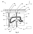
本開示に係る装置の一例が図2に示される。図2は、層を書き込んで少なくとも一つの3Dオブジェクトを構成又は構築するべく構成された2つの材料供給又は書き込みヘッドと、各材料供給又は書き込みヘッドを、3Dオブジェクトの支持体130に対して動かすべく構成された駆動機構とを含む装置200を示す。装置200は、書き込み層128の一フェーズにあるところを示す(他の層に対する記載も同様である)。書き込みヘッド224を担持する組み付け体が、第2書き込みヘッドを装置に与えるべく付加される。ナット208が、ナット108と同じねじ110に組み付けられるので、双方の書き込みヘッド124及び224が、ねじ110によってX軸に沿って動くことができる一方、書き込みヘッド124及び224間のX軸方向距離は固定される。書き込みヘッド124及び224はそれぞれ、互いに独立にY軸に沿って動くこともできる。駆動機構はまた、材料供給/書き込み機能の少なくとも一部に対し、2つの材料供給/書き込みヘッド124及び224を同時に動かすべく構成される。
An example of an apparatus according to the present disclosure is shown in FIG. FIG. 2 shows two material supply or write heads configured to write a layer to construct or construct at least one 3D object, and to move each material supply or write head relative to the
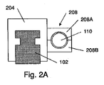
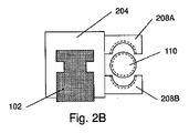
この配列により、書き込みヘッド124及び224は、層128(又は任意の他の層)の別個のセグメントの少なくとも一部を同時に書き込む(この例においては材料を供給する)ことができる。セグメント群及びその書き込みヘッド124及び224への割り当てを適切に設計することにより、各書き込みヘッドを、層128(又は任意の他の層)のセグメント長さ全体の類似部分の長さを書き込むべく割り当て又は配分することができる。したがって、類似のスループットの2つの書き込みヘッドを使用して層128を完成する時間を、一つの書き込みヘッドを使用して層128を完成するのに必要な時間の半分T(6)/2まで低減することができる。層セグメントを2つの書き込みヘッド間で共有する適切な設計は、書き込み予定の3Dオブジェクトのサイズに対する当該書き込みヘッド間のX軸方向に沿った距離に依存する。例えばナット208を参照して示されるような機構により、X軸方向に沿った書き込みヘッド間の距離が調整される。図2Aにおいてナット208は、軌道102方向でもあるX軸方向から観察されるように示される。ナット208は、上半分208A及び下半分208Bに分割される。双方の部分は、図2Aにおいて、ねじ110を閉じるように接続される。ねじ110が静止したままの場合、ナット208は動かず、ナット208に接続されたキャリッジ204も動かない。図2Bにおいて、ナット208の2つの部分が、部分208Aを上にかつ部分208Bを下に動かすことにより分離される。ここでキャリッジ204がねじ110から解放されるので、製造対象の3Dオブジェクトの寸法に応じて書き込みヘッド124及び224間のX方向(軌道102方向)距離を調整するべく、キャリッジ204を軌道102に沿って動かすことができる。典型的には、当該距離は、3DオブジェクトのX軸方向寸法の約半分へと調整される。その後、ナットの部分208A及び208Bは、図2Aに示されるように閉じられ、書き込みヘッド124及び224間の距離が設定される。
This arrangement allows write heads 124 and 224 to simultaneously write (provide materials in this example) at least some of the separate segments of layer 128 (or any other layer). By appropriately designing the segments and their assignment to write
いくつかの例において、書き込みヘッド124の組み付け体に関連付けられた要素(例えばキャリッジ116、ナット122及び書き込みヘッド124)が、書き込みヘッド224の組み付け体に関連付けられた要素(例えばキャリッジ216、ナット222及び書き込みヘッド224)と衝突することのないように、ナット108及び208間の最小距離を設定する制限デバイスを構成することが望まれる。これは、例えば、ねじ110が挿入される制限管(図示しない)によって行い得る。当該管は、ナット108及び208間のねじ上に配置することができ、書き込みヘッド124及び224間の距離の調整中にナット108及び208が互いに近くなりすぎることを防止する長さとし得る。かかる最小距離制限デバイス/管を使用して、書き込みヘッド124及び224は、生じ得る衝突から保護することができる。
In some examples, the elements associated with the assembly of write head 124 (eg,
書き込みヘッド124及び224のX軸方向結合により、当該書き込みヘッドの移動速度に一定の制限が課され、いくつかの場合、当該書き込みヘッドそれぞれは、自身のセグメントに対して同じ速度で動くことができない。かかる場合の一例は、書き込みヘッド124がY軸方向のセグメントの一区画を書き込んでいるのと同時に、書き込みヘッド224はX軸方向のセグメントの一区画に面している場合である。書き込みヘッド124及び224がX軸方向に結合されるので、書き込みヘッド224は、書き込みヘッド124がその対応するY軸方向のセグメント区画を完成するまで、そのX軸方向セグメントの区画に沿って動くことができない。この制限を克服するべく、書き込みヘッド224による材料供給を、書き込みヘッド124がX軸方向に動く準備ができるまで保留にすることができる。これは、2つの書き込みヘッド124及び224の少なくとも一方に対して可変書き込み速度を使用することにより実装することができる(例えば、書き込み単位長さ当たりに3Dオブジェクトに付加される材料の量を可変にすることができる)。代替的に、書き込み軌跡及びセグメントの計画は、所与の時間で書き込まれるべき区画同士が互いに直交する状況を最小限にするようにして行うこともできる。これは、一方の材料供給ヘッドが、他方の書き込みヘッドがその直交方向材料押し出しを完了するまで、一つの方向の材料押し出しを停止しなければならない状況を回避するのに役立つ。
The X-axis coupling of the write heads 124 and 224 imposes certain limits on the speed of movement of the write head, and in some cases, each of the write heads cannot move at the same speed relative to its segment. . An example of such a case is when the
さらなる例において、2つの書き込みヘッド間の、X軸方向の結合を解除又は低減することができる。 In a further example, the X-axis coupling between the two write heads can be released or reduced.
装置の一例において、書き込み又は材料供給ヘッドの少なくとも一方の書き込み速度(例えば、材料押し出し法における材料押し出しレート、又は樹脂硬化法における硬化放射線強度)を調整するべく、可変書き込み速度の書き込みヘッドを使用することができる。 In one example of the apparatus, a variable write speed write head is used to adjust the write speed of at least one of the write or material delivery head (eg, material extrusion rate in the material extrusion method, or curing radiation intensity in the resin curing method). be able to.
書き込みの計画は、所与の時間で書き込まれるべき区画同士が互いに直交する状況を最小限にすることが目的とされ、2つの書き込みヘッドからの高い平均書き込み速度を達成することにより層iの書き込み時間をできるだけ低減してT(i)未満にするべく使用することもできる。 The write plan is aimed at minimizing the situation where the partitions to be written at a given time are orthogonal to each other, and writing layer i by achieving a high average write speed from the two write heads. It can also be used to reduce the time as much as possible to less than T (i).
なお、3Dオブジェクト層、例えば層6の書き込みを共有してT(6)/2にするべく、2つを超える書き込みヘッドを軌道102に組み付けることもできる。書き込み時間は、T(6)/nまで低減することができる。ここで、nは、搭載された書き込みヘッドの数である。セグメント群を、異なるセグメント群の書き込み完了時間が類似するように計画することにより、層の書き込み時間を最小にすることができる。
It should be noted that more than two write heads can be assembled to the
図2に示される単一の軌道及び単一のねじの同じ構造を使用して書き込みヘッド124及び224を非結合にすることは、非拘束型線形アクチュエータを使用することにより行うことができる。例えば、モータ112を取り外してねじ110を、回転しないように固定することができる。ナット108及び208は、非拘束型線形アクチュエータに置換することができる。それぞれの非拘束型線形アクチュエータは、他方から独立したコンピュータ180によって制御される。したがって、コンピュータ108は、X軸方向に沿った書き込みヘッド124及び224間の距離を、書き込みプロセス中又は任意の他の時間中に制御して変更することができる。なお、X軸方向に沿った書き込みヘッド124及び224の独立した動きを得るべく、ねじ110をラック及びピニオンのシステムに置換することのような他のソリューションも使用することができる。モータが、キャリッジ104及び204に取り付けられてヘッド124及び224を、X軸方向に沿ったガイド上を独立的に駆動かつ移動させる。他例において、一つの部品が軌道及びラックの双方を構成することにより、軌道とは別個のねじ110又はラックのような付加部品が存在しないように、ラックを軌道102の一体部品とすることができる。
Decoupling the write heads 124 and 224 using the same structure of a single track and single screw shown in FIG. 2 can be done by using an unconstrained linear actuator. For example, the
図3は、2つの書き込みヘッド124及び224が結合されておらず、かつ、各書き込みヘッドが他方から独立して任意方向に可動な(当該書き込みヘッドと装置の他の部分との衝突が回避される限りにおいて)装置の一例である。 FIG. 3 shows that the two write heads 124 and 224 are not coupled and each write head is movable in any direction independently of the other (the collision of the write head with the rest of the device is avoided). (As far as possible) is an example of an apparatus.
書き込みヘッド224の組み付け体は、別個の駆動機構を有するにもかかわらず、書き込みヘッド124と同じ軌道102に取り付けることができる。この例において、キャリッジ204は、ブリッジ204を介してナット308に接続される。ナット308は、モータ312により駆動されるねじ310に結合される。
The assembly of the
この配列により書き込みヘッド124及び224は、相互間距離が、装置の特定の設計と2つの書き込みヘッドの特定の相対位置とに依存して最小距離を上回る限り、xy平面において独立して動くことができる。この配列によればまた、2つの書き込みヘッドは、互いに直交するセグメントの区画を、各書き込みヘッドが十分な書き込み速度で書き込むことができる。これにより層iの書き込み計画に大きな柔軟性が得られるので、図2の例と比べ、T(i)/2に近い短い書き込み時間が達成される。 This arrangement allows the write heads 124 and 224 to move independently in the xy plane as long as the distance between them exceeds the minimum distance depending on the specific design of the device and the specific relative position of the two write heads. it can. This arrangement also allows two write heads to write segments of segments that are orthogonal to each other at a sufficient write speed for each write head. This provides great flexibility in the write plan for layer i, so that a shorter write time close to T (i) / 2 is achieved compared to the example of FIG.
図3の例において、書き込み又は材料供給ヘッド224は、キャリッジ216の左側に組み付けられるので、図2の例よりも密接な書き込みヘッド間距離がサポートされ、層の書き込み計画において良好な書き込み時間最適化もサポートされる。ヘッド224はまた、キャリッジ216の右側に組み付けることもできる。かかる考慮は、付加型書き込みヘッドが装置に加えられる場合に変更され得る。
In the example of FIG. 3, the write or
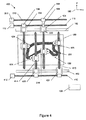
図4は、4つの書き込みヘッドを有する装置の一例である。図4は、図3の例のように非結合にされた2つの書き込みヘッド(124及び224)(この例において書き込みヘッド224はキャリッジ216の右側に組み付けられる)と、図2の例に示されるのと同様にねじ410を介して結合された2つの書き込みヘッド(420及び421)とを表す。本例において、書き込みヘッド124及び224はそれぞれ互いの書き込みヘッドから独立して可動であり、書き込みヘッド224及び225は、書き込みヘッド124及び224から独立して可動である。書き込みヘッド224及び225は、Y軸方向において互いに独立して可動な一方、X軸方向においてはねじ410を介して結合される。
FIG. 4 is an example of an apparatus having four write heads. FIG. 4 is shown in the example of FIG. 2 with two write heads (124 and 224) that are uncoupled as in the example of FIG. 3 (in this example the
なお、図4の例は、装置の実装の柔軟性を強調するべく与えられ、任意数の書き込みヘッドを結合又は非結合で実装可能である。例えば、一つのねじ410を使用して書き込み又は材料供給ヘッド424及び425を付加する代わりに、これらの書き込みヘッドの組み付けは、書き込みヘッド124及び224に類似する二重ねじ組み付け体を使用して行うことができる。その結果、4つの書き込みヘッドのそれぞれが他の3つの書き込みヘッドから独立して可能となる実装が与えられる。本開示は、これらの特定の実装のいずれにも、この例における書き込みヘッドの数にも限られない。
Note that the example of FIG. 4 is provided to emphasize the flexibility of the device implementation, and any number of write heads can be implemented with or without coupling. For example, instead of using a
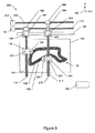
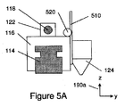
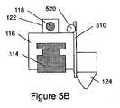
図5、5A及び5Bの例において、少なくとも一つの書き込みヘッドは、Z軸方向に動く能力を有する。この例は、図3の装置を参照して記載される。ただし、これは図3の装置に限られず、本明細書に示される例のいずれにも十分に適用可能である。図5A及び5Bを参照して詳述されるように、書き込みヘッド124はZ軸方向に可動である。図5Aにおいて、キャリッジ116、及び駆動ねじ118の断面とともに、軌道114の断面が示される。書き込みヘッド124が、スライダ510を介してキャリッジ116に接続され、モータ520は、コンピュータ180により制御されるとともに、スライダ510をZ軸方向(座標系190a参照)に動かし、ひいては書き込みヘッド124をZ軸方向に動かすべく構成される。
In the examples of FIGS. 5, 5A and 5B, at least one write head has the ability to move in the Z-axis direction. This example will be described with reference to the apparatus of FIG. However, this is not limited to the apparatus of FIG. 3 and can be applied to any of the examples shown in this specification. As described in detail with reference to FIGS. 5A and 5B, the
この配列により、図5の装置は、一を超える層を一度に書き込むべく使用することができる。図5の例において、4つの層が、すでに書き込まれて示される。第1層は参照番号126によって示される。この例において、層127の約半分(破線で示される左側)が、書き込みヘッド224によって書き込み完了している。書き込みヘッド224が層127を書き込んでいる間、一つの層のZ軸方向距離に位置決めされた書き込みヘッド124が、書き込みヘッド224により書き込まれた層の上方において、すでに書き込まれた層127の頂部に層128を書き込んでいる。図5Bは、図5Aの書き込みヘッド124の位置に対し、Z軸に沿った他の位置にある書き込みヘッド124の一例を示す。
This arrangement allows the device of FIG. 5 to be used to write more than one layer at a time. In the example of FIG. 5, four layers are shown already written. The first layer is indicated by
なお、書き込みヘッド間の層の(Z軸方向の)分離は、一つの層に限られない。書き込みヘッド間の任意のZ方向分離距離を使用することができる。 Note that the separation (in the Z-axis direction) of the layers between the write heads is not limited to one layer. Any Z-direction separation distance between the write heads can be used.
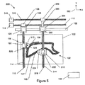
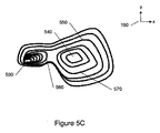
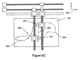
図5Cに示される例において、ピーク530及び540を有する二重ピークの3Dオブジェクトが示される。2つの非接続層セグメント560及び570に分離される前の最後の層が層550である。層550の書き込みに引き続き、書き込みヘッド124は、例えば層560により開始する左ピーク530の層を書き込むことに割り当てることができる。ピーク530の書き込みは、長い長さの少ない層のピーク540と比べ、短い長さの多くの層を特徴とする。同時に、書き込みヘッド224は、少数の長い輪郭から構成されるピーク540を書く(この例においては材料を供給する)ように割り当てることができる。書き込みヘッド124がその各層を、Z方向の移動能力ゆえに書き込みヘッド224よりも短時間に完成させるので、書き込みヘッド124が、Z方向沿いの高いところに存在する層まで可動な一方、書き込みヘッド224は依然として、Z方向に沿いの低い高さにある層の書き込みに従事する。書き込みプロセス中、時間が経過すると、書き込みヘッド124及び書き込みヘッド224間のZ軸方向の離間距離が、多重の層の厚さとなる。書き込みヘッド224が長い輪郭に割り当てられた書き込みを完了するのを、書き込みヘッド124が待つ必要がないことから、全体的な書き込み時間が短縮化される。
In the example shown in FIG. 5C, a double peak 3D object with
2つを超える書き込みヘッドにより、多数の層間差異設定を、様々な書き込みヘッド間で使用することができる。 With more than two write heads, multiple interlayer difference settings can be used between the various write heads.
本装置の多重の書き込みヘッドは、3Dオブジェクトの書き込み時間を低減するべく動作可能である。3Dオブジェクトの書き込み時間を最小限にするべく、異なるセグメントの様々な時間での書き込みをスケジューリングする様々な方法を、本装置とともに機能するように実装することができる。考慮点は、層形状、層長さ、機械的制約、及び本開示により構成される任意の特定装置の性能特徴を含み得る。かかる方法の例を以下に述べる。 The multiple write heads of the apparatus are operable to reduce the write time for 3D objects. Various methods of scheduling writing of different segments at different times can be implemented to work with the apparatus to minimize the writing time of 3D objects. Considerations may include layer shape, layer length, mechanical constraints, and performance characteristics of any particular device configured in accordance with the present disclosure. An example of such a method is described below.
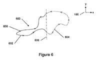
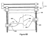
図6を参照する。これは、本開示に係る装置の一例であり、2つの書き込みヘッドを有する本装置により書き込みシーケンスを設計する一例を与える。かかる書き込み又は材料堆積の計画の説明は、本説明で書き込まれるすべてのセグメントが同じ層に属する一つの層を参照する。装置の線図は、図6において、図面の明確さを維持するべく省略され、図1〜5Cのものに類似する輪郭のみが示される(図5の輪郭126)。他の図において、図1〜5Cの装置サンプルの部分的な要素が、説明の明確のため必要とされる可能な変更とともに、明確さを目的として付加され得る。
Please refer to FIG. This is an example of an apparatus according to the present disclosure and gives an example of designing a write sequence with this apparatus having two write heads. The description of such a writing or material deposition plan refers to one layer in which all segments written in this description belong to the same layer. The diagram of the device is omitted in FIG. 6 to maintain the clarity of the drawing and only a contour similar to that of FIGS. 1-5C is shown (
図6において、層600が2つのセグメント群に分割され、一方の群がセグメント602を含み、他方の群がセグメント604を含む。Y軸に平行な分割線606によりなされる分割が、セグメント602の長さがセグメント604の長さに類似するようになる箇所に存在する。一つが参照番号608によって示される矢印が、特定のセグメント上の書き込みヘッドの動き方向を指し示す。この例において、書き込み計画は、少なくとも2つの書き込みヘッドの材料供給開始点が、類似する方向(この例においてはX軸方向)に沿って分離され、中間材料供給点が、他の方向(この例においてはY方向)に分離されるように行われる。
In FIG. 6,
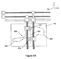
図6Aは、書き込み層600の開始点の一例を示す。書き込みヘッド124はセグメント602の開始点に位置決めされ、書き込みヘッド224はセグメント604の開始点に位置決めされる。双方の書き込みヘッドは、矢印により示される方向への対応セグメントの書き込みを開始することができる。
FIG. 6A shows an example of the starting point of the
典型的に、双方の書き込みヘッドは、同じ時刻に始動するが、これは装置を制限しない。いくつかの場合、機械的制約又は他の考慮点が、書き込み時間に影響し得る。一方の書き込みヘッドは、所定の時刻t1にその開始位置に入り、適切な時刻t2に書き込みを開始する。他方の書き込みヘッドは、時刻t3にその開始位置に入り、時刻t4に書き込みを開始する。t1、t2、t3及びt4間で任意の関係を計画することができる。例えば、t1=t2=t3=t4、t1=t2<t3<t4、t1<t2=t3<t4、t1=t2<t3=t4、t1=t2>t3=t4、又はt1<t2>t3=t4となる。 Typically, both write heads start at the same time, but this does not limit the device. In some cases, mechanical constraints or other considerations can affect write time. One write head enters its start position at a predetermined time t 1 and starts writing at an appropriate time t 2 . The other write head to enter its start position and time t 3, to start writing to the time t 4. Any relationship between t 1 , t 2 , t 3 and t 4 can be planned. For example, t 1 = t 2 = t 3 = t 4 , t 1 = t 2 <t 3 <t 4 , t 1 <t 2 = t 3 <t 4 , t 1 = t 2 <t 3 = t 4 , t 1 = t 2> t 3 = t 4, or a t 1 <t 2> t 3 = t 4.
図6Aの例において、書き込みヘッド124は、t1においてセグメント602の開始点に位置決めされ、t2においてセグメント602の書き込みを、セグメント602の矢印の方向に開始する。書き込みヘッド224は、t3においてセグメント604の開始点に位置決めされ、t4においてセグメント604の書き込みを、セグメント604の矢印の方向に開始する。この例において、時刻は、t1=t2=t3=t4となるように選択されている。したがって、書き込みヘッド124及び224は、同じ速度で書き込みかつセグメントが類似の長さであるとの仮定のもと、セグメント602及び604の書き込みを同時に開始し、図6Bに示されるように、類似の時刻において、セグメントの半分が完成する点に到達する。図6Cに示されるように、各書き込みヘッドは、その対応セグメントを、他方の書き込みヘッドと類似の時刻に完成させる。図6Cにおいて、書き込みヘッド124は、書き込みヘッド224の開始点において書き込みを完成させ、書き込みヘッド224は、書き込みヘッド124の開始点において書き込みを終了している。この例において、書き込みヘッド124及び224の軌跡は、2つの書き込みヘッド間の衝突を防止するべく計画される。X方向の分離が小さい場合(図6A)に当該書き込みヘッド間のY軸方向沿いの分離から開始し、その後、書き込みヘッドがX方向に沿って離れるように動くにつれて、図6Bに示されるようにY方向に自由に動くことができる。Y方向に沿った分離は、2つの書き込みヘッドがX方向に沿って再び近くなるとき、図6Cにおいて再び計画される。
In the example of FIG. 6A,
この例において、記載の書き込みヘッド124及び224による層600の書き込み時間は、一つの書き込みヘッドによる層600の書き込みにかかる時間の約半分となる。
In this example, the writing time of
なお、付加型書き込みヘッドを使用することにより、図4に記載された4つの書き込みヘッドに対する一つのかかる例は、層600の書き込み時間をさらに低減し得る。
Note that by using an additional write head, one such example for the four write heads described in FIG. 4 can further reduce the write time of
またもなお、セグメント602及び604の開始点は、線606に沿って示される図6の例と同じX座標にある必要はない。開始点及びセグメントの計画は、可能な制約及び特定の装置実装を満たすべく異なり得る。かかる例が図7に示される。
Again, the starting points of
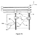
望ましいのは、書き込みヘッド124及び224が、層600を書き込む時点で互いから類似の(又は少なくとも十分な)X軸方向距離を維持するように書き込みシーケンスを計画することである。この要件をサポートするべく、層600は、2つのセグメント群に分割することができる。各群は特定の書き込みヘッドに割り当てられる。書き込みヘッド124は、動きをV字部分702aから開始してV字部分704aで終了するセグメント702の群に割り当てられる。書き込みヘッド224は、セグメント704(V字部分404aから開始してV字部分706aで終了)、及びセグメント706(V字部分406aから開始してV字部分702aで終了)の2つのセグメントを含む群に割り当てられる。
Desirably, the write sequence is planned so that the write heads 124 and 224 maintain a similar (or at least sufficient) X-axis distance from each other when writing the
書き込みヘッド124及び224の最初の書き込み位置が図7Aに例示される。開始時において、書き込みヘッド124はV字部分702aの箇所に位置決めされ、書き込みヘッド224はV字部分706aの箇所に位置決めされる。このように書き込みヘッド124及び224は、X軸方向に沿った3Dオブジェクト寸法の約半分に分離される。層600の書き込みが開始すると、書き込みヘッド124はセグメント702の矢印方向に書き込み、書き込みヘッド224はセグメント706の矢印方向に書き込む。書き込みヘッド224がセグメント706の端(V字部分702a箇所付近)に到達すると、書き込みヘッド124は、セグメント702上の箇所702bに到達する。書き込みヘッド224は、書き込み速度よりも高速でセグメント704の開始点、すなわちV字部分704aの点まで動き得る。この時間、書き込みヘッド124が、点702bを超えるまでセグメント702を書き込み続け、又は書き込みヘッド224が点702aから点704aへの動きを完了するのを待つ。全体的な書き込み速度を考慮すれば、書き込みヘッド124がこの時間、書き込み続ける方が好ましい。機械的構造のようないくつかの他の制約によれば、待つ方が提案され得る。この時間内に、書き込みヘッド124は点702bから点704aまでセグメント702を書き込み、書き込みヘッド224は点704aから点706aまでセグメント704を書き込む。
The initial write position of write heads 124 and 224 is illustrated in FIG. 7A. At the start, the
なお、層600の書き込みプロセス中、書き込みヘッド124及び224は、X軸方向に沿って十分に分離されている。
Note that during the writing process of
層の最小書き込み時間の最適化において、セグメントはまた、書き込みヘッド124によるセグメント702の書き込み時間が、書き込みヘッド224がセグメント706を書き込み、セグメント704の開始点まで移動し、及びセグメント704を書き込むのに必要な時間と等しく又は近似的に等しくなるように設計される。
In optimizing the layer's minimum write time, the segment also allows the write time of the
なお、上記方法は、2つを超える書き込みヘッドによって使用可能であり、(本装置の特定の実装の制約を考慮に入れて)時間のみに対して最適化し、又は書き込みヘッドを(図7を参照して記載される)層書き込み時間内に一般にできる限り分離しておく一般的アプローチを含む時間に対して最適化し得る。 It should be noted that the above method can be used with more than two write heads and is optimized only for time (taking into account the specific implementation constraints of the apparatus) or the write head (see FIG. 7). Can be optimized for time, including a general approach that is generally separated as much as possible within the layer writing time (described below).
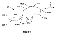
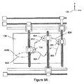
図8は、3つの書き込みヘッドを有する装置において本方法の実装を利用する書き込みシーケンス計画の一例である。この例において、層のセグメント群及び材料供給シーケンスの決定は、3つの材料供給又は書き込みヘッドを、各材料供給ヘッドによる少なくとも一つのセグメントの材料供給中にそれぞれが一つの方向に沿って隣接材料供給ヘッドから類似の距離に維持するようになされる。 FIG. 8 is an example of a write sequence plan that utilizes an implementation of the method in an apparatus having three write heads. In this example, the determination of the layer segments and the material supply sequence includes three material supply or write heads, each adjacent to one material supply along one direction during the material supply of at least one segment by each material supply head. It is designed to maintain a similar distance from the head.
図8において、層600は2つのセグメント群に分離され、各群は、図8Aにおいて124、224及び824として示される3つの書き込みヘッドの一つに割り当てられる。セグメント802を含む群は、書き込みヘッド124により書き込まれるように割り当てられる。セグメント804及び810を含む群は、書き込みヘッド824に書き込まれるように割り当てられる。セグメント806及び808を含む群は、書き込みヘッド224により書き込まれるように割り当てられる。図7及び7Aを参照して説明したように、書き込みシーケンスの最適化は、時間の最小化と、書き込みプロセス中に3つの書き込みヘッドを互いから一定距離に維持することとの双方を目的としてなされる。3つのセグメント群それぞれの全体長さは類似する。例えば、セグメント804及び810の長さの合計は、セグメント806及び808の長さの合計に類似する。書き込みを開始するべく、3つの書き込みヘッドそれぞれが、対応セグメント群のセグメント開始点に位置決めされる。
In FIG. 8,
書き込みヘッド224は、セグメント808の開始点、すなわち一般に層600の最も右側部分にである点808aに位置決めされる。
Write
一例において、3つの書き込みヘッド間の衝突を防止して書き込み時間を低減することの計画では、書き込みヘッド824が、セグメント810の開始点、すなわち、層600の最も右側部分の左において一般に層600のX軸方向寸法の約1/3となるX軸沿いの距離の点810aに位置決めされる。
In one example, in a plan to prevent collisions between three write heads and reduce write time, the
書き込みヘッド124は、セグメント802の開始点、すなわち、層600の最も右側部分の左において一般に層600のX軸方向寸法の約2/3となるX軸方向沿いの距離の点802aに位置決めされる。
Write
このように、それぞれ2つの書き込みヘッド間の空間は類似する。 Thus, the space between each two write heads is similar.
3つの書き込みヘッドはここで、材料の書き込み又は堆積を開始することができる。各一つは、書き込みヘッド224が点810aに到達し、書き込みヘッド824が点802aに到達し、及び書き込みヘッド124が点802bに近づくまで、関連セグメントにある。この段階で、書き込みヘッド224は、対応群の第2セグメント806を書き込むべく、点810aから点806aまで速いペースで動く。書き込みヘッド124は、対応群の第2セグメント804を書き込むべく、点802aから点804aまで速いペースで動く。この時点まで、セグメントの長さが適切に最適化されていれば、書き込みヘッド124が点802bに到達し、3つの書き込みヘッドはすでに書き込み又は材料堆積を続けている。書き込みヘッド224はセグメント806を書き込み続け、書き込みヘッド824はセグメント804を書き込み続け、及び書き込みヘッド124はセグメント802を完成する。
The three write heads can now start writing or depositing material. Each one is in the relevant segment until
上述したように、層600を書き込むのにかかる最小時間のためのこの最適化において、当該最適化は、書き込みヘッド224がセグメント808を書き込んでセグメント806の開始点まで動き、その後セグメント806を書き込む時間が、書き込みヘッド824がセグメント810を書き込んでセグメント804の開始点まで動き、その後セグメント804を書き込む時間に類似するように行われる。当該時間はまた、書き込みヘッド124がセグメント802を書き込むのにかかる時間にも類似する。また、この例が実証する書き込みシーケンスは、当該書き込みプロセス中に、書き込みヘッド同士を互いから一定距離に維持する。
As described above, in this optimization for the minimum time taken to write
なお、上記例のすべてにおいて、一つを超える3Dオブジェクトを一定時間に書き込むべく多重の書き込みヘッド装置を使用することができる。これは、異なる3Dオブジェクトのセグメントを、当該時間の少なくとも一部の間、異なる書き込みヘッドに割り当てることによる。 In all of the above examples, multiple write head devices can be used to write more than one 3D object in a given time. This is by assigning different 3D object segments to different write heads for at least part of the time.
なお、上記例のいずれかにおいて、一つの書き込みヘッドによる材料堆積を中断する一方で他の材料堆積又は書き込みヘッドが材料の堆積又は書き込みをし続けることも、書き込みヘッド間の衝突を回避することを可能とし得る。 In any of the above examples, the material deposition by one write head is interrupted while another material deposition or the write head keeps depositing or writing the material to avoid collision between the write heads. It can be possible.
またもなお、上記例のいずれにおいても、一つの材料堆積又は書き込みヘッドを3Dオブジェクト領域から退避させる一方、他の材料堆積書き込みヘッドに書き込みを続けさせることができる。これは、書き込みヘッド間の衝突を回避するべく使用され得る。 Still further, in any of the above examples, one material deposition or write head can be retracted from the 3D object area while another material deposition write head can continue writing. This can be used to avoid collisions between write heads.
しかしながら、材料堆積の例の説明は、例示によってなされるだけであり、本開示の範囲をこの手法に限定するわけではない。本開示は、以下のような他の技術において類似する。すなわち、樹脂硬化と、3Dオブジェクトのボトムアップ構築及びトップダウン構築技術と、3Dオブジェクトの上方に配置される書き込みヘッド又は3Dオブジェクトの下方若しくは側方に配置される書き込みヘッドと、材料供給又は堆積、材料押し出し、スパッタリング、ドリッピング(これらはすべて材料供給の特殊なケースである)、粒状材料の結合、電子ビーム直接製造及び樹脂硬化のような技術により所定体積の固体状態材料を生成する任意の他のアクションとのような技術である。 However, the description of examples of material deposition is done by way of example only and does not limit the scope of the present disclosure to this approach. The present disclosure is similar in other technologies as follows. That is, resin curing, 3D object bottom-up construction and top-down construction technology, a write head disposed above the 3D object or a write head disposed below or on the side of the 3D object, material supply or deposition, Any other that produces a given volume of solid state material by techniques such as material extrusion, sputtering, dripping (all of which are special cases of material supply), granular material bonding, electron beam direct manufacturing and resin curing. It is a technology like action.
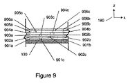
図9は、異なるセグメントが出会う領域における6層の3Dオブジェクトの一部の側面図の一例である。この領域においてプレート130と接触する層は、12のセグメントを含む。これはセグメント901a及び901bを含む。2つのセグメント901a及び901bが出会う箇所は901cとして示される。2つのセグメント902a及び902bが出会う箇所は902cとして示され、以下、2つのセグメント906a及び906bが出会う箇所が906cとして示されるまで同様である。ここで座標系190は、X方向及びZ方向を示す。
FIG. 9 is an example of a side view of a part of a 6-layer 3D object in a region where different segments meet. The layer in contact with the
層のセグメント群を計画する間にわたり、隣接セグメントの出会い箇所は、互いに対して当該層に沿ってシフトされる。その結果、セグメントが出会う箇所が連続曲線上に存在して3Dオブジェクトの輪郭に構造上の弱点が導入されることが回避される。これによれば、出会い箇所902cが出会い箇所901cに対してシフトされ、出会い箇所903cが出会い箇所902cに対してシフトされ、及び出会い箇所904cが出会い箇所903cにシフトされ、以下同様とされる。隣接する層の出会い箇所は、当該層に沿った固定又は可変距離だけ分離可能である。層のセグメントの隣接端は、例えば図9に示されるように、当該層に沿って配置されるように計画され得る。
While planning a segment group for a layer, adjacent segment encounters are shifted along the layer relative to each other. As a result, it is avoided that the location where the segments meet exists on the continuous curve and structural weak points are introduced into the outline of the 3D object. According to this, the
出会い箇所における2つの隣接セグメント間のギャップは、出会い箇所901cから904cまでの例に示されるようにゼロよりも大きい。異なるセグメントは実際には、905c及び906cに示されるように互いに接触し又は強固に接触する。異なるセグメント間のギャップは、出会い点903cに対する904cに示されるように可変であり得る。
The gap between two adjacent segments at the meeting point is greater than zero as shown in the examples of meeting points 901c through 904c. The different segments actually touch each other or make firm contact as shown at 905c and 906c. The gap between the different segments can be variable as shown at 904c for
この構造を特徴付けるのは、各層の出会い点付近におけるセグメント断面特徴が、当該出会い点からさらに離れたセグメント部分の断面特徴に類似し、実際のところ、当該セグメント全体のセグメント断面特徴に類似することである。セグメントの断面特徴は、当該セグメントの一端から他端まで類似する。 This structure is characterized by the fact that the segment cross-sectional feature near the meeting point of each layer resembles the cross-sectional feature of the segment further away from the meeting point, and in fact, resembles the segment cross-sectional feature of the entire segment. is there. The cross-sectional characteristics of the segment are similar from one end of the segment to the other.
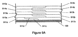
図9Aの例において、異なる層セグメントの出会い領域における界面の計画は、セグメント911a(当該図には存在せず)の断面特徴が当該セグメントに沿って変化するように行われる。左部分では所定の高さを有し、区画911cに近づくとセグメントの高さが低くなる。この界面計画において、低くされた高さは、セグメント911aと同様に右部分に類似の所定高さを有するセグメント911bによって完成される。区画911dにおいて、セグメントの高さは低くなり、部分911c及び911dが一緒になって、区画911bの右部分及び区画911aの左側に類似の断面を有する結合区画をもたらすように、911dが911cの上に書き込まれる。このように、結合された2つのセグメントにより、出会い領域(911c及び911dが一緒に存在する領域)から離れた各セグメントの所定高さに類似する高さが得られる。911a及び911cの結合断面は、界面範囲から外のセグメントの断面に類似する。セグメントの低い高さは、セグメントの単位長さ当たり可変量の材料を供給し、ひいては可変厚さのセグメントを書き込むような可変書き込み速度を有する書き込みヘッドにより与えることができる。
In the example of FIG. 9A, the interface planning in the encounter region of different layer segments is done so that the cross-sectional characteristics of the
セグメント912a及び912bに対して示されるように、セグメント同士が重なる出会い領域は、一つの層における層輪郭に沿って他の層に対する他の箇所へとシフトさせることができる。
As shown for
セグメント915a及び915bに対して示されるように、当該セグメントが重なる出会い領域において、セグメントの鉛直方向の順番が逆転され得る。上述の層において、右セグメントは左セグメントの頂部に載置される。915a及び915bのセグメント例において、左セグメントは右セグメントの頂部に載置される。
As shown for
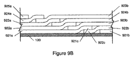
図9Bは、セグメント断面特徴(図示せず)が、当該セグメントに沿って類似のままとなる一例を示す。ただし、2つのセグメントの出会い領域において、一つのセグメントの失われた高さが、重なる層の高さによって補完される。これにより、挟み込み出会い区画を有する種類の層が形成される。一例において、セグメント921bが最初に書き込まれ、その後セグメント922bが、その一部分である922cがセグメント921bの層レベルに存在し他の部分がセグメント921bの頂部に存在するように書き込まれる。その後、セグメント921aが、その一部分がセグメント921bと同じ高さとなるように書き込まれ、その端部分である921cが922cの頂部に書き込まれる。このプロセスは、図9Bに示されるような挟み込み出会い箇所の構造をもたらすべく、セグメントの残りについて続けられる。また、この例では、一つの層からのセグメントの、隣接層からのセグメントとの出会い領域において、各セグメント箇所は、他のセグメントの層に変化する。
FIG. 9B shows an example where segment cross-sectional features (not shown) remain similar along the segment. However, in the meeting area of two segments, the lost height of one segment is complemented by the height of the overlapping layers. As a result, a kind of layer having sandwiched encounter sections is formed. In one example,
なお、本開示に記載される書き込み技術は、例としてのみ与えられ、方法及び装置の範囲を制限しない。書き込み技術は、任意の付加型製造法からなり得る。これは、樹脂硬化用のレーザー源及びレンズ、熱源、UV源、マイクロ波源、材料堆積と組み合わせられた電子ビーム源、及び堆積/供給材料を固化するべく構成された他の源、材料固化、材料の供給又はスパッタリング用のノズル又はオリフィスに限られない。書き込み要素は、書き込み単位長さ当たり3Dオブジェクトに付加される材料の量が一定となる固定書き込み速度とし得る。書き込み要素は、書き込み単位長さ当たり3Dオブジェクトに付加される材料の量が可変となる可変書き込み速度とし得る。
Note that the writing techniques described in this disclosure are given by way of example only and do not limit the scope of the method and apparatus. The writing technique can consist of any additive manufacturing method. This includes laser sources and lenses for resin curing, heat sources, UV sources, microwave sources, electron beam sources combined with material deposition, and other sources configured to solidify deposition / feed materials, material solidification, materials It is not limited to nozzles or orifices for supplying or sputtering. The writing element may be a fixed writing speed where the amount of material added to the 3D object per writing unit length is constant. The writing element may have a variable writing speed that varies the amount of material added to the 3D object per writing unit length.
Claims (13)
材料を堆積させて3Dオブジェクトの少なくとも一つの、別個のセグメントを含む材料層を形成するべく構成された少なくとも2つの独立駆動材料供給ヘッドと、
構成される3Dオブジェクトの少なくとも一つの材料層を支持するべく構成された支持体に対し、前記少なくとも2つの独立駆動材料供給ヘッドを動かすべく構成された駆動機構と
を含み、
前記少なくとも2つの独立駆動材料供給ヘッドの第1材料供給ヘッド及び第2材料供給ヘッドがそれぞれ、一定の高さを有する材料層の長さに沿って延びる第1セグメント及び第2セグメントを形成するべく構成され、
前記第1材料供給ヘッド及び前記第2材料供給ヘッドは、前記第1セグメントと前記第2セグメントとが互いに重なる出会い領域において、前記第1セグメント及び前記第2セグメントそれぞれを形成するための材料供給を、各セグメントの高さが前記長さに沿って連続的に変化するように調整するべく構成される装置。 Add-on manufacturing equipment,
At least two independently driven material delivery heads configured to deposit material to form a material layer comprising at least one separate segment of the 3D object;
A drive mechanism configured to move the at least two independent drive material supply heads relative to a support configured to support at least one material layer of the configured 3D object;
The first material supply head and the second material supply head of the at least two independently driven material supply heads respectively form a first segment and a second segment extending along the length of the material layer having a constant height. Configured,
The first material supply head and the second material supply head supply materials for forming the first segment and the second segment, respectively, in an encounter region where the first segment and the second segment overlap each other. An apparatus configured to adjust the height of each segment to vary continuously along the length .
前記2つの独立駆動材料供給ヘッド間の前記軌道に沿った距離は調整可能である請求項1に記載の装置。 Two of the independently driven material supply heads are disposed along a track at a distance from each other;
The apparatus of claim 1, wherein a distance along the trajectory between the two independently driven material supply heads is adjustable.
前記材料固化放射線源は、紫外放射線源、赤外放射線源及び熱源からなる材料固化源群の一つである請求項1に記載の装置。 And further comprising at least one material solidifying radiation source,
The apparatus according to claim 1, wherein the material solidification radiation source is one of a material solidification source group including an ultraviolet radiation source, an infrared radiation source, and a heat source.
材料を堆積させて同じ3Dオブジェクトの少なくとも一つの層を形成するべく構成された少なくとも2つの独立駆動材料供給ヘッドと、
構成される3Dオブジェクトの少なくとも一つの層を支持するべく構成された支持体に対し、前記少なくとも2つの独立駆動材料供給ヘッドを動かすべく構成された駆動機構と、
前記少なくとも2つの独立駆動材料供給ヘッドのそれぞれの、少なくとも一つの供給ヘッド進行軌跡、及び材料供給機能を、生成及び制御するべく構成されたコンピュータと
を含み、
前記少なくとも2つの独立駆動材料供給ヘッドは、同じ層の別個のセグメントの少なくとも一部に材料を供給するべく構成され、
前記少なくとも2つの独立駆動材料供給ヘッドは、前記別個のセグメントを形成するための材料供給の速度及び量を可変にすることによって、前記別個のセグメントの出会い領域を形成するべく構成される装置。 Add-on manufacturing equipment,
At least two independently driven material delivery heads configured to deposit material to form at least one layer of the same 3D object;
A drive mechanism configured to move the at least two independent drive material delivery heads relative to a support configured to support at least one layer of the configured 3D object;
Wherein wherein each of the at least two independently driven material application head, at least one feed head traveling locus, the及beauty materials supply function, and a computer configured to generate and control,
It said at least two independently driven material application head is configured to supply the wood charge to at least a portion of the discrete segments of the same layer,
The apparatus wherein the at least two independently driven material supply heads are configured to form an encounter region of the separate segments by varying the rate and amount of material supply to form the separate segments.
材料を堆積させて同じ3Dオブジェクトの少なくとも一つの層を形成するべく構成された少なくとも2つの独立駆動材料供給ヘッドと、
構成される3Dオブジェクトの少なくとも一つの材料層を支持するべく構成された支持体に対し、前記少なくとも2つの独立駆動材料供給ヘッドを動かすべく構成された駆動機構と、
前記少なくとも2つの独立駆動材料供給ヘッドのそれぞれの、少なくとも一つの供給ヘッド進行軌跡、及び材料供給機能を、生成及び制御するべく構成されたコンピュータと
を含み、
前記少なくとも2つの独立駆動材料供給ヘッドは、同じ層の別個のセグメントの少なくとも一部に材料を供給するべく構成され、
前記同じ層の別個のセグメントの少なくとも2つが、その2つのセグメントの出会い領域を有し、
前記少なくとも2つの独立駆動材料供給ヘッドが、前記別個のセグメントを形成するための材料供給の速度及び量を可変にすることによって、前記出会い領域において、前記少なくとも2つの一方のセグメントの高さと他方のセグメントの高さとが補完し合って前記同じ層の高さが維持される装置。 Add-on manufacturing equipment,
At least two independently driven material delivery heads configured to deposit material to form at least one layer of the same 3D object;
A drive mechanism configured to move the at least two independent drive material supply heads relative to a support configured to support at least one material layer of the configured 3D object;
Wherein wherein each of the at least two independently driven material application head, at least one feed head traveling locus, the及beauty materials supply function, and a computer configured to generate and control,
It said at least two independently driven material application head is configured to supply the wood charge to at least a portion of the discrete segments of the same layer,
At least two of the separate segments of the same layer have meeting areas of the two segments;
The at least two independently driven material supply heads vary the speed and amount of material supply to form the separate segments, thereby increasing the height of the at least two segments and the other in the encounter region. A device in which the heights of the segments are complemented to maintain the same layer height .
Applications Claiming Priority (3)
| Application Number | Priority Date | Filing Date | Title |
|---|---|---|---|
| US201461941494P | 2014-02-19 | 2014-02-19 | |
| US61/941,494 | 2014-02-19 | ||
| PCT/IL2015/000005 WO2015125128A1 (en) | 2014-02-19 | 2015-02-05 | Additive manufacturing device |
Publications (2)
| Publication Number | Publication Date |
|---|---|
| JP2017507813A JP2017507813A (en) | 2017-03-23 |
| JP6171107B2 true JP6171107B2 (en) | 2017-07-26 |
Family
ID=52822495
Family Applications (1)
| Application Number | Title | Priority Date | Filing Date |
|---|---|---|---|
| JP2016551854A Active JP6171107B2 (en) | 2014-02-19 | 2015-02-05 | Additive manufacturing device |
Country Status (6)
| Country | Link |
|---|---|
| US (2) | US9011136B1 (en) |
| EP (1) | EP3107711B2 (en) |
| JP (1) | JP6171107B2 (en) |
| KR (2) | KR101704373B1 (en) |
| IL (1) | IL247045B (en) |
| WO (1) | WO2015125128A1 (en) |
Families Citing this family (47)
| Publication number | Priority date | Publication date | Assignee | Title |
|---|---|---|---|---|
| EP2851179B1 (en) * | 2013-09-19 | 2017-11-22 | SDD Holding B.V. | Device for printing simultaneously three dimensional objects |
| TW201522013A (en) * | 2013-12-12 | 2015-06-16 | 三緯國際立體列印科技股份有限公司 | Three dimensional printing apparatus |
| US10252463B2 (en) * | 2014-07-22 | 2019-04-09 | Nabil A. Amro | Compact instrument with exchangeable modules for multiple microfabrication and/or nanofabrication methods |
| US20160311159A1 (en) * | 2015-04-24 | 2016-10-27 | Caterpillar Inc | System and method for forming an object using additive manufacturing process |
| CN106313529B (en) * | 2015-06-15 | 2018-08-31 | 三纬国际立体列印科技股份有限公司 | Low-melting-point material printing method of 3D printer |
| WO2017044892A1 (en) | 2015-09-11 | 2017-03-16 | Autodesk, Inc. | Multi-tool manufacturing system |
| JP6533493B2 (en) * | 2015-10-08 | 2019-06-19 | 株式会社ミマキエンジニアリング | Forming apparatus and forming method |
| US10391754B2 (en) | 2015-10-08 | 2019-08-27 | Mimaki Engineering Co., Ltd. | Forming apparatus and forming method |
| US10717263B2 (en) * | 2015-11-13 | 2020-07-21 | Paxis Llc | Additive manufacturing apparatus, system, and method |
| JP6772283B2 (en) | 2015-11-13 | 2020-10-21 | パクシス リミティッド ライアビリティー カンパニー | Add-on manufacturing equipment, systems, and methods |
| PT109710B (en) | 2016-10-28 | 2024-02-28 | Inst Superior Tecnico | MODULAR ADDITIVE MANUFACTURING SYSTEM |
| DE102016121782A1 (en) * | 2016-11-14 | 2018-05-17 | Cl Schutzrechtsverwaltungs Gmbh | Device for the additive production of three-dimensional objects |
| US20180141122A1 (en) * | 2016-11-18 | 2018-05-24 | General Electric Company | Methods and spoke supports for additive manufacturing |
| US10703083B2 (en) * | 2017-01-13 | 2020-07-07 | Autodesk, Inc. | Multi-tool scheduling for cooperative manufacturing |
| US10668534B2 (en) | 2017-03-06 | 2020-06-02 | General Electric Company | Leg elimination strategy for hatch pattern |
| US10828700B2 (en) | 2017-03-06 | 2020-11-10 | General Electric Company | Triangle hatch pattern for additive manufacturing |
| CN106956434A (en) * | 2017-04-10 | 2017-07-18 | 北京碧如蓝工贸公司 | The multi-functional 3D printer that synchronously can symmetrically print |
| US10596662B2 (en) | 2017-04-10 | 2020-03-24 | General Electric Company | Adaptive melting beam configuration for additive manufacturing |
| DE112017007421T5 (en) * | 2017-04-11 | 2020-01-09 | Advantest Corporation | Device for 3D additive manufacturing and method for additive manufacturing |
| US20180318926A1 (en) | 2017-05-03 | 2018-11-08 | Xact Metal, Inc. | Additive manufacturing apparatus |
| US11084275B2 (en) | 2017-05-05 | 2021-08-10 | Lincoln Global, Inc. | Methods and systems for hybrid deposition rate near net shape additive manufacturing |
| WO2018212193A1 (en) * | 2017-05-16 | 2018-11-22 | 東芝機械株式会社 | Additive manufacturing device and additive manufacturing method |
| KR101942497B1 (en) * | 2017-07-19 | 2019-01-25 | 이강득 | Multi feed device capable of controlling separately |
| EP3483755B1 (en) * | 2017-11-09 | 2022-07-13 | Dassault Systèmes | Additive manufacturing of a 3d part |
| US11980968B2 (en) | 2017-11-29 | 2024-05-14 | Lincoln Global, Inc. | Methods and systems for additive tool manufacturing |
| US11229953B2 (en) | 2017-11-29 | 2022-01-25 | Lincoln Global, Inc. | Methods and systems for additive manufacturing |
| US10328635B1 (en) | 2017-12-06 | 2019-06-25 | Massivit 3D Printing Technologies Ltd. | Complex shaped 3D objects fabrication |
| MX2020010507A (en) | 2018-04-06 | 2021-03-09 | Paxis Llc | Additive manufacturing apparatus, system, and method. |
| US20200038952A1 (en) * | 2018-08-02 | 2020-02-06 | American Axle & Manufacturing, Inc. | System And Method For Additive Manufacturing |
| EP3683039A1 (en) | 2019-01-21 | 2020-07-22 | Flender GmbH | Additive manufacturing method, computer program product and production device |
| US11440097B2 (en) | 2019-02-12 | 2022-09-13 | General Electric Company | Methods for additively manufacturing components using lattice support structures |
| FR3098752A1 (en) * | 2019-07-17 | 2021-01-22 | A3D L'atelier Numerique | 3D printer device using molten wire deposition technology, known as "FDM", intended for large-format professional 3D printers, in that it overcomes the low efficiency associated with this technology |
| US11826956B2 (en) | 2019-10-04 | 2023-11-28 | Kana Holdings, LLC | System and method for providing three-dimensional features on large format print products |
| IT201900021615A1 (en) * | 2019-11-19 | 2021-05-19 | Thinking Additive Ltd | Improved 3D printing machine and manufacturing method |
| WO2021099957A1 (en) * | 2019-11-18 | 2021-05-27 | Thinking Additive Limited | 3d printing machine and manufacturing method |
| DE102020107925A1 (en) | 2020-03-23 | 2021-09-23 | Kurtz Gmbh | Device for the generative production of components, in particular by means of selective melting or sintering |
| DE102020128028A1 (en) | 2020-10-23 | 2022-04-28 | Kurtz Gmbh | Device for the additive manufacturing of components, in particular by means of selective melting or sintering |
| CN115348908A (en) | 2020-03-23 | 2022-11-15 | 库尔特两合股份有限公司 | Apparatus for producing components, in particular by selective melting or sintering |
| CN111421806B (en) * | 2020-03-30 | 2021-05-04 | 江南大学 | A three-dimensional printing structure, printer and printing method of discontinuous cylindrical surface |
| EP4196311A4 (en) | 2020-08-14 | 2024-08-07 | Paxis LLC | Additive manufacturing apparatus, system, and method |
| DE102020122934A1 (en) * | 2020-09-02 | 2022-03-03 | Fachhochschule Münster | Additive manufacturing process |
| JP7624342B2 (en) * | 2021-04-22 | 2025-01-30 | 株式会社日本製鋼所 | Powder additive manufacturing device, processing method, and program |
| US11642845B2 (en) * | 2021-04-27 | 2023-05-09 | Essentium Ipco, Llc | Three-dimensional printer comprising first and second print heads and first, second, and third dividers |
| US12172379B2 (en) | 2021-08-11 | 2024-12-24 | General Electric Company | Cleaning system for additive manufacturing |
| GB2613020B8 (en) * | 2021-11-22 | 2025-09-03 | Generative Parametrics Ltd | A method of, and apparatus and system for, determining regions for an additive manufacturing system |
| DE102021133722A1 (en) | 2021-12-17 | 2023-06-22 | Kurtz Gmbh & Co. Kg | Device for the additive manufacturing of components |
| NL2033564B1 (en) * | 2022-11-18 | 2024-05-30 | Ultimaker Bv | Method of generating instructions for printing a 3D object |
Family Cites Families (23)
| Publication number | Priority date | Publication date | Assignee | Title |
|---|---|---|---|---|
| AT343167B (en) * | 1976-02-20 | 1978-05-10 | Plasser Bahnbaumasch Franz | MOBILE TRACKING MACHINE |
| US5216616A (en) * | 1989-06-26 | 1993-06-01 | Masters William E | System and method for computer automated manufacture with reduced object shape distortion |
| JP3515419B2 (en) * | 1999-04-30 | 2004-04-05 | ティーエスコーポレーション株式会社 | Optical three-dimensional molding method and apparatus |
| JP2001334581A (en) * | 2000-05-24 | 2001-12-04 | Minolta Co Ltd | 3D modeling equipment |
| JP2002018967A (en) * | 2000-07-11 | 2002-01-22 | Canon Inc | Object generation device |
| US6676878B2 (en) * | 2001-01-31 | 2004-01-13 | Electro Scientific Industries, Inc. | Laser segmented cutting |
| US20020113331A1 (en) * | 2000-12-20 | 2002-08-22 | Tan Zhang | Freeform fabrication method using extrusion of non-cross-linking reactive prepolymers |
| US6513897B2 (en) * | 2000-12-29 | 2003-02-04 | 3M Innovative Properties Co. | Multiple resolution fluid applicator and method |
| GB0227185D0 (en) * | 2002-11-21 | 2002-12-24 | Voith Fabrics Heidenheim Gmbh | Nonwoven fabric |
| CA2512011A1 (en) * | 2003-01-10 | 2004-07-29 | Qinetiq Nanomaterials Limited | Improvements in and relating to deposited structures |
| AU2003900180A0 (en) * | 2003-01-16 | 2003-01-30 | Silverbrook Research Pty Ltd | Method and apparatus (dam001) |
| JP2007518586A (en) | 2004-01-20 | 2007-07-12 | ユニバーシティ オブ サウザーン カリフォルニア | Automated construction including robotic systems |
| US7680555B2 (en) * | 2006-04-03 | 2010-03-16 | Stratasys, Inc. | Auto tip calibration in an extrusion apparatus |
| DE102007029142A1 (en) * | 2007-06-25 | 2009-01-02 | 3D-Micromac Ag | Layer application device for electrostatic layer application of a powdery material and apparatus and method for producing a three-dimensional object |
| WO2009013751A2 (en) * | 2007-07-25 | 2009-01-29 | Objet Geometries Ltd. | Solid freeform fabrication using a plurality of modeling materials |
| US8876513B2 (en) | 2008-04-25 | 2014-11-04 | 3D Systems, Inc. | Selective deposition modeling using CW UV LED curing |
| US8033811B2 (en) * | 2008-07-25 | 2011-10-11 | Stratasys, Inc. | Pantograph assembly for digital manufacturing system |
| US8465111B2 (en) | 2010-12-22 | 2013-06-18 | Stratasys, Inc. | Print head for use in fused deposition modeling system |
| EP2699406B1 (en) * | 2011-04-17 | 2020-02-19 | Stratasys Ltd. | System and method for additive manufacturing of an object |
| WO2013163585A1 (en) * | 2012-04-26 | 2013-10-31 | Northeastern University | Device and method to additively fabricate structures containing embedded electronics or sensors |
| GB2502294B (en) * | 2012-05-22 | 2015-12-09 | Mcor Technologies Ltd | Colour 3-Dimensional printing |
| US20140246809A1 (en) | 2013-03-04 | 2014-09-04 | California Institute Of Technology | Systems and methods implementing additive manufacturing processes that utilize multiple build heads |
| JP6257185B2 (en) * | 2013-06-28 | 2018-01-10 | シーメット株式会社 | 3D modeling apparatus and 3D modeling method |
-
2014
- 2014-04-30 US US14/265,619 patent/US9011136B1/en active Active
-
2015
- 2015-02-05 WO PCT/IL2015/000005 patent/WO2015125128A1/en not_active Ceased
- 2015-02-05 JP JP2016551854A patent/JP6171107B2/en active Active
- 2015-02-05 KR KR1020167020771A patent/KR101704373B1/en active Active
- 2015-02-05 EP EP15751295.5A patent/EP3107711B2/en active Active
- 2015-02-05 KR KR1020167034183A patent/KR101713508B1/en active Active
- 2015-03-17 US US14/659,962 patent/US9623607B2/en active Active
-
2016
- 2016-07-31 IL IL247045A patent/IL247045B/en unknown
Also Published As
| Publication number | Publication date |
|---|---|
| KR20160145840A (en) | 2016-12-20 |
| US9011136B1 (en) | 2015-04-21 |
| EP3107711B2 (en) | 2023-07-19 |
| US20150231827A1 (en) | 2015-08-20 |
| EP3107711A4 (en) | 2017-02-22 |
| JP2017507813A (en) | 2017-03-23 |
| WO2015125128A1 (en) | 2015-08-27 |
| IL247045A0 (en) | 2016-09-29 |
| KR101713508B1 (en) | 2017-03-07 |
| IL247045B (en) | 2021-09-30 |
| KR101704373B1 (en) | 2017-02-07 |
| US9623607B2 (en) | 2017-04-18 |
| EP3107711A1 (en) | 2016-12-28 |
| EP3107711B1 (en) | 2020-09-02 |
| KR20160098511A (en) | 2016-08-18 |
Similar Documents
| Publication | Publication Date | Title |
|---|---|---|
| JP6171107B2 (en) | Additive manufacturing device | |
| US10882291B2 (en) | Additive-manufacturing systems, apparatuses and methods | |
| US10913204B2 (en) | Device for constructing models in layers and methods thereof | |
| US10350821B2 (en) | Method and system for manufacturing a three-dimensional object by additive manufacturing | |
| US20140210137A1 (en) | Fixed Printhead Fused Filament Fabrication Printer and Method | |
| EP3532268B1 (en) | Modular additive manufacturing system | |
| US20250121564A1 (en) | Additive manufacturing system and method using robotic arms | |
| US9446558B2 (en) | Three-dimensional printing apparatus and printing head module | |
| CN103691947A (en) | Powder spreading device and powder spreading method for selective laser melting (SLM) equipment | |
| JP2018518400A (en) | Method and apparatus for three-dimensional modeling of an object having a high resolution background | |
| WO2017182928A1 (en) | Simultaneous multi-nozzle deposition | |
| US20150079217A1 (en) | Device for Printing Simultaneously Three Dimensional Objects | |
| KR20160121092A (en) | Three dimensional printing head assembly having photocuring unit | |
| JP6184927B2 (en) | Three-dimensional structure manufacturing apparatus and method | |
| WO2018096960A1 (en) | Shaping apparatus and method for manufacturing shaped article | |
| CN208133620U (en) | Lateral 3D printer | |
| US9349405B1 (en) | Methods, devices and systems for dispensing material on an electronic device | |
| AU2025220762A1 (en) | Apparatus and method for manufacturing three-dimensional objects | |
| MX2014001029A (en) | Three-dimensional printer with orthogonal supports. | |
| CN108381906A (en) | Lateral 3D printer |
Legal Events
| Date | Code | Title | Description |
|---|---|---|---|
| A521 | Request for written amendment filed |
Free format text: JAPANESE INTERMEDIATE CODE: A523 Effective date: 20160809 |
|
| A621 | Written request for application examination |
Free format text: JAPANESE INTERMEDIATE CODE: A621 Effective date: 20160809 |
|
| A871 | Explanation of circumstances concerning accelerated examination |
Free format text: JAPANESE INTERMEDIATE CODE: A871 Effective date: 20160809 |
|
| A975 | Report on accelerated examination |
Free format text: JAPANESE INTERMEDIATE CODE: A971005 Effective date: 20170110 |
|
| A131 | Notification of reasons for refusal |
Free format text: JAPANESE INTERMEDIATE CODE: A131 Effective date: 20170117 |
|
| A521 | Request for written amendment filed |
Free format text: JAPANESE INTERMEDIATE CODE: A523 Effective date: 20170406 |
|
| TRDD | Decision of grant or rejection written | ||
| A01 | Written decision to grant a patent or to grant a registration (utility model) |
Free format text: JAPANESE INTERMEDIATE CODE: A01 Effective date: 20170606 |
|
| A61 | First payment of annual fees (during grant procedure) |
Free format text: JAPANESE INTERMEDIATE CODE: A61 Effective date: 20170703 |
|
| R150 | Certificate of patent or registration of utility model |
Ref document number: 6171107 Country of ref document: JP Free format text: JAPANESE INTERMEDIATE CODE: R150 |
|
| R250 | Receipt of annual fees |
Free format text: JAPANESE INTERMEDIATE CODE: R250 |
|
| R250 | Receipt of annual fees |
Free format text: JAPANESE INTERMEDIATE CODE: R250 |
|
| R250 | Receipt of annual fees |
Free format text: JAPANESE INTERMEDIATE CODE: R250 |
|
| R250 | Receipt of annual fees |
Free format text: JAPANESE INTERMEDIATE CODE: R250 |
|
| R250 | Receipt of annual fees |
Free format text: JAPANESE INTERMEDIATE CODE: R250 |
|
| R250 | Receipt of annual fees |
Free format text: JAPANESE INTERMEDIATE CODE: R250 |