JP6170005B2 - Eddy current flaw detection method and eddy current flaw detection apparatus - Google Patents
Eddy current flaw detection method and eddy current flaw detection apparatus Download PDFInfo
- Publication number
- JP6170005B2 JP6170005B2 JP2014072769A JP2014072769A JP6170005B2 JP 6170005 B2 JP6170005 B2 JP 6170005B2 JP 2014072769 A JP2014072769 A JP 2014072769A JP 2014072769 A JP2014072769 A JP 2014072769A JP 6170005 B2 JP6170005 B2 JP 6170005B2
- Authority
- JP
- Japan
- Prior art keywords
- detection
- absolute value
- signal
- coil
- eddy current
- Prior art date
- Legal status (The legal status is an assumption and is not a legal conclusion. Google has not performed a legal analysis and makes no representation as to the accuracy of the status listed.)
- Active
Links
Images


Landscapes
- Investigating Or Analyzing Materials By The Use Of Magnetic Means (AREA)
Description
本発明は、相互誘導形標準比較方式の渦電流探傷プローブを用いた渦電流探傷方法及び渦電流探傷装置に関する。 The present invention relates to an eddy current flaw detection method and an eddy current flaw detection apparatus using a mutual induction type standard comparison eddy current flaw probe.
非破壊試験方法の一つである渦電流探傷方法は、渦電流探傷プローブの励磁コイルに励磁信号(交流)を印加して励磁し、プローブを導電性の被検査体に近づけ、電磁誘導によって被検査体に渦電流を誘起し、この渦電流の乱れ(若しくはそれに伴う磁束密度の乱れ)をプローブの検出コイルで検出する方法である(例えば特許文献1参照)。渦電流が被検査体の導電率や透磁率等で変化することから、被検査体のきず等を検知することが可能である。具体的には、例えば健全な標準試験片等に対して検出された基準検出信号を予め取得し、被検査体に対して検出された検出信号と基準検出信号との差分を画面上で表示する。検出信号の表示形態の一つとして、検出信号(電圧)を基準信号の位相と同じ成分(X成分)の電圧と90度異なる成分(Y成分)の電圧に分解してから、縦軸にX成分電圧又はY成分電圧をとり、横軸に時間又はプローブ位置をとって表示するものが知られている。そして、例えばX成分電圧又はY成分電圧が予め設定された閾値より大きい場合に、きずと判定する。 One of the nondestructive testing methods is an eddy current flaw detection method in which an excitation signal (alternating current) is applied to an excitation coil of an eddy current flaw detection probe to excite it, the probe is brought close to a conductive object to be inspected, and is subjected to electromagnetic induction. In this method, an eddy current is induced in an inspection object, and this eddy current disturbance (or magnetic flux density disturbance associated therewith) is detected by a detection coil of the probe (see, for example, Patent Document 1). Since the eddy current changes depending on the conductivity, magnetic permeability, etc. of the object to be inspected, it is possible to detect a flaw or the like of the object to be inspected. Specifically, for example, a reference detection signal detected for a healthy standard test piece or the like is acquired in advance, and the difference between the detection signal detected for the object to be inspected and the reference detection signal is displayed on the screen. . As one of the display forms of the detection signal, the detection signal (voltage) is decomposed into a voltage having the same component (X component) as the phase of the reference signal (Y component) and a voltage having a component (Y component) that is 90 degrees different from the reference signal. It is known to take a component voltage or a Y component voltage and display the time or probe position on the horizontal axis. Then, for example, when the X component voltage or the Y component voltage is larger than a preset threshold value, it is determined as a flaw.
渦電流探傷法では、きず以外の信号として、プローブと被検査体の表面との距離の変化に起因したリフトオフ信号も発生し、きず信号との識別が難しい場合がある。 In the eddy current flaw detection method, a lift-off signal due to a change in the distance between the probe and the surface of the object to be inspected is also generated as a signal other than a flaw, and it may be difficult to distinguish it from a flaw signal.
本発明の目的は、きず信号とリフトオフ信号を識別できる渦電流探傷方法及び渦電流探傷装置を提供することにある。 An object of the present invention is to provide an eddy current flaw detection method and an eddy current flaw detection device capable of discriminating a flaw signal and a lift-off signal.
上記目的を達成するために、本発明は、励磁コイル、前記励磁コイルに対して第1の並び方向に配置された第1検出コイル、及び前記励磁コイルに対して前記第1の並び方向と交差する第2の並び方向に配置された第2検出コイルを有する渦電流探傷プローブを用いた渦電流探傷方法において、前記第1検出コイルの検出信号と前記第2検出コイルの検出信号との差分を演算して差分信号を生成し、前記第1検出コイルの検出信号の絶対値及び前記第2検出コイルの検出信号の絶対値のうちの大きいほうの絶対値を前記差分信号の絶対値と比較して、前記差分信号の絶対値より小さい場合にきず有りと判定し、前記差分信号の絶対値より大きい場合にきず無しと判定する。 To achieve the above object, the present invention includes an excitation coil, a first detection coil disposed in a first arrangement direction with respect to the exciting coil, and the first alignment direction with respect to the excitation coil In an eddy current flaw detection method using an eddy current flaw detection probe having second detection coils arranged in intersecting second arrangement directions, a difference between a detection signal of the first detection coil and a detection signal of the second detection coil To generate a differential signal and compare the absolute value of the absolute value of the detection signal of the first detection coil and the absolute value of the detection signal of the second detection coil with the absolute value of the differential signal Then, it is determined that there is a flaw when it is smaller than the absolute value of the difference signal, and it is determined that there is no flaw when it is larger than the absolute value of the difference signal.
上記目的を達成するために、本発明は、励磁コイル、前記励磁コイルに対して第1の並び方向に配置された第1検出コイル、及び前記励磁コイルに対して前記第1の並び方向と交差する第2の並び方向に配置された第2検出コイルを有する渦電流探傷プローブを備えた渦電流探傷装置において、前記第1検出コイルの検出信号と前記第2検出コイルの検出信号との差分を演算して差分信号を生成する差分演算部と、前記第1検出コイルの検出信号の絶対値及び前記第2検出コイルの検出信号の絶対値のうちの大きいほうの絶対値を前記差分信号の絶対値と比較することにより、きずの有無を判定する比較判定部とを備え、前記比較判定部は、前記第1検出コイルの検出信号の絶対値及び前記第2検出コイルの検出信号の絶対値のうちの大きいほうの絶対値が前記差分信号の絶対値より小さい場合にきず有りと判定し、前記差分信号の絶対値より大きい場合にきず無しと判定する。 To achieve the above object, the present invention includes an excitation coil, a first detection coil disposed in a first arrangement direction with respect to the exciting coil, and the first alignment direction with respect to the excitation coil In an eddy current flaw detector provided with an eddy current flaw detection probe having a second detection coil arranged in the intersecting second arrangement direction, the difference between the detection signal of the first detection coil and the detection signal of the second detection coil A difference calculation unit that generates a difference signal by calculating the difference between the absolute value of the detection signal of the first detection coil and the absolute value of the detection signal of the second detection coil. A comparison / determination unit that determines the presence or absence of a flaw by comparing with an absolute value, and the comparison / determination unit includes an absolute value of a detection signal of the first detection coil and an absolute value of a detection signal of the second detection coil Big of The sale of an absolute value is determined that there flaws is smaller than the absolute value of the difference signal, it is determined that no scratches when the absolute value is greater than said difference signal.
本発明によれば、きず信号とリフトオフ信号を識別できる。 According to the present invention, a flaw signal and a lift-off signal can be distinguished.
本発明の一実施形態を、図面を参照しつつ説明する。 An embodiment of the present invention will be described with reference to the drawings.
図1は、本実施形態における渦電流探傷装置の構成を表す概略図である。 FIG. 1 is a schematic diagram showing the configuration of the eddy current flaw detector according to this embodiment.
本実施形態の渦電流探傷装置は、大別して、渦電流探傷プローブ1と、制御装置2とを備えている。
The eddy current flaw detector according to the present embodiment is roughly divided into an eddy
渦電流探傷プローブ1は、励磁コイル3と、励磁コイル3に対して第1の並び方向(図中左右方向)に配置された検出コイル4aと、励磁コイル3に対して第1の並び方向と交差する第2の並び方向(図中上下方向)に配置された検出コイル4bとを有している。なお、本実施形態では、第1の並び方向と第2の並び方向が直交する場合を例にとって示しているが、これに限られない。また、後述の図3(a)で示すように、励磁コイル3及び検出コイル4a,4bは、被検査体5の表面に沿って配置されるようになっている。また、励磁コイル3及び検出コイル4a,4bの軸方向が被検査体5の表面に対して垂直となっている。
The eddy current
制御装置2は、機能的構成として、励磁信号発生部6、検出信号処理部7a,7b、差分演算部8、比較判定部9、記憶部10、及び表示部11を備えている。
The
励磁信号発生部6は、プローブ1の励磁コイル3に励磁信号(交流)を印加する。これにより、励磁コイル3が励磁し、電磁誘導によって被検査体5に渦電流が誘起する。そして、きず等の要因による渦電流の変化(若しくはそれに伴う磁束密度の変化)が検出コイル4a,4bで検出され、検出信号として出力される。
The
検出信号処理部7aは、検出コイル4aからの検出信号に対し所定の処理を行い、検出信号処理部7bは、検出コイル4bからの検出信号に対し所定の処理を行う。詳細には、例えば、基準信号の位相と同じ成分(X成分)と90度異なる成分(Y成分)に分解する。そして、処理後のデータを記憶部10に記憶させるとともに、表示部11に表示させる。表示部11では、検出コイル4aの検出信号SAとして、縦軸にX成分電圧及びY成分電圧のうちの一方(詳細には、感度校正を行ったほうの成分電圧が好ましく、本実施形態ではY成分電圧)をとり、横軸に時間又はプローブ位置をとって表示する。同様に、検出コイル4bの検出信号SBとして、縦軸にX成分電圧及びY成分電圧のうちの一方(詳細には、感度校正を行ったほうの成分電圧が好ましく、本実施形態ではY成分電圧)をとり、横軸に時間又はプローブ位置をとって表示する。
The detection
差分演算部8は、検出コイル4aの検出信号SAと検出コイル4bの検出信号SBとの差分を演算して差分信号SCを生成する。比較判定部9は、検出コイル4aの検出信号の絶対値|SA|及び検出コイル4bの検出信号の絶対値|SB|のうちの大きいほうの絶対値を差分信号の絶対値|SC|と比較することにより、きずの有無を判定する。そして、その判定結果を、記憶部10に記憶されたデータに関連付けて記憶させるとともに、表示部11に表示させるようになっている。
The
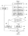
図2は、本実施形態における渦電流探傷方法の手順を表すフローチャートである。 FIG. 2 is a flowchart showing the procedure of the eddy current flaw detection method according to this embodiment.
まず、渦電流探傷プローブ1を被検査体5の検査位置に配置し(ステップ100)、プローブ1の励磁コイル3に励磁信号を印加して、被検査体5に渦電流を誘起する(ステップ110)。そして、渦電流の変化(若しくはそれに伴う磁束密度の変化)をプローブ1の検出コイル4a,4bで検出し、検出信号SA,SBを取得する(ステップ120)。
First, the eddy current
制御装置2の差分演算部8は、検出信号SAと検出信号SBとの差分を演算して差分信号SCを生成する(ステップ130)。制御装置2の比較判定部9は、検出コイル4aの検出信号の絶対値|SA|及び検出コイル4bの検出信号の絶対値|SB|のうちの大きいほうの絶対値を差分信号の絶対値|SC|と比較する(ステップ140)。詳細には、例えば検出信号の絶対値|SA|が検出信号の絶対値|SB|以上であれば、検出信号の絶対値|SA|が差分信号の絶対値|SC|以下であるかどうかを判定する。一方、例えば検出信号の絶対値|SA|が検出信号の絶対値|SB|未満であれば、検出信号の絶対値|SB|が差分信号の絶対値|SC|以下であるかどうかを判定する。
The
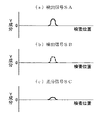
具体例をあげて説明する。例えば図3で示すように被検査体5のきず部分をプローブ1で走査した場合は、図4(a)及び図4(b)で示すような検出信号SA,SBが得られ、図4(c)で示すような差分信号SCが得られる。この場合、検出信号の絶対値|SA|が検出信号の絶対値|SB|より大きいから、検出信号の絶対値|SA|が差分信号の絶対値|SC|以下であるかどうかを判定する。そして、検出信号の絶対値|SA|が差分信号の絶対値|SC|以下であるから、ステップ140の判定が満たされ、ステップ150に移る。ステップ150では、検出信号SA,SBがきず信号である、すなわち、きず有りと判定する。
A specific example will be described. For example, as shown in FIG. 3, when the flaw portion of the
また、例えば図5で示すようにプローブ1と被検査体5の表面との距離が変化した場合は、図6(a)及び図6(b)で示すような検出信号SA,SBが得られ、図6(c)で示すような差分信号SCが得られる。この場合、検出信号の絶対値|SA|が検出信号の絶対値|SB|より大きいから、検出信号の絶対値|SA|が差分信号の絶対値|SC|以下であるかどうかを判定する。そして、検出信号の絶対値|SA|が差分信号の絶対値|SC|未満であるから、ステップ140の判定が満たされず、ステップ160に移る。ステップ160では、検出信号SA,SBがリフトオフ信号である、すなわち、きず無しと判定する。
For example, when the distance between the
そして、例えば被検査体5に検査すべき他の位置があれば、ステップ170の判定が満たされず、次の検査位置にプローブ1を移動し(ステップ180)、上述したステップ110〜140とステップ150又は160の手順を繰り返す。一方、被検査体5に検査すべき他の位置がなければ、ステップ170の判定が満たされて、検査終了となる。
For example, if there is another position on the
以上のように本実施形態においては、きず信号とリフトオフ信号を識別でき、きずの有無、すなわち被検査体5が健全かどうかを評価することができる。
As described above, in the present embodiment, the flaw signal and the lift-off signal can be identified, and it is possible to evaluate the presence or absence of flaws, that is, whether the inspected
なお、上記一実施形態において、渦電流探傷プローブ1は、1組の励磁コイル3及び検出コイル4a,4b(すなわち、3つのコイル)を備えた場合を例にとって説明したが、本発明の趣旨及び技術思想を逸脱しない範囲内で変形が可能である。すなわち、例えば図7で示す変形例のように、渦電流探傷プローブ1Aは、2組以上の励磁コイル3及び検出コイル4a,4b(すなわち、5つ以上のコイル)を備えていてもよく、励磁コイル3及び検出コイル4a,4bの組合せを順次切替えるようにしてもよい。なお、本変形例では、励磁コイル3と検出コイル4aの並び方向(図中左右方向)と励磁コイル3と検出コイル4bの並び方向(図中上下方向)が直交する場合(言い換えれば複数のコイルを正方配列する場合)を例にとって示しているが、これに限られない。すなわち、例えば、複数のコイルを千鳥配列してもよい。
In the above-described embodiment, the eddy current
また、上記一実施形態においては、制御装置2の差分演算部8が、検出コイル4aの検出信号SAと検出コイル4bの検出信号SBとの差分を演算して差分信号SCを生成し、制御装置2の比較判定部9が、検出コイル4aの検出信号の絶対値|SA|及び検出コイル4bの検出信号の絶対値|SB|のうちの大きいほうの絶対値を差分信号の絶対値|SC|と比較することにより、きずの有無を判定する場合を例にとって説明したが、本発明の趣旨及び技術思想を逸脱しない範囲内で変形が可能である。すなわち、例えば、検査者が、検出コイル4aの検出信号SAと検出コイル4bの検出信号SBとの差分を演算して差分信号SCを生成し、検出コイル4aの検出信号の絶対値|SA|及び検出コイル4bの検出信号の絶対値|SB|のうちの大きいほうの絶対値を差分信号の絶対値|SC|と比較することにより、きずの有無を判定してもよい。このような場合も、上記同様の効果を得ることができる。
In the above embodiment, the
1,1A 渦電流探傷プローブ
2 制御装置
3 励磁コイル
4a,4b 検出コイル
8 差分演算部
9 比較判定部
11 表示部
DESCRIPTION OF
Claims (3)
前記第1検出コイルの検出信号と前記第2検出コイルの検出信号との差分を演算して差分信号を生成し、
前記第1検出コイルの検出信号の絶対値及び前記第2検出コイルの検出信号の絶対値のうちの大きいほうの絶対値を前記差分信号の絶対値と比較して、前記差分信号の絶対値より小さい場合にきず有りと判定し、前記差分信号の絶対値より大きい場合にきず無しと判定することを特徴とする渦電流探傷方法。 Excitation coil, a first detection coil disposed in a first arrangement direction with respect to the excitation coil, and the placed in a second arrangement direction intersecting with the first arrangement direction with respect to the exciting coil In an eddy current testing method using an eddy current testing probe having two detection coils,
Calculating a difference between the detection signal of the first detection coil and the detection signal of the second detection coil to generate a difference signal;
The larger absolute value of the absolute value of the detection signal of the first detection coil and the absolute value of the detection signal of the second detection coil is compared with the absolute value of the differential signal, and the absolute value of the differential signal is An eddy current flaw detection method characterized in that it is determined that there is a flaw when it is small and that there is no flaw when it is larger than the absolute value of the difference signal.
前記第1検出コイルの検出信号と前記第2検出コイルの検出信号との差分を演算して差分信号を生成する差分演算部と、
前記第1検出コイルの検出信号の絶対値及び前記第2検出コイルの検出信号の絶対値のうちの大きいほうの絶対値を前記差分信号の絶対値と比較することにより、きずの有無を判定する比較判定部とを備え、
前記比較判定部は、前記第1検出コイルの検出信号の絶対値及び前記第2検出コイルの検出信号の絶対値のうちの大きいほうの絶対値が前記差分信号の絶対値より小さい場合にきず有りと判定し、前記差分信号の絶対値より大きい場合にきず無しと判定することを特徴とする渦電流探傷装置。 Excitation coil, a first detection coil disposed in a first arrangement direction with respect to the excitation coil, and the placed in a second arrangement direction intersecting with the first arrangement direction with respect to the exciting coil In an eddy current flaw detector provided with an eddy current flaw probe having two detection coils,
A difference calculation unit that calculates a difference between a detection signal of the first detection coil and a detection signal of the second detection coil to generate a difference signal;
The presence / absence of a flaw is determined by comparing the absolute value of the absolute value of the detection signal of the first detection coil and the absolute value of the detection signal of the second detection coil with the absolute value of the difference signal. A comparison judgment unit,
The comparison / determination unit has a flaw when the larger absolute value of the absolute value of the detection signal of the first detection coil and the absolute value of the detection signal of the second detection coil is smaller than the absolute value of the difference signal. The eddy current flaw detector is characterized in that it is determined that there is no flaw when it is larger than the absolute value of the difference signal.
前記比較判定部の判定結果を表示する表示部を備えたことを特徴とする渦電流探傷装置。 The eddy current flaw detector according to claim 2,
An eddy current flaw detector comprising a display unit for displaying a determination result of the comparison determination unit.
Priority Applications (1)
| Application Number | Priority Date | Filing Date | Title |
|---|---|---|---|
| JP2014072769A JP6170005B2 (en) | 2014-03-31 | 2014-03-31 | Eddy current flaw detection method and eddy current flaw detection apparatus |
Applications Claiming Priority (1)
| Application Number | Priority Date | Filing Date | Title |
|---|---|---|---|
| JP2014072769A JP6170005B2 (en) | 2014-03-31 | 2014-03-31 | Eddy current flaw detection method and eddy current flaw detection apparatus |
Publications (3)
| Publication Number | Publication Date |
|---|---|
| JP2015194419A JP2015194419A (en) | 2015-11-05 |
| JP2015194419A5 JP2015194419A5 (en) | 2016-09-15 |
| JP6170005B2 true JP6170005B2 (en) | 2017-07-26 |
Family
ID=54433577
Family Applications (1)
| Application Number | Title | Priority Date | Filing Date |
|---|---|---|---|
| JP2014072769A Active JP6170005B2 (en) | 2014-03-31 | 2014-03-31 | Eddy current flaw detection method and eddy current flaw detection apparatus |
Country Status (1)
| Country | Link |
|---|---|
| JP (1) | JP6170005B2 (en) |
Families Citing this family (1)
| Publication number | Priority date | Publication date | Assignee | Title |
|---|---|---|---|---|
| JP6751645B2 (en) * | 2016-10-20 | 2020-09-09 | 日立Geニュークリア・エナジー株式会社 | Eddy current flaw detection system and eddy current flaw detection method |
Family Cites Families (7)
| Publication number | Priority date | Publication date | Assignee | Title |
|---|---|---|---|---|
| FR2753534B1 (en) * | 1996-09-13 | 1999-04-23 | Intercontrole Sa | EDGE CURRENT PROBE FOR NON-DESTRUCTIVE INSPECTION OF ELECTRICALLY CONDUCTIVE PARTS |
| TR200002716A2 (en) * | 1999-09-22 | 2001-04-20 | General Electric Company | Induction current setting size |
| JP2004028897A (en) * | 2002-06-27 | 2004-01-29 | Osaka Gas Co Ltd | Eddy-current flaw detection apparatus |
| JP4311416B2 (en) * | 2006-06-30 | 2009-08-12 | 株式会社日立製作所 | Surface defect length evaluation method by eddy current testing |
| JP4902448B2 (en) * | 2007-07-10 | 2012-03-21 | 株式会社日立製作所 | Defect identification method and defect identification apparatus |
| US20130249540A1 (en) * | 2012-03-22 | 2013-09-26 | Olympus Ndt Inc. | Eddy current array probe and method for lift-off compensation during operation without known lift references |
| JP5710536B2 (en) * | 2012-03-29 | 2015-04-30 | 日立Geニュークリア・エナジー株式会社 | Calibration check method for eddy current flaw detector and eddy current flaw detector |
-
2014
- 2014-03-31 JP JP2014072769A patent/JP6170005B2/en active Active
Also Published As
| Publication number | Publication date |
|---|---|
| JP2015194419A (en) | 2015-11-05 |
Similar Documents
| Publication | Publication Date | Title |
|---|---|---|
| JP4829883B2 (en) | Method and apparatus for non-destructive inspection of tubes | |
| JP4863127B2 (en) | Magnetic flaw detection method and magnetic flaw detection apparatus | |
| JP5017038B2 (en) | Eddy current inspection apparatus and eddy current inspection method | |
| JP5946086B2 (en) | Eddy current inspection device, eddy current inspection probe, and eddy current inspection method | |
| WO2014142306A1 (en) | Eddy current flaw detection device, eddy current flaw detection method, and eddy current flaw detection program | |
| JP6083613B2 (en) | Magnetic nondestructive inspection equipment | |
| JP2011133268A (en) | Flaw detection device and method | |
| JP2006177952A (en) | Eddy current probe, inspecting system and inspecting method | |
| JP4766472B1 (en) | Nondestructive inspection apparatus and nondestructive inspection method | |
| JP6209119B2 (en) | Flaw detection method and flaw detection system | |
| WO2013125462A1 (en) | Eddy-current inspection method and device | |
| JP6170005B2 (en) | Eddy current flaw detection method and eddy current flaw detection apparatus | |
| JP2020071125A (en) | Method and device for determining defect, method for manufacturing steel plate, method for learning defect determination model, and defect determination model | |
| US10775346B2 (en) | Virtual channels for eddy current array probes | |
| JP6551885B2 (en) | Nondestructive inspection device and nondestructive inspection method | |
| JP2011069623A (en) | Eddy current flaw detection method | |
| JP2007121050A (en) | Flaw detector | |
| JP6288640B2 (en) | Eddy current flaw detection probe, eddy current flaw detection apparatus, and eddy current flaw detection method | |
| JP6058436B2 (en) | Eddy current flaw detector and eddy current flaw detection method | |
| JP5611863B2 (en) | Eddy current flaw detector, method, and program | |
| JP2016180701A5 (en) | ||
| JP6776676B2 (en) | Signal processing device and signal processing method | |
| JP2016080596A (en) | Eddy current flaw detection probe | |
| Deng et al. | Magneto-optic imaging for aircraft skins inspection: a probability of detection study of simulated and experimental image data | |
| JP2015105926A (en) | Eddy-current flaw detection device and eddy-current flaw detection method |
Legal Events
| Date | Code | Title | Description |
|---|---|---|---|
| A521 | Written amendment |
Free format text: JAPANESE INTERMEDIATE CODE: A523 Effective date: 20160727 |
|
| A621 | Written request for application examination |
Free format text: JAPANESE INTERMEDIATE CODE: A621 Effective date: 20160727 |
|
| A977 | Report on retrieval |
Free format text: JAPANESE INTERMEDIATE CODE: A971007 Effective date: 20170613 |
|
| TRDD | Decision of grant or rejection written | ||
| A01 | Written decision to grant a patent or to grant a registration (utility model) |
Free format text: JAPANESE INTERMEDIATE CODE: A01 Effective date: 20170620 |
|
| A61 | First payment of annual fees (during grant procedure) |
Free format text: JAPANESE INTERMEDIATE CODE: A61 Effective date: 20170629 |
|
| R150 | Certificate of patent or registration of utility model |
Ref document number: 6170005 Country of ref document: JP Free format text: JAPANESE INTERMEDIATE CODE: R150 |