JP6169971B2 - Digital sound system - Google Patents
Digital sound system Download PDFInfo
- Publication number
- JP6169971B2 JP6169971B2 JP2013540824A JP2013540824A JP6169971B2 JP 6169971 B2 JP6169971 B2 JP 6169971B2 JP 2013540824 A JP2013540824 A JP 2013540824A JP 2013540824 A JP2013540824 A JP 2013540824A JP 6169971 B2 JP6169971 B2 JP 6169971B2
- Authority
- JP
- Japan
- Prior art keywords
- digital
- parallel
- signal
- digital signal
- digital signals
- Prior art date
- Legal status (The legal status is an assumption and is not a legal conclusion. Google has not performed a legal analysis and makes no representation as to the accuracy of the status listed.)
- Expired - Fee Related
Links
Images


Classifications
-
- H—ELECTRICITY
- H03—ELECTRONIC CIRCUITRY
- H03F—AMPLIFIERS
- H03F3/00—Amplifiers with only discharge tubes or only semiconductor devices as amplifying elements
- H03F3/20—Power amplifiers, e.g. Class B amplifiers, Class C amplifiers
- H03F3/21—Power amplifiers, e.g. Class B amplifiers, Class C amplifiers with semiconductor devices only
- H03F3/217—Class D power amplifiers; Switching amplifiers
- H03F3/2175—Class D power amplifiers; Switching amplifiers using analogue-digital or digital-analogue conversion
-
- G—PHYSICS
- G06—COMPUTING; CALCULATING OR COUNTING
- G06F—ELECTRIC DIGITAL DATA PROCESSING
- G06F16/00—Information retrieval; Database structures therefor; File system structures therefor
- G06F16/60—Information retrieval; Database structures therefor; File system structures therefor of audio data
-
- H—ELECTRICITY
- H04—ELECTRIC COMMUNICATION TECHNIQUE
- H04H—BROADCAST COMMUNICATION
- H04H20/00—Arrangements for broadcast or for distribution combined with broadcast
- H04H20/86—Arrangements characterised by the broadcast information itself
- H04H20/88—Stereophonic broadcast systems
-
- H—ELECTRICITY
- H04—ELECTRIC COMMUNICATION TECHNIQUE
- H04R—LOUDSPEAKERS, MICROPHONES, GRAMOPHONE PICK-UPS OR LIKE ACOUSTIC ELECTROMECHANICAL TRANSDUCERS; DEAF-AID SETS; PUBLIC ADDRESS SYSTEMS
- H04R1/00—Details of transducers, loudspeakers or microphones
- H04R1/005—Details of transducers, loudspeakers or microphones using digitally weighted transducing elements
-
- H—ELECTRICITY
- H04—ELECTRIC COMMUNICATION TECHNIQUE
- H04R—LOUDSPEAKERS, MICROPHONES, GRAMOPHONE PICK-UPS OR LIKE ACOUSTIC ELECTROMECHANICAL TRANSDUCERS; DEAF-AID SETS; PUBLIC ADDRESS SYSTEMS
- H04R27/00—Public address systems
-
- H—ELECTRICITY
- H04—ELECTRIC COMMUNICATION TECHNIQUE
- H04R—LOUDSPEAKERS, MICROPHONES, GRAMOPHONE PICK-UPS OR LIKE ACOUSTIC ELECTROMECHANICAL TRANSDUCERS; DEAF-AID SETS; PUBLIC ADDRESS SYSTEMS
- H04R3/00—Circuits for transducers, loudspeakers or microphones
-
- H—ELECTRICITY
- H04—ELECTRIC COMMUNICATION TECHNIQUE
- H04R—LOUDSPEAKERS, MICROPHONES, GRAMOPHONE PICK-UPS OR LIKE ACOUSTIC ELECTROMECHANICAL TRANSDUCERS; DEAF-AID SETS; PUBLIC ADDRESS SYSTEMS
- H04R9/00—Transducers of moving-coil, moving-strip, or moving-wire type
- H04R9/06—Loudspeakers
- H04R9/063—Loudspeakers using a plurality of acoustic drivers
-
- H—ELECTRICITY
- H03—ELECTRONIC CIRCUITRY
- H03F—AMPLIFIERS
- H03F2200/00—Indexing scheme relating to amplifiers
- H03F2200/331—Sigma delta modulation being used in an amplifying circuit
-
- H—ELECTRICITY
- H04—ELECTRIC COMMUNICATION TECHNIQUE
- H04R—LOUDSPEAKERS, MICROPHONES, GRAMOPHONE PICK-UPS OR LIKE ACOUSTIC ELECTROMECHANICAL TRANSDUCERS; DEAF-AID SETS; PUBLIC ADDRESS SYSTEMS
- H04R2209/00—Details of transducers of the moving-coil, moving-strip, or moving-wire type covered by H04R9/00 but not provided for in any of its subgroups
- H04R2209/026—Transducers having separately controllable opposing diaphragms, e.g. for ring-tone and voice
-
- H—ELECTRICITY
- H04—ELECTRIC COMMUNICATION TECHNIQUE
- H04R—LOUDSPEAKERS, MICROPHONES, GRAMOPHONE PICK-UPS OR LIKE ACOUSTIC ELECTROMECHANICAL TRANSDUCERS; DEAF-AID SETS; PUBLIC ADDRESS SYSTEMS
- H04R2209/00—Details of transducers of the moving-coil, moving-strip, or moving-wire type covered by H04R9/00 but not provided for in any of its subgroups
- H04R2209/041—Voice coil arrangements comprising more than one voice coil unit on the same bobbin
-
- H—ELECTRICITY
- H04—ELECTRIC COMMUNICATION TECHNIQUE
- H04R—LOUDSPEAKERS, MICROPHONES, GRAMOPHONE PICK-UPS OR LIKE ACOUSTIC ELECTROMECHANICAL TRANSDUCERS; DEAF-AID SETS; PUBLIC ADDRESS SYSTEMS
- H04R2460/00—Details of hearing devices, i.e. of ear- or headphones covered by H04R1/10 or H04R5/033 but not provided for in any of their subgroups, or of hearing aids covered by H04R25/00 but not provided for in any of its subgroups
- H04R2460/03—Aspects of the reduction of energy consumption in hearing devices
Description
本発明は、デジタル信号をアナログ音声に直接変換するデジタルスピーカー装置を使ったデジタル音響システム及びそのアプリケーションなどに関する。 The present invention relates to a digital sound system using a digital speaker device that directly converts a digital signal into analog sound, an application thereof, and the like.
デジタル信号をアナログ音声に直接変換するデジタルスピーカー技術が提案されている(例えば、特許文献1参照。)。 A digital speaker technology that directly converts a digital signal into analog audio has been proposed (see, for example, Patent Document 1).
特許文献1のFig. 22には、X(L)およびY(R)の二つのデジタル音声信号を入力とし、ΔΣ変調器とミスマッチシェーピングフィルター回路により複数のデジタル信号を出力する回路と、前記複数のデジタル信号により駆動される複数のスピーカーもしくは複数の駆動素子とにより、アナログ音声を直接変換する方法が示されている。 In FIG. 22 of Patent Document 1, two digital audio signals X (L) and Y (R) are input, and a circuit that outputs a plurality of digital signals by a ΔΣ modulator and a mismatch shaping filter circuit, A method of directly converting analog sound by a plurality of speakers or a plurality of driving elements driven by a digital signal is shown.
このような、デジタル信号をアナログ音声に直接変換するデジタルスピーカー技術を用いたデジタルスピーカー装置は、アナログ電気信号により駆動されていたアナログスピーカー装置に比べて、消費電力が小さいという特徴がある。また、これに加えて、このようなデジタルスピーカー装置は、複数のスピーカー素子もしくは複数の駆動素子(コイル等)を使うことから、従来の一つのスピーカー素子もしくは単一の駆動素子を使ったスピーカーに比べて、大きな音を出すことが可能である。 Such a digital speaker device using a digital speaker technology that directly converts a digital signal into an analog sound has a feature that it consumes less power than an analog speaker device driven by an analog electric signal. In addition, since such a digital speaker device uses a plurality of speaker elements or a plurality of driving elements (coils, etc.), the conventional speaker apparatus uses a single speaker element or a single driving element. In comparison, it is possible to produce a loud sound.
しかしながら、デジタルスピーカー装置ではPCM音源からのデジタル信号をΔΣ変調器とミスマッチシェーピングフィルター回路により複数のデジタル信号を出力する回路が必須であり、これらの回路をLSI上に実装する為には微細デジタルプロセスを使う必要がある。 However, a digital speaker device requires a circuit that outputs a digital signal from a PCM sound source using a delta-sigma modulator and a mismatch shaping filter circuit. To implement these circuits on an LSI, a fine digital process is required. It is necessary to use.
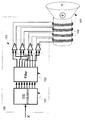
図1に、従来のデジタルスピーカー装置を使ったデジタル音響システムの代表的な例として、デジタルスピーカー装置のシステムの従来例を示す。この従来例のデジタルスピーカー装置のシステムは、ΔΣ変調器と後置フィルター回路により複数のデジタル信号を出力する回路と複数のスピーカー駆動素子からなる。1ビットのデジタル入力信号(110)はΔΣ変調器(101)に入力される、ΔΣ変調器(101)でnビットの複数のデジタル信号(111)に変換する。nビットの複数のデジタル信号は後置フィルター(102)でミスマッチシェーピングされたm個のデジタル信号(112)に変換される。m個のデジタル信号は、スピーカー駆動回路(103)に入力されs個の駆動素子(104)を駆動してアナログ音声を振動膜(105)により直接変換する。前記ΔΣ変調器(101)と後置フィルター(102)とスピーカー駆動回路(103)とがデジタルスピーカー装置(100)の構成要素である。 FIG. 1 shows a conventional example of a digital speaker device system as a typical example of a digital sound system using a conventional digital speaker device. This conventional digital speaker device system includes a circuit for outputting a plurality of digital signals by a ΔΣ modulator and a post filter circuit, and a plurality of speaker driving elements. The 1-bit digital input signal (110) is input to the ΔΣ modulator (101), and is converted into a plurality of n-bit digital signals (111) by the ΔΣ modulator (101). A plurality of n-bit digital signals are converted into m number of digital signals (112) mismatch-shaped by a post filter (102). The m digital signals are input to the speaker drive circuit (103) and drive the s drive elements (104) to directly convert the analog sound by the vibrating membrane (105). The ΔΣ modulator (101), the post filter (102), and the speaker driving circuit (103) are components of the digital speaker device (100).
従来例では、ΔΣ変調器(101)と後置フィルター(102)とスピーカー駆動回路(103)とがスピーカー毎に必要になるので、多数のスピーカーが用いられる映画館や劇場にデジタルスピーカー装置を使う場合に微細デジタルプロセスのLSIを多数必要とする課題がある。 In the conventional example, since a ΔΣ modulator (101), a post filter (102), and a speaker drive circuit (103) are required for each speaker, a digital speaker device is used in a movie theater or a theater where a large number of speakers are used. In some cases, there is a problem of requiring a large number of fine digital process LSIs.
本発明は、デジタル信号により駆動される複数のスピーカー(コイル)によりアナログ音声を直接変換するデジタルスピーカー装置に最適なデジタル音響システムを提案することを目的とする。 An object of the present invention is to propose a digital sound system that is most suitable for a digital speaker device that directly converts analog sound by a plurality of speakers (coils) driven by digital signals.
本発明の一実施形態として、デジタル入力信号を変調しnビットのデジタル信号を出力するΔΣ変調器と、前記ΔΣ変調器に接続され前記nビットのデジタル信号をミスマッチシェーピングしm個のデジタル信号に変換する後置フィルターと、前記後置フィルターが変換したm個のデジタル信号をシリアル伝送されるデジタル信号に変換するパラレル・シリアル変換器と、前記パラレル・シリアル変換器により変換されたデジタル信号をm個のデジタル信号に変換し復元するシリアル・パラレル変換器と、前記シリアル・パラレル変換器により復元されたm個のデジタル信号を受け取り、s個の駆動素子を駆動してアナログ音声に変換する駆動回路とを有するデジタル音響システムを提供する。 As one embodiment of the present invention, a ΔΣ modulator that modulates a digital input signal and outputs an n-bit digital signal, and is connected to the ΔΣ modulator to mismatch-shape the n-bit digital signal into m digital signals. A post-filter for conversion, a parallel-serial converter for converting m digital signals converted by the post-filter into digital signals to be serially transmitted, and m for converting the digital signal converted by the parallel-serial converter A serial / parallel converter that converts and restores digital signals and a drive circuit that receives m digital signals restored by the serial / parallel converter and drives s drive elements to convert them into analog audio A digital sound system is provided.
本発明の一実施形態として、デジタル入力信号をm個のデジタル信号に変換するプロセッサと、前記プロセッサが変換したm個のデジタル信号をシリアル伝送されるデジタル信号に変換するパラレル・シリアル変換器と、前記パラレル・シリアル変換器により変換されたデジタル信号をm個のデジタル信号に変換し復元するシリアル・パラレル変換器と、 前記シリアル・パラレル変換器により復元されたm個のデジタル信号を受け取り、s個の駆動素子を駆動してアナログ音声に変換する駆動回路とを有し、前記プロセッサは、前記プロセッサを、デジタル入力信号を変調しnビットのデジタル信号を出力するΔΣ変調器と、前記ΔΣ変調器に接続され前記nビットのデジタル信号をミスマッチシェーピングしm個のデジタル信号に変換する後置フィルターとして、動作させるためのプログラムにより、制御されることを特徴とするデジタル音響システムを提供する。 As one embodiment of the present invention, a processor that converts a digital input signal into m digital signals, a parallel-serial converter that converts m digital signals converted by the processor into digital signals that are serially transmitted, A serial / parallel converter that converts the digital signal converted by the parallel / serial converter into m digital signals and restores the digital signal, and receives m digital signals restored by the serial / parallel converter, and s A driving circuit for converting the driving element to analog sound, and the processor modulates the digital input signal and outputs an n-bit digital signal, and the ΔΣ modulator. A post filter connected to the N-bit and mismatch-shaped to convert the n-bit digital signal into m digital signals As, by the program for operating, providing a digital acoustic system being controlled.
本発明によれば、デジタルスピーカーの特性として、低消費電力特性を損なうことなく、多数のスピーカーを使う用途である映画館や劇場にデジタルスピーカー装置を使う場合でも、従来のデジタル音響システムに比べ単純な装置の組み合わせでデジタル音響システムを構築することが出来るため、デジタル音響システムのコストの低減が可能になる。 According to the present invention, as a characteristic of a digital speaker, even when a digital speaker device is used in a movie theater or a theater where many speakers are used without impairing the low power consumption characteristic, it is simpler than a conventional digital sound system. Since a digital sound system can be constructed by combining various devices, the cost of the digital sound system can be reduced.
(第1の実施形態)
図2に本発明の第1の実施形態に係る、デジタルスピーカー装置を使ったデジタル音響システムの構成を示す。本実施形態に係るデジタルスピーカー装置は、デジタル信号から複数のデジタル信号を出力する装置と、この装置が出力する複数のデジタル信号により複数のスピーカー駆動素子を駆動する駆動装置で構成される。本実施形態の特徴の一つは、複数のデジタル信号を出力する装置とスピーカー駆動素子を駆動する駆動装置の間をパラレル・シリアル変換装置とシリアル・パラレル変換装置により接続する点である。(First embodiment)
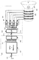
FIG. 2 shows a configuration of a digital sound system using a digital speaker device according to the first embodiment of the present invention. The digital speaker device according to the present embodiment includes a device that outputs a plurality of digital signals from a digital signal, and a driving device that drives a plurality of speaker driving elements by the plurality of digital signals output from the device. One of the features of this embodiment is that a parallel / serial conversion device and a serial / parallel conversion device connect between a device that outputs a plurality of digital signals and a drive device that drives a speaker drive element.
図2を参照すると、デジタル入力信号(210)はΔΣ変調器(201)に入力され、ΔΣ変調器(201)でnビットの複数のデジタル信号(211)に変換される。nビットの複数のデジタル信号は後置フィルター(202)でミスマッチシェーピングされたm個のデジタル信号(212)に変換される。m個のデジタル信号は、パラレル・シリアル変換器(203)でシリアル伝送されるデジタル信号(213)に変換され、シリアル・パラレル変換器(204)でm個のデジタル信号(214)に戻される。シリアル伝送されるデジタル信号(213)のビット数としては例えば1を挙げることができるが、1に限定はされない。m個のデジタル信号(214)を受け取ったスピーカー駆動回路(205)はs個の駆動素子(206)を駆動してアナログ音声を振動膜(207)により直接変換する。ここで、ΔΣ変調器(201)と後置フィルター(202)とパラレル・シリアル変換器(203)とがデジタル信号から複数のデジタル信号を出力する装置(200)を構成している。また、シリアル・パラレル変換器(204)とスピーカー駆動回路(205)とがスピーカー駆動素子を駆動する駆動装置(220)を構成している。 Referring to FIG. 2, a digital input signal (210) is input to a ΔΣ modulator (201), and converted into a plurality of n-bit digital signals (211) by the ΔΣ modulator (201). The plurality of n-bit digital signals are converted into m digital signals (212) that have been mismatch-shaped by the post filter (202). The m digital signals are converted into digital signals (213) that are serially transmitted by the parallel / serial converter (203), and returned to m digital signals (214) by the serial / parallel converter (204). An example of the number of bits of the digital signal (213) to be serially transmitted is one, but is not limited to one. Upon receiving the m digital signals (214), the speaker drive circuit (205) drives the s drive elements (206) to directly convert the analog sound by the diaphragm (207). Here, the ΔΣ modulator (201), the post filter (202), and the parallel / serial converter (203) constitute an apparatus (200) for outputting a plurality of digital signals from the digital signals. The serial / parallel converter (204) and the speaker drive circuit (205) constitute a drive device (220) for driving the speaker drive element.
本実施形態のように、入力されたデジタル信号から複数のデジタル信号を出力する装置と、スピーカー駆動素子を駆動する駆動装置をシリアル信号で結ぶことが可能になると、デジタル信号から複数のデジタル信号を出力する装置に対して複数のスピーカー駆動素子を駆動する駆動装置をシリアル信号で接続する事が可能になる。したがって、多数のスピーカーを使う例えば映画館や劇場にデジタルスピーカー装置を使う場合でも、従来のデジタル音響システムに比べ単純な装置の組み合わせでデジタル音響システムを構築することが出来る。これにより、デジタル音響システムのコストの低減が可能になる。 When a device that outputs a plurality of digital signals from an input digital signal and a driving device that drives a speaker driving element can be connected with a serial signal as in this embodiment, a plurality of digital signals are converted from the digital signal. It is possible to connect a driving device for driving a plurality of speaker driving elements to a device for outputting with a serial signal. Therefore, even when a digital speaker device is used in, for example, a movie theater or a theater that uses a large number of speakers, a digital sound system can be constructed with a combination of simple devices as compared with a conventional digital sound system. Thereby, the cost of the digital acoustic system can be reduced.
図2に示す第1の実施形態に係る構成の一例として、デジタル信号から複数のデジタル信号を出力する装置と、スピーカー駆動素子を駆動する駆動装置を電気的にシリアル信号で結ぶ例が示されている。しかし、本実施形態は、この例に限定されることはなく、シリアル信号を無線装置で接続したり、光信号で接続したりするなど、電磁誘導や電界の強度により伝送する構成も本実施形態に含まれる。また,図2に示したパラレル・シリアル変換器(203)で、パラレル信号(212)を、複数のシリアル信号に変換する実施例も含まれる。 As an example of the configuration according to the first embodiment shown in FIG. 2, there is shown an example in which a device that outputs a plurality of digital signals from a digital signal and a drive device that drives a speaker drive element are electrically connected by a serial signal. Yes. However, the present embodiment is not limited to this example, and a configuration in which serial signals are connected by a wireless device or connected by an optical signal, such as transmission by electromagnetic induction or electric field strength, is also used in the present embodiment. include. Further, the parallel-serial converter (203) shown in FIG. 2 includes an embodiment in which the parallel signal (212) is converted into a plurality of serial signals.
また、スピーカー駆動素子を駆動する駆動装置をデジタル信号から複数のデジタル信号を出力する装置に分けることで、それぞれの装置に最適なデバイステクノロジーを用いてLSI化を進めることが可能になる。これにより、システム全体のコストを低減することや、スピーカー駆動素子を駆動する駆動装置側の動作電圧を上げることができる。したがって、大音量を再生することもコストの増大を伴わずに容易に構成することが可能になる。 Further, by dividing the driving device for driving the speaker driving element into devices that output a plurality of digital signals from digital signals, it is possible to proceed to LSI using device technology that is optimal for each device. As a result, the cost of the entire system can be reduced, and the operating voltage on the drive device side that drives the speaker drive element can be increased. Therefore, reproducing a large volume can be easily configured without increasing the cost.
(第2の実施形態)
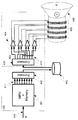
図3に、本発明の第3の実施形態に係る、複数のデジタル信号を出力する回路と複数のスピーカー駆動素子とを備えるデジタルスピーカー装置の構成を示す。デジタル入力信号(310)はマイクロコンピューター装置(301)に入力されミスマッチシェーピングされたm個のデジタル信号(311)に変換される。m個のデジタル信号は、パラレル・シリアル変換器(302)で1ビットのデジタル信号(312)に変換され、シリアル・パラレル変換器(303)でm個のデジタル信号(313)に戻される。m個のデジタル信号(214)を受け取ったスピーカー駆動回路(304)はs個の駆動素子(305)を駆動してアナログ音声を振動膜(306)により直接変換する。(Second Embodiment)
FIG. 3 shows a configuration of a digital speaker device including a circuit for outputting a plurality of digital signals and a plurality of speaker driving elements according to the third embodiment of the present invention. The digital input signal (310) is input to the microcomputer device (301) and converted to m number of digital signals (311) which have been mismatch shaped. The m digital signals are converted into a 1-bit digital signal (312) by the parallel / serial converter (302), and returned to the m digital signals (313) by the serial / parallel converter (303). Upon receiving m digital signals (214), the speaker drive circuit (304) drives the s drive elements (305) to directly convert the analog sound by the diaphragm (306).
ここで、マイクロコンピューター装置(301)とパラレル・シリアル変換器(302)が、デジタル信号から複数のデジタル信号を出力する装置(300)を構成し、シリアル・パラレル変換器(303)とスピーカー駆動回路(304)とが駆動装置(320)を構成している。駆動装置(320)において、スピーカー駆動素子が駆動される。マイクロコンピューター装置(301)は、プ
ロセッサを有し、プロセッサは、デジタル入力信号を変調しnビットのデジタル信号を出力するΔΣ変調器と、ΔΣ変調器に接続されnビットのデジタル信号をミスマッチシェーピングしm個のデジタル信号に変換する後置フィルターとして、動作させるためのプログラムにより、制御されるHere, the microcomputer device (301) and the parallel / serial converter (302) constitute a device (300) that outputs a plurality of digital signals from the digital signal, and the serial / parallel converter (303) and the speaker drive circuit. (304) constitutes the drive unit (320). In the driving device (320), the speaker driving element is driven. The microcomputer device (301) has a processor, which modulates a digital input signal and outputs an n-bit digital signal, and performs mismatch shaping of the n-bit digital signal connected to the ΔΣ modulator. Controlled by a program to operate as a post filter that converts to m digital signals
本実施形態のように、入力されたデジタル信号から複数のデジタル信号を出力する装置として、プロセッサを有するマイクロコンピューター装置を用いることで、第1の実施形態のΔΣ変調器と後置フィルターで行った事と同様のデジタル信号処理を、プログラムで処理することが可能になる。プログラムで処理することでΔΣ変調器の変調特性や後置フィルターでのフィルター特性をハードウェアの変更無しに更新し改良する事が可能になる。 As in this embodiment, as a device that outputs a plurality of digital signals from an input digital signal, a microcomputer device having a processor is used, and the ΔΣ modulator and the post filter of the first embodiment are used. Digital signal processing similar to that described above can be processed by a program. By processing with a program, it becomes possible to update and improve the modulation characteristics of the ΔΣ modulator and the filter characteristics of the post filter without changing the hardware.
(第3の実施形態)
図4に複数のデジタル信号を出力する回路と複数のスピーカー駆動素子からなるデジタルスピーカー装置のシステム形態の第3の実施形態を示す。デジタル入力信号(410)はマイクロコンピューター装置(401)に入力されミスマッチシェーピングされたm個のデジタル信号(411)に変換される。m個のデジタル信号は、フォーマット変換器(402)で記憶装置(312)に一度記録され、再度フォーマット変換器(403)でm個のデジタル信号(413)に戻される。なお、フォーマット変換器(402)の出力をパラレル・シリアル変換器によりシリアル伝送されるデジタル信号に変換し、記憶装置(312)にデジタル信号を記憶してもよい。また、記憶装置(312)から読み出されたデジタル信号は、シリアル・パラレル変換器に入力され、フォーマット変換器(403)に入力されてもよい。また、フォーマット変換器(402)がパラレル・シリアル変換器を含み、フォーマット変換器(403)がシリアル・パラレル変換器を含む構成でもよい。(Third embodiment)
FIG. 4 shows a third embodiment of a system form of a digital speaker device comprising a circuit for outputting a plurality of digital signals and a plurality of speaker driving elements. The digital input signal (410) is input to the microcomputer device (401) and converted to m number of digital signals (411) which have been mismatch shaped. The m digital signals are once recorded in the storage device (312) by the format converter (402), and returned to the m digital signals (413) by the format converter (403) again. The output of the format converter (402) may be converted into a digital signal that is serially transmitted by a parallel / serial converter, and the digital signal may be stored in the storage device (312). The digital signal read from the storage device (312) may be input to the serial / parallel converter and input to the format converter (403). Further, the format converter (402) may include a parallel / serial converter, and the format converter (403) may include a serial / parallel converter.
前記m個のデジタル信号(414)を受け取ったスピーカー駆動回路(404)はs個の駆動素子(405)を駆動してアナログ音声を振動膜(406)により直接変換する。ここで、マイクロコンピューター装置(401)とフォーマット変換器(402)とが、デジタル信号から複数のデジタル信号を出力する装置(400)を構成している。また、フォーマット変換器(403)とスピーカー駆動回路(404)とがスピーカー駆動素子を駆動する駆動装置(420)を構成している。 Upon receiving the m digital signals (414), the speaker driving circuit (404) drives the s driving elements (405) to directly convert the analog sound by the vibrating membrane (406). Here, the microcomputer device (401) and the format converter (402) constitute a device (400) that outputs a plurality of digital signals from digital signals. Further, the format converter (403) and the speaker drive circuit (404) constitute a drive device (420) for driving the speaker drive element.
第3の実施形態のようにデジタル信号から複数のデジタル信号を出力する装置と、スピーカー駆動素子を駆動する駆動装置を記憶装置で結ぶことが可能になると、音声再生の実時間処理が出来ない、例えば処理速度の遅いマイクロコンピューター装置を用いても、第1の実施形態のΔΣ変調器と後置フィルターで行った事と同様のデジタル信号処理をプログラムで処理することが可能になるので、従来のデジタル音響システムに比べ、より低消費電力のデジタル音響システムが可能になる。 When a device that outputs a plurality of digital signals from a digital signal and a drive device that drives a speaker drive element can be connected by a storage device as in the third embodiment, real-time processing of audio reproduction cannot be performed. For example, even if a microcomputer device having a low processing speed is used, it becomes possible to process digital signal processing similar to that performed by the ΔΣ modulator and the post filter of the first embodiment with a program. Compared with a digital sound system, a digital sound system with lower power consumption becomes possible.
また、デジタル信号処理をプログラムで処理した結果を複数回再生する場合には、記憶装置から事前に計算した結果を読みだすだけでよいので、再計算を行う必要がなくなるので、従来のデジタル音響システムに比べ、より低消費電力のデジタル音響システムが可能になる。 In addition, when reproducing the result of digital signal processing by a program multiple times, it is only necessary to read the result calculated in advance from the storage device, so there is no need to perform recalculation. Compared to this, a digital sound system with lower power consumption becomes possible.
また、フォーマッタ変換器(402)では、ミスマッチシェーピングされたm個のデジタル信号に対しロスレスデータ圧縮を行うことも可能である。フォーマット変換器(403)では、データの伸張を行い元のm個のデジタル信号を再生する。このようにデータを圧縮することで必要な記憶媒体の容量を大幅に低減することが可能となる。ここで、データの圧縮伸張方法には、演算量およびデータ圧縮率を勘案し選択することで記憶媒体およびハードウェア規模の最適を図ることも可能となる。 Further, the formatter converter (402) can perform lossless data compression on m digital signals subjected to mismatch shaping. The format converter (403) decompresses the data and reproduces the original m digital signals. By compressing the data in this way, it is possible to significantly reduce the required storage medium capacity. Here, it is possible to optimize the storage medium and the hardware scale by selecting the data compression / decompression method in consideration of the calculation amount and the data compression rate.
(第4の実施形態)
図5に複数のデジタル信号を出力する回路と複数のスピーカー駆動素子からなるデジタルスピーカー装置のシステム形態の第4の実施形態を示す。デジタル入力信号(510)はマイクロコンピューター装置(501)に入力されミスマッチシェーピングされたm個のデジタル信号(511)に変換される。m個のデジタル信号は、パラレル・シリアル変換器(502)で、シリアル伝送される例えば1ビットのデジタル信号(512)に、一旦変換され、再度シリアル・パラレル変換器(503)でm個のデジタル信号(513)に戻される。前記m個のデジタル信号(514)を受け取ったスピーカー駆動回路(504)はs個の駆動素子(505)を駆動してアナログ音声を振動膜(506)により直接変換する。ここで、マイクロコンピューター装置(501)とパラレル・シリアル変換器(502)とが、デジタル信号から複数のデジタル信号を出力する装置(500)を構成している。また、シリアル・パラレル変換器(503)とスピーカー駆動回路(504)とがスピーカー駆動素子を駆動する駆動装置(520)を構成している。更に駆動装置(520)はスピーカー駆動回路の個数や特性を記憶したID素子(521)を備え、そのID素子からの情報を、複数のデジタル信号を出力する装置(500)に伝える伝送手段(522)を設置する。伝送手段(522)は、マイクロコンピューター装置(501)にID素子(521)からの情報を伝送する。(Fourth embodiment)
FIG. 5 shows a fourth embodiment of a system form of a digital speaker device comprising a circuit for outputting a plurality of digital signals and a plurality of speaker driving elements. The digital input signal (510) is inputted to the microcomputer device (501) and converted into m number of digital signals (511) subjected to mismatch shaping. The m digital signals are once converted into, for example, a 1-bit digital signal (512) to be serially transmitted by the parallel / serial converter (502), and then again m digital signals are transmitted by the serial / parallel converter (503). Returned to signal (513). Upon receiving the m digital signals (514), the speaker driving circuit (504) drives the s driving elements (505) to directly convert the analog sound by the diaphragm (506). Here, the microcomputer device (501) and the parallel / serial converter (502) constitute a device (500) for outputting a plurality of digital signals from the digital signals. Further, the serial / parallel converter (503) and the speaker drive circuit (504) constitute a drive device (520) for driving the speaker drive element. Further, the driving device (520) includes an ID element (521) that stores the number and characteristics of speaker driving circuits, and transmission means (522) that transmits information from the ID element to a device (500) that outputs a plurality of digital signals. ). The transmission means (522) transmits information from the ID element (521) to the microcomputer device (501).
本実施形態のようにデジタル信号から複数のデジタル信号を出力する装置にマイクロコンピューター装置を用いることにより、第1の実施形態のΔΣ変調器と後置フィルターで行った事と同様のデジタル信号処理をプログラムで処理することが可能になる。さらに、駆動装置(520)の情報を利用することで、駆動回路の個数や特性に適合するデジタル信号
処理をプログラムにより対応することが可能になるので、異なる駆動装置を一つの複数のデジタル信号を出力する装置に接続することが可能になる。By using a microcomputer device as a device for outputting a plurality of digital signals from a digital signal as in this embodiment, digital signal processing similar to that performed by the ΔΣ modulator and post filter of the first embodiment is performed. It can be processed by a program. Furthermore, by using the information of the drive device (520), it becomes possible to handle digital signal processing that matches the number and characteristics of the drive circuit by a program, so that different drive devices can be used as one digital signal. It becomes possible to connect to an output device.
(第5の実施形態)
図6に複数のデジタル信号を出力する回路と複数のスピーカー駆動素子からなるデジタルスピーカー装置のシステム形態の第5の実施形態を示す。図4に示した第3の実施形態と同じように、あらかじめ複数のスピーカー駆動素子を駆動する信号をデジタル信号から複数のデジタル信号を出力する装置(600)により生成して保存メディア(記憶媒体)(613)に保存しておくことが可能である。これにより変換されたデータを、保存メディア(613)を使って流通させることが可能となる。このあらかじめ変換されたデータをネットワーク通じて直接顧客に配信したり、あらかじめ変換されたデータを保存メディア(記憶媒体)に記録し流通させたりすることにより、従来必要であったフォーマッタ変換器(602)を、再生する装置側で用意する必要がなくなり、デジタルスピーカー装置をより廉価に提供することが可能となる。(Fifth embodiment)
FIG. 6 shows a fifth embodiment of a system form of a digital speaker device comprising a circuit for outputting a plurality of digital signals and a plurality of speaker driving elements. Similar to the third embodiment shown in FIG. 4, a signal for driving a plurality of speaker driving elements is generated in advance by a device (600) that outputs a plurality of digital signals from a digital signal, and is stored as a storage medium (storage medium). (613) can be stored. Thus, the converted data can be distributed using the storage medium (613). This pre-converted data is distributed directly to customers via the network, or the pre-converted data is recorded on a storage medium (storage medium) and distributed, so that the formatter converter (602) that has been necessary in the past Can be provided at a lower cost, and the digital speaker device can be provided at a lower price.
保存メディア(記憶媒体)としては、光ディスク、メモリカードなどの媒体を挙げることができる。これらの媒体は、記憶装置に着脱することができるものであることが好ましい。したがって、これらの光ディスク、メモリカードは据え置き型や携帯型の再生装置としての駆動装置(620)に装着して再生を行ってもよい。また、ネットワークを通じて直接顧客に配信する場合には、ストリーム形式で配信を行ったり、顧客の有する保存メディア(記憶媒体)に配信したデータを一旦記録したりしてもよい。 Examples of the storage medium (storage medium) include media such as an optical disk and a memory card. These media are preferably detachable from the storage device. Therefore, these optical disks and memory cards may be played back by being mounted on a drive device (620) as a stationary or portable playback device. Further, when delivering directly to a customer via a network, the delivery may be performed in a stream format, or the data delivered to a storage medium (storage medium) possessed by the customer may be temporarily recorded.
また、あらかじめいくつかの駆動素子数に対応させたデータを生成し、記録することで駆動素子数の異なるデジタルスピーカシステムに対応させることも可能である。この方法は、特に記録媒体の記録密度が上がり単価が低い場合にはコストを低減できる有効な手段となる。 It is also possible to generate data corresponding to a number of drive elements in advance and record it so as to correspond to a digital speaker system having a different number of drive elements. This method is an effective means for reducing the cost especially when the recording density of the recording medium increases and the unit price is low.
また、複数のスピーカー駆動素子を駆動する信号をデジタル信号から複数のデジタル信号を出力する装置(600)からの出力は、デジタル変調されている為に、変調前のデジタル信号に戻すことが困難となる場合がある。したがって、装置(600)からの出力に、コピープロテクトされたに等しい効果を持たせることができる。さらにセキュリティ度を増す為に、前記記憶媒体に記録する際に暗号化を施したり、電子透かしデータを重畳したりすることも可能である。ΔΣ変調器(601)を用いているため,音楽信号等の信号帯域以外の帯域(通常信号帯域以上の周波数帯域)に、電子透かし信号を挿入することにより、最終的に音響信号に変換された際の音質の劣化を最小限に電子透かしを用いることが可能となる。暗号化や電子透かしデータの重畳は、例えばΔΣ変調器(601)、後置フィルター(602)またはパラレル・シリアル変換器(603)に実行させることができる。例えば、ΔΣ変調器(601)、後置フィルター(602)またはパラレル・シリアル変換器(603)に、暗号化や電子透かしデータの重畳のための装置を備えてもよい。また、そのような装置は、独立した装置であってもよい。 In addition, since the output from the device (600) that outputs a plurality of digital signals from a digital signal as a signal for driving a plurality of speaker driving elements is digitally modulated, it is difficult to return to a digital signal before modulation. There is a case. Therefore, the output from the apparatus (600) can have an effect equivalent to copy protection. In order to further increase the security level, it is possible to perform encryption or superimpose digital watermark data when recording on the storage medium. Since a ΔΣ modulator (601) is used, it is finally converted into an acoustic signal by inserting a digital watermark signal into a band other than the signal band of music signals, etc. (frequency band higher than the normal signal band). It is possible to use a digital watermark with minimal degradation of sound quality. Encryption and digital watermark data superimposition can be executed by, for example, the ΔΣ modulator (601), the post filter (602), or the parallel / serial converter (603). For example, the ΔΣ modulator (601), the post filter (602), or the parallel / serial converter (603) may be provided with a device for encryption or superimposition of digital watermark data. Such a device may be an independent device.
さらに、用いるコイル数を変更できるデータを記録媒体等に記録することにより、1通りのデータのみを記録することで、複数のコイル数に対応させることが可能となり、利便性を向上させることも可能である。 Furthermore, by recording data that can change the number of coils to be used on a recording medium, etc., it is possible to handle multiple coils by recording only one type of data, which can also improve convenience. It is.
(第6の実施形態)
実施形態1から5におけるΔΣ変調器にカスコード型ΔΣ変調器を用いることも可能である。図7にカスコード型ΔΣ変調器の内部量子化器に多ビットのものを用いた場合の実施形態を示す。カスコード型ΔΣ変調器(701)では、初段および2段目以降の複数の内部ΔΣ変調器が出力される。初段のn1ビットの複数のデジタル信号(711a)は後置フィルター(702a)でミスマッチシェーピングされたm1個のデジタル信号(712a)に変換される。2段目以降のnx出力(711b)には後置フィルタ(702b)で周波数特性を付加し、さらにミスマッチシェーピングされたmx個のデジタル信号(712b)に変換される。(Sixth embodiment)
It is also possible to use a cascode type ΔΣ modulator for the ΔΣ modulator in the first to fifth embodiments. FIG. 7 shows an embodiment when a multi-bit internal quantizer is used for a cascode ΔΣ modulator. The cascode ΔΣ modulator (701) outputs a plurality of internal ΔΣ modulators in the first stage and the second and subsequent stages. The plurality of n 1 -bit digital signals (711a) in the first stage are converted into m 1 digital signals (712a) that are mismatch-shaped by the post filter (702a). The n x output of the second and subsequent stages (711b) adds a frequency characteristic in a post filter (702b), is further converted to mismatch shaping been m x number of digital signals (712b).
m1+m2+…+mx個のデジタル信号は、パラレル・シリアル変換器(703)で1ビットのデジタル信号(713)に一旦変換され、再度シリアル・パラレル変換器(704)でm1+m2+…+mx個のデジタル信号(714)に戻される。前記m1+m2+…+mx個のデジタル信号(714)を受け取ったスピーカー駆動回路(705)はs個の駆動素子(706)を駆動してアナログ音声を振動膜(707)により直接変換する。ここで、カスコード型ΔΣ変調器(701)と後置フィルター(702a、b)とパラレル・シリアル変換器(703)とがデジタル信号から複数のデジタル信号を出力する装置(700)を構成している。また、シリアル・パラレル変換器(704)とスピーカー駆動回路(705)とがスピーカー駆動素子を駆動する駆動装置(720)を構成している。m 1 + m 2 +... + m x digital signals are once converted into a 1-bit digital signal (713) by the parallel-serial converter (703), and again m 1 + m by the serial-parallel converter (704). 2 + ... + m Returned to x digital signals (714). Upon receiving the m 1 + m 2 +... + M x digital signals (714), the speaker drive circuit (705) drives the s drive elements (706) to directly convert the analog sound by the diaphragm (707). To do. Here, the cascode type ΔΣ modulator (701), the post filters (702a, b), and the parallel-serial converter (703) constitute a device (700) that outputs a plurality of digital signals from the digital signals. . The serial / parallel converter (704) and the speaker drive circuit (705) constitute a drive device (720) for driving the speaker drive element.
カスケード型ΔΣDACと同様に、2段目以降の出力は1段目出力に含まれる雑音成分を打ち消す符号となっている。このため、駆動素子(606)がm1+m2…+mxよりも少ない場合は、後段のm2…mxを使用しないでも十分高精度な変換を行うことが可能である。Similar to the cascade type ΔΣ DAC, the output after the second stage is a code that cancels the noise component included in the first stage output. Therefore, when the driving element (606) is less than m 1 + m 2 ... + m x may be also without using subsequent m 2 ... m x performed sufficiently high accuracy conversion.
(第7の実施形態)
図8に、本発明の第7の実施形態に係る、複数のデジタル信号を出力する回路と複数のスピーカー駆動素子とを備えるデジタルスピーカー装置の構成を示す。デジタル入力信号(810)はデジタルシグナルプロセッサー装置(DSP)(801)に入力されミスマッチシェーピングされたm個のデジタル信号(811)に変換される。m個のデジタル信号(811)は、パラレル・シリアル変換器(802)でs個のデジタル信号(812)に変換され、シリアル・パラレル変換器(803)でm個のデジタル信号(813)に戻される。m個のデジタル信号(814)を受け取ったスピーカー駆動回路(804)はs個の駆動素子(805)を駆動してアナログ音声を振動膜(806)により直接変換する。(Seventh embodiment)
FIG. 8 shows a configuration of a digital speaker device including a circuit for outputting a plurality of digital signals and a plurality of speaker driving elements according to the seventh embodiment of the present invention. The digital input signal (810) is input to a digital signal processor device (DSP) (801) and converted to m number of digital signals (811) subjected to mismatch shaping. The m digital signals (811) are converted into s digital signals (812) by the parallel / serial converter (802), and returned to m digital signals (813) by the serial / parallel converter (803). It is. Upon receiving m digital signals (814), the speaker drive circuit (804) drives the s drive elements (805) to directly convert the analog sound by the diaphragm (806).
パラレル・シリアル変換器(802)の入力デジタル信号の個数と出力信号の個数の関係はs<mであり、s個のデジタル信号(812)にはシリアル・パラレル変換器(803)での復調に必要な情報を含んでいる。 The relationship between the number of input digital signals and the number of output signals of the parallel-serial converter (802) is s <m, and the s digital signals (812) are demodulated by the serial-parallel converter (803). Contains necessary information.
ここで、デジタルシグナルプロセッサー装置(801)とパラレル・シリアル変換器(802)が、デジタル信号から複数のデジタル信号を出力する装置(800)を構成し、シリアル・パラレル変換器(803)とスピーカー駆動回路(804)とが駆動装置(820)を構成している。駆動装置(820)において、スピーカー駆動素子が駆動される。 Here, the digital signal processor device (801) and the parallel-serial converter (802) constitute a device (800) that outputs a plurality of digital signals from the digital signal, and the serial-parallel converter (803) and speaker drive The circuit (804) constitutes the driving device (820). In the driving device (820), the speaker driving element is driven.
本実施形態のように、入力されたデジタル信号から複数のデジタル信号を出力する装置として、デジタルシグナルプロセッサ装置を用いることで、第1の実施形態のΔΣ変調器と後置フィルターで行った事と同様のデジタル信号処理を、プログラムで処理することが可能になる。プログラムで処理することでΔΣ変調器の変調特性や後置フィルターでのフィルター特性をハードウェアの変更無しに更新し改良する事が可能になる。 As in this embodiment, a digital signal processor device is used as a device for outputting a plurality of digital signals from an input digital signal, so that the ΔΣ modulator and the post filter of the first embodiment are used. Similar digital signal processing can be processed by a program. By processing with a program, it becomes possible to update and improve the modulation characteristics of the ΔΣ modulator and the filter characteristics of the post filter without changing the hardware.
(第8の実施形態)
図9に複数のデジタル信号を出力する回路と複数のスピーカー駆動素子からなるデジタルスピーカー装置のシステム形態の第8の実施形態を示す。デジタル入力信号(910)はデジタルシグナルプロセッサ装置(マイクロコンピュータ装置)(901)に入力されミスマッチシェーピングされたm個のデジタル信号(811)に変換される。m個のデジタル信号は、フォーマット変換器(902)でフォーマットが変換されてm個のデジタル信号を表わす情報として出力される。フォーマット変換器(902)から出力されるm個のデジタル信号は、図9に示すように記憶装置(912)の記憶媒体に一度記録されてもよい。この場合、フォーマット変換器(902)によるフォーマットの変換は、記憶媒体の記憶に適したフォーマットに変換することである。記憶装置(912)の記憶媒体に記録されたm個のデジタル信号を表わす情報は、再度フォーマット変換器(903)でm個のデジタル信号(913)に戻される。前記m個のデジタル信号(913)を受け取ったスピーカー駆動回路(904)はs個の駆動素子(905)を駆動してアナログ音声を振動膜(906)により直接変換する。ここで、マイクロコンピューター装置(901)とフォーマット変換器(902)とが、デジタル信号から複数のデジタル信号を出力する装置(900)を構成している。また、フォーマット変換器(903)とスピーカー駆動回路(904)とがスピーカー駆動素子を駆動する駆動装置(920)を構成している。(Eighth embodiment)
FIG. 9 shows an eighth embodiment of a system form of a digital speaker device comprising a circuit for outputting a plurality of digital signals and a plurality of speaker driving elements. The digital input signal (910) is input to a digital signal processor device (microcomputer device) (901) and converted to m digital signals (811) subjected to mismatch shaping. The format of the m digital signals is converted by the format converter (902) and is output as information representing the m digital signals. The m digital signals output from the format converter (902) may be recorded once in the storage medium of the storage device (912) as shown in FIG. In this case, the format conversion by the format converter (902) is conversion to a format suitable for storage in the storage medium. Information representing m digital signals recorded on the storage medium of the storage device (912) is returned again to the m digital signals (913) by the format converter (903). Upon receiving the m digital signals (913), the speaker driving circuit (904) drives the s driving elements (905) to directly convert the analog sound by the diaphragm (906). Here, the microcomputer device (901) and the format converter (902) constitute a device (900) for outputting a plurality of digital signals from digital signals. Further, the format converter (903) and the speaker drive circuit (904) constitute a drive device (920) for driving the speaker drive element.
また、フォーマット変換器(902)から出力されるm個のデジタル信号は、伝送路に出力され、伝送されてもよい。例えば、通信により送信がされ、あるいは複数の受信者に同時に放送として送信がされてもよい。送信は無線であってもよいし、有線であってもよい。この場合、受信側では、m個のデジタル信号を受信し、フォーマット変換器(903)でm個のデジタル信号(913)に戻される。以降の処理は上述した通りである。 The m digital signals output from the format converter (902) may be output to the transmission path and transmitted. For example, it may be transmitted by communication, or may be simultaneously transmitted to a plurality of recipients as a broadcast. Transmission may be wireless or wired. In this case, on the receiving side, m digital signals are received and returned to m digital signals (913) by the format converter (903). Subsequent processing is as described above.
ここで、フォーマット変換器(902)にて変換されるフォーマットには、可逆変換可能な如何なる種類のデジタルフォーマットを利用することが出来る。 Here, as the format converted by the format converter (902), any kind of digital format capable of reversible conversion can be used.
第8の実施形態のようにデジタル信号から複数のデジタル信号を出力する装置と、スピーカー駆動素子を駆動する駆動装置を記憶装置や伝送路で結ぶことが可能になる。、特に記憶装置を用いる場合には、音声再生の実時間処理が出来ない、例えば処理速度の遅いデジタルシグナルプロセッサ装置を用いても、第1の実施形態のΔΣ変調器と後置フィルターで行った事と同様のデジタル信号処理をプログラムで処理することが可能になるので、従来のデジタル音響システムに比べ、より低消費電力のデジタル音響システムが可能になる。 As in the eighth embodiment, a device that outputs a plurality of digital signals from a digital signal and a drive device that drives a speaker drive element can be connected by a storage device or a transmission path. In particular, when a storage device is used, real-time processing of audio reproduction cannot be performed. For example, even when a digital signal processor device having a low processing speed is used, the ΔΣ modulator and the post filter of the first embodiment are used. Since digital signal processing similar to that described above can be processed by a program, a digital sound system with lower power consumption than a conventional digital sound system becomes possible.
また、デジタル信号処理をプログラムで処理した結果を複数回再生する場合には、記憶装置から事前にフォーマット変調した結果を読みだすだけでよいので、フォーマット復調に必要な計算量を抑えたデジタルフォーマットを利用することで、従来のデジタル音響システムに比べ、より低消費電力のデジタル音響システムが可能になる。 In addition, when reproducing the result of digital signal processing by a program multiple times, it is only necessary to read out the result of format modulation in advance from the storage device, so a digital format with a reduced amount of calculation required for format demodulation can be obtained. By using it, a digital sound system with lower power consumption than a conventional digital sound system becomes possible.
また、フォーマット変換器(902)では、ミスマッチシェーピングされたm個のデジタル信号に対しロスレスデータ圧縮を行うことも可能である。フォーマット変換器(903)では、データの伸張を行い元のm個のデジタル信号を再生する。このようにデータを圧縮することで必要な記憶媒体の容量を大幅に低減することが可能となる。ここで、データの圧縮伸張方法には、演算量およびデータ圧縮率を勘案し選択することで記憶媒体およびハードウェア規模の最適を図ることも可能となる。 The format converter (902) can also perform lossless data compression on the m digital signals that have undergone mismatch shaping. The format converter (903) decompresses the data and reproduces the original m digital signals. By compressing the data in this way, it is possible to significantly reduce the required storage medium capacity. Here, it is possible to optimize the storage medium and the hardware scale by selecting the data compression / decompression method in consideration of the calculation amount and the data compression rate.
このように、本実施形態においては、は同一のシリアル信号を用いた場合でも、デジタルスピーカユニットにおけるコイルの数を変更することが可能となる。 Thus, in the present embodiment, even when the same serial signal is used, the number of coils in the digital speaker unit can be changed.
特に第3および第5の実施形態においては、あらかじめデータを生成しておくが、再生側で用いるコイル数を選択できるため、複数コイル数に対応させたデータをあらかじめ用意しておく必要がなく、データ量を削減することが可能となる。 In particular, in the third and fifth embodiments, data is generated in advance, but since the number of coils used on the reproduction side can be selected, there is no need to prepare data corresponding to the number of coils in advance. The amount of data can be reduced.
Claims (21)
前記駆動素子の数sを読み取り、デジタル入力信号をΔΣ変調し、当該ΔΣ変調により得られたnビットのデジタル信号をミスマッチシェーピングしm個のデジタル信号に変換する変調器と、
前記変調器が変換したm個のデジタル信号をシリアル伝送されるデジタル信号に変換するパラレル・シリアル変換器と、
前記パラレル・シリアル変換器により変換されたデジタル信号をm個のデジタル信号に変換し復元するシリアル・パラレル変換器と、
を有し、
前記駆動回路は、前記シリアル・パラレル変換器により復元されたm個のデジタル信号を受け取り、前記s個の駆動素子を駆動してアナログ音声に変換するデジタル音響システム。 a digital acoustic system having a drive circuit for driving s drive elements to convert to analog sound;
A modulator that reads the number s of the driving elements, ΔΣ modulates a digital input signal, mismatch-shapes the n-bit digital signal obtained by the ΔΣ modulation, and converts the digital signal to m digital signals;
A parallel-serial converter that converts m digital signals converted by the modulator into serially transmitted digital signals;
A serial-parallel converter that converts the digital signal converted by the parallel-serial converter into m digital signals and restores the digital signal;
Have
The drive circuit receives m digital signals restored by the serial / parallel converter, and drives the s drive elements to convert them into analog sound.
前記ΔΣ変調器に接続され前記nビットのデジタル信号をミスマッチシェーピングしm個のデジタル信号に変換する後置フィルターと、
前記後置フィルターが変換したm個のデジタル信号をシリアル伝送されるデジタル信号に変換するパラレル・シリアル変換器と、
前記パラレル・シリアル変換器により変換されたデジタル信号をm個のデジタル信号に変換し復元するシリアル・パラレル変換器と、
を有し、
前記シリアル・パラレル変換器により復元されたm個のデジタル信号を受け取り、s個の駆動素子を駆動してアナログ音声に変換する駆動回路と
前記パラレル・シリアル変換器により変換されたデジタル信号を記憶し、記憶されたデジタル信号を読み出して前記シリアル・パラレル変換器に出力する記憶装置
を有し、
前記記憶装置は、着脱可能な記憶媒体に前記パラレル・シリアル変換器により変換されたデジタル信号を記憶し、読み出すことが可能であるデジタル音響システム。 A ΔΣ modulator that modulates a digital input signal and outputs an n-bit digital signal;
A post filter connected to the ΔΣ modulator and mismatch-shaped to convert the n-bit digital signal into m digital signals;
A parallel-serial converter that converts m digital signals converted by the post filter into digital signals to be serially transmitted;
A serial-parallel converter that converts the digital signal converted by the parallel-serial converter into m digital signals and restores the digital signal;
Have
Receives m digital signals restored by the serial / parallel converter, drives s drive elements to convert to analog sound, and stores the digital signals converted by the parallel / serial converter A storage device that reads out the stored digital signal and outputs it to the serial-parallel converter;
The digital audio system capable of storing and reading out the digital signal converted by the parallel / serial converter in a removable storage medium.
前記パラレル・シリアル変換器により変換されたデジタル信号をm個のデジタル信号に変換し復元するシリアル・パラレル変換器と、
前記シリアル・パラレル変換器により復元されたm個のデジタル信号を受け取り、s個の駆動素子を駆動してアナログ音声に変換する駆動回路と
を有し、
前記プロセッサは、前記プロセッサを、前記駆動素子の数sを読み取り、デジタル入力信号を変調しnビットのデジタル信号を出力するΔΣ変調器と、前記ΔΣ変調器に接続され前記nビットのデジタル信号をミスマッチシェーピングしm個のデジタル信号に変換する後置フィルターとして、動作させるためのプログラムにより、制御されることを特徴とするデジタル音響システム。 A processor that converts a digital input signal into m digital signals; a parallel-serial converter that converts m digital signals converted by the processor into digital signals that are serially transmitted;
A serial-parallel converter that converts the digital signal converted by the parallel-serial converter into m digital signals and restores the digital signal;
A drive circuit that receives m digital signals restored by the serial-parallel converter, drives s drive elements, and converts them into analog audio;
The processor reads the number of drive elements s, modulates a digital input signal and outputs an n-bit digital signal, and connects the n-bit digital signal connected to the ΔΣ modulator. A digital acoustic system controlled by a program for operating as a post filter for mismatch shaping and converting into m digital signals.
前記パラレル・シリアル変換器により変換されたデジタル信号をm個のデジタル信号に変換し復元するシリアル・パラレル変換器と、
前記シリアル・パラレル変換器により復元されたm個のデジタル信号を受け取り、s個の駆動素子を駆動してアナログ音声に変換する駆動回路と
を有し、
前記プロセッサは、前記プロセッサを、デジタル入力信号を変調しnビットのデジタル信号を出力するΔΣ変調器と、前記ΔΣ変調器に接続され前記nビットのデジタル信号をミスマッチシェーピングしm個のデジタル信号に変換する後置フィルターとして、動作させるためのプログラムにより、制御され、
前記パラレル・シリアル変換器の出力する信号の個数は、前記パラレル・シリアル変換器に入力される信号の個数より小さく、前記パラレル・シリアル変換器の出力する信号は、前記シリアル・パラレル変換器での復調に必要な情報を含むデジタル音響システム。 A processor that converts a digital input signal into m digital signals; a parallel-serial converter that converts m digital signals converted by the processor into digital signals that are serially transmitted;
A serial-parallel converter that converts the digital signal converted by the parallel-serial converter into m digital signals and restores the digital signal;
A drive circuit that receives m digital signals restored by the serial-parallel converter, drives s drive elements, and converts them into analog audio;
The processor includes a ΔΣ modulator that modulates a digital input signal and outputs an n-bit digital signal, and a mismatch shaping of the n-bit digital signal connected to the ΔΣ modulator to m digital signals. Controlled by a program to operate as a post filter to convert,
The number of signals output from the parallel / serial converter is smaller than the number of signals input to the parallel / serial converter, and the signal output from the parallel / serial converter is output from the serial / parallel converter. A digital sound system that contains information necessary for demodulation.
前記デジタルプロセッサが変換したm個のデジタル信号のフォーマットを変換して記憶媒体に記憶するフォーマット変換器とを有し、
前記デジタルシグナルプロセッサは、前記プロセッサを、前記駆動素子の数sを読み取り、デジタル入力信号を変調しnビットのデジタル信号を出力するΔΣ変調器と、前記ΔΣ変調器に接続され前記nビットのデジタル信号をミスマッチシェーピングしm個のデジタル信号に変換して出力する後置フィルターとして、動作させるためのプログラムにより、制御されることを特徴とするデジタル信号出力装置。 A digital signal processor that converts a digital input signal into m digital signals for driving s drive elements to convert to analog audio;
A format converter for converting the format of m digital signals converted by the digital processor and storing the converted format in a storage medium;
The digital signal processor reads the number of driving elements s, modulates a digital input signal and outputs an n-bit digital signal, and connects the n-bit digital signal to the ΔΣ modulator. A digital signal output device controlled by a program for operating as a post-filter that performs mismatch shaping of a signal, converts it into m digital signals, and outputs the resultant signal.
前記記録媒体が記憶するデジタル信号には、前記駆動回路の駆動素子の数が含まれるデジタル再生装置。 There is a drive circuit that reads the digital signal from the recording medium storing the digital signal output by the post filter that performs mismatch shaping on the output of the ΔΣ modulator that modulates the digital input signal, and drives the drive element to convert it to analog sound. And
A digital reproducing apparatus in which a digital signal stored in the recording medium includes the number of driving elements of the driving circuit.
前記受信されるデジタル信号には、前記駆動回路の駆動素子の数が含まれるデジタル再生装置。 A drive circuit that receives the digital signal output by the post filter that mismatch-shapes the output of the ΔΣ modulator that modulates the digital input signal, drives the drive element, and converts it into analog audio;
The digital reproduction device, wherein the received digital signal includes the number of drive elements of the drive circuit.
前記駆動素子の数sを読み取り、デジタル入力信号をΔΣ変調し、当該ΔΣ変調により得られたnビットのデジタル信号をミスマッチシェーピングしm個のデジタル信号に変換する変調器を有し、
前記m個のデジタル信号は、前記駆動回路に受け取られ、前記駆動回路において前記s個の駆動素子を駆動してアナログ音声に変換されるデジタル信号出力装置。 It is a digital signal output device that outputs a digital signal received by a drive circuit that drives s drive elements to convert to analog sound,
A modulator that reads the number s of the drive elements, ΔΣ modulates the digital input signal, mismatch-shapes the n-bit digital signal obtained by the ΔΣ modulation, and converts it into m digital signals;
The m digital signals are received by the drive circuit, and the s drive elements are driven in the drive circuit to be converted into analog sound.
デジタル入力信号をm個のデジタル信号に変換するプロセッサを有し、
前記プロセッサは、前記プロセッサを、前記駆動素子の数sを読み取り、デジタル入力信号を変調しnビットのデジタル信号を出力するΔΣ変調器と、前記ΔΣ変調器に接続され前記nビットのデジタル信号をミスマッチシェーピングしm個のデジタル信号に変換する後置フィルターとして、動作させるためのプログラムにより、制御され、
前記m個のデジタル信号は、前記駆動回路に受け取られ、前記駆動回路において前記s個の駆動素子を駆動してアナログ音声に変換されるデジタル信号出力装置。 It is a digital signal output device that outputs a digital signal received by a drive circuit that drives s drive elements to convert to analog sound,
A processor for converting a digital input signal into m digital signals;
The processor reads the number of drive elements s, modulates a digital input signal and outputs an n-bit digital signal, and connects the n-bit digital signal connected to the ΔΣ modulator. Controlled by a program to operate as a post-filter that performs mismatch shaping and converts to m digital signals,
The m digital signals are received by the drive circuit, and the s drive elements are driven in the drive circuit to be converted into analog sound.
前記プロセッサが変換したm個のデジタル信号をシリアル伝送されるデジタル信号に変換するパラレル・シリアル変換器と、
を有し、
前記プロセッサは、前記プロセッサを、デジタル入力信号を変調しnビットのデジタル信号を出力するΔΣ変調器と、前記ΔΣ変調器に接続され前記nビットのデジタル信号をミスマッチシェーピングしm個のデジタル信号に変換する後置フィルターとして、動作させるためのプログラムにより、制御され、
前記パラレル・シリアル変換器の出力する信号の個数は、前記パラレル・シリアル変換器に入力される信号の個数より小さく、前記パラレル・シリアル変換器の出力する信号は、前記パラレル・シリアル変換器により変換されたデジタル信号をm個のデジタル信号に変換し復元するシリアル・パラレル変換器での復調に必要な情報を含むデジタル信号出力装置。
A processor that converts a digital input signal into m digital signals;
A parallel-serial converter that converts m digital signals converted by the processor into serially transmitted digital signals;
Have
The processor includes a ΔΣ modulator that modulates a digital input signal and outputs an n-bit digital signal, and a mismatch shaping of the n-bit digital signal connected to the ΔΣ modulator to m digital signals. Controlled by a program to operate as a post filter to convert,
The number of signals output from the parallel / serial converter is smaller than the number of signals input to the parallel / serial converter, and the signal output from the parallel / serial converter is converted by the parallel / serial converter. A digital signal output device including information necessary for demodulation by a serial / parallel converter that converts the restored digital signal into m digital signals and restores them .
Priority Applications (1)
| Application Number | Priority Date | Filing Date | Title |
|---|---|---|---|
| JP2013540824A JP6169971B2 (en) | 2011-10-25 | 2012-10-25 | Digital sound system |
Applications Claiming Priority (4)
| Application Number | Priority Date | Filing Date | Title |
|---|---|---|---|
| JP2011233937 | 2011-10-25 | ||
| JP2011233937 | 2011-10-25 | ||
| JP2013540824A JP6169971B2 (en) | 2011-10-25 | 2012-10-25 | Digital sound system |
| PCT/JP2012/077570 WO2013062038A1 (en) | 2011-10-25 | 2012-10-25 | Digital acoustic system |
Publications (2)
| Publication Number | Publication Date |
|---|---|
| JPWO2013062038A1 JPWO2013062038A1 (en) | 2015-04-02 |
| JP6169971B2 true JP6169971B2 (en) | 2017-07-26 |
Family
ID=48167864
Family Applications (1)
| Application Number | Title | Priority Date | Filing Date |
|---|---|---|---|
| JP2013540824A Expired - Fee Related JP6169971B2 (en) | 2011-10-25 | 2012-10-25 | Digital sound system |
Country Status (7)
| Country | Link |
|---|---|
| US (1) | US9793868B2 (en) |
| EP (1) | EP2782361A4 (en) |
| JP (1) | JP6169971B2 (en) |
| KR (1) | KR20140079400A (en) |
| CN (1) | CN103891312B (en) |
| IN (1) | IN2014DN03351A (en) |
| WO (1) | WO2013062038A1 (en) |
Families Citing this family (2)
| Publication number | Priority date | Publication date | Assignee | Title |
|---|---|---|---|---|
| JP6648821B2 (en) * | 2016-04-15 | 2020-02-14 | 第一精工株式会社 | Speaker system |
| EP3355590A1 (en) * | 2017-01-26 | 2018-08-01 | Vestel Elektronik Sanayi ve Ticaret A.S. | Loudspeaker, apparatus comprising the same, and method of operating a loudspeaker |
Family Cites Families (13)
| Publication number | Priority date | Publication date | Assignee | Title |
|---|---|---|---|---|
| JP3341566B2 (en) * | 1996-02-15 | 2002-11-05 | ソニー株式会社 | Signal transmission method and apparatus, and signal reproduction method and apparatus |
| JP3415398B2 (en) * | 1997-08-07 | 2003-06-09 | パイオニア株式会社 | Audio signal processing device |
| JP4061791B2 (en) * | 1999-10-29 | 2008-03-19 | ヤマハ株式会社 | Digital data playback device |
| JP2002176362A (en) * | 2000-12-06 | 2002-06-21 | Sony Corp | Method and device for transmitting digital signal |
| US7058463B1 (en) * | 2000-12-29 | 2006-06-06 | Nokia Corporation | Method and apparatus for implementing a class D driver and speaker system |
| WO2005002200A2 (en) * | 2003-06-13 | 2005-01-06 | Nielsen Media Research, Inc. | Methods and apparatus for embedding watermarks |
| JP2005311847A (en) * | 2004-04-23 | 2005-11-04 | Nippon Telegr & Teleph Corp <Ntt> | Data communicating method, data transmitter, data receiver and data transmission program |
| JP2006197152A (en) * | 2005-01-13 | 2006-07-27 | Sharp Corp | Bone conduction speaker device |
| CN101542909B (en) | 2006-05-21 | 2012-05-30 | 株式会社特瑞君思半导体 | Digital/analog conversion apparatus |
| JP2009010820A (en) * | 2007-06-29 | 2009-01-15 | Sony Corp | Storage device, storage control method, and program |
| JP5552620B2 (en) * | 2008-06-16 | 2014-07-16 | 株式会社 Trigence Semiconductor | A car equipped with a digital speaker driving device and a centralized control device |
| CN101944360A (en) * | 2009-07-03 | 2011-01-12 | 邱剑 | Method and terminal for convenient use |
| KR20120101186A (en) * | 2009-12-16 | 2012-09-13 | 트라이젠스 세미컨덕터 가부시키가이샤 | Acoustic playback system |
-
2012
- 2012-10-25 EP EP12843176.4A patent/EP2782361A4/en not_active Withdrawn
- 2012-10-25 IN IN3351DEN2014 patent/IN2014DN03351A/en unknown
- 2012-10-25 KR KR1020147009605A patent/KR20140079400A/en not_active Application Discontinuation
- 2012-10-25 WO PCT/JP2012/077570 patent/WO2013062038A1/en active Application Filing
- 2012-10-25 CN CN201280052756.XA patent/CN103891312B/en not_active Expired - Fee Related
- 2012-10-25 JP JP2013540824A patent/JP6169971B2/en not_active Expired - Fee Related
-
2014
- 2014-04-24 US US14/260,793 patent/US9793868B2/en active Active
Also Published As
| Publication number | Publication date |
|---|---|
| IN2014DN03351A (en) | 2015-06-26 |
| KR20140079400A (en) | 2014-06-26 |
| US20140236332A1 (en) | 2014-08-21 |
| EP2782361A1 (en) | 2014-09-24 |
| US9793868B2 (en) | 2017-10-17 |
| CN103891312B (en) | 2017-09-01 |
| EP2782361A4 (en) | 2015-07-08 |
| JPWO2013062038A1 (en) | 2015-04-02 |
| WO2013062038A1 (en) | 2013-05-02 |
| CN103891312A (en) | 2014-06-25 |
Similar Documents
| Publication | Publication Date | Title |
|---|---|---|
| CN104508740B (en) | Dual compatible lossless audio bandwidth expansion | |
| JP2002062888A (en) | Electronic music processor, electronic music reproducer, and electronic music distribution system | |
| JP2015519615A5 (en) | ||
| US6714825B1 (en) | Multi-channel audio reproducing device | |
| CN1828756B (en) | High frequency interpolator and reproducing device | |
| JP6169971B2 (en) | Digital sound system | |
| JP3304750B2 (en) | Lossless encoder, lossless recording medium, lossless decoder, and lossless code decoder | |
| JP3304739B2 (en) | Lossless encoder, lossless recording medium, lossless decoder, and lossless code decoder | |
| EP0890949A2 (en) | Digital audio processing system compatible with digital versatile disk video standard | |
| JP2009033649A (en) | Content data transmitting/receiving system, content data transmitting device, content data receiving device, content data transmission method, content data reception processing method | |
| JP3942523B2 (en) | Digital signal encoding method, decoding method, encoder, decoder, and programs thereof | |
| JP3300227B2 (en) | Encoding method, encoding device, and decoding device | |
| JP2009031377A (en) | Audio data processor, bit width conversion method and bit width conversion device | |
| JP2006079742A (en) | Device, method and program for processing information | |
| US20040125707A1 (en) | Retrieving content of various types with a conversion device attachable to audio outputs of an audio CD player | |
| JP3668179B2 (en) | Sound reproduction method, sound reproduction device, and ultrasonic generation program | |
| JP7140119B2 (en) | SIGNAL PROCESSING DEVICE, SIGNAL PROCESSING METHOD, AND PROGRAM | |
| JP2021076739A (en) | Signal processing device, vibration device, signal processing system, program, and signal processing method | |
| Fong et al. | A power efficient asynchronous dithering scheme for mass-produced hearing aids and personal sound amplifying devices | |
| JP4912632B2 (en) | In-vehicle device | |
| Ausiello | Two-and-Three level representation of analog and digital signals by means of advanced sigma-delta modulation | |
| Stuart | The Next Generation Audio CD | |
| JPH1083198A (en) | Digital signal processing method and device therefor | |
| JP2008244775A (en) | Audio circuit, and electronic apparatus having the same | |
| JP2002268687A (en) | Device and method for information amount conversion |
Legal Events
| Date | Code | Title | Description |
|---|---|---|---|
| A521 | Request for written amendment filed |
Free format text: JAPANESE INTERMEDIATE CODE: A523 Effective date: 20151016 |
|
| A621 | Written request for application examination |
Free format text: JAPANESE INTERMEDIATE CODE: A621 Effective date: 20151016 |
|
| A131 | Notification of reasons for refusal |
Free format text: JAPANESE INTERMEDIATE CODE: A131 Effective date: 20170104 |
|
| A521 | Request for written amendment filed |
Free format text: JAPANESE INTERMEDIATE CODE: A523 Effective date: 20170113 |
|
| TRDD | Decision of grant or rejection written | ||
| A01 | Written decision to grant a patent or to grant a registration (utility model) |
Free format text: JAPANESE INTERMEDIATE CODE: A01 Effective date: 20170613 |
|
| A61 | First payment of annual fees (during grant procedure) |
Free format text: JAPANESE INTERMEDIATE CODE: A61 Effective date: 20170629 |
|
| R150 | Certificate of patent or registration of utility model |
Ref document number: 6169971 Country of ref document: JP Free format text: JAPANESE INTERMEDIATE CODE: R150 |
|
| R250 | Receipt of annual fees |
Free format text: JAPANESE INTERMEDIATE CODE: R250 |
|
| LAPS | Cancellation because of no payment of annual fees |