JP6169934B2 - Body front structure - Google Patents
Body front structure Download PDFInfo
- Publication number
- JP6169934B2 JP6169934B2 JP2013203779A JP2013203779A JP6169934B2 JP 6169934 B2 JP6169934 B2 JP 6169934B2 JP 2013203779 A JP2013203779 A JP 2013203779A JP 2013203779 A JP2013203779 A JP 2013203779A JP 6169934 B2 JP6169934 B2 JP 6169934B2
- Authority
- JP
- Japan
- Prior art keywords
- side frame
- radiator
- collision
- vehicle
- vehicle body
- Prior art date
- Legal status (The legal status is an assumption and is not a legal conclusion. Google has not performed a legal analysis and makes no representation as to the accuracy of the status listed.)
- Active
Links
Images


Description
本発明は、前後方向へ延びる左右一対のサイドフレームと、各サイドフレームの前端側を連結し左右へ延びるラジエータロアサポートと、ラジエータロアサポートの両端側から上方へ延びる左右一対のラジエータパネルと、各ラジエータパネルの上端を連結し左右へ延びるラジエータアッパサポートと、を備える車体前部構造に関する。 The present invention includes a pair of left and right side frames extending in the front-rear direction, a radiator lower support connecting the front end sides of the side frames and extending left and right, a pair of left and right radiator panels extending upward from both ends of the radiator lower support, The present invention relates to a vehicle body front structure that includes a radiator upper support that connects a top end of a radiator panel and extends to the left and right.
自動車車両の車体構造として、前後方向へ延びる左右一対のサイドフレームを備えたものが一般的である(例えば、特許文献1及び特許文献2参照)。特許文献1には、サイドフレームをフロントメンバとリヤメンバ、およびこれら両者を連結したジョイントメンバとで構成し、ジョイント部分を多重壁構造とすることによって、この多重壁のジョイント領域を前後方向剛性の最も大きな剛性超剛領域とし、その前方の領域を閉断面積が小さく前後方向剛性が最も低い剛性柔領域に、また、領域の後方の領域を閉断面積が大きく前記領域よりも前後方向剛性が低い剛性剛領域として区分することが記載されている。特許文献1の車両前部構造によれば、車両の前面衝突時に、サイドフレームの長さ方向中央部分の剛性超剛領域とその前後に隣接する剛性柔領域および剛性剛領域との各境界の剛性不連続点に応力が集中して、サイドフレームが該剛性不連続点を折れ曲がりの節として多段の折り畳み状に車幅方向内側へ折れ曲がり変形する。
2. Description of the Related Art A vehicle body structure of an automobile vehicle is generally provided with a pair of left and right side frames extending in the front-rear direction (see, for example,
また、特許文献2には、サイドフレームは前から順に内曲げ用の内脆弱、外曲げ用の外脆弱を有し、内曲げ用の内脆弱がホイールエプロンの内方に位置するサイドフレームの内側壁部に形成され、外曲げ用の外脆弱がホイールエプロンの後壁部からダッシュボードクロスメンバーまでの間に位置するサイドフレームの外側壁部に形成されることが記載されている。特許文献2の車両前部構造によれば、車両の前面衝突時に、荷重がホールエプロンに伝えられるとサイドフレームが内脆弱を起点にして車両の内側へ折れ曲がり、この後外脆弱に荷重が集中するので、外脆弱を起点にフロントサイドフレームが車両の外側へ折れ曲がる。 Further, in Patent Document 2, the side frame has an inner weakness for inward bending and an outer weakness for outer bending in order from the front, and the inner side of the side frame where the inner weakness for inner bending is located inside the wheel apron. It is described that an outer weakness for outer bending is formed on the outer wall portion of the side frame located between the rear wall portion of the wheel apron and the dashboard cross member. According to the vehicle front structure of Patent Document 2, when a load is transmitted to the hall apron at the time of a frontal collision of the vehicle, the side frame bends to the inside of the vehicle starting from the inner weakness, and then the load concentrates on the outer weakness. Therefore, the front side frame bends to the outside of the vehicle starting from the external weakness.
特許文献1及び特許文献2は、前面衝突時にサイドフレーム自体に加わる荷重を利用して、サイドフレームの折り曲げが受動的に行われている。本願発明者らは、前面衝突時にサイドフレームに他の部材からの荷重を能動的に作用させ、サイドフレームの変形モードをさらに安定させることができないか鋭意検討していた。
In
本発明は、前記事情に鑑みてなされたものであり、その目的とするところは、前面衝突時にサイドフレームに能動的に荷重を作用させ、サイドフレームの変形モードをさらに安定させた車体前部構造を提供することにある。 The present invention has been made in view of the above circumstances, and its object is to actively apply a load to the side frame at the time of a frontal collision and further stabilize the deformation mode of the side frame. Is to provide.
本発明によれば、前後方向へ延びる左右一対のサイドフレームと、前記各サイドフレームの前端側を連結し左右へ延びるラジエータロアサポートと、前記ラジエータロアサポートの両端側から上方へ延びる左右一対のラジエータパネルと、前記各ラジエータパネルの上端を連結し左右へ延びるラジエータアッパサポートと、前記サイドフレームの左右外側に接続される接続部材と、一端が前記ラジエータアッパサポートまたは前記ラジエータパネルに接続されるとともに他端が前記接続部材に接続され、後方へ向かって下がりつつ斜め左右外側へ延び、車両の前面衝突時に前記接続部材を介して前記サイドフレームに左右外側への荷重を伝達して前記サイドフレームの左右外側への第1の折り曲げを助長する衝突時荷重伝達部材と、を備える車体前部構造が提供される。 According to the present invention, a pair of left and right side frames extending in the front-rear direction, a radiator lower support connecting the front end sides of the side frames and extending left and right, and a pair of left and right radiators extending upward from both ends of the radiator lower support A panel, a radiator upper support that connects the upper ends of the radiator panels and extends to the left and right, a connection member that is connected to the left and right outer sides of the side frame, and one end that is connected to the radiator upper support or the radiator panel The end is connected to the connecting member, extends obliquely left and right while descending rearward, and transmits a load to the left and right sides to the side frame via the connecting member at the time of a frontal collision of the vehicle. A load transmitting member at the time of collision for facilitating the first bending to the outside Body front structure is provided.
この車体前部構造によれば、車両の前面衝突時に、まず、車両の比較的前側に位置するラジエータパネル、ラジエータアッパサポート、ラジエータロアサポート等が衝突対象物と干渉し、相対的に後方へ移動する。このとき、衝突時荷重伝達部材は、前端側がラジエータアッパサポートまたはラジエータパネルとともに後方へ移動させられ、後端側が左右外側へ押し出される。衝突時荷重伝達部材の後端は、接続部材を介してサイドフレームの左右方向の外側に接続されているので、サイドフレームの外側に左右外側への荷重が作用し、サイドフレームが左右外側へ折れ曲がる第1の折り曲げモードが実現される。ここで、サイドフレームの外側に荷重を作用させているので、例えばサイドフレームが圧壊するモードとなることはない。 According to the front structure of the vehicle body, at the time of a frontal collision of the vehicle, first, a radiator panel, a radiator upper support, a radiator lower support, etc. that are positioned relatively on the front side of the vehicle interfere with the collision object and move relatively rearward. To do. At this time, the front end side of the load transmitting member at the time of collision is moved rearward together with the radiator upper support or the radiator panel, and the rear end side is pushed out to the right and left sides. Since the rear end of the load transmitting member at the time of collision is connected to the outside in the left and right direction of the side frame via the connecting member, a load to the left and right outside acts on the outside of the side frame, and the side frame bends to the left and right outside. A first folding mode is realized. Here, since the load is applied to the outside of the side frame, for example, the mode in which the side frame is crushed does not occur.
上記車体前部構造において、前記サイドフレームにおける前記接続部材より後方に設けられ、車両の前面衝突時に当該サイドフレームの左右内側への第2の折り曲げを助長する第1の剛性変化部を備えることが好ましい。 The vehicle body front part structure may include a first rigidity changing portion that is provided behind the connection member in the side frame and promotes second bending of the side frame toward the left and right inner sides at the time of a frontal collision of the vehicle. preferable.
この車体前部構造によれば、サイドフレームが衝突時荷重伝達部材の荷重伝達により第1の折り曲げモードとなった後、さらに衝突対象物が後退すると、サイドフレームの当該折り曲げ部分より後ろ側に左右内側方向への負荷が生じ、サイドフレームが第1の剛性変化部を起点として左右内側へ折れ曲がる第2の折り曲げモードが実現される。 According to this vehicle body front structure, after the side frame enters the first bending mode by the load transmission of the load transmitting member at the time of collision, when the collision target further moves backward, the left and right sides of the side frame are moved to the rear side of the bent portion. A second bending mode in which a load inwardly occurs and the side frame bends to the left and right inward from the first rigidity change portion is realized.
上記車体前部構造において、前記各サイドフレームの前記第1の剛性変化部より後方に設けられ、車両の前面衝突時に当該サイドフレームの左右外側への第3の折り曲げを助長する第2の剛性変化部を備えることが好ましい。 In the vehicle body front structure, a second rigidity change that is provided behind the first rigidity change portion of each side frame and promotes a third bending of the side frame to the left and right outer sides at the time of a frontal collision of the vehicle. It is preferable to provide a part.
この車体前部構造によれば、サイドフレームが第2の折り曲げモードとなった後、さらに衝突対象物が後退すると、サイドフレームの当該折り曲げ部分より後ろ側に左右外側方向への負荷が生じ、サイドフレームが第2の剛性変化部を起点として左右外側へ折れ曲がる第3の折り曲げモードが実現される。 According to this vehicle body front structure, after the side frame enters the second bending mode, when the collision object further moves backward, a load in the left and right outer direction is generated on the rear side of the bent portion of the side frame. A third bending mode in which the frame bends left and right starting from the second rigidity change portion is realized.
上記車体前部構造において、前記各サイドフレームの間に配置され、左右外側へ突出している突起部が形成されているパワーユニットを備え、車両の前面衝突時に、前記第1の剛性変化部で折り曲げられたサイドフレームは、前記パワーユニットの前記突起部の後面と接触することが好ましい。 In the vehicle body front structure, the disposed between the side frames, includes a power unit protrusion protruding to the left outer right are formed, during a frontal collision of the vehicle, in the first rigidity changing portion It is preferable that the bent side frame is in contact with the rear surface of the protrusion of the power unit.
この車体前部構造によれば、サイドフレームが衝突時荷重伝達部材の荷重伝達により左右外側へ折り曲げられた後、パワーユニットの突起部の後面と接触して、パワーユニットとともに後方へ移動することとなる。これにより、サイドフレームにおけるパワーユニットとの接触箇所よりも後方の部位には左右外側方向への負荷が発生し、第2の剛性変化部を起点として左右外側へ折り曲げやすくなる。 According to this vehicle body front part structure, after the side frame is bent to the left and right outside by the load transmission of the load transmission member at the time of collision, it contacts the rear surface of the projection of the power unit and moves rearward together with the power unit. As a result, a load in the left and right outer direction is generated at a portion of the side frame that is behind the contact portion with the power unit, and the second frame is easily bent outward from the second stiffness changing portion.
上記車体前部構造において、前記各サイドフレームは、閉断面の内部に配置される補強部材を有し、前記第1の剛性変化部は、前記補強部材の切欠を含み、前記第2の剛性変化部は、前記補強部材の後端を含むことが好ましい。 In the vehicle body front part structure, each side frame includes a reinforcing member disposed inside a closed cross section, and the first stiffness changing portion includes a notch of the reinforcing member, and the second stiffness change. The part preferably includes a rear end of the reinforcing member.
この車体前部構造によれば、サイドフレームの補強部材を利用して第1及び第2の剛性変化部を形成でき、効率よく衝突時のサイドフレームの曲げモードを制御することができる。 According to this vehicle body front part structure, the first and second rigidity changing portions can be formed by using the reinforcing members of the side frames, and the bending mode of the side frames at the time of collision can be controlled efficiently.
本発明によれば、前面衝突時にサイドフレームに衝突時荷重伝達部材から能動的に荷重を作用させ、サイドフレームの変形モードをさらに安定させることができる。 According to the present invention, a load can be actively applied to the side frame from the load transmission member at the time of a frontal collision, and the deformation mode of the sideframe can be further stabilized.
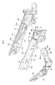
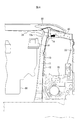
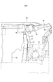
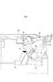
図1から図9は本発明の一実施形態を示すものであり、図1は車体前部構造の外観斜視図、図2は車体前部構造の一部分解斜視図、図3はサイドフレームの折り曲げ箇所を示す車体前部構造の一部斜視図、図4はガセットのアウタパネルへの取付状態を示す説明図、図5は車体前部構造の概略平面図、図6から図9は前面衝突時のサイドフレームの変形状態を示す説明図である。尚、図6から図9は、説明のため、部材を適宜省略して図示している。 1 to 9 show an embodiment of the present invention. FIG. 1 is an external perspective view of a vehicle body front structure, FIG. 2 is a partially exploded perspective view of the vehicle body front structure, and FIG. 4 is a partial perspective view of the vehicle body front structure showing the location, FIG. 4 is an explanatory view showing the state of attachment of the gusset to the outer panel, FIG. 5 is a schematic plan view of the vehicle body front structure, and FIGS. It is explanatory drawing which shows the deformation | transformation state of a side frame. In FIGS. 6 to 9, members are appropriately omitted for illustration purposes.
図1に示すように、車体1は、例えば鋼板をプレス成型したパネル状の部材を集成し、スポット溶接等で接合して構成されている。車体1は、前後方向へ延びる左右一対のサイドフレーム10と、各サイドフレーム10の前端側を連結し左右へ延びるラジエータロアサポート20と、ラジエータロアサポート20の両端側から上方へ延びる左右一対のラジエータパネル22と、ラジエータパネル22の上端を連結し左右へ延びるラジエータアッパサポート24と、ラジエータアッパサポート24の両端から左右外側へ向かって斜め後方へ延びる左右一対の突出部材26と、を備えている。
As shown in FIG. 1, the
また、車体1は、各サイドフレーム10の左右外側の上方にて前後方向へ延びる左右一対のアッパフレーム30と、各アッパフレーム30の前端と各サイドフレーム10の所定箇所を連結する左右一対の連結部材40と、各ラジエータパネル22の上端側と各サイドフレーム10の所定箇所を連結する左右一対の衝突時荷重伝達部材50と、を備えている。さらに、車体1は、車室とエンジンルームを仕切るトーボード60と、前輪側とエンジンルームを仕切る左右一対のホイールエプロン70と、を備えている。
The
各サイドフレーム10は、正面視の断面が矩形状の閉断面となるよう形成されている。図2に示すように、本実施形態においては、各サイドフレーム10は、インナパネル11とアウタパネル12を接合して構成され、インナパネル11のアウタパネル12側には補強部材13が設けられる。また、各サイドフレーム10の左右外側に連結部材40が接続されるとともに、各サイドフレーム10の上側に衝突時荷重伝達部材50が接続される。本実施形態においては、各サイドフレーム10は接続部材としてのガセット14を有しており、連結部材40及び衝突時荷重伝達部材50はガセット14を介してアウタパネル12に接続される。
Each
インナパネル11は、前後方向へ延び、ほぼ水平に形成される上面部11aと、上面部11aの左右方向内端から下方へ延びる内面部11bと、内面部11bの下端から左右外側へ延びる下面部11cと、を有している。また、インナパネル11は、上面部11aの左右方向外端から上方へ延びる上側接合フランジ部11dと、下面部11cの左右方向外端から下方へ延びる下側接合フランジ部11eと、を有している。
The
アウタパネル12は、前後方向へ延び、下方へ向かって左右外側へ傾斜する上傾斜面部12aと、上傾斜面部12aの左右方向外端から下方へ延びる外面部12bと、外面部12bの下端から下方へ向かって左右内側へ傾斜する下傾斜面部12cと、を有している。また、アウタパネル12は、上傾斜面部12aの左右方向内端から上方へ延びる上側接合フランジ部12dと、下傾斜面部12cの左右方向内端から下方へ延びる下側接合フランジ部12eと、を有している。
The
補強部材13は、インナパネル11の内面部11bに沿って前後方向へ延びる内面部13aと、内面部13aの下端からインナパネル11の下面部11cに沿って左右方向へ延びる下面部13bと、を有している。図3に示すように、内面部13aの上縁の所定箇所には切欠13cが形成されている。
The reinforcing
各サイドフレーム10は、インナパネル11とアウタパネル12の各上側接合フランジ部11d,12d及び各下側接合フランジ部11e,12eを接合することで、閉断面をなしている。
Each
連結部材40は、アッパフレーム30の前端とサイドフレーム10とを連結する。本実施形態においては、連結部材40は、側面視にて矩形状の閉断面を有し、ほぼ左右へ真っ直ぐに形成されている。具体的には、図2及び図3に示すように、連結部材40は、ほぼ水平な上面部40aと、上面部40aの前端から下方へ延びる前面部40bと、上面部40aの後端から下方へ延びる後面部40cと、を有している。また、連結部材40は、前面部40bの下端から前方へ延びる前側フランジ部40dと、後面部40cの下端から後方へ延びる後側フランジ部40eと、前側フランジ部40d及び後側フランジ部40eに接続される下面部(図示せず)と、を有する。
The connecting
図4(a)に示すように、ガセット14は、連結部材40の下側に重なるようサイドフレーム10側端部に設けられる。尚、図4(a)は、説明のため、ガセット14の上方に位置する衝突時荷重伝達部材50等を省略して図示している。図4(b)に示すように、ガセット14は、ほぼ水平な上面部14aと、上面部14aの前端から下方へ延びる前面部14bと、上面部14aの後端から下方へ延びる後面部14cと、前面部14bの下端から前方へ延びる第1前側フランジ部14dと、を有する。尚、図4(b)は説明のため、ガセット14の左右外側に位置する連結部材40等を省略して図示している。第1前側フランジ部14dが、連結部材40の前側フランジ部40dにスポット溶接等により接続される。
As shown in FIG. 4A, the
また、ガセット14は、上面部14aの左右内側端部から下方へ延びる上側フランジ部14fと、前面部14bの左右内側端部から前方へ延びる第2前側フランジ部14gと、後面部13cの左右内側端部の下側から後方へ延びる第2後側フランジ部14hと、を有している。上側フランジ部14fは、前後方向へ延び、インナパネル11及びアウタパネル12の各上側接合フランジ部11d,12dに沿って形成され、各上側接合フランジ部11d,12dにスポット溶接等により接続される。第2前側フランジ部14gは、概略上下方向へ延び、各上側接続フランジ部11d,12d及びアウタパネル12の上傾斜面部12aにスポット溶接等により接続される。第2後側フランジ部14hは、概略上下方向へ延び、アウタパネル12の上面傾斜部12a及び外面部12bの稜線近傍にスポット溶接等により接続される。すなわち、第2後側フランジ部14hは、サイドフレーム10の外側に接続されている。
The
図1に示すように、ラジエータロアサポート20は、両端が各サイドフレーム10の下側に接続される。本実施形態においては、ラジエータロアサポート20は、閉断面を有し、ほぼ左右に真っ直ぐに形成されている。
As shown in FIG. 1, both ends of the radiator
各ラジエータパネル22は、下端がラジエータロアサポート20の上側に接続され、上端がラジエータアッパサポート24の下側に接続される。本実施形態においては、ラジエータパネル22は、閉断面を有し、ほぼ上下に真っ直ぐに形成されている。
Each
ラジエータアッパサポート24は、両端側が各ラジエータパネル22に支持される。本実施形態においては、ラジエータアッパサポート24は、閉断面を有し、ほぼ左右に真っ直ぐに形成されている。また、ラジエータアッパサポート24の両端に突出部材26が接続される。各突出部材26は、閉断面を有し、斜め後方へ所定距離だけ延びる。本実施形態においては、各突出部材26は、フードを所期の位置で受けるために設けられている。
Both ends of the radiator
図1に示すように、各アッパフレーム30は、後方から前方へ向かって、ほぼ水平方向に延びるエプロン接続区間31と、エプロン接続区間31の前端から斜めに下る傾斜区間32と、傾斜区間の前端から水平方向に延びる前端区間33と、を有する。エプロン接続区間31の左右内側にはホイールエプロン70が接続されている。前端区間33の下面の高さは、サイドフレーム10の上面の高さとほぼ一致している。
As shown in FIG. 1, each
図1に示すように、衝突時荷重伝達部材50は、一端が各ラジエータパネル22の上端側に接続されるとともに、他端が各サイドフレーム10のガセット14を介して連結部材40に接続され、後方へ向かって下がりつつ斜め左右外側へ延びている。本実施形態においては、衝突時荷重伝達部材50は、各ラジエータパネル22の左右外側の側部に接続されている。これにより、各衝突時荷重伝達部材50がエンジンルーム内のラジエータ近傍の各種部品と接触することはない。各衝突時荷重伝達部材50は、開断面を有し、ほぼ真っ直ぐに形成されている。各衝突時荷重伝達部材50は、車両の前面衝突時にガセット14を介してサイドフレーム10に左右外側への荷重を伝達してサイドフレーム10の左右外側への第1の折り曲げを助長する。
As shown in FIG. 1, one end of the collision
ホイールエプロン70は、サイドフレーム10とアッパフレーム30のエプロン接続区間31とに跨って形成される。すなわち、各ホイールエプロン70は、左右内側が各サイドフレーム10に接続され、左右外側が各アッパフレーム30に接続される。各ホイールエプロン70は、各サイドフレーム10側でほぼ上下方向へ延び、エプロン接続区間31でほぼ水平方向へ延びる。各ホイールエプロン70には、サスペンションのストラットの上端が取り付けられるストラット取付部71が形成されている。
The
図5に示すように、各サイドフレーム10の間に、前端側が他の部分よりも左右外側へ突出する突起部91を有する原動機90が配置される。本実施形態においては、原動機90はエンジンであり、突起部91はチェーンカバーである。尚、原動機90はモータであってもよい。本実施形態においては、原動機90は左右非対称である。
As shown in FIG. 5, between each
以上のように構成された車体前部構造では、図5に示すように、サイドフレーム10は、前面衝突時に折れ曲がる3箇所の折り曲げ部10a,10b,10cを、前後方向に異なる位置に有している。第1折り曲げ部10aはガセット14の第2後側フランジ部14hの取り付け部分であり、第2折り曲げ部10bは補強部材13の切欠13cの形成部分であり、第3折り曲げ部10cは補強部材13の後端部分かつホイールエプロン70との接続部前端である。
In the vehicle body front structure configured as described above, as shown in FIG. 5, the
第1折り曲げ部10aでは、衝突時荷重伝達部材50からサイドフレーム10の外側面に左右外側への荷重が伝達されることによりサイドフレーム10が折り曲げられる。尚、本実施形態においては、サイドフレーム10の前端側にバンパビーム80が接続されるブラケットが設けられており、バンパビーム80からブラケットに荷重が伝達されることによってもサイドフレーム10が折り曲げられる。
In the
第2折り曲げ部10bでは、サイドフレーム10における強度部材13の切欠13cの前後で剛性が変化することから、サイドフレーム10に曲げ方向の負荷が加わることによりサイドフレーム10が折り曲げられる。すなわち、本実施形態においては、車両の前面衝突時にサイドフレーム10の左右内側への第2の折り曲げを助長する第1の剛性変化部は、強度部材13の切欠13cを含んでいる。
In the second
第3折り曲げ部10cでは、サイドフレーム10における強度部材13の後端及びホイールエプロン70との接続部前端の前後で剛性が変化することから、サイドフレーム10に曲げ方向の負荷が加わることによりサイドフレーム10が折り曲げられる。すなわち、本実施形態においては、車両の前面衝突時にサイドフレーム10の左右外側への第3の折り曲げを助長する第2の剛性変化部は、強度部材13の後端及びホイールエプロン70とサイドフレーム10の接続部前端を含んでいる。
In the third
図6に示すように、この車体前部構造では、車両の前面衝突時に、まず、車両の比較的前側に位置するラジエータパネル22、ラジエータアッパサポート24等が衝突対象物と干渉し、相対的に後方へ移動する。このとき、衝突時荷重伝達部材50は、前端側がラジエータパネル22とともに後方へ移動させられ、後端側が左右外側へ押し出される。衝突時荷重伝達部材50の後端は、ガセット14の後端フランジ14hを介してサイドフレーム10のアウタパネル12の外面部12bに接続されているので、サイドフレーム10の外側に左右外側への荷重が作用し、サイドフレーム10が左右外側へ折れ曲がる第1の折り曲げモードが実現される。ここで、サイドフレーム10の外側に荷重を作用させているので、例えばサイドフレーム10が圧壊するモードとなって続く第2、第3の折り曲げモードに支障をきたすことはない。また、前述のように、本実施形態においては、バンパビーム80からサイドフレーム10に取り付けられたブラケットに荷重が伝達されることによってもサイドフレーム10が折り曲げられる。
As shown in FIG. 6, in this vehicle body front structure, at the time of a frontal collision of the vehicle, first, the
図7に示すように、サイドフレーム10が衝突時荷重伝達部材50の荷重伝達により第1の折り曲げモードとなった後、さらに衝突対象物が後退すると、サイドフレーム10の当該折り曲げ部分より後ろ側に左右内側方向への負荷が生じ、サイドフレーム10が第1の剛性変化部を起点として左右内側へ折れ曲がる第2の折り曲げモードが実現される。本実施形態においては、インナパネル11及びアウタパネル12とともに補強部材13も折れ曲がることとなるので、第2の折り曲げ部10bにて吸収されるエネルギー量を増加することができる。
As shown in FIG. 7, after the
サイドフレーム10が第2の折り曲げモードとなると、サイドフレーム10の第2の折り曲げ部分は原動機90と接触する。この状態でさらに衝突対象物が後退すると、図8に示すように、原動機90の突起部91の後面が、サブフレーム10の第2の折り曲げ部分10bと接触する。これにより、図9に示すように、サイドフレーム10の当該折り曲げ部分より後ろ側に左右外側方向への負荷が生じ、サイドフレーム10が第2の剛性変化部を起点として左右外側へ折れ曲がる第3の折り曲げモードが実現される。このとき、原動機90の突起部91には、サイドフレーム10の左右内側が引っ掛かり、左右外側は引っ掛からないようにすると、効果的にサブフレーム10に左右外向きのモーメントを生じさせることができる。ここで、本実施形態においては、原動機90の突起部91が左右非対称であるので、これに応じてサイドフレーム10の第2の折り曲げ部10bも左右非対称とすることが好ましい。本実施形態においては、補強部材13によりサイドフレーム10における第2の折り曲げ部10bから第3の折り曲げ部10cの強度を向上させることにより、これらの間でサイドフレーム10が折れ曲がるようなことはなく、サイドフレーム10の折り曲げモードを安定させることができる。
When the
このようにして衝突対象物の後退量に応じて時間差をつけて3箇所にてサイドフレーム10を折り曲げることにより、衝突時に継続的にエネルギー吸収を行いつつ、サイドフレーム10の車両室内への侵入を抑制することができる。特に、第1の折り曲げ部10aにて、サイドフレーム10に衝突時荷重伝達部材50から能動的に荷重を作用させるようにしたので、サイドフレーム10の変形モードを安定させることができる。
In this way, the
ここで、蛇腹状に圧潰する部分は変形時に多くのエネルギーを吸収するものの、変形を継続するためには、次第に大きな荷重が必要となる。すなわち、変形ストロークが減少して衝突現象に要する時間が短くなり、減速度が大きくなるために乗員の頭部や胸部に与えるダメージが大きくなるおそれがある。本実施形態においては、衝突初期にバンパビームのステーを軸方向に蛇腹状に圧潰させて効率的にエネルギーを吸収させるが、その後のサイドフレーム10における変形は最終的に曲げモードであるので、乗員の頭部や胸部に与えるダメージが大きくなるおそれはない。さらに、サイドフレーム10が軸方向にトーボードを押すことがないので、乗員下肢に与えるダメージを軽減することができる。
Here, the portion crushed in a bellows shape absorbs a large amount of energy during deformation, but in order to continue the deformation, a gradually larger load is required. That is, the deformation stroke is reduced, the time required for the collision phenomenon is shortened, and the deceleration is increased, so that there is a possibility that damage to the head and chest of the occupant is increased. In the present embodiment, the stay of the bumper beam is crushed in a bellows shape in the axial direction in the initial stage of the collision to efficiently absorb energy, but the subsequent deformation in the
尚、前記実施形態においては、衝突時荷重伝達部材50が各ラジエータパネル22の側部に接続されたものを示したが、エンジンルーム内のレイアウト上の問題がなければ、各ラジエータパネル22の後部に接続されてもよい。さらには、衝突時荷重伝達部材50がラジエータアッパサポート24に接続されてもよい。また、衝突時荷重伝達部材50がガセット14を介してサイドフレーム10に接続されるものを示したが、ガセット14を設けることなく衝突時荷重伝達部材50を連結部材40に接続してもよい。この場合、連結部材40が接続部材として機能することとなる。
In the above embodiment, the collision
また、前記実施形態においては、補強部材13の切欠13cを第1の剛性変化部として利用したものを示したが、切欠13c以外にもビード、孔等を形成することにより剛性変化部とすることもできる。また、補強部材13を設けることなく、サイドフレーム10に直接ビード、孔等を形成して剛性変化部とすることも可能である。さらに、前記実施形態においては、補強部材13の後端及びホイールエプロン70とサイドフレーム10との接続部前端を第2の剛性変化部として利用したものを示したが、例えばサイドフレーム10にビード、孔等を形成して剛性変化部とすることも可能である。
Moreover, in the said embodiment, although what used the notch 13c of the
また、前記実施形態においては、前面衝突時にサイドフレーム10が原動機90と接触するものを示したが、例えばトランスミッションのような他のパワーユニットと接触するものであってもよい。また、衝突前から原動機90に突起部91が形成されているものを示したが、衝突中にパワーユニットが変形して突出部が形成されるものであってもよい。
Moreover, in the said embodiment, although the
以上、本発明の実施の形態を説明したが、上記に記載した実施の形態は特許請求の範囲に係る発明を限定するものではない。また、実施の形態の中で説明した特徴の組合せの全てが発明の課題を解決するための手段に必須であるとは限らない点に留意すべきである。 While the embodiments of the present invention have been described above, the embodiments described above do not limit the invention according to the claims. In addition, it should be noted that not all the combinations of features described in the embodiments are essential to the means for solving the problems of the invention.
10 サイドフレーム
10a 第1の折り曲げ部
10b 第2の折り曲げ部
10c 第3の折り曲げ部
13 補強部材
13c 切欠
14 ガセット
20 ラジエータロアサポート
22 ラジエータパネル
24 ラジエータアッパサポート
50 衝突時荷重伝達部材
70 ホイールエプロン
DESCRIPTION OF
Claims (5)
前記各サイドフレームの前端側を連結し左右へ延びるラジエータロアサポートと、
前記ラジエータロアサポートの両端側から上方へ延びる左右一対のラジエータパネルと、
前記各ラジエータパネルの上端を連結し左右へ延びるラジエータアッパサポートと、
前記サイドフレームの左右外側に接続される接続部材と、
一端が前記ラジエータアッパサポートまたは前記ラジエータパネルに接続されるとともに他端が前記接続部材に接続され、後方へ向かって下がりつつ斜め左右外側へ延び、車両の前面衝突時に前記接続部材を介して前記サイドフレームに左右外側への荷重を伝達して前記サイドフレームの左右外側への第1の折り曲げを助長する衝突時荷重伝達部材と、を備える車体前部構造。 A pair of left and right side frames extending in the front-rear direction;
A radiator lower support that connects the front end side of each side frame and extends to the left and right,
A pair of left and right radiator panels extending upward from both ends of the radiator lower support;
A radiator upper support that connects the upper ends of the radiator panels and extends left and right;
A connection member connected to the left and right outer sides of the side frame;
One end is connected to the radiator upper support or the radiator panel, and the other end is connected to the connecting member, and extends obliquely left and right while descending rearward. A vehicle body front structure comprising: a load transmitting member at the time of collision that transmits a load to the left and right outer sides of the frame to promote the first bending of the side frame to the left and right outer sides.
車両の前面衝突時に、前記第1の剛性変化部で折り曲げられたサイドフレームは、前記パワーユニットの前記突起部の後面と接触する請求項3に記載の車体前部構造。 Wherein disposed between the side frames, it includes a power unit protrusion protruding to the left outer right is formed,
The vehicle body front part structure according to claim 3, wherein the side frame bent at the first rigidity changing portion is in contact with a rear surface of the protruding portion of the power unit at the time of a frontal collision of the vehicle.
前記第1の剛性変化部は、前記補強部材の切欠を含み、
前記第2の剛性変化部は、前記補強部材の後端を含む請求項3または4に記載の車体前部構造。 The side frame has a reinforcing member disposed inside the closed cross section,
The first rigidity changing portion includes a cutout of the reinforcing member,
The vehicle body front part structure according to claim 3 or 4, wherein the second rigidity changing portion includes a rear end of the reinforcing member.
Priority Applications (1)
| Application Number | Priority Date | Filing Date | Title |
|---|---|---|---|
| JP2013203779A JP6169934B2 (en) | 2013-09-30 | 2013-09-30 | Body front structure |
Applications Claiming Priority (1)
| Application Number | Priority Date | Filing Date | Title |
|---|---|---|---|
| JP2013203779A JP6169934B2 (en) | 2013-09-30 | 2013-09-30 | Body front structure |
Publications (2)
| Publication Number | Publication Date |
|---|---|
| JP2015067158A JP2015067158A (en) | 2015-04-13 |
| JP6169934B2 true JP6169934B2 (en) | 2017-07-26 |
Family
ID=52834304
Family Applications (1)
| Application Number | Title | Priority Date | Filing Date |
|---|---|---|---|
| JP2013203779A Active JP6169934B2 (en) | 2013-09-30 | 2013-09-30 | Body front structure |
Country Status (1)
| Country | Link |
|---|---|
| JP (1) | JP6169934B2 (en) |
Family Cites Families (5)
| Publication number | Priority date | Publication date | Assignee | Title |
|---|---|---|---|---|
| JP3446718B2 (en) * | 2000-04-25 | 2003-09-16 | 日産自動車株式会社 | Car body structure |
| JP4144376B2 (en) * | 2003-02-27 | 2008-09-03 | 三菱自動車工業株式会社 | Front body structure |
| JP2006192983A (en) * | 2005-01-11 | 2006-07-27 | Fuji Heavy Ind Ltd | Front structure of vehicle body |
| JP4945324B2 (en) * | 2007-05-31 | 2012-06-06 | 本田技研工業株式会社 | Body front structure |
| JP5357953B2 (en) * | 2011-04-01 | 2013-12-04 | 本田技研工業株式会社 | Body front structure |
-
2013
- 2013-09-30 JP JP2013203779A patent/JP6169934B2/en active Active
Also Published As
| Publication number | Publication date |
|---|---|
| JP2015067158A (en) | 2015-04-13 |
Similar Documents
| Publication | Publication Date | Title |
|---|---|---|
| JP5581389B2 (en) | Body front structure | |
| JP6550641B2 (en) | Front body structure of the vehicle | |
| JP6235628B2 (en) | Auto body structure | |
| JP5836418B2 (en) | Body front structure | |
| CN105339243A (en) | Vehicle body front structure of a vehicle | |
| JP2003127893A (en) | Front structure of vehicle body | |
| JP2007112260A (en) | Front bodywork of vehicle | |
| JP2006232147A (en) | Vehicle body front structure | |
| JP6139501B2 (en) | Body front structure | |
| JP6102870B2 (en) | Body front structure | |
| JP6079708B2 (en) | Front body structure of the vehicle | |
| JP6252572B2 (en) | Body front structure | |
| KR102371242B1 (en) | Front vehicle body reinforcing structure | |
| JP6112087B2 (en) | Vehicle front structure | |
| JP2013103650A (en) | Vehicle body floor structure | |
| JP7020351B2 (en) | Vehicle front body structure | |
| JP3632654B2 (en) | Body front structure | |
| JP2013147189A (en) | Vehicle body front structure | |
| JP6169934B2 (en) | Body front structure | |
| JP2008132830A (en) | Front part structure for vehicle | |
| JP5026136B2 (en) | Body frame structure | |
| JP6044795B2 (en) | Front body structure of the vehicle | |
| JP2022083565A (en) | Vehicle body structure | |
| JP6052231B2 (en) | Vehicle body structure | |
| JP6252080B2 (en) | Auto body front structure |
Legal Events
| Date | Code | Title | Description |
|---|---|---|---|
| A621 | Written request for application examination |
Free format text: JAPANESE INTERMEDIATE CODE: A621 Effective date: 20160608 |
|
| A977 | Report on retrieval |
Free format text: JAPANESE INTERMEDIATE CODE: A971007 Effective date: 20170303 |
|
| A131 | Notification of reasons for refusal |
Free format text: JAPANESE INTERMEDIATE CODE: A131 Effective date: 20170314 |
|
| A521 | Request for written amendment filed |
Free format text: JAPANESE INTERMEDIATE CODE: A523 Effective date: 20170512 |
|
| TRDD | Decision of grant or rejection written | ||
| A01 | Written decision to grant a patent or to grant a registration (utility model) |
Free format text: JAPANESE INTERMEDIATE CODE: A01 Effective date: 20170606 |
|
| A61 | First payment of annual fees (during grant procedure) |
Free format text: JAPANESE INTERMEDIATE CODE: A61 Effective date: 20170629 |
|
| R150 | Certificate of patent or registration of utility model |
Ref document number: 6169934 Country of ref document: JP Free format text: JAPANESE INTERMEDIATE CODE: R150 |
|
| R250 | Receipt of annual fees |
Free format text: JAPANESE INTERMEDIATE CODE: R250 |
|
| R250 | Receipt of annual fees |
Free format text: JAPANESE INTERMEDIATE CODE: R250 |
|
| R250 | Receipt of annual fees |
Free format text: JAPANESE INTERMEDIATE CODE: R250 |
|
| R250 | Receipt of annual fees |
Free format text: JAPANESE INTERMEDIATE CODE: R250 |