JP6162217B2 - Laser support tool production and repair method - Google Patents
Laser support tool production and repair method Download PDFInfo
- Publication number
- JP6162217B2 JP6162217B2 JP2015506050A JP2015506050A JP6162217B2 JP 6162217 B2 JP6162217 B2 JP 6162217B2 JP 2015506050 A JP2015506050 A JP 2015506050A JP 2015506050 A JP2015506050 A JP 2015506050A JP 6162217 B2 JP6162217 B2 JP 6162217B2
- Authority
- JP
- Japan
- Prior art keywords
- layer
- tool
- feature
- forming surface
- support body
- Prior art date
- Legal status (The legal status is an assumption and is not a legal conclusion. Google has not performed a legal analysis and makes no representation as to the accuracy of the status listed.)
- Active
Links
Images


Classifications
-
- B—PERFORMING OPERATIONS; TRANSPORTING
- B23—MACHINE TOOLS; METAL-WORKING NOT OTHERWISE PROVIDED FOR
- B23K—SOLDERING OR UNSOLDERING; WELDING; CLADDING OR PLATING BY SOLDERING OR WELDING; CUTTING BY APPLYING HEAT LOCALLY, e.g. FLAME CUTTING; WORKING BY LASER BEAM
- B23K35/00—Rods, electrodes, materials, or media, for use in soldering, welding, or cutting
- B23K35/22—Rods, electrodes, materials, or media, for use in soldering, welding, or cutting characterised by the composition or nature of the material
- B23K35/24—Selection of soldering or welding materials proper
- B23K35/30—Selection of soldering or welding materials proper with the principal constituent melting at less than 1550 degrees C
- B23K35/3046—Co as the principal constituent
-
- B—PERFORMING OPERATIONS; TRANSPORTING
- B21—MECHANICAL METAL-WORKING WITHOUT ESSENTIALLY REMOVING MATERIAL; PUNCHING METAL
- B21D—WORKING OR PROCESSING OF SHEET METAL OR METAL TUBES, RODS OR PROFILES WITHOUT ESSENTIALLY REMOVING MATERIAL; PUNCHING METAL
- B21D22/00—Shaping without cutting, by stamping, spinning, or deep-drawing
-
- B—PERFORMING OPERATIONS; TRANSPORTING
- B22—CASTING; POWDER METALLURGY
- B22F—WORKING METALLIC POWDER; MANUFACTURE OF ARTICLES FROM METALLIC POWDER; MAKING METALLIC POWDER; APPARATUS OR DEVICES SPECIALLY ADAPTED FOR METALLIC POWDER
- B22F10/00—Additive manufacturing of workpieces or articles from metallic powder
- B22F10/20—Direct sintering or melting
- B22F10/25—Direct deposition of metal particles, e.g. direct metal deposition [DMD] or laser engineered net shaping [LENS]
-
- B—PERFORMING OPERATIONS; TRANSPORTING
- B22—CASTING; POWDER METALLURGY
- B22F—WORKING METALLIC POWDER; MANUFACTURE OF ARTICLES FROM METALLIC POWDER; MAKING METALLIC POWDER; APPARATUS OR DEVICES SPECIALLY ADAPTED FOR METALLIC POWDER
- B22F10/00—Additive manufacturing of workpieces or articles from metallic powder
- B22F10/40—Structures for supporting workpieces or articles during manufacture and removed afterwards
- B22F10/47—Structures for supporting workpieces or articles during manufacture and removed afterwards characterised by structural features
-
- B—PERFORMING OPERATIONS; TRANSPORTING
- B22—CASTING; POWDER METALLURGY
- B22F—WORKING METALLIC POWDER; MANUFACTURE OF ARTICLES FROM METALLIC POWDER; MAKING METALLIC POWDER; APPARATUS OR DEVICES SPECIALLY ADAPTED FOR METALLIC POWDER
- B22F12/00—Apparatus or devices specially adapted for additive manufacturing; Auxiliary means for additive manufacturing; Combinations of additive manufacturing apparatus or devices with other processing apparatus or devices
- B22F12/50—Means for feeding of material, e.g. heads
- B22F12/55—Two or more means for feeding material
-
- B—PERFORMING OPERATIONS; TRANSPORTING
- B22—CASTING; POWDER METALLURGY
- B22F—WORKING METALLIC POWDER; MANUFACTURE OF ARTICLES FROM METALLIC POWDER; MAKING METALLIC POWDER; APPARATUS OR DEVICES SPECIALLY ADAPTED FOR METALLIC POWDER
- B22F5/00—Manufacture of workpieces or articles from metallic powder characterised by the special shape of the product
- B22F5/007—Manufacture of workpieces or articles from metallic powder characterised by the special shape of the product of moulds
-
- B—PERFORMING OPERATIONS; TRANSPORTING
- B23—MACHINE TOOLS; METAL-WORKING NOT OTHERWISE PROVIDED FOR
- B23K—SOLDERING OR UNSOLDERING; WELDING; CLADDING OR PLATING BY SOLDERING OR WELDING; CUTTING BY APPLYING HEAT LOCALLY, e.g. FLAME CUTTING; WORKING BY LASER BEAM
- B23K26/00—Working by laser beam, e.g. welding, cutting or boring
- B23K26/20—Bonding
- B23K26/32—Bonding taking account of the properties of the material involved
- B23K26/323—Bonding taking account of the properties of the material involved involving parts made of dissimilar metallic material
-
- B—PERFORMING OPERATIONS; TRANSPORTING
- B23—MACHINE TOOLS; METAL-WORKING NOT OTHERWISE PROVIDED FOR
- B23K—SOLDERING OR UNSOLDERING; WELDING; CLADDING OR PLATING BY SOLDERING OR WELDING; CUTTING BY APPLYING HEAT LOCALLY, e.g. FLAME CUTTING; WORKING BY LASER BEAM
- B23K26/00—Working by laser beam, e.g. welding, cutting or boring
- B23K26/34—Laser welding for purposes other than joining
- B23K26/342—Build-up welding
-
- B—PERFORMING OPERATIONS; TRANSPORTING
- B23—MACHINE TOOLS; METAL-WORKING NOT OTHERWISE PROVIDED FOR
- B23K—SOLDERING OR UNSOLDERING; WELDING; CLADDING OR PLATING BY SOLDERING OR WELDING; CUTTING BY APPLYING HEAT LOCALLY, e.g. FLAME CUTTING; WORKING BY LASER BEAM
- B23K35/00—Rods, electrodes, materials, or media, for use in soldering, welding, or cutting
- B23K35/02—Rods, electrodes, materials, or media, for use in soldering, welding, or cutting characterised by mechanical features, e.g. shape
- B23K35/0222—Rods, electrodes, materials, or media, for use in soldering, welding, or cutting characterised by mechanical features, e.g. shape for use in soldering, brazing
- B23K35/0244—Powders, particles or spheres; Preforms made therefrom
-
- B—PERFORMING OPERATIONS; TRANSPORTING
- B23—MACHINE TOOLS; METAL-WORKING NOT OTHERWISE PROVIDED FOR
- B23K—SOLDERING OR UNSOLDERING; WELDING; CLADDING OR PLATING BY SOLDERING OR WELDING; CUTTING BY APPLYING HEAT LOCALLY, e.g. FLAME CUTTING; WORKING BY LASER BEAM
- B23K35/00—Rods, electrodes, materials, or media, for use in soldering, welding, or cutting
- B23K35/22—Rods, electrodes, materials, or media, for use in soldering, welding, or cutting characterised by the composition or nature of the material
- B23K35/24—Selection of soldering or welding materials proper
- B23K35/30—Selection of soldering or welding materials proper with the principal constituent melting at less than 1550 degrees C
- B23K35/3053—Fe as the principal constituent
-
- B—PERFORMING OPERATIONS; TRANSPORTING
- B23—MACHINE TOOLS; METAL-WORKING NOT OTHERWISE PROVIDED FOR
- B23P—METAL-WORKING NOT OTHERWISE PROVIDED FOR; COMBINED OPERATIONS; UNIVERSAL MACHINE TOOLS
- B23P15/00—Making specific metal objects by operations not covered by a single other subclass or a group in this subclass
- B23P15/24—Making specific metal objects by operations not covered by a single other subclass or a group in this subclass dies
-
- B—PERFORMING OPERATIONS; TRANSPORTING
- B23—MACHINE TOOLS; METAL-WORKING NOT OTHERWISE PROVIDED FOR
- B23P—METAL-WORKING NOT OTHERWISE PROVIDED FOR; COMBINED OPERATIONS; UNIVERSAL MACHINE TOOLS
- B23P6/00—Restoring or reconditioning objects
-
- B—PERFORMING OPERATIONS; TRANSPORTING
- B32—LAYERED PRODUCTS
- B32B—LAYERED PRODUCTS, i.e. PRODUCTS BUILT-UP OF STRATA OF FLAT OR NON-FLAT, e.g. CELLULAR OR HONEYCOMB, FORM
- B32B15/00—Layered products comprising a layer of metal
- B32B15/01—Layered products comprising a layer of metal all layers being exclusively metallic
- B32B15/013—Layered products comprising a layer of metal all layers being exclusively metallic one layer being formed of an iron alloy or steel, another layer being formed of a metal other than iron or aluminium
-
- B—PERFORMING OPERATIONS; TRANSPORTING
- B22—CASTING; POWDER METALLURGY
- B22F—WORKING METALLIC POWDER; MANUFACTURE OF ARTICLES FROM METALLIC POWDER; MAKING METALLIC POWDER; APPARATUS OR DEVICES SPECIALLY ADAPTED FOR METALLIC POWDER
- B22F10/00—Additive manufacturing of workpieces or articles from metallic powder
- B22F10/60—Treatment of workpieces or articles after build-up
- B22F10/66—Treatment of workpieces or articles after build-up by mechanical means
-
- B—PERFORMING OPERATIONS; TRANSPORTING
- B22—CASTING; POWDER METALLURGY
- B22F—WORKING METALLIC POWDER; MANUFACTURE OF ARTICLES FROM METALLIC POWDER; MAKING METALLIC POWDER; APPARATUS OR DEVICES SPECIALLY ADAPTED FOR METALLIC POWDER
- B22F5/00—Manufacture of workpieces or articles from metallic powder characterised by the special shape of the product
- B22F2005/001—Cutting tools, earth boring or grinding tool other than table ware
-
- B—PERFORMING OPERATIONS; TRANSPORTING
- B22—CASTING; POWDER METALLURGY
- B22F—WORKING METALLIC POWDER; MANUFACTURE OF ARTICLES FROM METALLIC POWDER; MAKING METALLIC POWDER; APPARATUS OR DEVICES SPECIALLY ADAPTED FOR METALLIC POWDER
- B22F7/00—Manufacture of composite layers, workpieces, or articles, comprising metallic powder, by sintering the powder, with or without compacting wherein at least one part is obtained by sintering or compression
- B22F7/06—Manufacture of composite layers, workpieces, or articles, comprising metallic powder, by sintering the powder, with or without compacting wherein at least one part is obtained by sintering or compression of composite workpieces or articles from parts, e.g. to form tipped tools
- B22F7/062—Manufacture of composite layers, workpieces, or articles, comprising metallic powder, by sintering the powder, with or without compacting wherein at least one part is obtained by sintering or compression of composite workpieces or articles from parts, e.g. to form tipped tools involving the connection or repairing of preformed parts
- B22F2007/068—Manufacture of composite layers, workpieces, or articles, comprising metallic powder, by sintering the powder, with or without compacting wherein at least one part is obtained by sintering or compression of composite workpieces or articles from parts, e.g. to form tipped tools involving the connection or repairing of preformed parts repairing articles
-
- B—PERFORMING OPERATIONS; TRANSPORTING
- B23—MACHINE TOOLS; METAL-WORKING NOT OTHERWISE PROVIDED FOR
- B23K—SOLDERING OR UNSOLDERING; WELDING; CLADDING OR PLATING BY SOLDERING OR WELDING; CUTTING BY APPLYING HEAT LOCALLY, e.g. FLAME CUTTING; WORKING BY LASER BEAM
- B23K2103/00—Materials to be soldered, welded or cut
- B23K2103/02—Iron or ferrous alloys
-
- B—PERFORMING OPERATIONS; TRANSPORTING
- B23—MACHINE TOOLS; METAL-WORKING NOT OTHERWISE PROVIDED FOR
- B23K—SOLDERING OR UNSOLDERING; WELDING; CLADDING OR PLATING BY SOLDERING OR WELDING; CUTTING BY APPLYING HEAT LOCALLY, e.g. FLAME CUTTING; WORKING BY LASER BEAM
- B23K2103/00—Materials to be soldered, welded or cut
- B23K2103/08—Non-ferrous metals or alloys
-
- B—PERFORMING OPERATIONS; TRANSPORTING
- B23—MACHINE TOOLS; METAL-WORKING NOT OTHERWISE PROVIDED FOR
- B23K—SOLDERING OR UNSOLDERING; WELDING; CLADDING OR PLATING BY SOLDERING OR WELDING; CUTTING BY APPLYING HEAT LOCALLY, e.g. FLAME CUTTING; WORKING BY LASER BEAM
- B23K2103/00—Materials to be soldered, welded or cut
- B23K2103/18—Dissimilar materials
- B23K2103/26—Alloys of Nickel and Cobalt and Chromium
-
- B—PERFORMING OPERATIONS; TRANSPORTING
- B23—MACHINE TOOLS; METAL-WORKING NOT OTHERWISE PROVIDED FOR
- B23K—SOLDERING OR UNSOLDERING; WELDING; CLADDING OR PLATING BY SOLDERING OR WELDING; CUTTING BY APPLYING HEAT LOCALLY, e.g. FLAME CUTTING; WORKING BY LASER BEAM
- B23K2103/00—Materials to be soldered, welded or cut
- B23K2103/50—Inorganic material, e.g. metals, not provided for in B23K2103/02 – B23K2103/26
-
- B—PERFORMING OPERATIONS; TRANSPORTING
- B23—MACHINE TOOLS; METAL-WORKING NOT OTHERWISE PROVIDED FOR
- B23P—METAL-WORKING NOT OTHERWISE PROVIDED FOR; COMBINED OPERATIONS; UNIVERSAL MACHINE TOOLS
- B23P15/00—Making specific metal objects by operations not covered by a single other subclass or a group in this subclass
- B23P15/24—Making specific metal objects by operations not covered by a single other subclass or a group in this subclass dies
- B23P15/246—Laminated dies
-
- C—CHEMISTRY; METALLURGY
- C23—COATING METALLIC MATERIAL; COATING MATERIAL WITH METALLIC MATERIAL; CHEMICAL SURFACE TREATMENT; DIFFUSION TREATMENT OF METALLIC MATERIAL; COATING BY VACUUM EVAPORATION, BY SPUTTERING, BY ION IMPLANTATION OR BY CHEMICAL VAPOUR DEPOSITION, IN GENERAL; INHIBITING CORROSION OF METALLIC MATERIAL OR INCRUSTATION IN GENERAL
- C23C—COATING METALLIC MATERIAL; COATING MATERIAL WITH METALLIC MATERIAL; SURFACE TREATMENT OF METALLIC MATERIAL BY DIFFUSION INTO THE SURFACE, BY CHEMICAL CONVERSION OR SUBSTITUTION; COATING BY VACUUM EVAPORATION, BY SPUTTERING, BY ION IMPLANTATION OR BY CHEMICAL VAPOUR DEPOSITION, IN GENERAL
- C23C4/00—Coating by spraying the coating material in the molten state, e.g. by flame, plasma or electric discharge
- C23C4/04—Coating by spraying the coating material in the molten state, e.g. by flame, plasma or electric discharge characterised by the coating material
- C23C4/06—Metallic material
-
- Y—GENERAL TAGGING OF NEW TECHNOLOGICAL DEVELOPMENTS; GENERAL TAGGING OF CROSS-SECTIONAL TECHNOLOGIES SPANNING OVER SEVERAL SECTIONS OF THE IPC; TECHNICAL SUBJECTS COVERED BY FORMER USPC CROSS-REFERENCE ART COLLECTIONS [XRACs] AND DIGESTS
- Y02—TECHNOLOGIES OR APPLICATIONS FOR MITIGATION OR ADAPTATION AGAINST CLIMATE CHANGE
- Y02P—CLIMATE CHANGE MITIGATION TECHNOLOGIES IN THE PRODUCTION OR PROCESSING OF GOODS
- Y02P10/00—Technologies related to metal processing
- Y02P10/25—Process efficiency
-
- Y—GENERAL TAGGING OF NEW TECHNOLOGICAL DEVELOPMENTS; GENERAL TAGGING OF CROSS-SECTIONAL TECHNOLOGIES SPANNING OVER SEVERAL SECTIONS OF THE IPC; TECHNICAL SUBJECTS COVERED BY FORMER USPC CROSS-REFERENCE ART COLLECTIONS [XRACs] AND DIGESTS
- Y10—TECHNICAL SUBJECTS COVERED BY FORMER USPC
- Y10T—TECHNICAL SUBJECTS COVERED BY FORMER US CLASSIFICATION
- Y10T29/00—Metal working
- Y10T29/49—Method of mechanical manufacture
- Y10T29/49718—Repairing
- Y10T29/49746—Repairing by applying fluent material, e.g., coating, casting
-
- Y—GENERAL TAGGING OF NEW TECHNOLOGICAL DEVELOPMENTS; GENERAL TAGGING OF CROSS-SECTIONAL TECHNOLOGIES SPANNING OVER SEVERAL SECTIONS OF THE IPC; TECHNICAL SUBJECTS COVERED BY FORMER USPC CROSS-REFERENCE ART COLLECTIONS [XRACs] AND DIGESTS
- Y10—TECHNICAL SUBJECTS COVERED BY FORMER USPC
- Y10T—TECHNICAL SUBJECTS COVERED BY FORMER US CLASSIFICATION
- Y10T29/00—Metal working
- Y10T29/49—Method of mechanical manufacture
- Y10T29/4998—Combined manufacture including applying or shaping of fluent material
- Y10T29/49982—Coating
- Y10T29/49986—Subsequent to metal working
Description
本発明は、一般に、工具、例えば自動車及び他の製造業界で用いられるダイ及び金型を製作する方法に関する。特に、本発明は、かかる工具の形成面上に特徴部を形成し又はかかる特徴部を補修するために鋳鉄又は他の低級の鋳造可能な材料で作られたベース構造体上に工具鋼合金をレーザクラッド(laser cladding)する方法及びかかる方法を用いて製作された工具に関する。 The present invention relates generally to a method of making dies and molds for use in tools such as automobiles and other manufacturing industries. In particular, the present invention provides a tool steel alloy on a base structure made of cast iron or other lower castable material to form features on or repair such features. The present invention relates to a method of laser cladding and a tool made using such a method.
〔関連出願の説明〕
本願は、2012年4月16日に出願された米国特許仮出願第61/624,562号(発明の名称:PROCESS FOR LASER-ASSISTED TOOL BUILD AND REPAIR)の権益主張出願であり、この米国特許仮出願を参照により引用し、その開示内容全体を本明細書の一部とする。
[Description of related applications]
This application is a US patent provisional application 61 / 624,562 filed on April 16, 2012 (invention name: PROCESS FOR LASER-ASSISTED TOOL BUILD AND REPAIR). The application is cited by reference, the entire disclosure of which is hereby incorporated by reference.
ダイ及び金型は、自動車及び他の製造業界で用いられる工具の例である。かかる工具は、所望の形状又は設計を備えた完成品を製作するための特徴部を備えている。例えば、自動車の車体パネルを製造するために用いられるダイは、相補する向かい合った表面特徴部を有する形成面を含むパンチ・ダイブロック組立体を有する場合がある。ダイ部品は、シート板金ブランクが装入されたプレス内に設け、次に作業トン数下で互いに結合し、それによりダイ部品相互間で板金ブランクを変形させる。ダイ部品を互いに結合すると、板金ブランクは引き伸ばされ、そしてダイ部品の形成面上に存在する特徴部の形状に合致する。このように、「竜巻線(Tornado line)」又は他のデザイン上の特徴部を備えた自動車の車体パネルを形成することができる。 Dies and molds are examples of tools used in the automobile and other manufacturing industries. Such tools include features for producing a finished product with a desired shape or design. For example, a die used to manufacture a car body panel of an automobile may have a punch and die block assembly that includes a forming surface having complementary opposing surface features. The die parts are provided in a press loaded with sheet metal blanks and then bonded together under a working tonnage, thereby deforming the sheet metal blanks between the die parts. When the die parts are joined together, the sheet metal blank is stretched and conforms to the shape of the features present on the forming surface of the die part. In this way, vehicle body panels with “Tornado line” or other design features can be formed.
ダイ及び金型の製作では、完成品を作るための所望の特徴部を備えた形成面を形成するよう不必要なバルク鍛造又は鋳造材料を除去するために相当な機械加工が必要である。典型的には、バルク鍛造材料は、比較的高価な工具鋼合金又は鉄である。事実、完成品を製造する費用は、主として、材料費及び必要な機械加工作業の量による。残念ながら、板金ブランクを引き伸ばして変形させるプロセスにより、工具の形成面が研磨され、その結果、相当な摩耗及び裂けが生じ、それによりかかる工具の有効寿命が限られる。特に、「竜巻線」又は他の同様なデザインを作るために用いられる鮮明な特徴部は、非常に摩耗しやすい。これは、板金ブランクが工具の他の部分内で起こる程度よりも大きな程度にわたり工具の鮮明な特徴部に対して摺動するからであり、しかも鮮明な特徴部が脆く、かくして工具の他の表面部分と比較して損傷及び摩耗を生じがちだからである。かかる工具の有効寿命を延ばすことを目的として、材料の硬度を増大させ、かくして鮮明な特徴部の耐摩耗性を増大させるために鮮明な特徴部に熱処理プロセスを施すことが知られている。しかしながら、最終的には、工具は、使用できないほど摩耗状態になり、これを補修しなければならず又は考えられる有限数の補修後、相当な費用をかけて交換しなければならない。一般的に言って、かかる工具を修繕することは、費用効果が良くない。 Die and mold fabrication requires considerable machining to remove unnecessary bulk forging or casting material to form a forming surface with the desired features for making the finished product. Typically, the bulk forging material is a relatively expensive tool steel alloy or iron. In fact, the cost of manufacturing the finished product is mainly due to material costs and the amount of machining work required. Unfortunately, the process of stretching and deforming the sheet metal blanks polishes the forming surface of the tool, resulting in considerable wear and tear, thereby limiting the useful life of such tools. In particular, the sharp features used to make “dragon winding” or other similar designs are very prone to wear. This is because the sheet metal blank slides against the sharp features of the tool to a greater extent than occurs in other parts of the tool, and the sharp features are brittle and thus other surfaces of the tool. This is because damage and wear tend to occur compared to the portion. For the purpose of extending the useful life of such tools, it is known to subject the sharp features to a heat treatment process in order to increase the hardness of the material and thus increase the wear resistance of the sharp features. Eventually, however, the tool becomes worn out of use and must be repaired or replaced at a considerable cost after a finite number of possible repairs. Generally speaking, repairing such tools is not cost effective.
国際公開第2009/077524号パンフレットでは、安価な材料、例えば高抵抗コンクリートを所望の形状に注型し、次にこれを金属又はセラミック層で被覆することによってかかる安価な材料から工具を作る方法が記載されている。この方式によれば、安価なコンクリートが鉄合金に代えて用いられるので工具の材料費が節減され、しかも形成面を構成するのに被着金属又はセラミックの比較的薄い層だけを除去する必要があるに過ぎないので機械加工の要件が軽減される。残念ながら、この方法を用いて作られた工具は、幾分脆く、これら工具が高い圧縮荷重に対して耐性がある場合でも、引張り応力状態下のこれらの抵抗は低い。工具が非常に長いライフサイクルを備える必要がない場合、安価な工具を製作する方法が適していることが示唆される。 In WO 2009/077524 there is a method of making a tool from such an inexpensive material by casting an inexpensive material, eg high resistance concrete, into a desired shape and then coating it with a metal or ceramic layer. Have been described. According to this method, since inexpensive concrete is used instead of iron alloy, the material cost of the tool is saved, and only a relatively thin layer of deposited metal or ceramic needs to be removed to form the forming surface. Only there is a reduction in machining requirements. Unfortunately, the tools made using this method are somewhat brittle and their resistance under tensile stress conditions is low even if they are resistant to high compressive loads. If the tool does not need to have a very long life cycle, it suggests that an inexpensive tooling method is suitable.
国際公開第2009/090622号パンフレットでは、金属キャビティ金型の予想寿命を延ばす方法が記載されている。特に、この方法は、ガラス物品、例えば瓶を製作するために用いられる金型内の欠陥を補修するための方法である。金型が摩耗又は損傷状態になると、金属の層を形成面全体から機械加工により除去し、次に機械加工ステップ中に除去された金属の層よりも厚い充填金属の層を機械加工面に被着させ、最後に、充填材料をガラス物品を形成するための設計上の寸法に合わせて機械加工する。残念ながら、欠陥を補修するためには形成面全体を機械加工しなければならず、これによりコストが増大する。さらに、クラッド層を形成するための充填材料は、金型の鋳鉄と冶金学的に適合性又は両立性がなければならないことが記載されている。この要件により、クラッド層を形成するために用いることができる材料の種類に制約が課される。その結果、形成面の材料特性を変化させる能力が制限される。 International Publication No. 2009/090622 pamphlet describes a method for extending the expected life of a metal cavity mold. In particular, this method is a method for repairing defects in molds used to make glass articles, such as bottles. When the mold becomes worn or damaged, the metal layer is removed from the entire forming surface by machining, and then a layer of filled metal that is thicker than the metal layer removed during the machining step is applied to the machining surface. Finally, the filler material is machined to the design dimensions for forming the glass article. Unfortunately, to repair the defects, the entire forming surface must be machined, which increases costs. It is further described that the filler material for forming the cladding layer must be metallurgically compatible or compatible with the cast iron of the mold. This requirement places constraints on the types of materials that can be used to form the cladding layer. As a result, the ability to change the material properties of the forming surface is limited.
上述の方法はいずれも、量産的A級又はクラスA(Class A)自動車用途又は他の類似の製造業界で用いるための工具を製作するには適していない。加うるに、上述の方法はいずれも、工具の材料費の節減を達成せず、しかも工具の有効寿命を延ばすことができない。さらに、上述の方法はいずれも、冶金学的に不適合な材料又は不適合な機械的性質を有する材料から工具を製作するには適していない。 None of the methods described above are suitable for making tools for use in mass-produced Class A or Class A automotive applications or other similar manufacturing industries. In addition, none of the above-described methods achieves a reduction in tool material costs and cannot extend the useful life of the tool. Furthermore, none of the methods described above are suitable for making tools from metallurgically incompatible materials or materials with incompatible mechanical properties.
したがって、先行技術の上述の問題点及び欠点のうちの少なくとも幾つかを解決する工具の製作方法及びこの方法に従って製作された工具を提供することが有益である。 Accordingly, it would be beneficial to provide a method of making a tool that solves at least some of the above-mentioned problems and disadvantages of the prior art and a tool made in accordance with this method.
本発明の少なくとも1つの実施形態の観点によれば、造形品を形成する工具であって、この工具は、第1の材料から二次加工された支持本体を有し、支持本体の第1の材料は、工具の形成面の第1の部分を構成し、この工具は、支持本体上に支持された特徴部を更に有し、かかる特徴部は、支持本体の第1の材料上に支持された第2の材料層と、第2の材料層上に支持された第3の材料層と、第3の材料層上に支持された第4の材料層とを含み、第4の材料層は、工具の形成面の第2の部分を構成し、形成面の第1の部分と形成面の第2の部分は、造形品の所望の形状を形成するよう協働することを特徴とする工具が開示される。 According to an aspect of at least one embodiment of the present invention, a tool for forming a shaped article, the tool having a support body that is secondary processed from a first material, the first of the support bodies The material constitutes a first part of the forming surface of the tool, the tool further comprising a feature supported on the support body, the feature being supported on the first material of the support body. A second material layer, a third material layer supported on the second material layer, and a fourth material layer supported on the third material layer, wherein the fourth material layer comprises: Forming a second part of the forming surface of the tool, wherein the first part of the forming surface and the second part of the forming surface cooperate to form a desired shape of the shaped article Is disclosed.
本発明の少なくとも1つの実施形態の観点によれば、造形品を形成する工具であって、この工具は、工具の形成面の第1の部分を構成する機械加工面を備えた支持本体と、機械加工面に隣接して支持本体上に支持されると共に形成面の第2の部分を構成する特徴部とを有し、特徴部は、支持本体の機械加工面の材料と冶金学的に不適合性を示す材料で作られた頂部層、支持本体の機械加工面の材料と冶金学的に適合性のある材料で作られた底部層及び頂部層の材料及び底部層の材料と冶金学的に適合性のある材料で作られた中間層を含み、使用の際、形成面の第1の部分と形成面の第2の部分は、造形品の所望の形状を形成するよう協働することを特徴とする工具が開示される。 According to an aspect of at least one embodiment of the present invention, a tool for forming a shaped article, the tool comprising a support body comprising a machining surface that constitutes a first part of a forming surface of the tool; A feature that is supported on the support body adjacent to the machining surface and that forms a second part of the forming surface, the feature being metallurgically incompatible with the material of the machining surface of the support body Top layer made of material exhibiting properties, bottom and top layer material made of metallurgically compatible material with the machined surface of the support body and bottom layer material and metallurgical Including an intermediate layer made of a compatible material, and in use, the first portion of the forming surface and the second portion of the forming surface cooperate to form a desired shape of the shaped article. A featured tool is disclosed.
本発明の少なくとも1つの実施形態の観点によれば、造形品を形成する工具であって、この工具は、第1の材料で二次加工されていて支持面を備えた支持本体と、第1の特徴部とを有し、第1の特徴部は、第1の材料上に支持された結合層を構成するよう互いに上下に被着された金属合金の複数の層、結合層上に支持された移行層及び移行層上に支持された機能層を含み、この工具は、第2の特徴部を更に有し、第2の特徴部は、第1の材料上に支持された結合層を構成するよう互いに上下に被着された金属合金の複数の層、結合層上に支持された移行層及び移行層上に支持された機能層を含み、第1の特徴部の機能層は、第1の材料特性を備えた第1の金属合金から二次加工され、第2の特徴部の機能層は、第2の材料特性を備えた第2の金属合金から二次加工され、第2の材料特性は、第1の材料特性とは異なることを特徴とする工具が開示される。 According to an aspect of at least one embodiment of the present invention, a tool for forming a shaped article, the tool being secondary processed with a first material and having a support surface; The first feature is supported on the bonding layer, a plurality of layers of metal alloys deposited on top of each other to form a bonding layer supported on the first material. A transition layer and a functional layer supported on the transition layer, the tool further comprising a second feature, the second feature comprising a tie layer supported on the first material A plurality of layers of metal alloys deposited one above the other, a transition layer supported on the bonding layer, and a functional layer supported on the transition layer, wherein the functional layer of the first feature is a first layer The second feature portion of the functional layer of the second feature is second processed from the first metal alloy having the material properties of Is secondary processing from the genus alloy, the second material characteristic, tool, wherein different from the first material property is disclosed.
本発明の少なくとも1つの実施形態の観点によれば、工具を製作する方法であって、第1の材料から二次加工された支持本体を用意するステップと、支持本体から第1の材料の一部分を機械加工して工具の形成面の第1の部分を構成するステップと、工具の形成面の第2の部分を構成する特徴部を支持本体上に被着させるステップとを含み、被着ステップは、第2の材料の層を支持本体の第1の材料上に被着させるステップ、第3の材料の層を第2の材料層に被着させるステップ及び第4の材料の層を第3の材料層に被着させるステップを含み、第4の材料層は、工具の形成面の第2の部分を構成することを特徴とする方法が開示される。 In accordance with an aspect of at least one embodiment of the present invention, a method for making a tool, comprising: providing a support body secondary processed from a first material; and a portion of the first material from the support body. Forming a first portion of the tool forming surface and depositing a feature forming the second portion of the tool forming surface on the support body. Depositing a layer of second material on the first material of the support body, depositing a layer of third material on the second material layer, and applying a third layer of fourth material to the third material layer. A method is disclosed wherein the fourth material layer comprises a second portion of the forming surface of the tool.
本発明の少なくとも1つの実施形態の観点によれば、工具を製作する方法であって、第1の材料から二次加工された支持本体を用意するステップと、支持本体から第1の材料の一部分を機械加工して機械加工面を形成するステップと、機械加工面の第1の領域内に、第1の材料上に支持される結合層を構成するよう互いに上下に被着させた金属合金の複数の層、結合層上に支持される移行層及び移行層上に支持される機能層を含む第1の特徴部を形成するステップと、機械加工面の第2の領域内に、第1の材料上に支持される結合層を構成するよう互いに上下に被着させた金属合金の複数の層、結合層上に支持される移行層及び移行層上に支持される機能層を含む第2の特徴部を形成するステップとを含み、第1の特徴部の機能層は、所定の第1の材料特性を備えた第1の金属合金を用いて形成され、第2の特徴部の機能層は、所定の第2の材料特性を備えた第2の金属合金を用いて形成され、第1の材料特性は、第2の材料特性とは異なることを特徴とする方法が開示される。 In accordance with an aspect of at least one embodiment of the present invention, a method for making a tool, comprising: providing a support body secondary processed from a first material; and a portion of the first material from the support body. Forming a machined surface by machining the metal alloy, and in the first region of the machined surface, metal alloys that are deposited one above the other to form a tie layer supported on the first material. Forming a first feature including a plurality of layers, a transition layer supported on the tie layer, and a functional layer supported on the transition layer; and in a second region of the machined surface, the first A second layer comprising a plurality of layers of metal alloys deposited one above the other to form a tie layer supported on the material, a transition layer supported on the tie layer, and a functional layer supported on the transition layer Forming a feature, and the functional layer of the first feature has a predetermined A first metal alloy having a first material characteristic is formed, and a functional layer of the second feature is formed using a second metal alloy having a predetermined second material characteristic; A method is disclosed wherein one material property is different from a second material property.
本発明の少なくとも1つの実施形態の観点によれば、工具に存在する欠陥を補修する方法であって、工具は、第1の材料から二次加工された支持本体と、支持本体に被着された第1の金属合金層、第1の金属合金層に被着された第2の金属合金層及び第2の金属合金層に被着された第3の金属合金層を含む特徴部とを有し、欠陥は、第3の金属合金層中に存在する、方法において、この方法は、欠陥を含む第3の金属合金層の少なくとも一部分を除去するステップと、第3の金属合金層の少なくとも一部分が除去された場合、或る量の第3の金属合金を被着させるステップとを含み、被着は、レーザクラッド法によって実施され、被着量は、特徴部の設計寸法を超えるに十分であり、この方法は、被着された第3の金属合金を機械加工して特徴部の設計寸法を実質的に達成するステップを更に含むことを特徴とする方法が開示される。 According to an aspect of at least one embodiment of the present invention, a method of repairing a defect present in a tool, the tool being attached to the support body, a support body secondary processed from a first material. Including a first metal alloy layer, a second metal alloy layer deposited on the first metal alloy layer, and a third metal alloy layer deposited on the second metal alloy layer. And the defect is present in the third metal alloy layer, wherein the method includes removing at least a portion of the third metal alloy layer including the defect and at least a portion of the third metal alloy layer. Is deposited, the deposition is performed by a laser cladding method, the deposition amount being sufficient to exceed the design dimensions of the feature. Yes, this method involves machining the deposited third metal alloy Wherein further comprising the step of substantially achieve the design dimensions of the parts is disclosed.
本発明の少なくとも1つの実施形態の観点によれば、工具の使用目的を変更する方法であって、この方法は、第1の形態を備えた形成面を有する工具を用意するステップを含み、工具は、第1の材料から二次加工され、この方法は、レーザクラッド法を利用して特徴部を移行部の形成面に被着させるステップを更に含み、被着ステップは、第2の材料の層を支持本体の第1の材料上に被着させるステップ、第3の材料の層を第2の材料層に被着させるステップ及び第4の材料の層を第3の材料層に被着させるステップを含み、第4の材料層は、工具の形成面の第2の部分を構成し、特徴部は、形成面の既存の特徴部の場所に相当していない形成面の一部分に被着され、その結果、形成面は、特徴部の被着後、第1の形態とは異なる第2の形態を有することを特徴とする方法が開示される。 According to an aspect of at least one embodiment of the present invention, a method for changing the purpose of use of a tool, comprising the step of providing a tool having a forming surface with a first configuration, the tool comprising: Is fabricated from the first material, the method further comprising applying a feature to the forming surface of the transition using a laser cladding method, the applying step comprising: Depositing a layer on the first material of the support body, depositing a third material layer on the second material layer, and depositing a fourth material layer on the third material layer. The fourth material layer comprises a second portion of the forming surface of the tool, and the feature is deposited on a portion of the forming surface that does not correspond to the location of an existing feature on the forming surface. As a result, the formation surface has a second configuration different from the first configuration after the feature is deposited. Method characterized by comprising is disclosed.
次に、添付の図面を参照して本発明を説明するが、これは例示に過ぎない。なお、図中、同一の参照符号は、幾つかの図全体にわたって同一の要素を示している。 The present invention will now be described with reference to the accompanying drawings, which are exemplary only. In the drawings, the same reference numerals denote the same elements throughout the drawings.
以下の説明は、当業者が本発明を構成して使用することができるようにするために提供されており、以下の説明は、特定の用途及びその要件との関連において提供されている。開示する実施形態の種々の改造例は、当業者には明らかであり、本明細書において開示される一般的原理は、本発明の範囲から逸脱することなく他の実施形態及び用途に利用できる。かくして、本発明は、開示する実施形態に限定されるものではなく、本発明には、本明細書において開示される原理及び特徴と一致した最も広い範囲が与えられるべきである。 The following description is provided to enable any person skilled in the art to make and use the invention, and the following description is provided in the context of a particular application and its requirements. Various modifications of the disclosed embodiments will be apparent to those skilled in the art, and the general principles disclosed herein may be utilized in other embodiments and applications without departing from the scope of the invention. Thus, the present invention is not limited to the disclosed embodiments, and the present invention should be accorded the widest scope consistent with the principles and features disclosed herein.
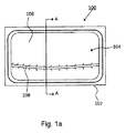
図1aを参照すると、特徴部を備えた工具の単純化された平面図が示されており、特徴部は、工具の形成面内に設けられており、この特徴部は、本発明の実施形態としてのレーザ支援工具製作方法を用いて被着されている。工具100は、形成面104を構成するよう形作られた支持本体102を有し、形成面104は、所望の形状を有する造形品を形成するよう形作られている。形成面104は、第1の部分106を有する。さらに、特徴部108が形成面104内に設けられ、この特徴部108は、形成面104の第2の部分を構成している。使用の際、特徴部108によって定められる形成面104の第1の部分106と形成面104の第2の部分は、所望の形状を備えた造形品を形成するよう協働する。例えば、工具100は、竜巻線デザイン要素を備えた自動車の車体パネルを形成するためのものである。
Referring to FIG. 1a, a simplified plan view of a tool with a feature is shown, the feature being provided in the forming surface of the tool, which feature is an embodiment of the present invention. It is applied using a laser-assisted tool manufacturing method. The
次に、図1bを参照すると、A‐A線に沿って取った図1aの工具100の単純化された断面図が示されている。図1bに示されているように、支持本体102は、第1の材料、例えば鋳鉄で作られている。支持本体102を作るための鋳鉄の使用により、高級材料、例えば工具鋼を用いて製作された工具と比較して、工具100の全体的材料費が節減される。当然のことながら、鋳鉄に代えて他の適当な材料を使用することができる。図1bに更に示されているように、支持本体102は、形成面104の所要の最終形状に近似した表面200を作るために機械加工されている。オプションとして、第1の材料は、ほぼ所要の最終形状に合わせて鋳造され、所要の最終形状を達成するために必要に応じて追加の機械加工が行われるに過ぎない。有利には、鋳鉄の硬度は、工具鋼の硬度よりも低く、したがって、支持本体102が工具鋼ではなく鋳鉄で作られている場合、表面200を機械加工するのが容易である。図示の実施形態では、鋳鉄支持本体102の機械加工面200は、形成面104の第1の部分106を構成する。オプションとして、以下に詳細に説明するように、機械加工面は、所望の材料特性を備えた別の材料で被覆される。
Referring now to FIG. 1b, a simplified cross-sectional view of the
形成面104の第2の部分を構成する図1aの特徴部108は、図1bに破線の円内に位置した状態で示されている。特徴部108の拡大断面図が図1cに示されている。次に図1b及び図1cを参照すると、特徴部108は、第1の材料で作られてはおらず、これとは異なり、特徴部108は、金属合金の複数の層から成っている。換言すると、特徴部108は、レーザ被着(クラッド)によって機械加工面200の頂部上に作られている。クラッドは、同種と異種の両方の金属を結合する方法であり、金属を互いに固定する方法として溶接又は接着とは異なっている。レーザクラッド法では、粉末状又はワイヤ供給原料をレーザの使用により溶融して圧密化する。その目的は、基板の一部を被覆し又は素形材(ニヤネットシェイプ)を製作することにある。被着させるべき材料又は材料の組み合わせを正確に選択することによって、レーザクラッド法により作られた特徴部は、所望の機械的性質を有することができる。さらに、種々の合金材料を用いることによって互いに異なる機械的性質を備えた互いに異なる特徴部を作ることができる。
The
とは言うもの、鋳鉄又は他の工具材料への工具鋼合金のレーザクラッド法は、簡単な方法ではなく、かかるレーザクラッド法の結果として、或る特定の条件下において望ましくない亀裂及び/又は気孔のあるクラッド層が形成される場合がある。クラッド層内における欠陥の形成は、鋳鉄材料と工具鋼合金の機械的及び/又は熱的性質の差並びに2種類の材料を融着させたときのこれら2つの材料相互間の適合性によるものである。本発明の実施形態としての方法では、鋳鉄又は他の適当な支持本体への金属合金の三層被着を利用して所望の機械的性質を備え、しかも望ましくない亀裂及び/又は気孔のない特徴部を作ることができる。図1b及び図1cを参照すると、3つの層は、結合層110、移行層112及び機能層114を含む。
That said, laser cladding of tool steel alloys into cast iron or other tool materials is not a simple method, and as a result of such laser cladding, cracks and / or pores are undesirable under certain conditions. In some cases, a clad layer with a thickness of 10 mm is formed. The formation of defects in the cladding layer is due to differences in the mechanical and / or thermal properties of the cast iron material and the tool steel alloy and the compatibility between the two materials when the two materials are fused. is there. The method according to an embodiment of the present invention utilizes a three-layer deposition of a metal alloy on cast iron or other suitable support body to provide the desired mechanical properties and is free of undesirable cracks and / or pores. Can make a part. Referring to FIGS. 1 b and 1 c, the three layers include a
次に、図2a〜図2dを参照すると、本発明の実施形態による工具製作方法を互いに異なる段階を示す単純化された断面図が示されている。上述したように、支持本体102を構成するために工具鋼に代えて低級材料、例えば鋳鉄を使用することができる。図2aは、機械加工面200を作るために実施された機械加工後における支持本体102の一部分を示している。特に、図2aは、特徴部108が被着されるべき機械加工表面200の一部分を示している。
Referring now to FIGS. 2a-2d, simplified cross-sectional views illustrating different stages of a tool manufacturing method according to an embodiment of the present invention are shown. As described above, a lower material such as cast iron can be used in place of the tool steel to constitute the
次に、図2bを参照すると、レーザクラッド法を用いた結合層110の非着後における支持本体102の部分が示されている。特に、結合層を支持本体102の鋳鉄又は他の材料と良好な湿潤性を示す材料で作られる。この実施例では、支持本体102が鋳鉄で作られる場合、結合層110は、例えばコバルト基合金、例えばステライト(Stellite)21で作られるのが良い。
Referring now to FIG. 2b, the portion of the
次に、図2cを参照すると、結合層110への移行層112の被着後における支持本体102の部分が示されている。この実施例では、移行層112は、中程度の硬度及び高い靱性の鉄基工具鋼合金で作られている。
Referring now to FIG. 2c, the portion of the
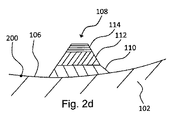
次に、図2dを参照すると、移行層112への機能層114の被着後における支持本体102の部分が示されている。特に、機能層114は、工具100の意図した用途に必要な機械的性質を提供する。この実施例では、機能層114は、所要の硬度の工具鋼合金で作られている。機能層114の被着後、機械加工が工具100を用いて製作されるべき造形品の所望の形状に基づいて工具100の形成面の形態を仕上げるために必要に応じて行われる。オプションとして、機能層114の所望の厚さを達成するために追加の機能層材料が被着される。
Referring now to FIG. 2d, the portion of the
図2a〜図2dを参照して示された方法を金属合金層がレーザクラッド法を用いて鋳鉄支持本体102に被着される特定の且つ非限定的な実施例に関して説明した。オプションとして、図2a〜図2dを参照して説明した3つの層を越えて追加の層が工具100の形成面上の特徴部108の形成中に被着されるのが良い。
The method illustrated with reference to FIGS. 2a-2d has been described with reference to a specific and non-limiting example in which a metal alloy layer is deposited on a cast
一般に、3つの金属合金層110,112,114は、支持本体102と機能層114との間に材料特性の段階的移行をもたらす。図2a〜図2dを参照して説明した方法を用いると、支持本体102の材料の機械的性質とは異なる機械的性質を備えた材料で作られた機能層114を有する特徴部を製作することができ、この場合、機能層114には亀裂及び気孔が実質的にない。機能層114は、例えば、摩耗に対して高い耐性を示す金属合金で作られる。このように、安価な材料を用いて支持本体102を形成すると共に造形品の形成中、それほど摩耗及び研磨を受けない形成面104の第1の部分106を構成することができる。造形品の形成中、相当大きな摩耗又は研磨を受ける特徴部又は領域は、図2a〜図2dを参照して説明した方法に従って肉盛りされる。かかる肉盛り特徴部の機能層114は、耐摩耗性金属合金で作られるのが良い。肉盛り特徴部は、耐摩耗性が非常に高く、しかも形成面104の他の部分は、それほど大きな摩耗又は研磨を受けないと言えるので、上述した方法に従って製作される工具の全体的寿命は、全体が高級材料で製作された工具の寿命と同等であると言える。したがって、図2a〜図2dを参照して説明した方法は、材料費を安くしかも機械加工費を安くした状態での工具の製作を支援するが、工具の寿命を犠牲にすることはなく、しかも工具の寿命中、大がかりな追加の保守を必要としない。
In general, the three metal alloy layers 110, 112, 114 provide a gradual transition of material properties between the
次に、図3aを参照すると、図2a〜図2dを参照して説明した方法の変形例に従って製作された工具の形成面の一部分の拡大断面図が示されている。加うるに、図3bは、図3aの破線の円で囲んだ構造体の拡大細部を示している。具体的に言えば、特徴部108は、実質的に図2a〜図2dを参照して上述したように支持本体102の機械加工面200上に形成されている。加うるに、第2の特徴部300が特徴部108に隣接して位置する機械加工面200の部分に被着されている。この実施例では、第2の特徴部300は、3つの金属合金層を含む薄い表面被膜の形態で被着され、かかる3つの金属合金層は、支持本体102の材料と良好な湿潤性を示す第1の金属合金で作られた結合層302、第2の金属合金で作られた軸方向304及び所望の機械的性質を有する第3の金属合金で作られた機能層306を含む。例えば、第2の特徴部300は、特徴部108に隣接して位置する工具の形成面の部分と比較して高い耐摩耗性を提供するために被着される。オプションとして、第2の特徴部300は、工具の実質的に形成面全体にわたって延び、又は、第2の特徴部300は、工具を用いた造形品の形成中、高度の摩耗及び研磨作用を受けることが見込まれる形成面の選択された部分のみについて延びる。この実施例では、特徴部300及び特徴部108は、工具の形成面の連続して並んだ表面部分を構成する。
Referring now to FIG. 3a, there is shown an enlarged cross-sectional view of a portion of the forming surface of a tool made in accordance with a variation of the method described with reference to FIGS. 2a-2d. In addition, FIG. 3b shows an enlarged detail of the structure enclosed by the dashed circle in FIG. 3a. Specifically, the
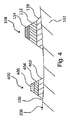
次に、図4を参照すると、図2a〜図2dを参照して説明した方法の別の変形例に従って製作された工具の形成面の一部分の拡大断面図が示されている。具体的に言えば、特徴部108は、図2a〜図2dを参照して実質的に上述した支持本体102の機械加工面200上に形成されている。加うるに、第2の特徴部400が特徴部108に隣接し且つこれから間隔を置いた状態で機械加工面200の一部分に被着されている。第2の特徴部400は、特徴部108と実質的に同じであり、第2の特徴部400は、支持本体102の材料と良好な湿潤性を示す第1の金属合金で作られた結合層402、第2の金属合金で作られた移行層404及び所望の機械的性質を有する第3の金属合金で作られた機能層406を含む。第2の特徴部400は、工具102の形成面の第3の部分を形成する。この実施例では、特徴部108及び第2の特徴部400は、工具102の形成面の連続して並んでいない部分を構成する。とは言うものの、形成面106の第1の部分は、特徴部108と第2の特徴部400の両方によって構成された形成面と連続して位置している。さらに、この実施例では、第2の特徴部400の機能層406と特徴部108の機能層114は、互いに異なる合金で作られている。例えば、機能層406は、特徴部108の機能層を形成するために用いられている材料よりも高い耐摩耗性を有する工具鋼合金で作られている。この実施例では、特徴部108,400のそれぞれの結合層110,402は、同種の金属合金で作られ、特徴部108,400のそれぞれの移行層112,404は、同種の金属合金で作られている。オプションとして、特徴部108,400のそれぞれの結合層及び/又は移行層は、互いに異なる合金で作られる。例えば、互いに異なる金属合金は、冶金学的適合性を保証するために選択される。
Referring now to FIG. 4, there is shown an enlarged cross-sectional view of a portion of a forming surface of a tool made in accordance with another variation of the method described with reference to FIGS. 2a-2d. Specifically, the
図1〜図4を参照して説明した実施形態では、機能層の材料は、支持ベースの材料と冶金学的に適合性がある。例えば、機能層の材料は、鉄基工具鋼合金であり、支持ベースの金属は、鋳鉄である。それにもかかわらず、冶金学的に適合性があるとは言え、機能層は、これがレーザクラッド法を用いて支持本体102に直接被着された場合亀裂及び望ましくない気孔を含むことになると予想される。この場合における不適合性は、材料特性の差によるものであり、例えば、工具鋼機能層の硬度は、この特定の且つ非限定的な実施例では、鋳鉄支持本体の硬度よりも極めて高い。結合層及び移行層は、支持本体102と機能層114との間の材料特性の段階的移行を提供し、それにより亀裂及び望ましくない気孔が実質的にない機能層114の形成を可能にするよう機能層114の被着に先立って支持本体102に被着される。
In the embodiment described with reference to FIGS. 1-4, the functional layer material is metallurgically compatible with the support base material. For example, the functional layer material is an iron-based tool steel alloy, and the support base metal is cast iron. Nevertheless, although functionally compatible, the functional layer is expected to contain cracks and undesirable pores when it is applied directly to the
他のシステムでは、機能層の材料は、支持本体の材料と冶金学的に不適合である場合がある。上述した同じ方法は、冶金学的に不適合な材料を含む構造体を形成するのにも利用できる。例えば、結合層の材料は、支持ベースの材料と冶金学的に適合性があるよう選択され、移行層の材料は、結合層の材料と機能層の材料の両方と冶金学的に適合性があるように選択される。このように、レーザクラッド法を利用すると、所望の結合層支持本体に被着させ、次いで所望の移行層を結合層に被着させることができ、次いで機能層を移行層に被着させることができる。互いに異なる層の各々について材料の適切な選択を行うことにより、機能層の材料が支持ベースの材料と冶金学的に不適合である場合であっても実質的に望ましくない亀裂及び望ましくない気孔のない機能層を形成することができる。 In other systems, the functional layer material may be metallurgically incompatible with the support body material. The same method described above can also be used to form structures containing metallurgically incompatible materials. For example, the tie layer material is selected to be metallurgically compatible with the support base material, and the transition layer material is metallurgically compatible with both the tie layer material and the functional layer material. Selected to be. Thus, using the laser cladding method, a desired tie layer support body can be deposited, then a desired transition layer can be deposited on the tie layer, and then a functional layer can be deposited on the transition layer. it can. By making an appropriate selection of materials for each of the different layers, there is substantially no undesirable cracking and undesirable porosity even when the functional layer material is metallurgically incompatible with the support base material. A functional layer can be formed.
次に、図5を参照すると、本発明の実施形態に従って工具を製作する方法の単純化された流れ図が示されている。ステップ500では、第1の材料から二次加工された支持本体を用意する。例えば、第1の材料は、工具鋼よりも低い等級のものであって良く、例えば、鋳鉄である。オプションとして、支持本体を所望の最終形状にほぼ合わせて鋳造され、又は、支持本体は、ブロックの形態で用意される。ステップ502では、第1の材料の一部分を支持本体から機械加工して工具の形成面の第1の部分を構成する。必要な機械加工の量は、支持本体がほぼ所望の最終形状に合わせて鋳造されるかどうか又はブロックの形態で提供されるかどうかで決まる。ステップ504では、工具の形成面の第2の部分を構成する特徴部を支持本体に被着させる。具体的に説明すると、特徴部の被着では、第2の材料の層を支持本体の第1の材料の層に被着させ、次に第3の材料の層を第2の材料の層に被着させ、最後に第4の材料を第3の材料の層に被着させる。被着されている材料を粉末かワイヤ供給原料かのいずれかの形態で供給し、この材料をレーザを用いて溶融し、そして基材の所望の部分に被着させる。層の各々被着では、オプションとして、それぞれの材料の多数の層を被着させて被着材料の所望の厚さを達成する。オプションとして、結合層、移行層及び機能層は、互いに異なる厚さのものである。ステップ506では、必要に応じて追加の機械加工を実施して特徴部の所望の最終形状を得ると共に形成面を仕上げする。使用中、第4の材料の層は、工具の形成面の第2の部分を構成し、この第2の部分は、所望の形状を有する造形品を製作するよう工具の形成面の第1の部分と協働する。
Referring now to FIG. 5, a simplified flow diagram of a method for making a tool according to an embodiment of the present invention is shown. In
次に、図6を参照すると、本発明の実施形態に従って工具を補修する方法の単純化された流れ図が示されている。具体的に言えば、この方法は、工具中の欠陥を補修するための方法であり、工具は、第1の材料から二次加工された支持本体を有すると共に支持本体に被着された第1の金属合金層、第1の金属合金層に被着された第2の金属合金層及び第2の金属合金層に被着された第3の金属合金層を含む特徴部を有する。この特定の且つ非限定的な実施例では、第3の金属合金の追加の層が三層特徴部の頂部に被着され、その結果、第3の金属合金層の材料の厚さが第3の金属合金層内で欠陥及び/又は摩耗が生じるようにするのに十分であることが想定される。とは言うものの、幾つかの場合、欠陥又は摩耗は、下に位置する層、例えば第2の金属合金層又はそれどころか第1の金属合金層中に及ぶ場合のあることが考えられる。 Referring now to FIG. 6, a simplified flow diagram of a method for repairing a tool according to an embodiment of the present invention is shown. Specifically, this method is a method for repairing a defect in a tool, the tool having a support body that has been second-machined from a first material and being attached to the support body. A metal alloy layer, a second metal alloy layer deposited on the first metal alloy layer, and a third metal alloy layer deposited on the second metal alloy layer. In this particular and non-limiting example, an additional layer of a third metal alloy is deposited on top of the three-layer feature so that the material thickness of the third metal alloy layer is the third It is envisaged that it is sufficient to cause defects and / or wear in the metal alloy layer. Nevertheless, in some cases it is conceivable that defects or wear may extend into the underlying layer, for example the second metal alloy layer or even the first metal alloy layer.
依然として図6を参照すると、ステップ600では、欠陥を含む第3の金属合金層の少なくとも一部分を除去する。例えば、第3の金属合金層を機械加工して第3の金属合金のうちの少なくとも何割かを除去する。オプションとして、第3の金属合金層を全て除去する。ステップ602では、除去した第3の金属合金層の少なくとも一部分に取って代わるよう或る量の第3の金属合金を被着させる。具体的に言えば、レーザクラッド法を用いて第3の金属合金を被着させ、それにより、第3の金属合金は、粉末かワイヤ供給原料かのいずれかの形態で供給され、レーザを用いて溶融し、そして除去した第3の金属合金層の少なくとも一部分に取って代わるようにする。被着させる第3の金属合金の量は、補修中の特徴部の設計上の寸法を超えるのに十分である。その後、ステップ604において、被着させた第3の金属合金を機械加工して特徴部の実質的に設計上の寸法を達成し、設計上の寸法は、工具を用いて製造される造形品の所望の形状に基づいて定められる。
Still referring to FIG. 6,
次に図7を参照すると、本発明の実施形態に従って工具の使用目的を変更する方法の単純化された流れ図が示されている。具体的に説明すると、図7の方法は、例えば、形成面内に特徴部を設けることによって既存の工具の形成面の修正に関する。オプションとして、例えば機械加工において1つ又は2つ以上の既存の特徴部を除去し又は修正する。ステップ700では、工具を用意し、工具は、第1の形態を備えた形成面を有する既存の工具であり、工具は、第1の材料で作られている。例えば、第1の材料は、工具鋼よりも低い等級のものであり、例えば、鋳鉄である。ステップ702では、レーザクラッド法を利用して特徴部を工具の形成面に被着させる。特徴部の被着ステップは、第2の材料の層を工具の第1の材料の層に被着させるステップ、第3の材料の層を第2の材料の層に被着させるステップ及び第4の材料の層を第3の材料の層に被着させるステップを含む。ステップ704では、追加の機械加工を実施して形成面の所望の第2の形態を達成する。第4の材料の層は、工具の形成面の一部分を構成する。さらに、形成面の既存の特徴部の場所に一致している部分以外の形成面の一部分に特徴部を被着させ、その結果、形成面の第2の形態が特徴部の被着後において第1の形態とは異なるようにする。
Referring now to FIG. 7, a simplified flow diagram of a method for changing the intended use of a tool according to an embodiment of the present invention is shown. Specifically, the method of FIG. 7 relates to the modification of the forming surface of an existing tool, for example, by providing a feature in the forming surface. Optionally, one or more existing features are removed or modified, for example in machining. In
支持本体について低級材料、例えば鋳鉄を用いると共にレーザクラッド法を利用して特徴部を製作することによって、初期の工具製作費が先行技術の工具製作プロセスと比較して減少する。特徴部の製作に適当な材料を選択することによって、特定の要素について所望の機械的性質を備えたクラッドを作ることができる。特に、摩耗及び研磨を受ける特徴部の長い有効寿命を保証した状態で工具を製作することができる。欠陥又は摩耗が検出されると、工具を再生利用するのではなく品質を損なわないで補修することができる。かかる補修は、任意の熱処理又は大規模な機械加工を行わないで実施可能であり、それにより時間、エネルギー及び費用が節減される。幾つかの場合、完全に新品の工具を製作するのではなく既存の工具の特徴部を修正することが可能な場合があり、それにより旧式の工具を再生利用するのではなくその使用目的を変更できることが可能な場合がある。 By using lower materials such as cast iron for the support body and fabricating the features using the laser cladding method, the initial tool fabrication costs are reduced compared to prior art tool fabrication processes. By selecting the appropriate material for the fabrication of the feature, a cladding with the desired mechanical properties for a particular element can be made. In particular, the tool can be manufactured with a guaranteed long useful life of the features subject to wear and polishing. If a defect or wear is detected, the tool can be repaired without loss of quality rather than being recycled. Such repairs can be performed without any heat treatment or extensive machining, thereby saving time, energy and cost. In some cases, it may be possible to modify the features of an existing tool rather than making a completely new tool, thereby changing the purpose of the old tool rather than reusing it It may be possible.
上述の説明は、本発明の複数の実施形態に関するが、理解されるように、本発明は、添付の特許請求の範囲の記載の公正な意味から逸脱することなく別の改造及び変更が可能である。 Although the foregoing description relates to a plurality of embodiments of the present invention, it will be understood that the invention is capable of other modifications and changes without departing from the fair meaning of the appended claims. is there.
Claims (15)
前記工具の形成面の第1の部分を構成する機械加工面を備えた支持本体と、
前記機械加工面に隣接して前記支持本体上に支持されると共に前記形成面の第2の部分を構成する特徴部とを有し、前記特徴部は、前記支持本体の前記機械加工面の材料と冶金学的に不適合性を示す材料で作られた頂部層、前記支持本体の前記機械加工面の前記材料と冶金学的に適合性のある材料で作られた底部層及び前記頂部層の前記材料及び前記底部層の前記材料と冶金学的に適合性のある材料で作られた中間層を含み、使用の際、前記形成面の前記第1の部分と前記形成面の前記第2の部分は、前記造形品の所望の形状を形成するよう協働する、工具。 A tool for forming a shaped article, wherein the tool is
A support body comprising a machined surface forming a first part of the forming surface of the tool;
And a feature that is supported on the support body adjacent to the machining surface and that constitutes a second portion of the forming surface, wherein the feature is a material of the machining surface of the support body. A top layer made of a metallurgically incompatible material, a bottom layer made of a material metallurgically compatible with the material of the machined surface of the support body, and the top layer An intermediate layer made of a material and a material that is metallurgically compatible with the material of the bottom layer, and in use, the first portion of the forming surface and the second portion of the forming surface Is a tool that cooperates to form the desired shape of the shaped article.
前記工具は、更に、第2の特徴部を有し、前記第2の特徴部は、第1の材料上に支持された結合層を構成するよう互いに上下に被着された金属合金の複数の層、前記結合層上に支持された移行層及び前記移行層上に支持された機能層を含み、
前記第1の特徴部の前記機能層は、第1の材料特性を備えた第1の金属合金から二次加工され、前記第2の特徴部の前記機能層は、第2の材料特性を備えた第2の金属合金から二次加工され、前記第2の材料特性は、前記第1の材料特性とは異なる、請求項1に記載の工具。 The feature is a first feature, the bottom layer is a tie layer supported on the material of the machined surface, and the intermediate layer is a transition layer supported on the tie layer. The top layer is a functional layer supported on the transition layer,
The tool further includes a second feature, wherein the second feature is a plurality of metal alloys that are deposited one above the other to form a tie layer supported on the first material . A transition layer supported on the binding layer and a functional layer supported on the transition layer,
The functional layer of the first feature is secondary processed from a first metal alloy having a first material property, and the functional layer of the second feature has a second material property. The tool according to claim 1, wherein the tool is second processed from a second metal alloy, and wherein the second material property is different from the first material property.
第1の材料から二次加工された支持本体を用意するステップと、
前記支持本体から前記第1の材料の一部分を機械加工して前記工具の形成面の第1の部分を構成するステップと、
前記工具の前記形成面の第2の部分を構成する特徴部を前記支持本体上に被着させるステップとを含み、前記被着ステップは、
第2の材料の層を前記支持本体の前記第1の材料上に被着させるステップと、
第3の材料の層を前記第2の材料層に被着させるステップと、
第4の材料の層を前記第3の材料層に被着させるステップとを含み、前記第4の材料層は、前記工具の前記形成面の第2の部分を構成し、
前記第2の材料は、前記第1の材料と冶金学的に適合性があり、前記第4の材料は、前記第1の材料と冶金学的に不適合性を示し、前記第3の材料は、前記第2の材料と前記第4の材料の両方と冶金学的に適合性がある、方法。 A method of making a tool,
Providing a support body secondary processed from a first material;
Machining a portion of the first material from the support body to form a first portion of the forming surface of the tool;
Depositing on the support body a feature that constitutes a second portion of the forming surface of the tool, the depositing step comprising:
Depositing a layer of a second material on the first material of the support body;
Depositing a layer of a third material on the second material layer;
Depositing a fourth material layer on the third material layer, wherein the fourth material layer constitutes a second portion of the forming surface of the tool;
The second material is metallurgically compatible with the first material, the fourth material is metallurgically incompatible with the first material, and the third material is A method that is metallurgically compatible with both the second material and the fourth material.
第1の形態を備えた形成面を有する工具を用意するステップを含み、前記工具は、第1の材料から二次加工され、
レーザクラッド法を利用して特徴部を前記工具の前記形成面に被着させるステップを含み、前記被着ステップは、
第2の材料の層を前記工具の前記第1の材料上に被着させるステップと、
第3の材料の層を前記第2の材料層に被着させるステップと、
第4の材料の層を前記第3の材料層に被着させるステップとを含み、前記第4の材料層は、前記工具の前記形成面の第2の部分を構成し、
前記特徴部は、前記形成面の既存の特徴部の場所に相当していない前記形成面の一部分に被着され、その結果、前記形成面は、前記特徴部の被着後、前記第1の形態とは異なる第2の形態を有する、方法。 A method for changing the purpose of use of a tool,
Providing a tool having a forming surface with a first configuration, the tool being secondary processed from a first material;
Applying a feature to the forming surface of the tool using a laser cladding method, the applying step comprising:
Depositing a layer of a second material on the first material of the tool ;
Depositing a layer of a third material on the second material layer;
Depositing a fourth material layer on the third material layer, wherein the fourth material layer constitutes a second portion of the forming surface of the tool;
The feature is deposited on a portion of the forming surface that does not correspond to the location of an existing feature on the forming surface, so that the forming surface is the first after the feature is deposited. A method having a second form different from the form.
Applications Claiming Priority (3)
| Application Number | Priority Date | Filing Date | Title |
|---|---|---|---|
| US201261624562P | 2012-04-16 | 2012-04-16 | |
| US61/624,562 | 2012-04-16 | ||
| PCT/CA2013/000321 WO2013155591A1 (en) | 2012-04-16 | 2013-04-04 | Process for laser-assisted tool build and repair |
Publications (3)
| Publication Number | Publication Date |
|---|---|
| JP2015517915A JP2015517915A (en) | 2015-06-25 |
| JP2015517915A5 JP2015517915A5 (en) | 2016-04-21 |
| JP6162217B2 true JP6162217B2 (en) | 2017-07-12 |
Family
ID=49382735
Family Applications (1)
| Application Number | Title | Priority Date | Filing Date |
|---|---|---|---|
| JP2015506050A Active JP6162217B2 (en) | 2012-04-16 | 2013-04-04 | Laser support tool production and repair method |
Country Status (5)
| Country | Link |
|---|---|
| US (2) | US9764425B2 (en) |
| EP (1) | EP2838691A4 (en) |
| JP (1) | JP6162217B2 (en) |
| CN (1) | CN104245224B (en) |
| WO (1) | WO2013155591A1 (en) |
Families Citing this family (6)
| Publication number | Priority date | Publication date | Assignee | Title |
|---|---|---|---|---|
| CA3024357C (en) * | 2016-05-27 | 2023-01-03 | Husky Injection Molding Systems Ltd. | Mold gate structures |
| US11148199B2 (en) * | 2016-07-29 | 2021-10-19 | Tesla, Inc. | Deposition of metal dies for part fabrication |
| CN110814633B (en) * | 2019-10-30 | 2021-01-05 | 山东成通锻造有限公司 | Welding repair process for large-scale column nest and column cap mold |
| US11767905B2 (en) | 2020-08-07 | 2023-09-26 | Ami Industries, Inc. | Laminated rack assembly for powered motion of aircraft seats |
| CN113235086A (en) * | 2021-05-11 | 2021-08-10 | 重庆工港致慧增材制造技术研究院有限公司 | Surface repairing method for air valve for ship engine |
| CN117102512B (en) * | 2023-09-15 | 2024-02-06 | 华中科技大学 | Laser composite additive manufacturing device and manufacturing method for double alloy parts |
Family Cites Families (17)
| Publication number | Priority date | Publication date | Assignee | Title |
|---|---|---|---|---|
| JPS59197320A (en) * | 1983-04-26 | 1984-11-08 | Nissan Motor Co Ltd | Manufacture of die |
| JPS59223167A (en) * | 1983-06-02 | 1984-12-14 | Mitsubishi Electric Corp | Manufacture of metallic die for press work |
| JPS62101392A (en) * | 1985-10-29 | 1987-05-11 | Toyota Motor Corp | Filling method for cast iron material utilizing high density energy source |
| US5837960A (en) * | 1995-08-14 | 1998-11-17 | The Regents Of The University Of California | Laser production of articles from powders |
| CN1071168C (en) * | 1996-02-15 | 2001-09-19 | 贝尔纳国际公司 | Cutting die and method of forming |
| US6122564A (en) * | 1998-06-30 | 2000-09-19 | Koch; Justin | Apparatus and methods for monitoring and controlling multi-layer laser cladding |
| US6472029B1 (en) * | 1998-06-30 | 2002-10-29 | The P.O.M. Group | Fabrication of laminate structures using direct metal deposition |
| US6391251B1 (en) * | 1999-07-07 | 2002-05-21 | Optomec Design Company | Forming structures from CAD solid models |
| JP4517099B2 (en) * | 2000-02-22 | 2010-08-04 | 本田技研工業株式会社 | Mold |
| US6447704B1 (en) * | 2000-05-23 | 2002-09-10 | Gmic, Corp. | Thermal-sprayed tooling |
| JP4313975B2 (en) * | 2002-02-22 | 2009-08-12 | 新日本製鐵株式会社 | Die for plate pressing in warm or hot |
| US20060006157A1 (en) * | 2004-07-09 | 2006-01-12 | Ingersoll Machine Tools, Inc. | Method and apparatus for repairing or building up surfaces on a workpiece while the workpiece is mounted on a machine tool |
| DE102005031584A1 (en) * | 2005-07-06 | 2007-01-11 | Mtu Aero Engines Gmbh | Method for producing a composite component |
| US20090308847A1 (en) * | 2006-08-02 | 2009-12-17 | Kabushiki Kaisha Toshiba | Erosion prevention method and member with erosion preventive section |
| EP2072205A1 (en) | 2007-12-17 | 2009-06-24 | Rovalma SA | Method for producing highly mechanically demanded pieces and specially tools from low cost ceramics or polymers |
| WO2009090622A1 (en) | 2008-01-18 | 2009-07-23 | Mould Technico Cc | A method of extending the lifespan of a metal cavity mould |
| CN202052935U (en) * | 2011-04-15 | 2011-11-30 | 华中科技大学 | Laser-induction hybrid melting direct-forming device |
-
2013
- 2013-04-04 US US14/394,659 patent/US9764425B2/en active Active
- 2013-04-04 JP JP2015506050A patent/JP6162217B2/en active Active
- 2013-04-04 WO PCT/CA2013/000321 patent/WO2013155591A1/en active Application Filing
- 2013-04-04 EP EP13778443.5A patent/EP2838691A4/en active Pending
- 2013-04-04 CN CN201380020171.4A patent/CN104245224B/en active Active
-
2017
- 2017-08-15 US US15/677,525 patent/US10456866B2/en active Active
Also Published As
| Publication number | Publication date |
|---|---|
| JP2015517915A (en) | 2015-06-25 |
| US20150089992A1 (en) | 2015-04-02 |
| EP2838691A4 (en) | 2016-01-13 |
| CN104245224A (en) | 2014-12-24 |
| EP2838691A1 (en) | 2015-02-25 |
| WO2013155591A1 (en) | 2013-10-24 |
| US20170341181A1 (en) | 2017-11-30 |
| CN104245224B (en) | 2017-11-10 |
| US10456866B2 (en) | 2019-10-29 |
| US9764425B2 (en) | 2017-09-19 |
Similar Documents
| Publication | Publication Date | Title |
|---|---|---|
| US10456866B2 (en) | Process for laser-assisted tool build and repair | |
| JP6548462B2 (en) | Additional manufacturing method | |
| CA3011483C (en) | Methods for producing additively manufactured products | |
| CN109093048B (en) | Large-scale machine brake type forging die and forging method | |
| CA3011463C (en) | Methods for producing forged products and other worked products | |
| KR20160147860A (en) | Method for the production of parts made from metal or metal matrix composite and resulting from additive manufacturing followed by an operation involving the forging of said parts | |
| CN109941358B (en) | Method for applying a reinforcement of a metallic material to a member of a metallic material | |
| JP2019531897A5 (en) | ||
| JP2015517915A5 (en) | ||
| US9375778B2 (en) | Method for forming forged parts | |
| CN104894557B (en) | A kind of metal die composite forming method | |
| KR20150042632A (en) | Manufacturing method of metal sheet using 3D-printing and the metal sheet | |
| CN105483695A (en) | Manufacturing method for furnace bottom roller | |
| JP2009285671A (en) | Forged wheel made of light alloy and its manufacturing method | |
| JP5457903B2 (en) | Manufacturing method of press-formed products made of light alloy materials | |
| JP5272245B2 (en) | Drawing press type bead processing method | |
| CN204267122U (en) | For the extremity piece of camshaft | |
| GB2550345A (en) | Component manufacturing | |
| FR2981001A1 (en) | Method for manufacturing three-dimensional composite material e.g. aeronautical structural part, involves stamping preform to provide desired form, and cooling stamped preform by maintaining stamped preform under pressure along with blank | |
| JP2004255400A (en) | Aluminum alloy difference thickness blank material manufacturing method | |
| US20220097139A1 (en) | Method for the production of parts made from metal or metal matrix composite and resulting from additive manufacturing followed by an operation involving the forging of said parts | |
| US20200261964A1 (en) | Method For Producing A Structural Component From A High-Strength Alloy Material |
Legal Events
| Date | Code | Title | Description |
|---|---|---|---|
| A521 | Request for written amendment filed |
Free format text: JAPANESE INTERMEDIATE CODE: A523 Effective date: 20160225 |
|
| A621 | Written request for application examination |
Free format text: JAPANESE INTERMEDIATE CODE: A621 Effective date: 20160225 |
|
| A977 | Report on retrieval |
Free format text: JAPANESE INTERMEDIATE CODE: A971007 Effective date: 20170112 |
|
| A131 | Notification of reasons for refusal |
Free format text: JAPANESE INTERMEDIATE CODE: A131 Effective date: 20170206 |
|
| RD04 | Notification of resignation of power of attorney |
Free format text: JAPANESE INTERMEDIATE CODE: A7424 Effective date: 20170414 |
|
| A521 | Request for written amendment filed |
Free format text: JAPANESE INTERMEDIATE CODE: A523 Effective date: 20170428 |
|
| TRDD | Decision of grant or rejection written | ||
| A01 | Written decision to grant a patent or to grant a registration (utility model) |
Free format text: JAPANESE INTERMEDIATE CODE: A01 Effective date: 20170515 |
|
| A61 | First payment of annual fees (during grant procedure) |
Free format text: JAPANESE INTERMEDIATE CODE: A61 Effective date: 20170614 |
|
| R150 | Certificate of patent or registration of utility model |
Ref document number: 6162217 Country of ref document: JP Free format text: JAPANESE INTERMEDIATE CODE: R150 |
|
| R250 | Receipt of annual fees |
Free format text: JAPANESE INTERMEDIATE CODE: R250 |
|
| R250 | Receipt of annual fees |
Free format text: JAPANESE INTERMEDIATE CODE: R250 |
|
| R250 | Receipt of annual fees |
Free format text: JAPANESE INTERMEDIATE CODE: R250 |
|
| R250 | Receipt of annual fees |
Free format text: JAPANESE INTERMEDIATE CODE: R250 |