JP6158625B2 - motor - Google Patents
motor Download PDFInfo
- Publication number
- JP6158625B2 JP6158625B2 JP2013155450A JP2013155450A JP6158625B2 JP 6158625 B2 JP6158625 B2 JP 6158625B2 JP 2013155450 A JP2013155450 A JP 2013155450A JP 2013155450 A JP2013155450 A JP 2013155450A JP 6158625 B2 JP6158625 B2 JP 6158625B2
- Authority
- JP
- Japan
- Prior art keywords
- terminal housing
- locking
- motor according
- motor
- locking member
- Prior art date
- Legal status (The legal status is an assumption and is not a legal conclusion. Google has not performed a legal analysis and makes no representation as to the accuracy of the status listed.)
- Active
Links
- 230000008878 coupling Effects 0.000 claims description 25
- 238000010168 coupling process Methods 0.000 claims description 25
- 238000005859 coupling reaction Methods 0.000 claims description 25
- 239000012212 insulator Substances 0.000 claims description 23
- 238000003780 insertion Methods 0.000 claims description 7
- 230000037431 insertion Effects 0.000 claims description 7
- 230000002093 peripheral effect Effects 0.000 claims description 5
- 230000001105 regulatory effect Effects 0.000 claims 1
- 230000005540 biological transmission Effects 0.000 description 11
- 230000009977 dual effect Effects 0.000 description 7
- 239000000463 material Substances 0.000 description 5
- 238000000034 method Methods 0.000 description 4
- 230000008569 process Effects 0.000 description 4
- 229910000976 Electrical steel Inorganic materials 0.000 description 2
- 229920005989 resin Polymers 0.000 description 2
- 239000011347 resin Substances 0.000 description 2
- 230000015572 biosynthetic process Effects 0.000 description 1
- 230000008859 change Effects 0.000 description 1
- 239000004020 conductor Substances 0.000 description 1
- 230000003247 decreasing effect Effects 0.000 description 1
- 230000007547 defect Effects 0.000 description 1
- 230000005611 electricity Effects 0.000 description 1
- 230000004907 flux Effects 0.000 description 1
- 239000000446 fuel Substances 0.000 description 1
- 239000011810 insulating material Substances 0.000 description 1
- 238000010030 laminating Methods 0.000 description 1
- 230000007246 mechanism Effects 0.000 description 1
- 238000012986 modification Methods 0.000 description 1
- 230000004048 modification Effects 0.000 description 1
- 238000004080 punching Methods 0.000 description 1
- 229920003002 synthetic resin Polymers 0.000 description 1
- 239000000057 synthetic resin Substances 0.000 description 1
- 238000004804 winding Methods 0.000 description 1
Images


Classifications
-
- H—ELECTRICITY
- H02—GENERATION; CONVERSION OR DISTRIBUTION OF ELECTRIC POWER
- H02K—DYNAMO-ELECTRIC MACHINES
- H02K5/00—Casings; Enclosures; Supports
- H02K5/04—Casings or enclosures characterised by the shape, form or construction thereof
- H02K5/22—Auxiliary parts of casings not covered by groups H02K5/06-H02K5/20, e.g. shaped to form connection boxes or terminal boxes
- H02K5/225—Terminal boxes or connection arrangements
-
- H—ELECTRICITY
- H02—GENERATION; CONVERSION OR DISTRIBUTION OF ELECTRIC POWER
- H02K—DYNAMO-ELECTRIC MACHINES
- H02K3/00—Details of windings
- H02K3/46—Fastening of windings on the stator or rotor structure
- H02K3/52—Fastening salient pole windings or connections thereto
- H02K3/521—Fastening salient pole windings or connections thereto applicable to stators only
- H02K3/522—Fastening salient pole windings or connections thereto applicable to stators only for generally annular cores with salient poles
-
- H—ELECTRICITY
- H02—GENERATION; CONVERSION OR DISTRIBUTION OF ELECTRIC POWER
- H02K—DYNAMO-ELECTRIC MACHINES
- H02K2213/00—Specific aspects, not otherwise provided for and not covered by codes H02K2201/00 - H02K2211/00
- H02K2213/03—Machines characterised by numerical values, ranges, mathematical expressions or similar information
Landscapes
- Engineering & Computer Science (AREA)
- Power Engineering (AREA)
- Motor Or Generator Frames (AREA)
- Insulation, Fastening Of Motor, Generator Windings (AREA)
- Connector Housings Or Holding Contact Members (AREA)
Description
本発明は、自動車用モータに関するものである。 The present invention relates to an automobile motor.
一般に、BLDC(Brushless DC)モータは、DCモータにおいてブラシと整流子が必要なく、電子的な整流機構を設置したモータであって、機械的なノイズだけでなく電気的なノイズも発生しない長所を有するモータである。 In general, a BLDC (Brushless DC) motor does not require a brush and a commutator in a DC motor, and has an electronic commutation mechanism, and does not generate mechanical noise as well as electrical noise. It is a motor having.
従来のBLDCモータは、モータハウジングやフレームなどに装着されるステーター(stator)と、ステーターの内部に回転可能に挿入されるマグネットローター(magnet rotor)と、ローターの中心部に挿入されて固定される軸とを有する。 A conventional BLDC motor is inserted and fixed in a stator mounted on a motor housing or a frame, a magnet rotor that is rotatably inserted into the stator, and a central portion of the rotor. And a shaft.
ステーターは、ステーターコアにコイルが巻取されている。ステーターコアは、1mm以内の珪素鋼板をプレスでパンチングした後、積層して製作されるものであって、各々の珪素鋼板は、円筒状に形成されたヨーク部と、該ヨーク部の内周面に円周方向に沿って一定の間隔を置いて中心に向かって突出する複数の歯部と、該歯部の先端に両側に突出して極性を帯びるポール部とからなる。 The stator has a coil wound around a stator core. The stator core is manufactured by punching a silicon steel plate of 1 mm or less with a press and then laminating, and each silicon steel plate has a yoke portion formed in a cylindrical shape and an inner peripheral surface of the yoke portion. And a plurality of tooth portions projecting toward the center at regular intervals along the circumferential direction, and pole portions projecting on both sides at the tips of the tooth portions.
歯部の間にはコイルが巻かれる複数のスロットが形成され、スロットには、ステーターコアとコイルとの間を絶縁するように絶縁物質からなるインシュレーター(insulator)が挿入されている。インシュレーターは、ステーターコアの積層方向に沿って両側で各々密封されて挿入されるように結合されている。一方、コイルは、使用される電源の極性に対応するように巻線できるが、3相(U、V、W)電源を用いる場合、3極性の互いに異なるターミナルと通電可能に連結される。 A plurality of slots around which coils are wound are formed between the teeth, and an insulator made of an insulating material is inserted into the slots so as to insulate between the stator core and the coils. The insulators are joined so as to be sealed and inserted on both sides along the stacking direction of the stator core. On the other hand, the coil can be wound so as to correspond to the polarity of the power source used, but when a three-phase (U, V, W) power source is used, it is connected to terminals having different three polarities so as to be energized.
インシュレーターにはターミナルハウジング結合部が一体に設けられ、電源供給のためのターミナルハウジングがターミナルハウジング結合部に嵌合されて結合される。一般に、ターミナルハウジングとインシュレーターは、合成樹脂材質で射出成形されるが、組立後にターミナルハウジング結合部とターミナルハウジングとの間の遊隔が大きく形成されて、電源印加位置の組立時にターミナルハウジングが離脱し易くなる問題がある。 The insulator is integrally provided with a terminal housing coupling portion, and a terminal housing for supplying power is fitted and coupled to the terminal housing coupling portion. In general, the terminal housing and the insulator are injection-molded with a synthetic resin material. After assembly, a large clearance is formed between the terminal housing coupling portion and the terminal housing, and the terminal housing is detached when the power supply position is assembled. There is a problem that becomes easy.
本発明の目的は、モータの組立時にターミナルハウジングが電源供給端子と正確に組立できるように構造が改善されたモータのターミナル連結構造を提供することである。 An object of the present invention is to provide a motor terminal connection structure with an improved structure so that a terminal housing can be accurately assembled with a power supply terminal when the motor is assembled.
本発明に係るモータは、互いに異なる極性の電源が印加される複数のコイルが巻線されるステーターコアと結合され、前記コイルとステーターコアのショートを防止するインシュレーター本体と、前記インシュレーター本体と一体に構成され、円周方向に突出して外部電源を供給するターミナルハウジングが結合されるターミナルハウジング結合部と、モータに電源を供給できるように、前記ターミナルハウジング結合部に結合されるターミナルハウジングと、前記ターミナルハウジング結合部に前記ターミナルハウジングを位置固定する固定ユニットと、前記ターミナルハウジングの回転角度を規制する、前記固定ユニット上の規制ユニットと、を含む。 The motor according to the present invention is coupled to a stator core around which a plurality of coils to which power of different polarities are applied is wound, and an insulator body that prevents a short circuit between the coil and the stator core; and the insulator body A terminal housing coupling portion configured to be coupled to a terminal housing configured to project in a circumferential direction and supplying an external power source; a terminal housing coupled to the terminal housing coupling portion so as to supply power to the motor; and the terminal A fixing unit for fixing the position of the terminal housing to the housing coupling portion; and a restriction unit on the fixing unit for restricting a rotation angle of the terminal housing.
前記固定ユニットは、前記ターミナルハウジング内のサイドガイドプレートと、前記ターミナルハウジング結合部上の係止部材と、を含んでもよい。 The fixing unit may include a side guide plate in the terminal housing and a locking member on the terminal housing coupling portion.
前記ガイドプレートは、前記ターミナルハウジングの両先端に突設されてもよい。 The guide plate may protrude from both ends of the terminal housing.
前記ガイドプレートは、一部の区間に弧状の内周面を有する通孔を含む係止部と、前記係止部の通孔から延長される規制溝と、を含んでもよい。 The guide plate may include a locking portion including a through hole having an arcuate inner peripheral surface in a partial section, and a restriction groove extending from the through hole of the locking portion.
前記係止部は、前記係止部材と対応する形状で、前記係止部材がスナップフィット結合できる。 The locking portion has a shape corresponding to the locking member, and the locking member can be snap-fit coupled.
前記係止部は、前記係止部材より大きくてもよい。 The locking portion may be larger than the locking member.
前記係止部材は、前記ターミナルハウジング結合部の前記サイドガイドプレートに対向するように突出してもよい。 The locking member may protrude so as to face the side guide plate of the terminal housing coupling portion.
前記係止部材は、係止突起と、前記係止突起の一側端部上に進入部と、前記係止突起の一側方向に延長される規制突起と、を含んでもよい。 The locking member may include a locking projection, an entry portion on one side end of the locking projection, and a regulation projection extended in one side direction of the locking projection.
前記係止突起は、前記係止部と接触する面が弧状であってもよい。 The locking protrusion may have an arcuate surface in contact with the locking portion.
前記規制突起は、直線であってもよい。 The regulation protrusion may be a straight line.
前記規制突起及び規制溝は、前記ターミナルハウジングの挿入方向に垂直な面を基準に15乃至25度の角度を有してもよい。 The restriction protrusion and the restriction groove may have an angle of 15 to 25 degrees with respect to a plane perpendicular to the insertion direction of the terminal housing.
本発明によると、ターミナルハウジング100がターミナルハウジング結合部20に結合するとき、ピボット回転が可能であるため、ステーター2を挿入する工程時に、図2に図示された電源ターミナル150がターミナルハウジング100の組立位置に正確に挿入できる。
According to the present invention, when the
以下、本発明に係るモータについて図面を参照して説明する。 The motor according to the present invention will be described below with reference to the drawings.
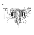
図1は、本発明の一実施形態に係るモータの断面図、図2は、図1のステーターの分解斜視図、そして、図3は、図2の要部拡大図である。 1 is a cross-sectional view of a motor according to an embodiment of the present invention, FIG. 2 is an exploded perspective view of the stator of FIG. 1, and FIG. 3 is an enlarged view of a main part of FIG.
本発明に係るモータは、図1に示したように、モータハウジング1、ステーター2、ローター3、及び回転軸4を含む。 As shown in FIG. 1, the motor according to the present invention includes a motor housing 1, a stator 2, a rotor 3, and a rotating shaft 4.
モータハウジング1は、上側が開口した状態で設けられ、内部にステーター2が固定配置されてもよい。モータハウジング1の形状は、使用されるモータの種類によって種々に形成され、デュアルクラッチトランスミッション(DCT、Dual−clutch Transmission)等のモータに用いられる場合、図1に示した形態のモータハウジング1が一対で設けられてもよい。この時、オープンされたモータハウジング1の上側面には、後述するローターの回転軸4と連結及び連結解除される動力出力軸が配置され、ローター3から出力される動力が選択的に伝達される。 The motor housing 1 may be provided with the upper side opened, and the stator 2 may be fixedly disposed therein. The shape of the motor housing 1 is variously formed according to the type of motor used. When the motor housing 1 is used for a motor such as a dual clutch transmission (DCT), a pair of the motor housings 1 shown in FIG. May be provided. At this time, on the upper side surface of the opened motor housing 1, a power output shaft connected to and disconnected from the rotor rotating shaft 4 described later is disposed, and the power output from the rotor 3 is selectively transmitted. .
デュアルクラッチトランスミッションは、従来の手動トランスミッションの車両に搭載される単板のクラッチトランスミッションとは異なって、2組のクラッチを搭載しており、一つのクラッチを介して伝達される動力で1、3、5段を実現し、残りの一つのクラッチを介して伝達される動力で2、4、6段を実現できるようにするシステムである。デュアルクラッチトランスミッションは、従来の自動トランスミッションの車両のような便利な運転性及びスムーズな変速感を提供すると共に、従来の手動トランスミッションの車両より高燃費を発揮できる特徴がある。 Unlike a single-plate clutch transmission mounted on a conventional manual transmission vehicle, the dual clutch transmission is equipped with two sets of clutches, and the power transmitted through one clutch is 1, 3, This is a system that realizes five stages and realizes two, four, and six stages with power transmitted through the remaining one clutch. The dual clutch transmission has features such as convenient driving performance and smooth shifting feeling as in a conventional automatic transmission vehicle, and higher fuel efficiency than a conventional manual transmission vehicle.
一般に、デュアルクラッチトランスミッションは、2組のクラッチからなるデュアルクラッチと、デュアルクラッチから動力が伝達されて各変速段を設定するトランスミッション制御ユニットと、デュアルクラッチのクラッチを各々制御するクラッチアクチュエータと、トランスミッション制御ユニットにセレクティング(selecting)及びシフティング(shifting)操作を加えて変速を行う変速アクチュエータと、車速など車両の各種情報と変速命令が伝達されてクラッチアクチュエータ及び変速アクチュエータを電子的に制御する電子制御ユニットとからなる。 In general, a dual clutch transmission includes a dual clutch composed of two sets of clutches, a transmission control unit that transmits power from the dual clutch to set each gear stage, a clutch actuator that controls each clutch of the dual clutch, and a transmission control. An electronic control that electronically controls the clutch actuator and the shift actuator by transmitting a variety of vehicle information such as vehicle speed and a shift command by performing a shifting operation by selecting and shifting the unit. It consists of units.
従って、クラッチアクチュエータのセレクティング動作によってモータハウジング1に設置されているステーター2とローター3の出力軸とが連結されて、各々のトランスミッションに動力を伝達することができる。 Therefore, the stator 2 installed in the motor housing 1 and the output shaft of the rotor 3 are connected by the selecting operation of the clutch actuator, and power can be transmitted to each transmission.
ステーター2は、モータハウジング1の内側に設けられるものであり、好ましくは、図示したように、モータハウジング1の内部空間部を形成する円筒状のステーター安着部に結合されてもよい。ステーター2は、磁束形成のための金属材質のステーターコア30に複数の歯を形成し、歯にコイルを巻線し、コイルに電源を印加して磁場を形成することができる。この時、歯を有するステーターコアにはインシュレーターを設置した状態でその上にコイルを巻線して、ステーターコアには電気が流れないように構成することができる。一方、歯の数は、モータの大きさと出力に応じて増減できる。
The stator 2 is provided inside the motor housing 1, and may be preferably coupled to a cylindrical stator seating portion that forms an internal space portion of the motor housing 1 as illustrated. The stator 2 can form a magnetic field by forming a plurality of teeth on a
ローター3は、回転軸4が中央に結合されるコア部材3aと、コア部材3aに圧入結合される磁石部材3bとで構成されてもよい。
The rotor 3 may be composed of a
一方、ステーター2には、図2及び図3に示したように、略リング状に設けられたインシュレーター本体10が、ステーターコア30の上側に設置されてもよい。インシュレーター本体10は、一側端部に突出するようにターミナルハウジング結合部20が一体に形成される。一般に、インシュレーター本体10は、樹脂材質で射出成形されるため、ターミナルハウジング結合部20は、インシュレーター本体10と同じ材質で金型から射出成形されることが好ましい。ターミナルハウジング結合部20には、図示しない電源部との連結のため、図示しないターミナルハウジングが着脱可能に結合されてもよい。
On the other hand, as shown in FIGS. 2 and 3, the
インシュレーター本体10の中央には、図2に示したように、複数の歯が形成され、インシュレーター本体10と結合されるステーターコア30の中央に形成された歯(図示せず)と1:1対応して結合できる。歯ガイドは、歯に巻線されるコイルが通電性材質で形成されるステーターコア30とショートされることを防止する役割を果たすことができる。
As shown in FIG. 2, a plurality of teeth are formed at the center of the
一般に、インシュレーター本体10は樹脂材質で射出成形されるため、ターミナルハウジング結合部20は、インシュレーター本体10と同じ材質で金型から射出成形されることが好ましい。ターミナルハウジング結合部20には、図示しない電源部との連結のためのターミナルハウジング100が固定ユニット130によって着脱可能に結合される。
In general, since the
固定ユニット130は、ターミナルハウジング100に設けられたサイドガイドプレート110と、ターミナルハウジング結合部20に設けられた係止部材120とで構成される。
The fixed
サイドガイドプレート110は、図2及び図3に示したように、略六面体に形成されたターミナルハウジング100の両先端に図面の上側方向に突設されるものであって、係止部材120と対応する位置には、弧状の係止部111、及びターミナルハウジング100の回転角度を規制するための規制溝112を含んでもよい。
As shown in FIGS. 2 and 3, the
サイドガイドプレート110は、ターミナルハウジング100をインシュレーター本体10と一体に形成されたターミナルハウジング結合部20側に固定するが、インシュレーター本体10を含むステート2をハウジング1に組み立てながらターミナルハウジング100の下側で電源ターミナル150が結合する際、一定の角度で回転可能に設けられ、組立過程において電源ターミナル150とターミナルハウジング100の組立性を向上させることができる。
The
係止部111は、係止部材120がスナップフィット結合できるように、係止部材120と対応する形状に設けられてもよい。係止部111は、係止部材120よりは大きく形成されて、係止部材120が係止部111の内部で回転可能に組み立てられる。
The locking part 111 may be provided in a shape corresponding to the locking
規制溝112は、係止部材120に形成される規制突起123と対応する位置に形成され、規制溝112の方向及び大きさは設計によって多様に構成される。例えば、規制溝112の角度(α)は、図2及び図3で示したように、係止部111の中心で電源ターミナル150の挿入方向と垂直な仮想の線(a)を基準に15乃至25度になるように規制溝112を形成してもよい。本発明の一実施形態によると、規制溝112の形成角度は20度になるように形成されるが、これに限定されず、設計必要に応じて適宜可変される。このように規制溝112を形成すると、係止部材120を中心にターミナルハウジング100が回転する角度が係止部材120とサイドガイドプレート110のギャップにより一部流動するだけで、ターミナルハウジング100が回転することは規制できるため、ターミナルハウジング100がハウジング1に挿入される組立工程中に、電源ターミナル150と結合する過程でハウジング1と干渉が生じて破損したり、過度に固堅に固定されて組立過程で破損したりするなどの不良を防止することができる。
The
係止部材120は、ターミナルハウジング結合部20のサイドガイドプレート110に向き合う方向に突設されるもので、係止突起121、進入部122及び規制突起123を含んでもよい。
The locking
係止突起121は、進入部122の後端に設けられてもよい。係止突起121は、ターミナルハウジング100の結合位置において、係止部111にフックされ、ターミナルハウジング結合部20からターミナルハウジング100が離脱することを防止する。係止突起121は、サイドガイドプレート110に形成された係止部111にフック結合されるが、これら各々の接触面は弧状に設けられるため、丸く形成された係止部111の内周面と係止突起121の外周面は互いにスライディング回転可能である。
The locking
進入部122は、ターミナルハウジング100の挿入方向(図2の矢印A方向)に対して所定角度を有するスライディング傾斜面を有するように設けられる。従って、サイドガイドプレート110が、係止部材120の対応する位置に挿入される場合、サイドガイドプレート110を挿入方向に垂直な方向(矢印B方向)に弾性変形させることができる。
The
規制突起123は、係止部材120の一側に突設されるが、本発明の好ましい一実施形態によると、図2及び図3に示したように、一定の長さを有する直線状の突起で設けられてもよい。この時、規制突起123は、係止部材120の中心を基準に一定の角度を有するように設けられるが、本発明の一実施形態によると、係止部材120の中心を基準に20度の角度を有することができる。この規制突起123によって係止突起121と係止部111が制限なしに回転移動することが防止される。
The restricting
センターガイドプレート125は、図2に示したように、係止部材120の間に介在されて、ターミナルハウジング100の挿入時、挿入方向をガイドし、ターミナルハウジング100が結合位置に固定された場合、ターミナルハウジング100の回転を抑制する。このように、センターガイドプレート125をインシュレーター本体10とターミナルハウジング100との間に介在すると、インシュレーター本体10にコイルを巻線する途中でターミナルハウジング100が回転しながら離脱することを防止することができ、ターミナルハウジング100の結合を堅固に維持することができる。また、センターガイドプレート125が、ターミナルハウジング100の挿入方向と平行方向に延設されるため、ターミナルハウジング100の挿入時、ターミナルハウジング100が捩れることなく、結合位置に挿入可能である。
As shown in FIG. 2, the center guide plate 125 is interposed between the locking
上記で説明し、図面に図示された本発明の実施形態は、本発明の技術的思想を限定するものと解釈されてはいけない。本発明の保護範囲は、特許請求の範囲に記載された事項によってのみ制限され、本発明の技術分野において通常の知識を有する者は、本発明の技術的思想を多様な形態で改良変更することができる。従って、このような改良及び変更は、通常の知識を有する者に自明である限り、本発明の保護範囲に属するものである。 The embodiments of the present invention described above and illustrated in the drawings should not be construed as limiting the technical idea of the present invention. The scope of protection of the present invention is limited only by the matters described in the claims, and those having ordinary knowledge in the technical field of the present invention can improve and change the technical idea of the present invention in various forms. Can do. Accordingly, such improvements and modifications are within the protection scope of the present invention as long as they are obvious to those having ordinary knowledge.
1 モータハウジング
2 ステーター
3 ローター
4 ローターの回転軸
10 インシュレーター本体
20 ターミナルハウジング結合部
30 ステーターコア
100 ターミナルハウジング
110 サイドガイドプレート
111 係止部
112 規制溝
120 係止部材
121 係止突起
122 進入部
123 規制突起
125 センターガイドプレート
130 固定ユニット
150 電源ターミナル
DESCRIPTION OF SYMBOLS 1 Motor housing 2 Stator 3 Rotor 4 Rotor's
Claims (10)
前記インシュレーター本体と一体に構成され、インシュレーター本体の円周方向に突出されたターミナルハウジング結合部と、
モータに電源を供給できるように、前記ターミナルハウジング結合部に脱着できるように結合されるターミナルハウジングと、
前記ターミナルハウジング結合部に前記ターミナルハウジングを位置固定する固定ユニットと、
前記ターミナルハウジング結合部に対する前記ターミナルハウジングの回転角度を規制する規制ユニットと、を含み、
前記固定ユニットは、前記ターミナルハウジングに具備されたサイドガイドプレートと、
前記ターミナルハウジング結合部に具備された係止部材と、を含み、
前記規制ユニットは、前記係止部材に対応する位置に形成された係止部を含むことを特徴とする、モータ。 An insulator body coupled to a stator core around which a plurality of coils to which power supplies of different polarities are applied are wound;
Said configured insulator body integrally, are projected in the circumferential direction of the insulator body has terminal housing coupling unit,
A terminal housing coupled so as to be detachable from the terminal housing coupling part so that power can be supplied to the motor;
A fixing unit for fixing the position of the terminal housing to the terminal housing coupling portion;
See containing and a regulatory unit you restrict rotation angle of the terminal housing for said terminal housing coupling unit,
The fixing unit includes a side guide plate provided in the terminal housing,
A locking member provided in the terminal housing coupling portion,
The motor according to claim 1, wherein the restriction unit includes a locking portion formed at a position corresponding to the locking member .
前記ターミナルハウジングの両先端に突設される、請求項1に記載のモータ。 The side guide plate is
The motor according to claim 1 , wherein the motor protrudes from both ends of the terminal housing.
一部の区間に弧状の内周面を有する通孔と、
前記係止部の通孔から所定角度に延長される規制溝と、
を含む、請求項1または2に記載のモータ。 The locking portion is
A through hole having an inner peripheral surface of the arcuate part of the section,
A restriction groove extending at a predetermined angle from the through hole of the locking portion;
Including, motor according to claim 1 or 2.
前記係止部材と対応する形状に形成され、前記係止部材にスナップフィット結合される、請求項1乃至3のいずれか一項に記載のモータ。 The locking portion is
The motor according to any one of claims 1 to 3, wherein the motor is formed in a shape corresponding to the locking member and is snap-fit coupled to the locking member.
前記ターミナルハウジング結合部の前記サイドガイドプレートに対向するように突出する、請求項1乃至5のいずれか一項に記載のモータ。 The locking member is
The motor according to claim 1 , wherein the motor projects so as to face the side guide plate of the terminal housing coupling portion.
係止突起と、
前記係止突起の一側端部上に形成された進入部と、
前記係止突起の一側方向に延長されて前記規制溝に結合される規制突起と、
を含む、請求項3乃至6のいずれか一項に記載のモータ。 The locking member is
A locking projection;
An entry portion formed on one end of the locking projection;
A restriction protrusion extended in one side direction of the locking protrusion and coupled to the restriction groove ;
The motor according to claim 3 , comprising:
前記係止部と接触する面が弧状である、請求項7に記載のモータ。 The locking projection is
The motor according to claim 7 , wherein a surface in contact with the locking portion is arcuate.
Applications Claiming Priority (2)
| Application Number | Priority Date | Filing Date | Title |
|---|---|---|---|
| KR1020120082105A KR101353798B1 (en) | 2012-07-27 | 2012-07-27 | Motor |
| KR10-2012-0082105 | 2012-07-27 |
Publications (3)
| Publication Number | Publication Date |
|---|---|
| JP2014027873A JP2014027873A (en) | 2014-02-06 |
| JP2014027873A5 JP2014027873A5 (en) | 2016-08-25 |
| JP6158625B2 true JP6158625B2 (en) | 2017-07-05 |
Family
ID=48900773
Family Applications (1)
| Application Number | Title | Priority Date | Filing Date |
|---|---|---|---|
| JP2013155450A Active JP6158625B2 (en) | 2012-07-27 | 2013-07-26 | motor |
Country Status (5)
| Country | Link |
|---|---|
| US (1) | US9490677B2 (en) |
| EP (1) | EP2690758B1 (en) |
| JP (1) | JP6158625B2 (en) |
| KR (1) | KR101353798B1 (en) |
| CN (1) | CN103580343B (en) |
Families Citing this family (4)
| Publication number | Priority date | Publication date | Assignee | Title |
|---|---|---|---|---|
| JP6702212B2 (en) * | 2017-01-31 | 2020-05-27 | 株式会社デンソー | Drive |
| JP7033475B2 (en) * | 2018-03-27 | 2022-03-10 | 株式会社山田製作所 | Motor stator |
| DE102020130615A1 (en) * | 2020-11-19 | 2022-05-19 | Schaeffler Technologies AG & Co. KG | Mechanical connection unit, stator and electrical machine |
| JP2024051191A (en) * | 2022-09-30 | 2024-04-11 | 本田技研工業株式会社 | Rotary electric machine |
Family Cites Families (15)
| Publication number | Priority date | Publication date | Assignee | Title |
|---|---|---|---|---|
| JPH03230738A (en) | 1990-02-06 | 1991-10-14 | Mitsubishi Electric Corp | Motor |
| US5717273A (en) | 1996-02-28 | 1998-02-10 | Onan Corporation | Insulating armature end turn cap |
| JP2000354347A (en) * | 1999-06-08 | 2000-12-19 | Sanyo Denki Co Ltd | Stator for rotating electric machine |
| JP2001169497A (en) * | 1999-12-06 | 2001-06-22 | Moriyama Manufacturing Co Ltd | Stator for ac generator |
| JP2004071503A (en) | 2002-08-09 | 2004-03-04 | Asmo Co Ltd | Connector and motor device equipped with the connector |
| KR100543096B1 (en) * | 2003-11-28 | 2006-01-20 | 삼성광주전자 주식회사 | Motor |
| JP4594026B2 (en) * | 2004-10-07 | 2010-12-08 | 多摩川精機株式会社 | Resolver external conductor fixing structure |
| JP2008125309A (en) | 2006-11-15 | 2008-05-29 | Mitsuba Corp | Brushless motor |
| JP2008187787A (en) | 2007-01-29 | 2008-08-14 | Nippon Densan Corp | Resolver and motor |
| WO2008105054A1 (en) | 2007-02-26 | 2008-09-04 | Mitsubishi Electric Corporation | Stator of motor and motor and pump and method for manufacturing motor |
| KR101396428B1 (en) * | 2008-01-25 | 2014-05-19 | 삼성디스플레이 주식회사 | Lamp socket, liquid crystal display and method of manufacturing liquid crystal display |
| JP4972593B2 (en) | 2008-03-24 | 2012-07-11 | 株式会社ミツバ | Electric motor and method for manufacturing electric motor |
| JP5692593B2 (en) * | 2011-05-11 | 2015-04-01 | 株式会社デンソー | Drive device |
| CN102290900A (en) | 2011-08-22 | 2011-12-21 | 广东威灵电机制造有限公司 | Plastic package motor |
| KR101848922B1 (en) * | 2011-09-21 | 2018-04-13 | 엘지이노텍 주식회사 | Terminal connection structure for Motor |
-
2012
- 2012-07-27 KR KR1020120082105A patent/KR101353798B1/en active IP Right Grant
-
2013
- 2013-07-24 EP EP13177913.4A patent/EP2690758B1/en active Active
- 2013-07-25 US US13/951,013 patent/US9490677B2/en active Active
- 2013-07-26 JP JP2013155450A patent/JP6158625B2/en active Active
- 2013-07-29 CN CN201310322461.6A patent/CN103580343B/en active Active
Also Published As
| Publication number | Publication date |
|---|---|
| KR101353798B1 (en) | 2014-01-23 |
| US20140028129A1 (en) | 2014-01-30 |
| EP2690758B1 (en) | 2021-07-14 |
| CN103580343B (en) | 2016-03-23 |
| US9490677B2 (en) | 2016-11-08 |
| JP2014027873A (en) | 2014-02-06 |
| CN103580343A (en) | 2014-02-12 |
| EP2690758A2 (en) | 2014-01-29 |
| EP2690758A3 (en) | 2018-02-14 |
Similar Documents
| Publication | Publication Date | Title |
|---|---|---|
| US10574098B2 (en) | Stator, motor comprising the same and method for making the same | |
| CN101378214B (en) | Electric motor | |
| JP5743409B2 (en) | Electric motor | |
| KR101558349B1 (en) | Rotor structure of drive motor | |
| US20060082242A1 (en) | Stator arrangement for an electric machine and an electric motor | |
| WO2012090295A1 (en) | Stator and rotating electric machine equipped with this stator | |
| JP2008131683A (en) | Axial air gap type motor | |
| JP5920637B2 (en) | Rotating electrical machine rotor | |
| JP6158625B2 (en) | motor | |
| KR101911723B1 (en) | Motor | |
| JP5714871B2 (en) | Electric motor and drive device | |
| JP2015208223A (en) | Motor for electric power steering device | |
| WO2020156139A1 (en) | Electric motor, stator assembly, and winding support therefor | |
| KR20180047480A (en) | Slotless BLCD Motor | |
| KR20170060501A (en) | Rotor for Wound Rotor Synchronous Motor | |
| WO2019102736A1 (en) | Rotating electric machine and stator | |
| JP2009124921A (en) | Electric motor | |
| JP6595346B2 (en) | motor | |
| CN103855819A (en) | Electric actuator | |
| KR102570833B1 (en) | Stator assembly and motor including the same | |
| JP2012039681A (en) | Armature core of vehicle rotary electric machine | |
| KR102143030B1 (en) | Hybrid stator, motor using the same, and manufacturing method thereof | |
| JP6316016B2 (en) | Motor with reduction gear | |
| CN115882635A (en) | Rotor subassembly, motor and electrical equipment | |
| KR101307029B1 (en) | Permanent magnet motor |
Legal Events
| Date | Code | Title | Description |
|---|---|---|---|
| A521 | Request for written amendment filed |
Free format text: JAPANESE INTERMEDIATE CODE: A523 Effective date: 20160707 |
|
| A621 | Written request for application examination |
Free format text: JAPANESE INTERMEDIATE CODE: A621 Effective date: 20160707 |
|
| A977 | Report on retrieval |
Free format text: JAPANESE INTERMEDIATE CODE: A971007 Effective date: 20170420 |
|
| TRDD | Decision of grant or rejection written | ||
| A01 | Written decision to grant a patent or to grant a registration (utility model) |
Free format text: JAPANESE INTERMEDIATE CODE: A01 Effective date: 20170509 |
|
| A61 | First payment of annual fees (during grant procedure) |
Free format text: JAPANESE INTERMEDIATE CODE: A61 Effective date: 20170608 |
|
| R150 | Certificate of patent or registration of utility model |
Ref document number: 6158625 Country of ref document: JP Free format text: JAPANESE INTERMEDIATE CODE: R150 |
|
| R250 | Receipt of annual fees |
Free format text: JAPANESE INTERMEDIATE CODE: R250 |
|
| R250 | Receipt of annual fees |
Free format text: JAPANESE INTERMEDIATE CODE: R250 |
|
| R250 | Receipt of annual fees |
Free format text: JAPANESE INTERMEDIATE CODE: R250 |
|
| R250 | Receipt of annual fees |
Free format text: JAPANESE INTERMEDIATE CODE: R250 |
|
| R250 | Receipt of annual fees |
Free format text: JAPANESE INTERMEDIATE CODE: R250 |