JP6156458B2 - Motor control device, electric power steering device, and vehicle - Google Patents
Motor control device, electric power steering device, and vehicle Download PDFInfo
- Publication number
- JP6156458B2 JP6156458B2 JP2015159584A JP2015159584A JP6156458B2 JP 6156458 B2 JP6156458 B2 JP 6156458B2 JP 2015159584 A JP2015159584 A JP 2015159584A JP 2015159584 A JP2015159584 A JP 2015159584A JP 6156458 B2 JP6156458 B2 JP 6156458B2
- Authority
- JP
- Japan
- Prior art keywords
- motor
- electrical angle
- motor electrical
- unit
- initial value
- Prior art date
- Legal status (The legal status is an assumption and is not a legal conclusion. Google has not performed a legal analysis and makes no representation as to the accuracy of the status listed.)
- Active
Links
Images


Classifications
-
- B—PERFORMING OPERATIONS; TRANSPORTING
- B62—LAND VEHICLES FOR TRAVELLING OTHERWISE THAN ON RAILS
- B62D—MOTOR VEHICLES; TRAILERS
- B62D5/00—Power-assisted or power-driven steering
- B62D5/04—Power-assisted or power-driven steering electrical, e.g. using an electric servo-motor connected to, or forming part of, the steering gear
- B62D5/0457—Power-assisted or power-driven steering electrical, e.g. using an electric servo-motor connected to, or forming part of, the steering gear characterised by control features of the drive means as such
- B62D5/0481—Power-assisted or power-driven steering electrical, e.g. using an electric servo-motor connected to, or forming part of, the steering gear characterised by control features of the drive means as such monitoring the steering system, e.g. failures
- B62D5/0487—Power-assisted or power-driven steering electrical, e.g. using an electric servo-motor connected to, or forming part of, the steering gear characterised by control features of the drive means as such monitoring the steering system, e.g. failures detecting motor faults
-
- H—ELECTRICITY
- H02—GENERATION; CONVERSION OR DISTRIBUTION OF ELECTRIC POWER
- H02P—CONTROL OR REGULATION OF ELECTRIC MOTORS, ELECTRIC GENERATORS OR DYNAMO-ELECTRIC CONVERTERS; CONTROLLING TRANSFORMERS, REACTORS OR CHOKE COILS
- H02P6/00—Arrangements for controlling synchronous motors or other dynamo-electric motors using electronic commutation dependent on the rotor position; Electronic commutators therefor
- H02P6/14—Electronic commutators
- H02P6/16—Circuit arrangements for detecting position
-
- B—PERFORMING OPERATIONS; TRANSPORTING
- B62—LAND VEHICLES FOR TRAVELLING OTHERWISE THAN ON RAILS
- B62D—MOTOR VEHICLES; TRAILERS
- B62D15/00—Steering not otherwise provided for
- B62D15/02—Steering position indicators ; Steering position determination; Steering aids
- B62D15/021—Determination of steering angle
-
- B—PERFORMING OPERATIONS; TRANSPORTING
- B62—LAND VEHICLES FOR TRAVELLING OTHERWISE THAN ON RAILS
- B62D—MOTOR VEHICLES; TRAILERS
- B62D5/00—Power-assisted or power-driven steering
- B62D5/04—Power-assisted or power-driven steering electrical, e.g. using an electric servo-motor connected to, or forming part of, the steering gear
- B62D5/0457—Power-assisted or power-driven steering electrical, e.g. using an electric servo-motor connected to, or forming part of, the steering gear characterised by control features of the drive means as such
- B62D5/046—Controlling the motor
- B62D5/0463—Controlling the motor calculating assisting torque from the motor based on driver input
-
- B—PERFORMING OPERATIONS; TRANSPORTING
- B62—LAND VEHICLES FOR TRAVELLING OTHERWISE THAN ON RAILS
- B62D—MOTOR VEHICLES; TRAILERS
- B62D5/00—Power-assisted or power-driven steering
- B62D5/04—Power-assisted or power-driven steering electrical, e.g. using an electric servo-motor connected to, or forming part of, the steering gear
- B62D5/0457—Power-assisted or power-driven steering electrical, e.g. using an electric servo-motor connected to, or forming part of, the steering gear characterised by control features of the drive means as such
- B62D5/0481—Power-assisted or power-driven steering electrical, e.g. using an electric servo-motor connected to, or forming part of, the steering gear characterised by control features of the drive means as such monitoring the steering system, e.g. failures
- B62D5/0484—Power-assisted or power-driven steering electrical, e.g. using an electric servo-motor connected to, or forming part of, the steering gear characterised by control features of the drive means as such monitoring the steering system, e.g. failures for reaction to failures, e.g. limp home
-
- B—PERFORMING OPERATIONS; TRANSPORTING
- B62—LAND VEHICLES FOR TRAVELLING OTHERWISE THAN ON RAILS
- B62D—MOTOR VEHICLES; TRAILERS
- B62D5/00—Power-assisted or power-driven steering
- B62D5/04—Power-assisted or power-driven steering electrical, e.g. using an electric servo-motor connected to, or forming part of, the steering gear
- B62D5/0457—Power-assisted or power-driven steering electrical, e.g. using an electric servo-motor connected to, or forming part of, the steering gear characterised by control features of the drive means as such
- B62D5/0481—Power-assisted or power-driven steering electrical, e.g. using an electric servo-motor connected to, or forming part of, the steering gear characterised by control features of the drive means as such monitoring the steering system, e.g. failures
- B62D5/049—Power-assisted or power-driven steering electrical, e.g. using an electric servo-motor connected to, or forming part of, the steering gear characterised by control features of the drive means as such monitoring the steering system, e.g. failures detecting sensor failures
-
- B—PERFORMING OPERATIONS; TRANSPORTING
- B62—LAND VEHICLES FOR TRAVELLING OTHERWISE THAN ON RAILS
- B62D—MOTOR VEHICLES; TRAILERS
- B62D5/00—Power-assisted or power-driven steering
- B62D5/04—Power-assisted or power-driven steering electrical, e.g. using an electric servo-motor connected to, or forming part of, the steering gear
- B62D5/0457—Power-assisted or power-driven steering electrical, e.g. using an electric servo-motor connected to, or forming part of, the steering gear characterised by control features of the drive means as such
- B62D5/0481—Power-assisted or power-driven steering electrical, e.g. using an electric servo-motor connected to, or forming part of, the steering gear characterised by control features of the drive means as such monitoring the steering system, e.g. failures
- B62D5/0493—Power-assisted or power-driven steering electrical, e.g. using an electric servo-motor connected to, or forming part of, the steering gear characterised by control features of the drive means as such monitoring the steering system, e.g. failures detecting processor errors, e.g. plausibility of steering direction
-
- H—ELECTRICITY
- H02—GENERATION; CONVERSION OR DISTRIBUTION OF ELECTRIC POWER
- H02P—CONTROL OR REGULATION OF ELECTRIC MOTORS, ELECTRIC GENERATORS OR DYNAMO-ELECTRIC CONVERTERS; CONTROLLING TRANSFORMERS, REACTORS OR CHOKE COILS
- H02P25/00—Arrangements or methods for the control of AC motors characterised by the kind of AC motor or by structural details
- H02P25/16—Arrangements or methods for the control of AC motors characterised by the kind of AC motor or by structural details characterised by the circuit arrangement or by the kind of wiring
- H02P25/22—Multiple windings; Windings for more than three phases
-
- H—ELECTRICITY
- H02—GENERATION; CONVERSION OR DISTRIBUTION OF ELECTRIC POWER
- H02P—CONTROL OR REGULATION OF ELECTRIC MOTORS, ELECTRIC GENERATORS OR DYNAMO-ELECTRIC CONVERTERS; CONTROLLING TRANSFORMERS, REACTORS OR CHOKE COILS
- H02P29/00—Arrangements for regulating or controlling electric motors, appropriate for both AC and DC motors
- H02P29/02—Providing protection against overload without automatic interruption of supply
- H02P29/024—Detecting a fault condition, e.g. short circuit, locked rotor, open circuit or loss of load
- H02P29/028—Detecting a fault condition, e.g. short circuit, locked rotor, open circuit or loss of load the motor continuing operation despite the fault condition, e.g. eliminating, compensating for or remedying the fault
-
- H—ELECTRICITY
- H02—GENERATION; CONVERSION OR DISTRIBUTION OF ELECTRIC POWER
- H02P—CONTROL OR REGULATION OF ELECTRIC MOTORS, ELECTRIC GENERATORS OR DYNAMO-ELECTRIC CONVERTERS; CONTROLLING TRANSFORMERS, REACTORS OR CHOKE COILS
- H02P29/00—Arrangements for regulating or controlling electric motors, appropriate for both AC and DC motors
- H02P29/02—Providing protection against overload without automatic interruption of supply
- H02P29/032—Preventing damage to the motor, e.g. setting individual current limits for different drive conditions
Landscapes
- Engineering & Computer Science (AREA)
- Chemical & Material Sciences (AREA)
- Combustion & Propulsion (AREA)
- Transportation (AREA)
- Mechanical Engineering (AREA)
- Power Engineering (AREA)
- Control Of Ac Motors In General (AREA)
- Power Steering Mechanism (AREA)
- Steering Control In Accordance With Driving Conditions (AREA)
- Control Of Electric Motors In General (AREA)
- Control Of Motors That Do Not Use Commutators (AREA)
Description
本発明は、電動パワーステアリング装置に搭載された多相電動モータを駆動制御するモータ制御装置に関する。 The present invention relates to a motor control device that drives and controls a multiphase electric motor mounted on an electric power steering device.
車両に搭載する電動パワーステアリング装置の電動モータを制御するモータ制御装置として、例えば、特許文献1に記載の多相回転機の制御装置が開示されている。
特許文献1に記載された従来例にあっては、レゾルバ等の位置センサによってロータ回転位置θを検出し、指令電圧Vd1、Vq1及びロータ回転位置θに基づき、三相電圧指令値であるU相指令電圧Vuu*1、V相指令電圧Vvu*1、及び、W相指令電圧Vwu*1を算出する。
As a motor control device that controls an electric motor of an electric power steering device mounted on a vehicle, for example, a control device for a multiphase rotating machine described in Patent Document 1 is disclosed.
In the conventional example described in Patent Document 1, the rotor rotational position θ is detected by a position sensor such as a resolver, and the U-phase which is a three-phase voltage command value based on the command voltages Vd1, Vq1 and the rotor rotational position θ. The command voltage Vuu * 1, the V-phase command voltage Vvu * 1, and the W-phase command voltage Vwu * 1 are calculated.
しかしながら、上記特許文献1の従来例では、ロータ回転位置を検出する位置センサが故障した場合を考慮していないため、故障後は多相回転機を的確に駆動制御することが困難となる。
そこで、本発明は、上記従来例の未解決の課題に着目してなされたものであり、モータ電気角を検出するモータ電気角検出部に故障が生じた場合でも電動モータを的確に駆動制御することが可能なモータ制御装置、電動パワーステアリング装置及び車両を提供することを目的としている。
However, since the conventional example of Patent Document 1 does not consider the case where the position sensor that detects the rotor rotational position fails, it is difficult to accurately drive and control the multiphase rotating machine after the failure.
Therefore, the present invention has been made paying attention to the unsolved problems of the above-described conventional example, and accurately controls the drive of the electric motor even when a failure occurs in the motor electrical angle detection unit that detects the motor electrical angle. It is an object of the present invention to provide a motor control device, an electric power steering device, and a vehicle that can be used.
上記目的を解決するために、本発明の第1の態様に係るモータ制御装置は、システム再起動後の初期診断において、操舵補助力を発生する多相電動モータのモータ電気角を検出するモータ電気角検出部が異常と診断されると、前記多相電動モータへのモータ駆動信号の入力に応じた前記多相電動モータの応答出力に基づき前記モータ電気角の初期値を推定するモータ電気角初期値推定部と、ステアリングの舵角を検出するステアリング舵角検出部で検出した舵角と前記モータ電気角初期値推定部で推定した前記初期値とに基づき前記モータ電気角を推定するモータ電気角推定部と、前記モータ電気角検出部が正常時は前記モータ電気角検出部で検出したモータ電気角に基づき前記多相電動モータを駆動制御し、前記システム再起動後の初期診断で前記モータ電気角検出部が異常と診断時は前記モータ電気角推定部で推定したモータ電気角推定値に基づき前記多相電動モータを駆動制御するモータ駆動制御部と、を備える。 In order to solve the above-described object, the motor control device according to the first aspect of the present invention is a motor control device that detects a motor electrical angle of a multiphase electric motor that generates a steering assist force in an initial diagnosis after system restart. When the angle detection unit is diagnosed as abnormal, the initial value of the motor electrical angle is estimated based on the response output of the multiphase electric motor according to the input of the motor drive signal to the multiphase electric motor. A motor electrical angle for estimating the motor electrical angle based on a steering angle detected by a value estimation unit, a steering angle detection unit for detecting a steering angle of the steering, and the initial value estimated by the motor electrical angle initial value estimation unit When the estimation unit and the motor electrical angle detection unit are normal, the multiphase electric motor is driven and controlled based on the motor electrical angle detected by the motor electrical angle detection unit, and the initial diagnosis after the system is restarted In the time of diagnosis and the motor electrical angle detection unit is abnormal and a motor drive control unit for driving and controlling the multi-phase electric motor based on the motor electrical angle estimate value estimated by the motor electrical angle estimate unit.
また、本発明の第2の態様に係る電動パワーステアリング装置は、上記第1の態様に係るモータ制御装置を備える。
さらに、本発明の第3の態様に係る車両は、上記第2の態様に係る電動パワーステアリング装置を備える。
An electric power steering apparatus according to the second aspect of the present invention includes the motor control apparatus according to the first aspect.
Furthermore, a vehicle according to a third aspect of the present invention includes the electric power steering device according to the second aspect.
本発明によれば、システム再起動後の初期診断においてモータ電気角検出部が異常と診断されると、多相電動モータへのモータ駆動信号の入力に応じた多相電動モータの応答出力に基づきモータ電気角の初期値を推定することが可能である。そして、この推定したモータ電気角の初期値とステアリングの舵角とに基づきモータ電気角を推定し、このモータ電気角推定値に基づき多相電動モータを駆動制御することが可能である。これにより、システム停止前又は停止中にモータ電気角検出部に異常が発生した場合でも多相電動モータを正常時と遜色なく駆動制御することが可能となる。 According to the present invention, when the motor electrical angle detector is diagnosed as abnormal in the initial diagnosis after the system is restarted, based on the response output of the multiphase electric motor according to the input of the motor drive signal to the multiphase electric motor. It is possible to estimate the initial value of the motor electrical angle. Then, it is possible to estimate the motor electrical angle based on the estimated initial value of the motor electrical angle and the steering angle of the steering, and to drive and control the multiphase electric motor based on the estimated motor electrical angle. As a result, even when an abnormality occurs in the motor electrical angle detection unit before or during the system stop, the multi-phase electric motor can be driven and controlled as if it is normal.
また、上記効果を有するモータ制御装置を含んで電動パワーステアリング装置を構成するので、システム停止前又は停止中にモータ電気角検出部に異常が発生した場合でも多相電動モータをモータ電気角推定値により駆動制御することができ電動パワーステアリング装置の操舵補助機能の継続が可能となる。
さらに、上記効果を有する電動パワーステアリング装置を含んで車両を構成するので、モータ電気角検出部に異常が発生した場合でも電動パワーステアリング装置の操舵補助機能の継続が可能となるので、信頼性を向上させることが可能となる。
In addition, since the electric power steering apparatus is configured including the motor control apparatus having the above-described effects, even if an abnormality occurs in the motor electric angle detection unit before or during the system stop, the multiphase electric motor is estimated as the motor electric angle estimated value. Therefore, it is possible to control the driving of the electric power steering apparatus and to continue the steering assist function.
Furthermore, since the vehicle is configured to include the electric power steering device having the above-described effects, the steering assist function of the electric power steering device can be continued even when an abnormality occurs in the motor electrical angle detection unit. It becomes possible to improve.
次に、図面に基づき、本発明の第1〜第3実施形態を説明する。以下の図面の記載において、同一又は類似の部分には同一又は類似の符号を付している。ただし、図面は模式的なものであり、寸法の関係や比率等は現実のものとは異なる場合があることに留意すべきである。
また、以下に示す第1〜第3実施形態は、本発明の技術的思想を具体化するための装置や方法を例示するものであって、本発明の技術的思想は、構成部品の材質、形状、構造、配置等を下記のものに特定するものでない。本発明の技術的思想は、特許請求の範囲に記載された請求項が規定する技術的範囲内において、種々の変更を加えることができる。
Next, based on the drawings, first to third embodiments of the present invention will be described. In the following description of the drawings, the same or similar parts are denoted by the same or similar reference numerals. The drawings are schematic, relationships and ratios, etc. of dimensions and the like should be noted in particular may be different from actual ones.
In addition, the first to third embodiments shown below exemplify apparatuses and methods for embodying the technical idea of the present invention, and the technical idea of the present invention is the material of a component, The shape, structure, arrangement, etc. are not specified below. The technical idea of the present invention can be variously modified within the technical scope defined by the claims described in the claims.
(第1実施形態)
(構成)
本発明の実施形態に係る車両1は、図1に示すように、左右の転舵輪となる前輪2FR及び2FLと後輪2RR及び2RLを備えている。前輪2FR及び2FLは、電動パワーステアリング装置3によって転舵される。
(First embodiment)
(Constitution)
As shown in FIG. 1, the vehicle 1 according to the embodiment of the present invention includes front wheels 2FR and 2FL and rear wheels 2RR and 2RL which are left and right steered wheels. The front wheels 2FR and 2FL are steered by the electric
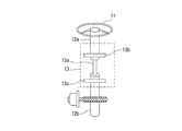
電動パワーステアリング装置3は、ステアリングホイール11を有し、このステアリングホイール11に運転者から作用される操舵力がステアリングシャフト12に伝達される。このステアリングシャフト12は、入力軸12aと出力軸12bとを有する。入力軸12aの一端はステアリングホイール11に連結され、他端は操舵トルクセンサ13を介して出力軸12bの一端に連結されている。
The electric
そして、出力軸12bに伝達された操舵力は、ユニバーサルジョイント14を介してロアシャフト15に伝達され、さらに、ユニバーサルジョイント16を介してピニオンシャフト17に伝達される。このピニオンシャフト17に伝達された操舵力はステアリングギヤ18を介してタイロッド19に伝達され、転舵輪としての前輪2FR及び2FLを転舵させる。ここで、ステアリングギヤ18は、ピニオンシャフト17に連結されたピニオン18aとこのピニオン18aに噛合するラック18bとを有するラックアンドピニオン形式に構成されている。したがって、ステアリングギヤ18は、ピニオン18aに伝達された回転運動をラック18bで車幅方向の直進運動に変換している。
The steering force transmitted to the
ステアリングシャフト12の出力軸12bには、操舵補助力を出力軸12bに伝達する操舵補助機構20が連結されている。この操舵補助機構20は、出力軸12bに連結した例えばウォームギヤ機構で構成される減速ギア21と、この減速ギア21に連結された操舵補助力を発生する例えば3相ブラシレスモータで構成される多相電動モータとしての3相電動モータ22とを備えている。
A
操舵トルクセンサ13は、ステアリングホイール11に付与されて入力軸12aに伝達された操舵トルクを検出する。この操舵トルクセンサ13は、図2に示すように、操舵トルクを、入力軸12a及び出力軸12b間に介挿した図示しないトーションバー13aの捩れ角変位に変換し、この捩れ角変位を入力軸12a側に配置した入力側回転角センサ13bと出力軸12b側に配置した出力側回転角センサ13cとの角度差に変換して検出するように構成されている。
The
なお、第1実施形態において、入力側回転角センサ13b及び出力側回転角センサ13cは相対的な回転角を検出するセンサである。
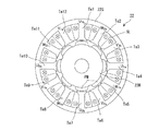
また、3相電動モータ22は、図3に示すように、内周面に内方に突出形成されてスロットSLを形成する磁極となるティースTeを有するステータ22Sと、このステータ22Sの内周側にティースTeと対向して回転自在に配置された永久磁石PMを表面に配置した8極の表面磁石型のロータ22Rとを有するSPMモータの構成を有する。ここで、ステータ22SのティースTeの数を相数×2n(nは2以上の整数)で例えばn=2に設定して8極、12スロットの構成としている。
In the first embodiment, the input side
Further, as shown in FIG. 3, the three-phase
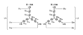
そして、ステータ22SのスロットSLに、図4に示す2系統で、その各々の同相の磁極がロータ磁石に対し同位相となる多相モータ巻線となる第1の3相モータ巻線L1と第2の3相モータ巻線L2とが巻装されている。第1の3相モータ巻線L1は、U相コイルU1a,U1b、V相コイルV1a,V1b及びW相コイルW1a,W1bの各一端が互いに接続されてスター結線とされている。さらに、U相コイルU1a,U1b、V相コイルV1a,V1b及びW相コイルW1a,W1bの各他端がモータ制御装置25に接続されて個別にモータ駆動電流I1u、I1v及びI1wが供給されている。
Then, in the slot SL of the
また、第2の3相モータ巻線L2は、U相コイルU2a,U2b、V相コイルV2a,V2b及びW相コイルW2a,W2bの各一端が互いに接続されてスター結線とされている。さらに、U相コイルU2a,U2b、V相コイルV2a,V2b及びW相コイルW2a,W2bの他端がモータ制御装置25に接続されて個別にモータ駆動電流I2u、I2v及びI2wが供給されている。
Further, the second three-phase motor winding L2 is star-connected by connecting one end of each of U-phase coils U2a and U2b , V-phase coils V2a and V2b, and W-phase coils W2a and W2b . Furthermore, the other ends of the U- phase coils U2a, U2b , the V-phase coils V2a, V2b and the W-phase coils W2a, W2b are connected to the
そして、第1の3相モータ巻線L1の各相コイル部U1a,U1b、V1a,V1b及びW1a,W1b並びに第2の3相モータ巻線L2の各相コイル部U2a,U2b、V2a,V2b及びW2a,W2bは各ティースTeを挟むスロットSLに通電電流の方向が同一方向となるように巻回されている。
このように第1の3相モータ巻線L1の各相コイル部U1a,U1b、V1a,V1b及びW1a,W1bと、第2の3相モータ巻線L2の各相コイル部U2a,U2b、V2a,V2b及びW2a,W2bと、が互いに異なる12本のティースTe1〜Te12に巻装されている。すなわち、12本のティースTe1〜Te12に、順次第1系統となる相コイルU1a,U1b、V1a,V1b及びW1a,W1bを反時計方向に順に同一の巻回方向で巻装し、次いで、第2系統となる相コイルU2a,U2b、V2a,V2b及びW2a,W2bを反時計方向に順に同一の巻回方向で巻装している。さらに、第1系統となる相コイルU1a,U1b、V1a,V1b及びW1a,W1bを反時計方向に順に同一の巻回方向で巻装し、最後に、第2系統となる相コイルU2a,U2b、V2a,V2b及びW2a,W2bを反時計方向に順に同一の巻回方向で巻装している。このため、第1の3相モータ巻線L1及び第2の3相モータ巻線L2の同相のコイル部がロータ22Rの各磁極の永久磁石PMで形成される同一の磁束に同時に鎖交することがないように巻装されている。したがって、第1の3相モータ巻線L1の各コイル部と第2の3相モータ巻線L2の各コイル部とで互いの磁気的な干渉を最小限に抑制する磁気回路を構成している。
Then, the phase coil portions U1a, U1b, V1a, V1b and W1a, W1b of the first three-phase motor winding L1, and the phase coil portions U2a, U2b, V2a, V2b of the second three-phase motor winding L2 and W2a and W2b are wound around slots SL sandwiching the teeth Te so that the directions of the energization currents are the same.
Thus, the phase coil portions U1a, U1b, V1a, V1b and W1a, W1b of the first three-phase motor winding L1, and the phase coil portions U2a, U2b, V2a, of the second three-phase motor winding L2 , V2b and W2a, and W2b, but are wound in different twelve teeth Te1~Te12 each other. That is, the twelve teeth Te 1~Te12, phase coils U1a whose forward upon one system, wound U 1 b, V1a, V1b and W1a, in order to W1b counterclockwise in the same winding direction, then the phase coils U2a that the two systems, U2b, V2a, V2b and W2a, are wound in sequence the W2b counterclockwise in the same winding direction. Further, the phase coils U1a to be the first system, U 1 b, V1a, V1b and W1a, wound in sequentially W1b counterclockwise in the same winding direction, finally, the phase coils U2a as a second system, U2b, V2a, V2b and W2a, are wound in sequence the W2b counterclockwise in the same winding direction. For this reason, the in-phase coil portions of the first three-phase motor winding L1 and the second three-phase motor winding L2 are simultaneously linked to the same magnetic flux formed by the permanent magnet PM of each magnetic pole of the
さらに、3相電動モータ22は、図5に示すように、ロータの回転位置を検出するレゾルバから構成された回転位置センサ23aを備えている。この回転位置センサ23aからの検出値がモータ電気角検出回路23に供給されてこのモータ電気角検出回路23でモータ電気角θmを検出する。以下、回転位置センサ23aを、「レゾルバ23a」と記載する場合がある。なお、回転位置センサ23aは、レゾルバに限らず、例えば、ロータリーエンコーダ等の他のセンサから構成してもよい。
Furthermore, as shown in FIG. 5, the three-phase
モータ制御装置25には、操舵トルクセンサ13で検出された操舵トルクT及び車速センサ26で検出された車速Vsが入力されるとともに、モータ電気角検出回路23から出力されるモータ電気角θmが入力される。
また、モータ制御装置25には、直流電流源としてのバッテリー27から直流電流が入力されている。ここで、バッテリー27の負極は接地され、その正極はエンジン始動を行うイグニッションスイッチ28(以下、「IGNスイッチ28」と記載する場合がある)を介してモータ制御装置25に接続されると共に、IGNスイッチ28を介さず直接、モータ制御装置25に接続されている。
The
In addition, a direct current is input to the
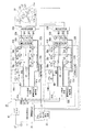
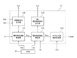
モータ制御装置25の具体的構成は、図5に示すように構成されている。すなわち、モータ制御装置25は、モータ電流指令値を演算する制御演算装置31と、この制御演算装置31から出力されるモータ電流指令値が個別に入力される第1及び第2のモータ駆動回路32A及び32Bと、これら第1及び第2のモータ駆動回路32A及び32Bの出力側と3相電動モータ22の第1及び第2の3相モータ巻線L1及びL2との間に介挿された第1及び第2のモータ電流遮断回路33A及び33Bとを備えている。
The specific configuration of the
制御演算装置31には、図5には図示を省略しているが、図1に示す操舵トルクセンサ13で検出した操舵トルクT及び車速センサ26で検出した車速Vsが入力されているとともに、図5に示すように、モータ電気角検出回路23から出力されるモータ電気角θmとが入力されている。さらに、電流検出回路34A及び34Bから出力される3相電動モータ22の第1の多相モータ巻線L1及び第2の多相モータ巻線L2の各相のコイルから出力されるモータ電流I1m(I1mu、I1mv、I1mw)及びI2m(I2mu、I2mv、I2mw)が入力されている。
Although not shown in FIG. 5, the steering torque T detected by the
以下、モータ電流I1m及びI2mを区別する必要が無い場合に、その検出値を「モータ電流検出値Im(Imu、Imv、Imw)」と記載する場合がある。
また、制御演算装置31には、図5に示すように、第1及び第2のモータ駆動回路32A及び32Bと第1及び第2のモータ電流遮断回路33A及び33Bとの間に設けられた電圧検出回路40A及び40Bで検出したモータ相電圧V1m(V1mu、V1mv、V1mw)及びV2m(V2mu、V2mv、V2mw)が入力されている。
Hereinafter, when there is no need to distinguish between the motor currents I1m and I2m, the detected value may be described as “motor current detected value Im (Imu, Imv, Imw)”.
In addition, as shown in FIG. 5, the control
以下、モータ相電圧V1m及びV2mを区別する必要が無い場合に、その検出値を「モータ電圧検出値Vm(Vmu、Vmv、Vmw)」と記載する場合がある。
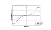
制御演算装置31では、第1及び第2のモータ駆動回路32A及び32Bの正常時には操舵トルクT及び車速Vsをもとに予め設定された図6に示す正常時操舵補助電流指令値算出マップを参照して操舵補助電流指令値I1*及びI2*を算出する。また、制御演算装置31では、第1及び第2のモータ駆動回路32A又は32Bの異常時には操舵トルクT及び車速Vsをもとに予め設定された図7に示す異常時操舵補助電流指令値算出マップを参照して操舵補助電流指令値I1*及びI2*を算出する。
Hereinafter, when there is no need to distinguish between the motor phase voltages V1m and V2m, the detected value may be described as “motor voltage detected value Vm (Vmu, Vmv, Vmw)”.
In the control
また、制御演算装置31では、算出した操舵補助電流指令値I1*及びI2*とモータ電気角θmとに基づいてd−q座標系の目標d軸電流指令値Id*及び目標q軸電流指令値Iq*を算出する。また、制御演算装置31は、算出したd軸電流指令値Id*及びq軸電流指令値Iq*をdq相−3相変換してU相電流指令値Iu*、V相電流指令値Iv*及びW相電流指令値Iw*を算出する。そして、制御演算装置31は、算出したU相電流指令値Iu*、V相電流指令値Iv*及びW相電流指令値Iw*と電流検出回路34A及び34Bで検出した電流検出値の相毎の加算値との電流偏差ΔIu、ΔIv及びΔIwを算出する。なおさらに、制御演算装置31は、算出した電流偏差ΔIu、ΔIb及びΔIwについて例えばPI制御演算又はPID制御演算を行って第1及び第2のモータ駆動回路32A及び32Bに対する3相の電圧指令値V1*及びV2*を算出し、算出した3相の電圧指令値V1*及びV2*を第1及び第2のモータ駆動回路32A及び32Bに出力する。
Further, in the control
また、制御演算装置31には、第1及び第2のモータ電流遮断回路33A及び33Bと3相電動モータ22の第1及び第2の3相モータ巻線L1及びL2との間に設けられた第1及び第2の異常検出回路35A及び35Bで検出したモータ電流検出値I1mu、I1mv、I1mw及びI2mu、I2mv、I2mwが入力されている。
そして、制御演算装置31は、入力されるモータ電流検出値I1mu〜I1mw及びI2mu〜I2mwと自身が算出した各相電流指令値Iu*、Iv*及びIw*とを比較して後述する第1及び第2のインバータ回路42A及び42Bを構成するスイッチング素子としての電界効果トランジスタ(FET)Q1〜Q6のオープン故障及びショート故障を検出する異常検出部31aを備えている。
Further, the control
Then, the control
この異常検出部31aでは、第1及び第2のインバータ回路42A及び42Bを構成する電界効果トランジスタ(FET)のオープン故障又はショート故障を検出したときに、異常を検出した第1及び第2のモータ駆動回路32A又は32Bのゲート駆動回路41A又は41Bに対して論理値"1"の異常検出信号SAa又はSAbを出力する。
第1及び第2のモータ駆動回路32A及び32Bのそれぞれは、制御演算装置31から出力される3相の電圧指令値V1*及びV2*が入力されてゲート信号を形成するとともに、異常時電流制御部41aを有するゲート駆動回路41A及び41Bと、これらゲート駆動回路41A及び41Bから出力されるゲート信号が入力される第1及び第2のインバータ回路42A及び42Bとを備えている。
In the
Each of the first and second
ゲート駆動回路41A及び41Bのそれぞれは、制御演算装置31から電圧指令値V1*及びV2*が入力されると、これら電圧指令値V1*及びV2*と三角波のキャリア信号Scとをもとにパルス幅変調(PWM)した6つのゲート信号を形成し、これらゲート信号を第1及び第2のインバータ回路42A及び42Bに出力する。
また、ゲート駆動回路41Aは、制御演算装置31から入力される異常検出信号SAaが論理値"0"(正常)であるときには、第1のモータ電流遮断回路33Aに対してハイレベルの3つのゲート信号を出力するとともに、第1の電源遮断回路44Aに対してハイレベルの2つのゲート信号を出力する。さらに、ゲート駆動回路41Aは、異常検出信号SAaが論理値"1"(異常)であるときには、異常時電流制御部41aで、第1のモータ電流遮断回路33Aに対してローレベルの3つのゲート信号を同時に出力し、モータ電流を遮断するとともに、第1の電源遮断回路44Aに対してローレベルの2つのゲート信号を同時に出力し、バッテリー電力を遮断する。
When the voltage command values V1 * and V2 * are input from the control
Further, when the abnormality detection signal SAa input from the control
同様に、ゲート駆動回路41Bは、制御演算装置31から入力される異常検出信号SAbが論理値"0"(正常)であるときには、第2のモータ電流遮断回路33Bに対してハイレベルの3つのゲート信号を出力するとともに、第2の電源遮断回路44Bに対してハイレベルの2つのゲート信号を出力する。さらに、ゲート駆動回路41Bは、異常検出信号SAbが論理値"1"(異常)であるときには、異常時電流制御部41aで、第2のモータ電流遮断回路33Bに対してローレベルの3つのゲート信号を同時に出力し、モータ電流を遮断するとともに、第2の電源遮断回路44Bに対してローレベルの2つのゲート信号を同時に出力し、バッテリー電力を遮断する。
Similarly, when the abnormality detection signal SAb input from the control
第1及び第2のインバータ回路42A及び42Bのそれぞれは、ノイズフィルタ43、第1及び第2の電源遮断回路44A及び44Bを介してバッテリー27のバッテリー電流が入力され、入力側に平滑用の電解コンデンサCA及びCBが接続されている。
これら第1及び第2のインバータ回路42A及び42Bは、6個のスイッチング素子としての電界効果トランジスタ(FET)Q1〜Q6を有し、2つの電界効果トランジスタを直列に接続した3つのスイッチングアームSAu、SAv及びSAwを並列に接続した構成を有する。そして、各電界効果トランジスタQ1〜Q6のゲートにゲート駆動回路41A及び41Bから出力されるゲート信号が入力されることにより、各スイッチングアームSAu、SAv及びSAwの電界効果トランジスタ間からU相電流Iu、V相電流Iv及びW相電流Iwが第1及び第2のモータ電流遮断回路33A及び33Bを介して3相電動モータ22の第1及び第2の3相モータ巻線L1及びL2に出力される。
In each of the first and
These first and
また、図示しないが第1及び第2のインバータ回路42A及び42Bの各スイッチングアームSAu、SAv及びSAwと接地との間に介挿されたシャント抵抗の両端電圧が電流検出回路34A及び34Bに入力され、これら電流検出回路34A及び34Bでモータ電流I1m(I1mu〜I1mw)及びI2m(I2mu〜I2mw)が検出される。
また、第1のモータ電流遮断回路33Aは、3つの電流遮断用の電界効果トランジスタQA1、QA2及びQA3を有する。電界効果トランジスタQA1のソースが第1のインバータ回路42AのスイッチングアームSAuのトランジスタQ1及びQ2の接続点に接続され、ドレインが第1の異常検出回路35Aを介して第1の3相モータ巻線L1のU相コイルL1uに接続されている。また、電界効果トランジスタQA2のソースが第1のインバータ回路42AのスイッチングアームSAvのトランジスタQ3及びQ4の接続点に接続され、ドレインが第1の異常検出回路35Aを介して第1の3相モータ巻線L1のV相コイルL1vに接続されている。さらに、電界効果トランジスタQA3のソースが第1のインバータ回路42AのスイッチングアームSAwのトランジスタQ5及びQ6の接続点に接続され、ドレインが第1の異常検出回路35Aを介して第1の3相モータ巻線L1のW相コイルL1wに接続されている。
Although not shown, the voltage across the shunt resistor inserted between the switching arms SAu, SAv and SAw of the first and
The first motor current cut-
また、第2のモータ電流遮断回路33Bは、3つの電流遮断用の電界効果トランジスタQB1、QB2及びQB3を有する。電界効果トランジスタQB1のソースが第2のインバータ回路42BのスイッチングアームSBuのトランジスタQ1及びQ2の接続点に接続され、ドレインが第2の異常検出回路35Bを介して第2の3相モータ巻線L2のU相コイルL2uに接続されている。また、電界効果トランジスタQB2のソースが第2のインバータ回路42BのスイッチングアームSBvのトランジスタQ3及びQ4の接続点に接続され、ドレインが第2の異常検出回路35Bを介して第2の3相モータ巻線L2のV相コイルL2vに接続されている。さらに、電界効果トランジスタQB3のソースが第2のインバータ回路42BのスイッチングアームSBwのトランジスタQ5及びQ6の接続点に接続され、ドレインが第2の異常検出回路35Bを介して第2の3相モータ巻線L2のW相コイルL2wに接続されている。
The second motor current cut-
そして、第1及び第2のモータ電流遮断回路33A及び33Bの電界効果トランジスタQA1〜QA3及びQB1〜QB3がそれぞれの寄生ダイオードDのカソードを第1及び第2のインバータ回路42A及び42B側として各々が同一向きに接続されている。
また、第1及び第2の電源遮断回路44A及び44Bのそれぞれは、2つの電界効果トランジスタ(FET)QC1,QC2及びQD1,QD2がドレイン同士を接続して寄生ダイオードが逆向きとなる直列回路構成を有する。そして、電界効果トランジスタQC1及びQD1のソースが互いに接続されてノイズフィルタ43の出力側に接続され、電界効果トランジスタQC2及びQD2のソースが第1及び第2のインバータ回路42A及び42Bの各電界効果トランジスタQ1,Q2及びQ3のソースに接続されている。
The field effect transistors QA1 to QA3 and QB1 to QB3 of the first and second motor current cut-
Each of the first and second
(モータ電気角検出回路23)
次に、第1実施形態に係るモータ電気角検出回路23の具体的な構成を説明する。
第1実施形態のモータ電気角検出回路23は、図8に示すように、メインモータ電気角検出回路23bと、サブモータ電気角検出回路23cと、電気角選択部23dと、RAM50と、ROM51とを備えている。
メインモータ電気角検出回路23bは、角度演算部60と、レゾルバ異常診断部61とを備えている。
(Motor electrical angle detection circuit 23)
Next, a specific configuration of the motor electrical
As shown in FIG. 8, the motor electrical
The main motor electrical
角度演算部60は、レゾルバ23aから出力される3相電動モータ22の回転角に応じたsin信号及びcos信号に基づいて第1のモータ電気角θm1を演算する。そして、演算した第1のモータ電気角θm1を電気角選択部23dに出力する。
レゾルバ異常診断部61は、レゾルバ23aの異常を検出し、異常検出信号SArを出力する。
The
The resolver
また、サブモータ電気角検出回路23cには、図5では図示省略しているが、出力側回転角センサ13cから出力される出力軸回転角検出値θosと、電流検出回路34A及び34Bから出力される電流検出値Imと、IGNスイッチ28から出力されるIGNスイッチ28のON/OFFを示すイグニッション信号IGNとが入力されている。加えて、角度演算部60からの第1のモータ電気角θm1と、レゾルバ異常診断部61からの異常検出信号SArとが入力されている。
Although not shown in FIG. 5, the sub motor electrical
このサブモータ電気角検出回路23cは、相対オフセット量推定部62と、モータ電気角推定部63とを備えている。
相対オフセット量推定部62は、モータ電気角θmの原点θmd(以下、「モータ電気角原点θmd」と記載する場合がある)と出力軸回転角検出値θosの基準値θosrとの相対オフセット量θoffを推定する。そして、推定した相対オフセット量θoffをモータ電気角推定部63に出力する。
The sub motor electrical
The relative offset
モータ電気角推定部63は、出力側回転角センサ13cの検出した出力軸回転角検出値θosと、ROM51に予め記憶された減速ギア21の減速比RGrと、3相電動モータ22のロータ22Rの極対数Pと、相対オフセット量推定部62で推定した相対オフセット量θoffとに基づきモータ電気角推定値θmeを算出する。そして、算出したモータ電気角推定値θmeを第2のモータ電気角θm2として電気角選択部23dに出力する。
The motor
具体的に、モータ電気角推定部63は、下式(1)にしたがって、モータ電気角推定値θmeを算出する。
θme=θos×RGr×P+θoff ・・・(1)
即ち、出力軸回転角検出値θosに対して減速比RGr及び極対数Pを乗算し、この乗算結果に対して相対オフセット量θoffを加算することでモータ電気角推定値θmeを算出する。
Specifically, the motor electrical
θme = θos × RGr × P + θoff (1)
That is, the motor electrical angle estimated value θme is calculated by multiplying the output shaft rotation angle detection value θos by the reduction ratio RGr and the pole pair number P, and adding the relative offset amount θoff to the multiplication result.
電気角選択部23dは、メインモータ電気角検出回路23bのレゾルバ異常診断部61から出力される異常検出信号SArが異常なしを表す論理値"0"であるときに、メインモータ電気角検出回路23bから出力される第1のモータ電気角θm1を選択してモータ電気角θmとして前述した制御演算装置31に出力する。一方、異常検出信号SArが異常ありを表す論理値"1"であるときに、サブモータ電気角検出回路23cから出力される第2のモータ電気角θm2を選択してモータ電気角θmとして制御演算装置31に出力する。
When the abnormality detection signal SAr output from the resolver
(相対オフセット量推定部62)
次に、第1実施形態に係る相対オフセット量推定部62の具体的な構成について説明する。
第1実施形態の相対オフセット量推定部62は、図9に示すように、第1相対オフセット量推定部70と、第2相対オフセット量推定部71と、相対オフセット量選択部72とを備えている。
(Relative offset amount estimation unit 62)
Next, a specific configuration of the relative offset
As shown in FIG. 9, the relative offset
第1相対オフセット量推定部70は、レゾルバ23a及び角度演算部60が正常時に、出力側回転角センサ13cで検出される出力軸回転角検出値θosと、メインモータ電気角検出回路23bで検出されるモータ電気角検出値θm1とに基づき第1の相対オフセット量θoff1を推定する。そして、推定した第1の相対オフセット量θoff1をRAM50に記憶する。
The first relative offset
ここで、レゾルバ23a及び角度演算部60が正常時は、モータ電気角の原点θmdが解るので、出力軸回転角検出値の基準値θosrとの相対オフセット量を容易に推定することが可能である。
なお、基準値θosrは、システム起動時(IGNスイッチ28がOFFからONになった時)の出力軸回転角検出値に極対数Pと減速比RGrとを乗算したものである。
Here, when the
The reference value θosr is obtained by multiplying the detected value of the output shaft rotation angle when the system is started (when the
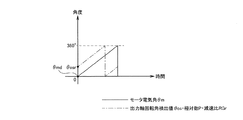
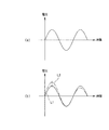
また、モータ電気角θmを出力軸回転角検出値θos・極対数P・減速比RGrで補うためには、モータ電気角の原点θmd(0度)と出力軸回転角検出値の基準値θosrとを一致させる必要がある。例えば、図10中に示すように、基準値θosrと原点θmdとが一致していない場合、同図中の一点鎖線に示すように、同図中の実線に示すモータ電気角θmに対して出力軸回転角検出値θos・極対数P・減速比RGr(基準値θosrからの変位量)に角度誤差が生じる。そのため、実際のモータ電気角θmに対して大きなずれが生じることになる。 Further , in order to supplement the motor electrical angle θm with the output shaft rotation angle detection value θos , the number of pole pairs P, and the reduction ratio RGr , the motor electrical angle origin θmd (0 degree) and the reference value θosr of the output shaft rotation angle detection value Need to match. For example, as shown in FIG. 10, when the reference value θosr and the origin θmd do not coincide with each other, the output is made with respect to the motor electrical angle θm indicated by the solid line in the figure, as indicated by the one-dot chain line in the figure. An angle error occurs in the shaft rotation angle detection value θos , the number of pole pairs P, and the reduction ratio RGr (displacement from the reference value θosr). For this reason, a large deviation occurs from the actual motor electrical angle θm.
そのため、モータ電気角の原点θmdに対して、出力軸回転角検出値の基準値θosrがどれだけずれているかを相対オフセット量として求めておき、モータ電気角を推定時は相対オフセット量を加える(相対オフセット量で補正する)必要がある。
第2相対オフセット量推定部71は、イグニッションスイッチがOFF状態となるシステム停止後からIGNスイッチ28が再びON状態となるシステム再起動後のレゾルバ異常診断部61による初期診断にて異常検出信号SArが異常ありを示す値であったときに、第2の相対オフセット量θoff2を推定する。そして、推定した第2の相対オフセット量θoff2をRAM50に記憶する。なお、第1実施形態のレゾルバ異常診断部61は、IGNスイッチ28がON状態となってシステムが起動した直後に診断を行うようになっている。
Therefore, how much the reference value θosr of the output shaft rotation angle detection value is deviated from the origin θmd of the motor electrical angle is obtained as a relative offset amount, and the relative offset amount is added when estimating the motor electrical angle ( It is necessary to correct with a relative offset amount).
The second relative offset
ここで、前回のシステム起動中に例えばレゾルバ23aが故障していた場合、又はシステム停止中に例えばレゾルバ23aに故障が生じていた場合、今回のシステム起動後の初期診断にて異常と診断される。この場合、前回のシステム起動中に得た角度データ等が全て失われてしまう。また、システム停止中に、ドライバがステアリングホイール11を操作する場合もある。
したがって、システム再起動後の初期診断で異常と診断された場合は、モータ電気角原点θmdを推定すると共に、推定したモータ電気角原点θmdに基づき第2の相対オフセット量θoff2を推定する必要がある。
Here, when the
Therefore, when an abnormality is diagnosed in the initial diagnosis after the system is restarted, it is necessary to estimate the motor electrical angle origin θmd and to estimate the second relative offset amount θoff2 based on the estimated motor electrical angle origin θmd. .
(第2相対オフセット量推定部71)
次に、第1実施形態に係る第2相対オフセット量推定部71の具体的な構成について説明する。
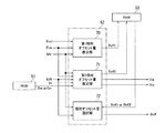
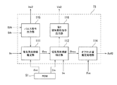
第1実施形態の第2相対オフセット量推定部71は、図11に示すように、高調波指令出力部110と、電気角初期値推定部111と、電気角初期値補正部112と、第1磁気飽和指令出力部113と、オフセット量推定処理部114とを備えている。
(Second relative offset amount estimation unit 71)
Next, a specific configuration of the second relative offset
As shown in FIG. 11, the second relative offset
高調波指令出力部110は、システム再起動後の初期診断において異常検出信号SArが異常ありを示す値となったときに、3相電動モータ22のロータ22Rが回転せずかつステータ22Sに磁気飽和が生じない程度の高調波の電圧指令の出力指令である第1電圧出力指令Voi1を制御演算装置31に出力する。
第1実施形態の制御演算装置31は、第1電圧出力指令Voi1の入力に応じて高調波電圧による通電を行う電圧指令を生成し、生成した電圧指令をゲート駆動回路41A及び41Bに出力する。これにより、第1及び第2のインバータ回路42A及び42Bを介して、3相電動モータ22への高調波電圧による通電が行われる。
When the abnormality detection signal SAr becomes a value indicating abnormality in the initial diagnosis after system restart, the harmonic
The control
電気角初期値推定部111は、高調波電圧の印加に応じて3相電動モータ22に流れる電流の電流検出値Imを電流検出回路34A及び34Bを介して取得し、取得した電流検出値Imのピーク値である第1電流ピーク値Imp1を検出する。
ここで、高調波電圧の印加に応じて3相電動モータ22にはモータ電気角θmに依存した電流が流れる。具体的に、この電流のピーク値である第1電流ピーク値Imp1はモータ電気角の情報を有している。
The electrical angle initial
Here, a current depending on the motor electrical angle θm flows through the three-phase
そこで、第1実施形態では、第1電流ピーク値Im1とモータ電気角θmの情報θmi(以下、「モータ電気角情報θmi」と記載する場合がある)との関係を予めマップとして用意し、このマップ(以下、「電気角情報マップ」と記載する場合がある)をROM51に記憶している。
電気角初期値推定部111は、検出した第1電流ピーク値Imp1からROM51に記憶された電気角情報マップを参照してモータ電気角情報θmiを読み出し、読み出したモータ電気角情報θmiに基づきモータ電気角初期値θmsを推定する。そして、推定したモータ電気角初期値θmsを電気角初期値補正部112に出力する。
Therefore, in the first embodiment, a relationship between the first current peak value Im1 and the motor electrical angle θm information θmi (hereinafter sometimes referred to as “motor electrical angle information θmi”) is prepared in advance as a map. A map (hereinafter sometimes referred to as “electrical angle information map”) is stored in the
The electrical angle initial
電気角初期値補正部112は、モータ電気角初期値θmsの入力に応じて、3相電動モータ22のロータ22Rが回転せずかつステータ22Sに磁気飽和が生じるほど大きい電圧指令(以下、「第1磁気飽和電圧指令」と記載する場合がある)の出力指示を第1磁気飽和指令出力部113に出力する。
第1磁気飽和指令出力部113は、電気角初期値補正部112からの出力指示に応じて、第1磁気飽和電圧指令の出力指令である第1飽和電圧出力指令Vsi1を制御演算装置31に出力する。
In response to the input of the motor electrical angle initial value θms, the electrical angle initial
The first magnetic saturation
第1実施形態の制御演算装置31は、第1飽和電圧出力指令Vsi1の入力に応じて第1磁気飽和電圧指令を生成し、生成した第1磁気飽和電圧指令をゲート駆動回路41A及び41Bに出力する。これにより、第1及び第2のインバータ回路42A及び42Bを介して、3相電動モータ22への磁気飽和が生じるほど大きい高調波電圧(以下、「第1磁気飽和電圧」と記載する場合がある)による通電が行われる。
The control
電気角初期値補正部112は、第1磁気飽和電圧の印加に応じて3相電動モータ22に流れる電流の電流検出値Imを電流検出回路34A及び34Bを介して取得し、取得した電流検出値Imのピーク値である第2電流ピーク値Imp2を検出する。
ここで、第1磁気飽和電圧を印加した場合も3相電動モータ22にモータ電気角θmに依存した電流が流れる。この電流のベクトルの大きさはN極方向を向くときの方がS極方向を向くときよりも大きくなる特性を有している。即ち、この電流の第2電流ピーク値Impは、第1電流ピーク値Im1のベクトルの向く方向(N極方向及びS極方向)を判別する情報を有しており、この情報に基づきモータ電気角初期値θmsを補正することが可能である。
The electrical angle initial
Here, even when the first magnetic saturation voltage is applied, a current depending on the motor electrical angle θm flows through the three-phase
そこで、第1実施形態では、第2電流ピーク値Im2とモータ電気角初期値θmsの補正情報Cm(以下、「モータ電気角補正情報Cm」と記載する場合がある)との関係を予めマップとして用意し、このマップ(以下、「補正情報マップ」と記載する場合がある)をROM51に記憶している。
電気角初期値補正部112は、検出した第2電流ピーク値Imp2からROM51に記憶された補正情報マップを参照してモータ電気角補正情報Cmを読み出し、読み出したモータ電気角補正情報Cmに基づきモータ電気角初期値θmsを補正する。そして、補正後のモータ電気角初期値θmscをオフセット量推定処理部114に出力する。
Therefore, in the first embodiment, the relationship between the second current peak value Im2 and the correction information Cm of the motor electric angle initial value θms (hereinafter sometimes referred to as “motor electric angle correction information Cm”) is used as a map in advance. This map is prepared and stored in the ROM 51 (hereinafter sometimes referred to as “correction information map”).
The electrical angle initial
オフセット量推定処理部114は、補正後のモータ電気角初期値θmscに基づきモータ電気角原点θmdを推定し、このモータ電気角原点θmdとシステム再起動時の出力軸回転角検出値の基準値θosrとに基づき第2の相対オフセット量θoff2を推定する。そして、推定した第2の相対オフセット量θoff2をRAM50に記憶する。
相対オフセット量選択部72は、システム起動中に異常検出信号SArが異常ありを示す値となった場合に、第1の相対オフセット量θoff1を選択し、システム再起動後の初期診断で異常検出信号SArが異常ありを示す値となった場合に、第2の相対オフセット量θoff2を選択する。そして、第1の相対オフセット量θoff1及び第2の相対オフセット量θoff2のうち選択した方をRAM50から読み出し、相対オフセット量θoffとしてモータ電気角推定部63に出力する。
The offset amount
The relative offset
(動作)
次に、上記第1実施形態の動作を説明する。
IGNスイッチ28がオフ状態であって車両1が停止していると共に、操舵補助制御処理も停止している作動停止状態であるときには、モータ制御装置25の制御演算装置31及びモータ電気角検出回路23が非作動状態となっている。
このため、制御演算装置31及びモータ電気角検出回路23で実行される各種処理は停止されている。この状態では、3相電動モータ22は作動を停止しており、ステアリング機構への操舵補助力の出力を停止している。
(Operation)
Next, the operation of the first embodiment will be described.
When the
For this reason, the various processes performed by the control
この作動停止状態からIGNスイッチ28をオン状態とすると、制御演算装置31及びモータ電気角検出回路23が作動状態となり、モータ電気角θmの検出処理、操舵補助制御処理等の各種処理を開始する。このとき、レゾルバ23a及び角度演算部60が正常であるものとする。
このときには、異常検出信号SArが異常なしを表す値となり、電気角選択部23dは、角度演算部60で演算した第1のモータ電気角θm1をモータ電気角θmとして制御演算装置31に出力する。
When the
At this time, the abnormality detection signal SAr becomes a value indicating that there is no abnormality, and the electrical
制御演算装置31では、このモータ電気角θmに基づいてd軸電流指令値Id*及びq軸電流指令値Iq*を算出する。そして、d軸電流指令値Id*及びq軸電流指令値Iq*に基づき第1及び第2のモータ駆動回路32A及び32Bに対する3相の電圧指令値V1*及びV2*を算出し、算出した3相の電圧指令値V1*及びV2*を第1及び第2のモータ駆動回路32A及び32Bに出力する。これにより、第1及び第2のモータ駆動回路32A及び32Bによって第1及び第2のインバータ回路42A及び42Bが駆動制御され3相電動モータ22が駆動制御(転流制御)される。
The control
一方、レゾルバ23a及び角度演算部60が正常時は、サブモータ電気角検出回路23cの相対オフセット量推定部62において、第1の相対オフセット量θoff1の推定処理が行われる。即ち、正常時の出力側回転角センサ13cで検出される出力軸回転角検出値θosと、メインモータ電気角検出回路23bから出力されるモータ電気角θmとに基づき第1の相対オフセット量θoff1を推定し、推定した第1の相対オフセット量θoff1をRAM50に記憶する。
On the other hand, when the
そして、第1実施形態の相対オフセット量推定部62は、レゾルバ23a及び角度演算部60が正常時に、RAM50に記憶された第1の相対オフセット量θoff1を相対オフセット量θoffとしてモータ電気角推定部63に出力する。
モータ電気角推定部63は、レゾルバ23a及び角度演算部60の正常時において、出力側回転角センサ13cで検出される出力軸回転角検出値θosと、第1の相対オフセット量θoff1と、減速比RGr(例えば、20.5)と、磁極対(例えば、4)とからモータ電気角推定値θmeを算出する。そして、モータ電気角推定値θmeを第2のモータ電気角θm2として電気角選択部23dに出力する。
The relative offset
When the
その後、システム起動中にレゾルバ23a及び角度演算部60の少なくとも一方に故障が発生して、異常検出信号SArが異常ありを表す値になると、電気角選択部23dは、サブモータ電気角検出回路23cから入力される第2のモータ電気角θm2をモータ電気角θmとして制御演算装置31に出力する。
これにより、制御演算装置31では、サブモータ電気角検出回路23cで推定した第2のモータ電気角θm2に基づき3相電動モータ22を駆動制御(転流制御)する。
Thereafter, when a failure occurs in at least one of the
Thereby, in the control
引き続き、IGNスイッチ28が一旦OFF状態となってシステムが停止し、その後、再びIGNスイッチ28がON状態となってシステムが再起動したとする。
この場合、システム再起動後のレゾルバ異常診断部61による初期診断によって異常検出信号SArが異常ありを表す値となり、相対オフセット量推定部62において、第2の相対オフセット量θoff2の推定処理が実施される。
Subsequently, it is assumed that the
In this case, the abnormality detection signal SAr becomes a value indicating that there is an abnormality by the initial diagnosis by the resolver
具体的に、相対オフセット量推定部62は、まず、高調波指令出力部110において、第1電圧出力指令Voi1を制御演算装置31に出力して、3相電動モータ22に対して、ロータ22Rが回転せずかつステータ22Sに磁気飽和が生じない程度の高調波電圧を印加させる。例えば、図12(a)に示すような波形の高調波電圧を印加したとする。次に、電気角初期値推定部111において、高調波電圧の印加に応じて3相電動モータ22に流れる電流の電流検出値Imから第1電流ピーク値Imp1を検出する。例えば、図12(b)の実線L1に示すような応答電流が流れたとして、同図中の「○」で示すピーク値を第1電流ピーク値Imp1として検出する。電気角初期値推定部111は、検出した第1電流ピーク値Imp1からROM51に記憶された電気角情報マップを参照してモータ電気角情報θmiを取得し、取得したモータ電気角情報θmiに基づきモータ電気角初期値θmsを推定する。
Specifically, the relative offset
引き続き、相対オフセット量推定部62は、第1磁気飽和指令出力部113において、第1飽和電圧出力指令Vsi1を制御演算装置31に出力して、3相電動モータ22に対して、ロータ22Rが回転せずかつステータ22Sの磁気飽和が生じる程度の高調波電圧(第1磁気飽和電圧)を印加させる。そして、電気角初期値補正部112において、第1磁気飽和電圧の印加に応じて3相電動モータ22に流れる電流の電流検出値Imから第2電流ピーク値Imp2を検出する。例えば、図12(b)の一点鎖線L2に示すような応答電流が流れたとして、同図中の「◇」で示すピーク値を第2電流ピーク値Imp2として検出する。電気角初期値補正部112は、検出した第2電流ピーク値Imp2からROM51に記憶された補正情報マップを参照してモータ電気角補正情報Cmを取得し、取得したモータ電気角補正情報Cmに基づきモータ電気角初期値θmsを補正する。
Subsequently, the relative offset
引き続き、相対オフセット量推定部62は、オフセット量推定処理部114において、補正後のモータ電気角初期値θmscに基づきモータ電気角原点θmdを推定し、このモータ電気角原点θmdと、システム再起動時に取得した出力軸回転角検出値の基準値θosrとに基づき第2の相対オフセット量θoff2を推定する。そして、推定した第2の相対オフセット量θoff2を、RAM50に記憶する。
Subsequently, the relative offset
さらに、相対オフセット量推定部62は、相対オフセット量選択部72において、システム再起動後の初期診断によって異常検出信号SArが異常ありを表す値となったことから、RAM50から第2の相対オフセット量θoff2を読み出し、読み出した第2の相対オフセット量θoff2を相対オフセット量θoffとしてモータ電気角推定部63に出力する。
Further, the relative offset
これにより、モータ電気角推定部63は、出力側回転角センサ13cで検出される出力軸回転角検出値θosと、第2の相対オフセット量θoff2と、減速比RGr(例えば、20.5)と、磁極対(例えば、4)とからモータ電気角推定値θmeを算出する。そして、算出したモータ電気角推定値θmeを第2のモータ電気角θm2として電気角選択部23dに出力する。
As a result, the motor electrical
電気角選択部23dは、異常検出信号SArが異常ありを表す値であることから、サブモータ電気角検出回路23cから入力される第2のモータ電気角θm2をモータ電気角θmとして制御演算装置31に出力する。
これにより、制御演算装置31では、サブモータ電気角検出回路23cで推定した第2のモータ電気角θm2に基づき3相電動モータ22を駆動制御(転流制御)する。
Since the abnormality detection signal SAr has a value indicating that there is an abnormality, the electrical
Thereby, in the control
ここで、電気角初期値推定部111がモータ電気角初期値推定部に対応し、モータ電気角推定部63がモータ電気角推定部に対応し、制御演算装置31及びモータ電気角検出回路23がモータ駆動制御部に対応する。
また、操舵トルクセンサ13がトルク検出部に対応し、出力側回転角センサ13cがステアリング舵角検出部に対応し、3相電動モータ22が多相電動モータに対応し、レゾルバ23a及び角度演算部60がモータ電気角検出部に対応する。
また、第1及び第2のインバータ回路42A及び42Bがモータ駆動回路に対応し、制御演算装置31が制御演算装置に対応し、レゾルバ異常診断部61が、異常診断部に対応する。
Here, the electrical angle initial
Further, the
The first and
(第1実施形態の効果)
(1)第1実施形態に係るモータ制御装置25は、電気角初期値推定部111が、システム再起動後の初期診断において、操舵補助力を発生する3相電動モータ22のモータ電気角θmを検出するレゾルバ23a及び角度演算部60の少なくとも一方が異常と診断されると、3相電動モータ22へのモータ駆動信号(高調波電圧)の入力に応じた3相電動モータ22の応答出力(応答電流)に基づきモータ電気角初期値θmsを推定する。モータ電気角推定部63が、出力軸回転角検出値θosと、モータ電気角初期値θms(に基づき推定した第2の相対オフセット量θoff2)とに基づきモータ電気角θmを推定する。制御演算装置31及びモータ電気角検出回路23が、レゾルバ23a及び角度演算部60が正常時はこれらで検出した第1のモータ電気角θm1に基づき3相電動モータ22を駆動制御する。一方、システム再起動後の初期診断においてレゾルバ23a及び角度演算部60の少なくとも一方が異常時はモータ電気角推定部63で推定した第2のモータ電気角θm2に基づき3相電動モータ22を駆動制御する。
(Effect of 1st Embodiment)
(1) In the
この構成であれば、システム再起動後の初期診断でレゾルバ23a及び角度演算部60の少なくとも一方が異常と診断された場合に、3相電動モータ22へのモータ駆動信号の入力に応じた3相電動モータ22の応答出力に基づきモータ電気角初期値θmsを推定し、推定したモータ電気角初期値θmsと出力軸回転角検出値θosとに基づきモータ電気角θmを推定することが可能である。
これにより、レゾルバ23a及び角度演算部60の少なくとも一方が異常と診断されてから一旦システムが停止した後にシステムが再起動した場合や、システム停止中に異常が発生した場合などでもシステム再起動後に3相電動モータ22を正常時と遜色なく駆動することが可能となる。
With this configuration, when at least one of the
As a result, even if at least one of the
(2)第1実施形態に係るモータ制御装置25は、操舵トルクセンサ13がステアリング機構に伝達される操舵トルクTを検出する。出力側回転角センサ13cがステアリングの舵角(出力軸回転角検出値θos)を検出する。3相電動モータ22が操舵補助力を発生する。レゾルバ23a及び角度演算部60が3相電動モータ22のモータ電気角θmを検出する。第1及び第2のインバータ回路42A及び42Bが、3相電動モータ22に駆動電流を供給する。制御演算装置31が、操舵トルクセンサ13で検出した操舵トルクTとレゾルバ23a及び角度演算部60で検出したモータ電気角θmとに基づき第1及び第2のインバータ回路42A及び42Bを駆動制御する。
(2) In the
加えて、レゾルバ異常診断部61が、レゾルバ23a及び角度演算部60の異常を診断する。電気角初期値推定部111が、システム再起動後の初期診断において、操舵補助力を発生する3相電動モータ22のモータ電気角θmを検出するレゾルバ23a及び角度演算部60の少なくとも一方が異常と診断されると、3相電動モータ22へのモータ駆動信号(高調波電圧)の入力に応じた3相電動モータ22の応答出力(応答電流)に基づきモータ電気角初期値θmsを推定する。
In addition, the resolver
さらに、モータ電気角推定部63が、出力側回転角センサ13cで検出した出力軸回転角検出値θosと電気角初期値推定部111で推定したモータ電気角初期値θms(に基づき推定した第2の相対オフセット量θoff2)とに基づきモータ電気角θmを推定する。制御演算装置31が、システム再起動後のレゾルバ異常診断部61による初期診断でレゾルバ23a及び角度演算部60の少なくとも一方が異常と診断されると、操舵トルクセンサ13で検出した操舵トルクTとモータ電気角推定部63で推定したモータ電気角推定値θme(第2のモータ電気角θm2)とに基づき第1及び第2のインバータ回路42A及び42Bを駆動制御する。
Further, the motor electrical
この構成であれば、システム再起動後の初期診断でレゾルバ23a及び角度演算部60の少なくとも一方が異常と診断された場合に、3相電動モータ22へのモータ駆動信号の入力に応じた3相電動モータ22の応答出力に基づきモータ電気角初期値θmsを推定し、推定したモータ電気角初期値θmsと出力軸回転角検出値θosとに基づきモータ電気角θmを推定することが可能である。
これにより、レゾルバ23a及び角度演算部60の少なくとも一方が異常と診断されてから一旦システムが停止した後にシステムが再起動した場合や、システム停止中に異常が発生した場合などでもシステム再起動後に3相電動モータ22を正常時と遜色なく駆動することが可能となる。
With this configuration, when at least one of the
As a result, even if at least one of the
(3)第1実施形態に係るモータ制御装置25は、電気角初期値推定部111が、3相電動モータ22への高調波の通電を行った際の電流応答に基づきモータ電気角初期値θmsを推定する。
この構成であれば、3相電動モータ22への高調波の通電に応じた3相電動モータ22のモータ電気角に依存した電流応答に基づきモータ電気角初期値θmsを推定することが可能となる。例えば、応答電流のピーク値等から得られるモータ電気角の情報に基づきモータ電気角初期値θmsを推定することが可能となる。
これにより、システムが再起動後の初期診断で、レゾルバ23a及び角度演算部60の少なくとも一方が異常と診断されても、3相電動モータ22を正確に転流制御可能なモータ電気角を推定することが可能となる。
(3) In the
With this configuration, it is possible to estimate the motor electrical angle initial value θms based on the current response depending on the motor electrical angle of the three-phase
Thereby, even if at least one of the
(4)第1実施形態に係るモータ制御装置25は、電気角初期値補正部112が、3相電動モータ22に対して磁気飽和が発生する程度の高調波の通電を行った際の電流応答に基づきモータ電気角初期値θmsを補正する。
この構成であれば、3相電動モータ22への磁気飽和が発生する程度の高調波の通電に応じた3相電動モータ22のモータ電気角に依存した電流応答に基づきモータ電気角初期値θmsを補正することが可能となる。例えば、応答電流のピーク値等から得られる情報に基づきモータ電気角初期値θmsを補正することが可能となる。
これにより、より正確なモータ電気角初期値θmsを得ることが可能となる。
(4) In the
With this configuration, the motor electrical angle initial value θms is determined based on the current response depending on the motor electrical angle of the three-phase
As a result, a more accurate motor electrical angle initial value θms can be obtained.
(5)第1実施形態に係る電動パワーステアリング装置3は、モータ制御装置25を備える。
この構成であれば、上記(1)〜(4)に記載のモータ制御装置25と同等の作用及び効果が得られると共に、レゾルバ23a及び角度演算部60の故障時も操舵補助制御を継続することが可能となるので電動パワーステアリング装置3の信頼性を向上することが可能となる。
(5) The electric
With this configuration, the same operation and effect as the
(6)第1実施形態に係る車両1は、モータ制御装置25を備えた電動パワーステアリング装置3を備える。
この構成であれば、上記(1)〜(4)に記載のモータ制御装置25と同等の作用及び効果が得られると共に、レゾルバ23aの故障時も操舵補助制御を継続することが可能となるので車両1の信頼性を向上することが可能となる。
(6) The vehicle 1 according to the first embodiment includes the electric
With this configuration, the same operation and effect as the
(第2実施形態)
次に、本発明の第2実施形態を説明する。
(構成)
この第2実施形態は、上記第1実施形態の相対オフセット量推定部62における第2相対オフセット量推定部71に代えて第3相対オフセット量推定部73を備える点で相違し、それ以外は上記第1実施形態と同様となる。
以下、上記第1実施形態と同じ構成部については同じ符号を付して適宜説明を省略し、異なる部分を詳細に説明する。
(Second Embodiment)
Next, a second embodiment of the present invention will be described.
(Constitution)
The second embodiment is different in that a third relative offset
Hereinafter, the same components as those in the first embodiment are denoted by the same reference numerals, description thereof will be omitted as appropriate, and different portions will be described in detail.
(第3相対オフセット量推定部73)
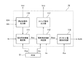
第2実施形態の第3相対オフセット量推定部73は、図13に示すように、パルス指令出力部115と、電気角初期値推定部111と、電気角初期値補正部112と、第2磁気飽和指令出力部116と、オフセット量推定処理部114とを備えている。
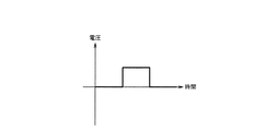
パルス指令出力部115は、システム再起動後の初期診断において異常検出信号SArが異常ありを示す値となったときに、3相電動モータ22のロータ22Rが回転せずかつステータ22Sに磁気飽和が生じない程度のパルス波の電圧指令の出力指令である第2電圧出力指令Voi2を制御演算装置31に出力する。
(Third relative offset amount estimation unit 73)
As shown in FIG. 13, the third relative offset
The pulse
第2実施形態の制御演算装置31は、第2電圧出力指令Voi2の入力に応じてパルス波電圧による通電を行う電圧指令を生成し、生成した電圧指令をゲート駆動回路41A及び41Bに出力する。これにより、第1及び第2のインバータ回路42A及び42Bを介して、例えば、図14に示すパルス波電圧による3相電動モータ22への通電が行われる。
The control
第2実施形態の電気角初期値推定部111は、パルス波電圧の印加に応じて3相電動モータ22に流れる電流の電流検出値Imを電流検出回路34A及び34Bを介して取得し、取得した電流検出値Imのピーク値である第3電流ピーク値Imp3を検出する。
ここで、上記第1実施形態の高調波電圧と同様にパルス波電圧の印加に応じて3相電動モータ22にはモータ電気角θmに依存した電流が流れる。具体的に、この電流のピーク値である第3電流ピーク値Imp3はモータ電気角の情報を有している。
The electrical angle initial
Here, similarly to the harmonic voltage of the first embodiment, a current depending on the motor electrical angle θm flows through the three-phase
そこで、第2実施形態では、上記第1実施形態と同様に、第3電流ピーク値Im3とモータ電気角情報θmiとの関係を予め電気角情報マップとして用意し、この電気角情報マップをROM51に記憶している。
電気角初期値推定部111は、検出した第3電流ピーク値Imp3からROM51に記憶された電気角情報マップを参照してモータ電気角情報θmiを読み出し、読み出したモータ電気角情報θmiに基づきモータ電気角初期値θmsを推定する。そして、推定したモータ電気角初期値θmsを電気角初期値補正部112に出力する。
Therefore, in the second embodiment, as in the first embodiment, the relationship between the third current peak value Im3 and the motor electrical angle information θmi is prepared in advance as an electrical angle information map, and this electrical angle information map is stored in the
The electrical angle initial
第2実施形態の電気角初期値補正部112は、モータ電気角初期値θmsの入力に応じて、3相電動モータ22のロータ22Rが回転せずかつステータ22Sに磁気飽和が生じるほど大きいパルス波の電圧指令(以下、「第2磁気飽和電圧指令」と記載する場合がある)の出力指示を第2磁気飽和指令出力部116に出力する。
第2磁気飽和指令出力部116は、電気角初期値補正部112からの出力指示に応じて、第2磁気飽和電圧指令の出力指令である第2飽和電圧出力指令Vsi2を制御演算装置31に出力する。
The electrical angle initial
The second magnetic saturation
第2実施形態の制御演算装置31は、第2飽和電圧出力指令Vsi2の入力に応じて第2磁気飽和電圧指令を生成し、生成した第2磁気飽和電圧指令をゲート駆動回路41A及び41Bに出力する。これにより、第1及び第2のインバータ回路42A及び42Bを介して、3相電動モータ22への磁気飽和が生じるほど大きいパルス波電圧(以下、「第2磁気飽和電圧」と記載する場合がある)による通電が行われる。
The control
電気角初期値補正部112は、第2磁気飽和電圧の印加に応じて3相電動モータ22に流れる電流の電流検出値Imを電流検出回路34A及び34Bを介して取得し、取得した電流検出値Imのピーク値である第4電流ピーク値Imp4を検出する。
ここで、第2磁気飽和電圧を印加した場合も3相電動モータ22にモータ電気角θmに依存した電流が流れる。即ち、上記第1実施形態の第1磁気飽和電圧を印加した場合と同様の特性を有する電流が流れる。
The electrical angle initial
Here, even when the second magnetic saturation voltage is applied, a current depending on the motor electrical angle θm flows through the three-phase
そこで、第2実施形態では、第4電流ピーク値Im4とモータ電気角補正情報Cmとの関係を予め補正情報マップとして用意し、この補正情報マップをROM51に記憶している。
電気角初期値補正部112は、検出した第4電流ピーク値Imp4からROM51に記憶された補正情報マップを参照してモータ電気角補正情報Cmを読み出し、読み出したモータ電気角補正情報Cmに基づきモータ電気角初期値θmsを補正する。そして、補正後のモータ電気角初期値θmscをオフセット量推定処理部114に出力する。
Therefore, in the second embodiment, the relationship between the fourth current peak value Im4 and the motor electrical angle correction information Cm is prepared in advance as a correction information map, and this correction information map is stored in the
The electrical angle initial
オフセット量推定処理部114は、電気角初期値補正部112からの補正後のモータ電気角初期値θmscに基づきモータ電気角原点θmdを推定し、このモータ電気角原点θmdと、システム再起動時の出力軸回転角検出値の基準値θosrとに基づき第2の相対オフセット量θoff2を推定する。そして、推定した第2の相対オフセット量θoff2をRAM50に記憶する。
The offset amount
ここで、電気角初期値推定部111がモータ電気角初期値推定部に対応し、モータ電気角推定部63がモータ電気角推定部に対応し、制御演算装置31及びモータ電気角検出回路23がモータ駆動制御部に対応する。
また、操舵トルクセンサ13がトルク検出部に対応し、出力側回転角センサ13cがステアリング舵角検出部に対応し、3相電動モータ22が多相電動モータに対応し、レゾルバ23a及び角度演算部60がモータ電気角検出部に対応する。
また、第1及び第2のインバータ回路42A及び42Bがモータ駆動回路に対応し、制御演算装置31が制御演算装置に対応し、レゾルバ異常診断部61が、異常診断部に対応する。
Here, the electrical angle initial
Further, the
The first and
(第2実施形態の効果)
第2実施形態は、上記第1実施形態の効果に加えて以下の効果を奏する。
(1)第2実施形態に係るモータ制御装置25は、電気角初期値推定部111が、3相電動モータ22へのパルス波の通電を行った際の電流応答に基づきモータ電気角初期値θmsを推定する。
(Effect of 2nd Embodiment)
The second embodiment has the following effects in addition to the effects of the first embodiment.
(1) In the
この構成であれば、3相電動モータ22への高調波の通電に応じた3相電動モータ22のモータ電気角に依存した電流応答に基づきモータ電気角初期値θmsを推定することが可能となる。例えば、応答電流のピーク値等から得られるモータ電気角の情報に基づきモータ電気角初期値θmsを推定することが可能となる。
これにより、システムが再起動後の初期診断で、レゾルバ23a及び角度演算部60の少なくとも一方が異常と診断されても、3相電動モータ22を正常時と遜色なく転流制御可能なモータ電気角を推定することが可能となる。
With this configuration, it is possible to estimate the motor electrical angle initial value θms based on the current response depending on the motor electrical angle of the three-phase
As a result, even if at least one of the
(2)電第2実施形態に係るモータ制御装置25は、電気角初期値補正部112が、3相電動モータ22に対して磁気飽和が発生する程度のパルス波の通電を行った際の電流応答に基づきモータ電気角初期値θmsを補正する。
この構成であれば、3相電動モータ22への磁気飽和が発生する程度の高調波の通電に応じた3相電動モータ22のモータ電気角に依存した電流応答に基づきモータ電気角初期値θmsを補正することが可能となる。例えば、応答電流のピーク値等から得られる情報に基づきモータ電気角初期値θmsを補正することが可能となる。
これにより、より正確なモータ電気角初期値θmsを得ることが可能となる。
(2) Electricity In the
With this configuration, the motor electrical angle initial value θms is determined based on the current response depending on the motor electrical angle of the three-phase
As a result, a more accurate motor electrical angle initial value θms can be obtained.
(第3実施形態)
次に、本発明の第3実施形態を説明する。
(構成)
この第3実施形態は、上記第1実施形態の相対オフセット量推定部62における第2相対オフセット量推定部71に代えて第4相対オフセット量推定部74を備える点で相違し、それ以外は上記第1実施形態と同様となる。
以下、上記第1実施形態と同じ構成部については同じ符号を付して適宜説明を省略し、異なる部分を詳細に説明する。
(Third embodiment)
Next, a third embodiment of the present invention will be described.
(Constitution)
The third embodiment is different in that a fourth relative offset
Hereinafter, the same components as those in the first embodiment are denoted by the same reference numerals, description thereof will be omitted as appropriate, and different portions will be described in detail.
(第4相対オフセット量推定部74)
第3実施形態の第4相対オフセット量推定部74は、図15に示すように、高調波指令出力部110と、電気角初期値推定部111と、電気角初期値補正部112と、ステップ指令出力部117と、オフセット量推定処理部114とを備えている。
第3実施形態の電気角初期値補正部112は、モータ電気角初期値θmsの入力に応じて、3相電動モータ22のロータ22Rが回転しない程度のステップ波の電圧指令(以下、「ステップ電圧指令」と記載する場合がある)の出力指示をステップ指令出力部117に出力する。
(Fourth relative offset amount estimation unit 74)
As shown in FIG. 15, the fourth relative offset
The electrical angle initial
ステップ指令出力部117は、電気角初期値補正部112からの出力指示に応じて、ステップ電圧指令の出力指令であるステップ電圧出力指令Vsi3を制御演算装置31に出力する。
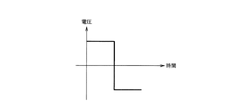
第3実施形態の制御演算装置31は、ステップ電圧出力指令Vsi3の入力に応じてステップ電圧指令を生成し、生成したステップ電圧指令をゲート駆動回路41A及び41Bに出力する。これにより、第1及び第2のインバータ回路42A及び42Bを介して、3相電動モータ22へのステップ波電圧(以下、「ステップ波電圧」と記載する場合がある)による通電が行われる。
The step
The control
電気角初期値補正部112は、例えば、図16に示すようなステップ波電圧の印加に応じて3相電動モータ22に流れる電流の電流検出値Imを電流検出回路34A及び34Bを介して取得し、取得した電流検出値Imのピーク値である第5電流ピーク値Imp5を検出する。
ここで、ステップ波電圧を印加した場合も3相電動モータ22にモータ電気角θmに依存した電流が流れる。そこで、第2実施形態では、第5電流ピーク値Im5とモータ電気角補正情報Cmとの関係を予め補正情報マップとして用意し、この補正情報マップをROM51に記憶している。
For example, the electrical angle initial
Here, even when a step wave voltage is applied, a current depending on the motor electrical angle θm flows through the three-phase
電気角初期値補正部112は、検出した第5電流ピーク値Imp5からROM51に記憶された補正情報マップを参照してモータ電気角補正情報Cmを読み出し、読み出したモータ電気角補正情報Cmに基づきモータ電気角初期値θmsを補正する。そして、補正後のモータ電気角初期値θmscをオフセット量推定処理部114に出力する。
オフセット量推定処理部114は、電気角初期値補正部112からの補正後のモータ電気角初期値θmscに基づきモータ電気角原点θmdを推定する。さらに、このモータ電気角原点θmdと、システム再起動時の出力軸回転角検出値の基準値θosrとに基づき第2の相対オフセット量θoff2を推定する。そして、推定した第2の相対オフセット量θoff2をRAM50に記憶する。
The electrical angle initial
The offset amount
ここで、電気角初期値推定部111がモータ電気角初期値推定部に対応し、モータ電気角推定部63がモータ電気角推定部に対応し、制御演算装置31及びモータ電気角検出回路23がモータ駆動制御部に対応する。
また、操舵トルクセンサ13がトルク検出部に対応し、出力側回転角センサ13cがステアリング舵角検出部に対応し、3相電動モータ22が多相電動モータに対応し、レゾルバ23a及び角度演算部60がモータ電気角検出部に対応する。
また、第1及び第2のインバータ回路42A及び42Bがモータ駆動回路に対応し、制御演算装置31が制御演算装置に対応し、レゾルバ異常診断部61が、異常診断部に対応する。
Here, the electrical angle initial
Further, the
The first and
(第3実施形態の効果)
第3実施形態は、上記第1及び第2実施形態の効果に加えて以下の効果を奏する。
(1)第3実施形態に係るモータ制御装置25は、3相電動モータ22に対してステップ状波の通電を行った際の電流応答に基づきモータ電気角初期値θmsを補正する。
この構成であれば、3相電動モータ22へのステップ状波の通電に応じた3相電動モータ22のモータ電気角に依存した電流応答に基づきモータ電気角初期値θmsを補正することが可能となる。例えば、応答電流のピーク値等から得られる情報に基づきモータ電気角初期値θmsを補正することが可能となる。
これにより、より正確なモータ電気角初期値θmsを得ることが可能となる。
(Effect of the third embodiment)
The third embodiment has the following effects in addition to the effects of the first and second embodiments.
(1) The
With this configuration, it is possible to correct the motor electrical angle initial value θms based on the current response depending on the motor electrical angle of the three-phase
As a result, a more accurate motor electrical angle initial value θms can be obtained.
(変形例)
(1)上記実施形態においては、操舵トルクセンサ13を構成する出力側回転角センサ13cで検出した出力軸回転角検出値θosに基づきモータ電気角を推定する構成としたが、この構成に限らない。例えば、入力側回転角センサ13bで検出した入力軸回転角θisに基づきモータ電気角を推定するなど、ステアリングホイール11の操作に伴って回転する軸の回転角を検出するセンサであれば他のセンサで検出した回転角に基づきモータ電気角を推定してもよい。
(Modification)
(1) In the above embodiment, the motor electrical angle is estimated based on the detected output shaft rotation angle value θos detected by the output-side
(2)上記実施形態においては、制御演算装置31の操舵補助制御処理で、操舵補助電流指令値に基づいてd軸電流指令値Id*及びq軸電流指令値Iq*を算出し、これらをdq相−3相変換してU相電流指令値Iu*、V相電流指令値Iv*及びW相電流指令値Iw*を算出し、これらと電流検出値の相毎の加算値との電流偏差ΔIu、ΔIv及びΔIwを算出する場合について説明した。しかしながら、本発明は上記構成に限定されるものではなく、電流検出値の相毎の加算値をdq軸変換し、これらとd軸電流指令値Id*及びq軸電流指令値Iq*との偏差ΔId及びΔIqを算出し、偏差ΔId及びΔIqをdq相−3相変換するようにしてもよい。
(2) In the above embodiment, in the steering assist control process of the control
(3)上記実施形態においては、本発明をコラムアシスト式の電動パワーステアリング装置に適用した例を説明したが、この構成に限らず、例えば、ラックアシスト式又はピニオンアシスト式の電動パワーステアリング装置に適用する構成としてもよい。 (3) In the above embodiment, an example in which the present invention is applied to a column assist type electric power steering apparatus has been described. However, the present invention is not limited to this configuration. For example, the present invention is applied to a rack assist type or pinion assist type electric power steering apparatus. It is good also as composition to apply.
1…車両、3…電動パワーステアリング装置、11…ステアリングホイール、12…ステアリングシャフト、12b…出力軸、13…操舵トルクセンサ、13c…出力側回転角センサ、18…ステアリングギヤ、20…操舵補助機構、22…3相電動モータ、23…モータ電気角検出回路、23a…レゾルバ、23b…メインモータ電気角検出回路、23c…サブモータ電気角検出回路、23d…電気角選択部、25…モータ制御装置、26…車速センサ、27…バッテリー、28…IGNスイッチ、31…制御演算装置、32A…第1のモータ駆動回路、32B…第2のモータ駆動回路、33A…第1のモータ電流遮断回路、33B…第2のモータ電流遮断回路、34A,34B…電流検出回路、35A…第1の異常検出回路、35B…第2の異常検出回路、41A,41B…ゲート駆動回路、42A…第1のインバータ回路、42B…第2のインバータ回路、43…ノイズフィルタ、44A…第1の電源遮断回路、44B…第2の電源遮断回路、60…角度演算部、61…レゾルバ異常診断部、62…相対オフセット量推定部、63…モータ電気角推定部、70…第1相対オフセット量推定部、71,73,74…第2,第3,第4相対オフセット量推定部、72…相対オフセット量選択部、110…高調波指令出力部、111…電気角初期値推定部、112…電気角初期値補正部、113,116…第1,第2磁気飽和指令出力部、114…オフセット量推定処理部、115…パルス指令出力部、117…ステップ指令出力部
DESCRIPTION OF SYMBOLS 1 ... Vehicle, 3 ... Electric power steering apparatus, 11 ... Steering wheel, 12 ... Steering shaft, 12b ... Output shaft, 13 ... Steering torque sensor, 13c ... Output side rotation angle sensor, 18 ... Steering gear, 20 ... Steering assist
Claims (8)
ステアリングの舵角を検出するステアリング舵角検出部で検出した舵角と前記モータ電気角初期値推定部で推定した前記初期値とに基づき前記モータ電気角を推定するモータ電気角推定部と、
前記モータ電気角検出部が正常時は前記モータ電気角検出部で検出したモータ電気角に基づき前記多相電動モータを駆動制御し、前記システム再起動後の初期診断で前記モータ電気角検出部が異常と診断時は前記モータ電気角推定部で推定したモータ電気角推定値に基づき前記多相電動モータを駆動制御するモータ駆動制御部と、を備えるモータ制御装置。 In the initial diagnosis after system restart, if the motor electrical angle detector that detects the motor electrical angle of the multiphase electric motor that generates the steering assist force is diagnosed as abnormal, the motor drive signal to the multiphase electric motor is A motor electrical angle initial value estimator that estimates an initial value of the motor electrical angle based on a response output of the multiphase electric motor according to an input;
A motor electrical angle estimator that estimates the motor electrical angle based on the steering angle detected by the steering angle detector that detects the steering angle of the steering and the initial value estimated by the initial value of the motor electrical angle;
When the motor electrical angle detection unit is normal, the multiphase electric motor is driven and controlled based on the motor electrical angle detected by the motor electrical angle detection unit, and the motor electrical angle detection unit performs initial diagnosis after the system restarts. A motor control device comprising: a motor drive control unit that drives and controls the multiphase electric motor based on a motor electrical angle estimation value estimated by the motor electrical angle estimation unit when an abnormality is diagnosed.
ステアリングの舵角を検出するステアリング舵角検出部と、
操舵補助力を発生する多相電動モータと、
前記多相電動モータのモータ電気角を検出するモータ電気角検出部と、
前記多相電動モータに駆動電流を供給するモータ駆動回路と、
前記トルク検出部で検出したトルクと前記モータ電気角検出部で検出したモータ電気角とに基づき前記モータ駆動回路を駆動制御する制御演算装置と、
前記モータ電気角検出部の異常を診断する異常診断部と、
システム再起動後の前記異常診断部による初期診断において、前記モータ電気角検出部が異常と診断されると、前記多相電動モータへのモータ駆動信号の入力に応じた前記多相電動モータの応答出力に基づき前記モータ電気角の初期値を推定するモータ電気角初期値推定部と、
前記ステアリング舵角検出部で検出した舵角と前記モータ電気角初期値推定部で推定したモータ電気角初期値とに基づき前記モータ電気角を推定するモータ電気角推定部と、を備え、
前記制御演算装置は、システム再起動後の前記異常診断部による初期診断で前記モータ電気角検出部が異常と診断されると、前記トルク検出部で検出したトルクと前記モータ電気角推定部で推定したモータ電気角推定値とに基づき前記モータ駆動回路を駆動制御するモータ制御装置。 A torque detector for detecting torque transmitted to the steering mechanism;
A steering angle detector that detects the steering angle of the steering;
A multiphase electric motor that generates steering assist force;
A motor electrical angle detector for detecting a motor electrical angle of the multiphase electric motor;
A motor drive circuit for supplying a drive current to the multiphase electric motor;
A control arithmetic device that drives and controls the motor drive circuit based on the torque detected by the torque detector and the motor electrical angle detected by the motor electrical angle detector;
An abnormality diagnosis unit for diagnosing an abnormality in the motor electrical angle detection unit;
In the initial diagnosis by the abnormality diagnosis unit after system restart, if the motor electrical angle detection unit is diagnosed as abnormal, the response of the multiphase electric motor according to the input of the motor drive signal to the multiphase electric motor A motor electrical angle initial value estimating unit that estimates an initial value of the motor electrical angle based on an output;
A motor electrical angle estimation unit that estimates the motor electrical angle based on the steering angle detected by the steering angle detection unit and the motor electrical angle initial value estimated by the motor electrical angle initial value estimation unit;
When the motor electrical angle detection unit is diagnosed as abnormal in the initial diagnosis by the abnormality diagnosis unit after system restart, the control arithmetic unit estimates the torque detected by the torque detection unit and the motor electrical angle estimation unit. A motor control device that controls the drive of the motor drive circuit based on the estimated motor electrical angle.
Priority Applications (5)
| Application Number | Priority Date | Filing Date | Title |
|---|---|---|---|
| JP2015159584A JP6156458B2 (en) | 2015-08-12 | 2015-08-12 | Motor control device, electric power steering device, and vehicle |
| US15/542,767 US10293851B2 (en) | 2015-08-12 | 2016-07-25 | Motor control device, electric power steering device, and vehicle |
| CN201680046676.1A CN107949985A (en) | 2015-08-12 | 2016-07-25 | Controller for motor, electric power-assisted steering apparatus and vehicle |
| PCT/JP2016/071748 WO2017026262A1 (en) | 2015-08-12 | 2016-07-25 | Motor control device, electric power steering device, and vehicle |
| EP16834959.5A EP3232563B1 (en) | 2015-08-12 | 2016-07-25 | Motor control device, electric power steering device, and vehicle |
Applications Claiming Priority (1)
| Application Number | Priority Date | Filing Date | Title |
|---|---|---|---|
| JP2015159584A JP6156458B2 (en) | 2015-08-12 | 2015-08-12 | Motor control device, electric power steering device, and vehicle |
Publications (3)
| Publication Number | Publication Date |
|---|---|
| JP2017038498A JP2017038498A (en) | 2017-02-16 |
| JP2017038498A5 JP2017038498A5 (en) | 2017-03-23 |
| JP6156458B2 true JP6156458B2 (en) | 2017-07-05 |
Family
ID=57983207
Family Applications (1)
| Application Number | Title | Priority Date | Filing Date |
|---|---|---|---|
| JP2015159584A Active JP6156458B2 (en) | 2015-08-12 | 2015-08-12 | Motor control device, electric power steering device, and vehicle |
Country Status (5)
| Country | Link |
|---|---|
| US (1) | US10293851B2 (en) |
| EP (1) | EP3232563B1 (en) |
| JP (1) | JP6156458B2 (en) |
| CN (1) | CN107949985A (en) |
| WO (1) | WO2017026262A1 (en) |
Families Citing this family (11)
| Publication number | Priority date | Publication date | Assignee | Title |
|---|---|---|---|---|
| CN109831921B (en) * | 2016-09-20 | 2021-08-20 | 日立安斯泰莫株式会社 | sensor device |
| US11152885B2 (en) * | 2016-11-18 | 2021-10-19 | Mitsubishi Electric Corporation | Abnormality detection apparatus |
| JP6922669B2 (en) * | 2017-11-07 | 2021-08-18 | 株式会社ジェイテクト | Steering control device |
| FR3080919B1 (en) * | 2018-05-07 | 2020-11-20 | Continental Automotive France | METHOD FOR DETERMINING AN ESTIMATED CURRENT OF A THREE-PHASE ELECTRIC MOTOR IN DEGRADE MODE |
| US10965233B2 (en) * | 2018-05-11 | 2021-03-30 | Nsk Ltd. | Motor control device and electric power steering device including the same |
| JP7003863B2 (en) * | 2018-07-20 | 2022-02-04 | トヨタ自動車株式会社 | Vehicle controls, control methods and control programs |
| WO2020080170A1 (en) * | 2018-10-15 | 2020-04-23 | 日本電産株式会社 | Failure diagnosis method, power conversion device, motor module, and electric power steering device |
| FR3088717B1 (en) * | 2018-11-15 | 2021-09-17 | Electricfil Automotive | DETECTION SYSTEM FOR STEERING OF A VEHICLE ALLOWING THE MEASUREMENT OF TORQUE AND ABSOLUTE MULTI-TURN STEERING ANGLE |
| JP7234737B2 (en) * | 2019-03-28 | 2023-03-08 | 株式会社デンソー | detection unit |
| JP7280099B2 (en) * | 2019-04-19 | 2023-05-23 | 株式会社ジェイテクト | Motor control system and motor control device |
| JP7550098B2 (en) * | 2021-04-06 | 2024-09-12 | 株式会社デンソー | MOTOR CONTROL DEVICE AND STEERING SYSTEM INCLUDING THE SAME |
Family Cites Families (17)
| Publication number | Priority date | Publication date | Assignee | Title |
|---|---|---|---|---|
| JP2000217386A (en) * | 1998-11-19 | 2000-08-04 | Matsushita Electric Ind Co Ltd | Position sensorless motor controller |
| JP3805336B2 (en) | 2003-10-22 | 2006-08-02 | ファナック株式会社 | Magnetic pole position detection apparatus and method |
| KR100572397B1 (en) * | 2004-11-16 | 2006-04-18 | 현대모비스 주식회사 | Fault diagnosis system of torque sensor for steering device of vehicle and its method |
| JP2007269277A (en) * | 2006-03-31 | 2007-10-18 | Isuzu Motors Ltd | Electric power steering device |
| JP4329792B2 (en) | 2006-08-10 | 2009-09-09 | トヨタ自動車株式会社 | Electric power steering device |
| WO2009145270A1 (en) * | 2008-05-28 | 2009-12-03 | 本田技研工業株式会社 | Motor control device, and electric steering device |
| JP2010029030A (en) * | 2008-07-23 | 2010-02-04 | Jtekt Corp | Motor controller |
| JP5263090B2 (en) * | 2009-09-04 | 2013-08-14 | トヨタ自動車株式会社 | Electric power steering device |
| JP4998836B2 (en) | 2009-09-30 | 2012-08-15 | 株式会社デンソー | Control device for multi-phase rotating machine and electric power steering device using the same |
| JP5126325B2 (en) * | 2009-10-09 | 2013-01-23 | 株式会社デンソー | Rotation angle detection device and electric power steering device using the same |
| JP5699527B2 (en) * | 2010-10-21 | 2015-04-15 | 株式会社ジェイテクト | Electric power steering device |
| US9385648B2 (en) | 2010-10-04 | 2016-07-05 | Jtekt Corporation | Electric power steering apparatus |
| DE102013013623B4 (en) * | 2012-08-29 | 2022-06-30 | Kanzaki Kokyukoki Mfg. Co., Ltd. | Motor control system for an electric motor driven vehicle |
| JP5661839B2 (en) * | 2013-03-14 | 2015-01-28 | ファナック株式会社 | Synchronous motor control system with abnormality detection diagnosis function |
| US9073569B2 (en) * | 2013-03-19 | 2015-07-07 | Mitsubishi Electric Research Laboratories, Inc. | Determining steering angle of steering column of vehicle |
| JP5569626B1 (en) * | 2013-06-17 | 2014-08-13 | 日本精工株式会社 | Motor control device, electric power steering device using the same, and vehicle |
| CN104584423B (en) * | 2013-08-12 | 2017-06-13 | 日本精工株式会社 | Motor control device, electric power steering device using same, and vehicle |
-
2015
- 2015-08-12 JP JP2015159584A patent/JP6156458B2/en active Active
-
2016
- 2016-07-25 US US15/542,767 patent/US10293851B2/en active Active
- 2016-07-25 WO PCT/JP2016/071748 patent/WO2017026262A1/en not_active Ceased
- 2016-07-25 EP EP16834959.5A patent/EP3232563B1/en not_active Not-in-force
- 2016-07-25 CN CN201680046676.1A patent/CN107949985A/en active Pending
Also Published As
| Publication number | Publication date |
|---|---|
| WO2017026262A1 (en) | 2017-02-16 |
| EP3232563B1 (en) | 2019-07-24 |
| US10293851B2 (en) | 2019-05-21 |
| EP3232563A1 (en) | 2017-10-18 |
| CN107949985A (en) | 2018-04-20 |
| EP3232563A4 (en) | 2018-04-25 |
| US20170369094A1 (en) | 2017-12-28 |
| JP2017038498A (en) | 2017-02-16 |
Similar Documents
| Publication | Publication Date | Title |
|---|---|---|
| JP6156458B2 (en) | Motor control device, electric power steering device, and vehicle | |
| JP5907314B2 (en) | Motor control device, electric power steering device using the same, and vehicle | |
| JP6004025B2 (en) | Motor control device, electric power steering device using the same, and vehicle | |
| JP5569626B1 (en) | Motor control device, electric power steering device using the same, and vehicle | |
| EP3243728B1 (en) | Motor control device, electric power steering device, and vehicle | |
| JP6583592B1 (en) | Motor control device and electric power steering device provided with the same | |
| CN104205616A (en) | Motor control device, electric power steering device using same, and vehicle | |
| CN104170242A (en) | Motor control device, electric power steering device using same, and vehicle | |
| WO2009123107A1 (en) | Motor control device and electric power steering device | |
| JP5263079B2 (en) | Electric power steering device | |
| JP6183424B2 (en) | Motor control device, electric power steering device, and vehicle | |
| JP2016096608A (en) | Motor control device, electric power steering device using the same, and vehicle | |
| JP6119809B2 (en) | Motor control device, electric power steering device, and vehicle | |
| JP2011230531A (en) | Device for controlling motor | |
| JP2017036001A5 (en) | ||
| JP6641908B2 (en) | Motor control device, motor control method, motor control program, electric motor, electric power steering device, and vehicle |
Legal Events
| Date | Code | Title | Description |
|---|---|---|---|
| A521 | Request for written amendment filed |
Free format text: JAPANESE INTERMEDIATE CODE: A523 Effective date: 20170209 |
|
| A621 | Written request for application examination |
Free format text: JAPANESE INTERMEDIATE CODE: A621 Effective date: 20170209 |
|
| A871 | Explanation of circumstances concerning accelerated examination |
Free format text: JAPANESE INTERMEDIATE CODE: A871 Effective date: 20170209 |
|
| A975 | Report on accelerated examination |
Free format text: JAPANESE INTERMEDIATE CODE: A971005 Effective date: 20170420 |
|
| TRDD | Decision of grant or rejection written | ||
| A01 | Written decision to grant a patent or to grant a registration (utility model) |
Free format text: JAPANESE INTERMEDIATE CODE: A01 Effective date: 20170509 |
|
| A61 | First payment of annual fees (during grant procedure) |
Free format text: JAPANESE INTERMEDIATE CODE: A61 Effective date: 20170522 |
|
| R150 | Certificate of patent or registration of utility model |
Ref document number: 6156458 Country of ref document: JP Free format text: JAPANESE INTERMEDIATE CODE: R150 |
|
| R250 | Receipt of annual fees |
Free format text: JAPANESE INTERMEDIATE CODE: R250 |
|
| R250 | Receipt of annual fees |
Free format text: JAPANESE INTERMEDIATE CODE: R250 |