JP6155213B2 - Saddle riding vehicle - Google Patents
Saddle riding vehicle Download PDFInfo
- Publication number
- JP6155213B2 JP6155213B2 JP2014059069A JP2014059069A JP6155213B2 JP 6155213 B2 JP6155213 B2 JP 6155213B2 JP 2014059069 A JP2014059069 A JP 2014059069A JP 2014059069 A JP2014059069 A JP 2014059069A JP 6155213 B2 JP6155213 B2 JP 6155213B2
- Authority
- JP
- Japan
- Prior art keywords
- vehicle
- throttle
- engine
- throttle motor
- chain tensioner
- Prior art date
- Legal status (The legal status is an assumption and is not a legal conclusion. Google has not performed a legal analysis and makes no representation as to the accuracy of the status listed.)
- Active
Links
- 230000007246 mechanism Effects 0.000 claims description 15
- 230000009467 reduction Effects 0.000 claims description 11
- 230000005540 biological transmission Effects 0.000 description 5
- 239000000446 fuel Substances 0.000 description 4
- 125000002066 L-histidyl group Chemical group [H]N1C([H])=NC(C([H])([H])[C@](C(=O)[*])([H])N([H])[H])=C1[H] 0.000 description 2
- 238000010586 diagram Methods 0.000 description 2
- 238000002347 injection Methods 0.000 description 2
- 239000007924 injection Substances 0.000 description 2
- 230000008901 benefit Effects 0.000 description 1
- 230000008859 change Effects 0.000 description 1
- 238000002485 combustion reaction Methods 0.000 description 1
- 239000002826 coolant Substances 0.000 description 1
- 238000001816 cooling Methods 0.000 description 1
- 238000001514 detection method Methods 0.000 description 1
- 238000007599 discharging Methods 0.000 description 1
- 238000011038 discontinuous diafiltration by volume reduction Methods 0.000 description 1
- 238000006073 displacement reaction Methods 0.000 description 1
- 230000004044 response Effects 0.000 description 1
- 230000000630 rising effect Effects 0.000 description 1
- 238000000926 separation method Methods 0.000 description 1
- 238000009423 ventilation Methods 0.000 description 1
Images


Classifications
-
- F—MECHANICAL ENGINEERING; LIGHTING; HEATING; WEAPONS; BLASTING
- F02—COMBUSTION ENGINES; HOT-GAS OR COMBUSTION-PRODUCT ENGINE PLANTS
- F02D—CONTROLLING COMBUSTION ENGINES
- F02D11/00—Arrangements for, or adaptations to, non-automatic engine control initiation means, e.g. operator initiated
- F02D11/06—Arrangements for, or adaptations to, non-automatic engine control initiation means, e.g. operator initiated characterised by non-mechanical control linkages, e.g. fluid control linkages or by control linkages with power drive or assistance
- F02D11/10—Arrangements for, or adaptations to, non-automatic engine control initiation means, e.g. operator initiated characterised by non-mechanical control linkages, e.g. fluid control linkages or by control linkages with power drive or assistance of the electric type
-
- F—MECHANICAL ENGINEERING; LIGHTING; HEATING; WEAPONS; BLASTING
- F01—MACHINES OR ENGINES IN GENERAL; ENGINE PLANTS IN GENERAL; STEAM ENGINES
- F01L—CYCLICALLY OPERATING VALVES FOR MACHINES OR ENGINES
- F01L1/00—Valve-gear or valve arrangements, e.g. lift-valve gear
- F01L1/02—Valve drive
- F01L1/022—Chain drive
-
- F—MECHANICAL ENGINEERING; LIGHTING; HEATING; WEAPONS; BLASTING
- F02—COMBUSTION ENGINES; HOT-GAS OR COMBUSTION-PRODUCT ENGINE PLANTS
- F02M—SUPPLYING COMBUSTION ENGINES IN GENERAL WITH COMBUSTIBLE MIXTURES OR CONSTITUENTS THEREOF
- F02M35/00—Combustion-air cleaners, air intakes, intake silencers, or induction systems specially adapted for, or arranged on, internal-combustion engines
- F02M35/16—Combustion-air cleaners, air intakes, intake silencers, or induction systems specially adapted for, or arranged on, internal-combustion engines characterised by use in vehicles
- F02M35/162—Motorcycles; All-terrain vehicles, e.g. quads, snowmobiles; Small vehicles, e.g. forklifts
-
- B—PERFORMING OPERATIONS; TRANSPORTING
- B62—LAND VEHICLES FOR TRAVELLING OTHERWISE THAN ON RAILS
- B62K—CYCLES; CYCLE FRAMES; CYCLE STEERING DEVICES; RIDER-OPERATED TERMINAL CONTROLS SPECIALLY ADAPTED FOR CYCLES; CYCLE AXLE SUSPENSIONS; CYCLE SIDE-CARS, FORECARS, OR THE LIKE
- B62K2202/00—Motorised scooters
-
- F—MECHANICAL ENGINEERING; LIGHTING; HEATING; WEAPONS; BLASTING
- F02—COMBUSTION ENGINES; HOT-GAS OR COMBUSTION-PRODUCT ENGINE PLANTS
- F02B—INTERNAL-COMBUSTION PISTON ENGINES; COMBUSTION ENGINES IN GENERAL
- F02B61/00—Adaptations of engines for driving vehicles or for driving propellers; Combinations of engines with gearing
- F02B61/02—Adaptations of engines for driving vehicles or for driving propellers; Combinations of engines with gearing for driving cycles
Description
この発明は、スロットル弁の開度をスロットルモータによって制御する鞍乗型車両に関するものである。 The present invention relates to a straddle-type vehicle in which the opening of a throttle valve is controlled by a throttle motor.
スクータ型車両等の鞍乗型車両において、スロットルグリップ等の操作子の操作量をセンサによって検出し、その検出値に基づいてスロットル弁の開度を制御するものが実用化されている。この場合、スロットル弁には減速機構を介してスロットルモータが接続されており、スロットルモータが前記センサの検出信号を基にして制御装置によって制御される。 In a saddle riding type vehicle such as a scooter type vehicle, a sensor that detects an operation amount of an operator such as a throttle grip by a sensor and controls an opening of a throttle valve based on the detected value has been put into practical use. In this case, a throttle motor is connected to the throttle valve via a speed reduction mechanism, and the throttle motor is controlled by the control device based on the detection signal of the sensor.
ところで、スクータ型車両等の鞍乗型車両においては、エンジンがシートの下方において車体フレームに上下揺動可能に支持され、エンジンのシリンダ部がクランクケースから車体前方側に延出するとともに、シリンダ部の上面側に吸気通路が接続される構造が採用されることがある。この場合、エンジンのシリンダ部の上面に沿って配管される吸気通路の途中にはスロットル弁が配置され、そのスロットル弁に近接してスロットルモータが配置されることになる。このため、エンジンの周囲の機能部品、例えば、収納ボックス等のレイアウトがスロットルモータによって制約され易くなる。このため、これに対処する鞍乗型車両が案出されている(例えば、特許文献1参照)。 By the way, in a straddle-type vehicle such as a scooter type vehicle, the engine is supported by the vehicle body frame so as to be vertically swingable below the seat, and the cylinder portion of the engine extends from the crankcase to the vehicle body front side. In some cases, a structure in which an intake passage is connected to the upper surface side of the housing. In this case, a throttle valve is arranged in the middle of the intake passage piped along the upper surface of the cylinder portion of the engine, and a throttle motor is arranged in the vicinity of the throttle valve. For this reason, the layout of functional parts around the engine, such as a storage box, is likely to be restricted by the throttle motor. For this reason, a straddle-type vehicle has been devised to deal with this (for example, see Patent Document 1).
特許文献1に記載の鞍乗型車両は、吸気通路の前端部が下方に湾曲してシリンダ部の上面に接続され、スロットルモータが、車両の平面視で一部が吸気通路と重なり、かつ車両の側面視において、シリンダ部の上面と吸気通路との間に挟まれる位置に配置されている。これにより、シリンダ部の上面と吸気通路との間のデッドスペースを有効活用してスロットルモータが配置され、エンジンの周囲の機能部品のレイアウトが制限を受けにくくなる。 In the saddle riding type vehicle described in Patent Document 1, the front end portion of the intake passage is curved downward and connected to the upper surface of the cylinder portion, and the throttle motor partially overlaps the intake passage in a plan view of the vehicle. In the side view, the cylinder portion is disposed at a position sandwiched between the upper surface of the cylinder portion and the intake passage. As a result, the throttle motor is disposed by effectively utilizing the dead space between the upper surface of the cylinder portion and the intake passage, and the layout of functional components around the engine is less likely to be restricted.
ところで、シリンダ部が車体前方側に延出するようにエンジンが車体フレームに取り付けられる鞍乗型車両においては、エンジン内のタイミングチェーンの張力を調整する部品であるチェーンテンショナの一部がシリンダ部の上面から上方に突出して配置される場合がある。このような場合、上述のようにシリンダ部の上面と吸気通路との間に挟まれる位置にスロットルモータを配置しようとすると、スロットルモータがチェーンテンショナと近接し易くなる。このため、スロットルモータとチェーンテンショナとの近接を回避するために、吸気通路を上方側に配置する必要があり、エンジンの周囲の機能部品のレイアウトが制限されてしまう。 By the way, in a saddle-ride type vehicle in which the engine is attached to the vehicle body frame so that the cylinder portion extends toward the front side of the vehicle body, a part of the chain tensioner that is a component for adjusting the tension of the timing chain in the engine is a part of the cylinder portion. In some cases, the upper surface protrudes upward. In such a case, if the throttle motor is to be disposed at a position sandwiched between the upper surface of the cylinder portion and the intake passage as described above, the throttle motor is likely to be close to the chain tensioner. For this reason, in order to avoid the proximity of the throttle motor and the chain tensioner, it is necessary to arrange the intake passage on the upper side, and the layout of functional components around the engine is limited.
そこでこの発明は、スロットルモータをチェーンテンショナと適切な間隔を維持してエンジンの上方に配置できるようにして、エンジンの周囲の機能部品のレイアウトの自由度を高めることのできる鞍乗型車両を提供しようとするものである。 Accordingly, the present invention provides a straddle-type vehicle capable of increasing the degree of freedom in layout of functional components around the engine by allowing the throttle motor to be disposed above the engine while maintaining an appropriate distance from the chain tensioner. It is something to try.
この発明の一形態の鞍乗型車両は、上記課題を解決するために、シリンダ部(36,37,38)が車体前方に向かって延出するように車体フレーム(11)に取り付けられたエンジン(2)と、前記シリンダ部(36,37,38)の上部後方側から車体前方側に延出して、前端部が下方に湾曲して前記シリンダ部(36,37,38)の吸気口に接続される吸気通路(21,22,23)と、前記吸気通路(21,22,23)に設けられ、前記吸気通路(21,22,23)を流通する吸気量を調整するスロットル弁(24)と、前記スロットル弁(24)を駆動するスロットルモータ(26)と、前記エンジン(2)内のタイミングチェーン(32)の張力を調整する部品であり、その一部が前記シリンダ部(36,37,38)の上面から上方に突出するチェーンテンショナ(33)と、を備え、前記スロットル弁(24)が、車両の平面視において、前記シリンダ部(36,37,38)の上面と重なる位置に配置される鞍乗型車両であって、前記スロットルモータ(26)は、車両の側面視において、前記エンジン(2)の上面と前記吸気通路(21,22,23)との間の位置で、前記スロットルモータ(26)の下端を通る水平線(H1)が前記チェーンテンショナ(33)と重なる位置に配置され、かつ前記スロットルモータ(26)の軸心部(26a)が前記チェーンテンショナ(33)と前後方向にずれるように、かつ車両前後方向でクランクケース(35)の上面から上方に隆起する前壁(35a)と前記チェーンテンショナ(33)との間に、配置されるようにした。 In order to solve the above-described problem, a saddle-ride type vehicle according to one aspect of the present invention has an engine attached to a vehicle body frame (11) such that a cylinder portion (36, 37, 38) extends toward the front of the vehicle body. (2) and extends from the upper rear side of the cylinder part (36, 37, 38) to the front side of the vehicle body, and the front end part curves downward to form an intake port of the cylinder part (36, 37, 38). Throttle valve (24) provided in the connected intake passages (21, 22, 23) and the intake passages (21, 22, 23) for adjusting the amount of intake air flowing through the intake passages (21, 22, 23) ), A throttle motor (26) for driving the throttle valve (24), and a component for adjusting the tension of the timing chain (32) in the engine (2), part of which is the cylinder part (36, 37, 38) A chain tensioner (33) protruding upward from the surface, and the throttle valve (24) is disposed at a position overlapping the upper surface of the cylinder portion (36, 37, 38) in a plan view of the vehicle. In the riding type vehicle, the throttle motor (26) is located at a position between the upper surface of the engine (2) and the intake passage (21, 22, 23) in a side view of the vehicle. 26) is disposed at a position where a horizontal line (H1) passing through the lower end of the chain tensioner (33) overlaps with the chain tensioner (33), and the axial center portion (26a) of the throttle motor (26) is displaced in the longitudinal direction from the chain tensioner (33). so that the, and between the front wall raised from an upper surface of the crankcase (35) upward in the vehicle longitudinal direction (35a) and the chain tensioner (33), disposed of Was to so that.
これにより、スロットルモータ(26)が、下端を通る水平線(H1)がチェーンテンショナ(33)と重なり、かつスロットルモータ(26)の軸心部(26a)がチェーンテンショナ(33)と前後方向にずれるように配置されるため、スロットルモータ(26)がエンジン(2)の上面と吸気通路(21,22,23)の間の空間を効率良く用いてコンパクトに配置されることになる。 As a result, the horizontal line (H1) passing through the lower end of the throttle motor (26) overlaps with the chain tensioner (33), and the axial center portion (26a) of the throttle motor (26) is shifted in the front-rear direction from the chain tensioner (33). Therefore, the throttle motor (26) is compactly arranged by efficiently using the space between the upper surface of the engine (2) and the intake passages (21, 22, 23).
この場合、クランクケース(35)の上面から上方に隆起する前壁(35a)とチェーンテンショナ(33)の間の僅かな空間を利用してスロットルモータ(26)を配置することができることから、吸気通路(21,22,23)の高さ位置を低く抑えることができる。 In this case, since the throttle motor (26) can be arranged using a slight space between the front wall (35a) and the chain tensioner (33) protruding upward from the upper surface of the crankcase (35), The height position of the passages (21, 22, 23) can be kept low.
前記エンジン(2)は、クランクケース(35)の下方側の前縁部が前記車体フレーム(11)に上下方向に揺動可能に支持されるようにしても良い。 The engine (2) may be supported such that the lower front edge of the crankcase (35) is swingable in the vertical direction on the body frame (11).
この場合、エンジン(2)の上方側の前縁部が車体フレーム(11)に上下揺動可能に支持される場合のように、エンジン(2)の支持位置が吸気通路(21,22,23)やスロットルモータ(26)に近接しなくなる。このため、スロットルモータ(26)の配置スペースをより容易に確保できる。 In this case, the support position of the engine (2) is set to the intake passages (21, 22, 23) as in the case where the upper front edge of the engine (2) is supported by the vehicle body frame (11) so as to be swingable up and down. ) And the throttle motor (26). For this reason, the arrangement space of the throttle motor (26) can be secured more easily.
また、前記スロットルモータ(26)は、前記スロットル弁(24)に減速機構(27)を介して動力伝達可能に接続され、前記減速機構(27)は、車両の平面視において、前記吸気通路(21,22,23)の軸心(22C)を挟んで前記チェーンテンショナ(33)の最大突出部(33a)と反対側に配置されるようにしても良い。
The throttle motor (26) is connected to the throttle valve (24) via a speed reduction mechanism (27) so that power can be transmitted. The speed reduction mechanism (27) is connected to the intake passage ( The chain tensioner (33) may be disposed on the opposite side of the maximum projecting portion (33a) with the shaft center (22C) of the
この場合、容積の大きい減速機構(27)が、吸気通路(21,22,23)の軸心(22C)を挟んでチェーンテンショナ(33)の最大突出部(33a)と反対側に配置されるため、減速機構(27)とチェーンテンショナ(33)のそれぞれの突出部分を相互に離間して配置することができる。したがって、吸気通路(21,22,23)をエンジン(2)の上面により近接させることができる。 In this case, the large-volume reduction mechanism (27) is disposed on the opposite side of the maximum protrusion (33a) of the chain tensioner (33) with the shaft center (22C) of the intake passage (21, 22, 23) interposed therebetween. Therefore, the projecting portions of the speed reduction mechanism (27) and the chain tensioner (33) can be spaced apart from each other. Accordingly, the intake passages (21, 22, 23) can be brought closer to the upper surface of the engine (2).
前記スロットル弁(24)は、前記シリンダ部(36,37,38)の上面の上方に配置され、前記スロットルモータ(26)の軸心部(26a)は、前記エンジン(2)のクランクケース(35)の上方に配置されるようにしても良い。 The throttle valve (24) is disposed above the upper surface of the cylinder part (36, 37, 38), and the shaft center part (26a) of the throttle motor (26) is a crankcase ( 35).
この場合、スロットルモータ(26)がクランクケース(35)側にずらして配置されることから、吸気通路(21,22,23)の前端部側をシリンダ部(36,37,38)の上面により近づけて配置することが可能になる。 In this case, since the throttle motor (26) is arranged so as to be shifted toward the crankcase (35), the front end side of the intake passage (21, 22, 23) is placed on the upper surface of the cylinder portion (36, 37, 38). It can be placed close to each other.
前記エンジン(2)のクランクケース(35)には、当該クランクケース(35)に取り付けられるラジエータ(50)の排風口(43a)が上方に突出して設けられ、前記スロットルモータ(26)は、前記排風口(43a)の車体前方側に隣接する位置に配置されるようにしても良い。 The crankcase (35) of the engine (2) is provided with an exhaust port (43a) of a radiator (50) attached to the crankcase (35) so as to protrude upward, and the throttle motor (26) You may make it arrange | position in the position adjacent to the vehicle body front side of an exhaust port (43a).
この場合、ラジエータ(50)の排風口(43a)とチェーンテンショナ(33)の間のデッドスペースを利用してスロットルモータ(26)がコンパクトに配置されることになる。 In this case, the throttle motor (26) is arranged in a compact manner using a dead space between the air outlet (43a) of the radiator (50) and the chain tensioner (33).
また、前記スロットルモータ(26)の少なくとも一部は、平面視で前記チェーンテンショナ(33)の最大突出部(33a)を除いた部分と重なる位置に配置されるようにしても良い。 Further, at least a part of the throttle motor (26) may be disposed at a position overlapping with a portion excluding the maximum protrusion (33a) of the chain tensioner (33) in plan view.
この場合、吸気通路(21,22,23)のシリンダ部(36,37,38)に接続される前端部から、スロットルモータ(26)の配置される中途部にかけてが車幅方向に蛇行して配管されることになるため、スロットルモータ(26)とチェーンテンショナ(33)の間を適切な間隔に維持しつつ、吸気通路(21,22,23)を最適管長に容易に設定することができる。 In this case, meandering in the vehicle width direction extends from the front end portion connected to the cylinder portion (36, 37, 38) of the intake passage (21, 22, 23) to the middle portion where the throttle motor (26) is disposed. Therefore, the intake passages (21, 22, 23) can be easily set to the optimum pipe length while maintaining an appropriate distance between the throttle motor (26) and the chain tensioner (33). .
この発明によれば、スロットルモータが、車両の側面視において、下端を通る水平線がチェーンテンショナと重なり、かつスロットルモータの軸心部がチェーンテンショナと前後方向にずれるように配置されるため、スロットルモータが、チェーンテンショナと適切な間隔を維持してエンジンの上面と吸気通路の間にコンパクトに配置されることになる。したがって、この発明によれば、吸気通路をエンジンに近づけて、エンジンの周囲の機能部品のレイアウトの自由度を高めることができる。 According to the present invention, the throttle motor is arranged so that the horizontal line passing through the lower end overlaps with the chain tensioner in the side view of the vehicle and the axial center portion of the throttle motor is displaced in the front-rear direction from the chain tensioner. However, it is arranged compactly between the upper surface of the engine and the intake passage while maintaining an appropriate distance from the chain tensioner. Therefore, according to the present invention, the intake passage can be brought close to the engine, and the degree of freedom in the layout of functional components around the engine can be increased.
以下、この発明の実施形態を図面に基づいて説明する。なお、以下で用いる図面において、矢印FRは車両の前方を指し、矢印UPは車両の上方を指し、矢印LHは車両の左側方を指すものとする。 Embodiments of the present invention will be described below with reference to the drawings. In the drawings used below, the arrow FR indicates the front of the vehicle, the arrow UP indicates the upper side of the vehicle, and the arrow LH indicates the left side of the vehicle.
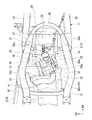
図1は、実施形態に係る鞍乗型車両としてのスクータ型の自動二輪車1の左側面を示す図であり、図2は、車体カバーCV等の一部部品を取り去った自動二輪車1の後半部分の右側面を示す図である。また、図3は、一部部品を取り去った自動二輪車1の中央領域を上方側から見た図である。
自動二輪車1は、車体フレーム11の前部に前輪6と操向ハンドル10を含む操舵系が支持されており、車体フレーム11の中央部に、エンジン2と動力伝達装置3とが一体ブロック化されたパワーユニット4が支持され、車体フレーム11の後部に、乗員が着座するためのシート17が支持されている。パワーユニット4は、前端側が車体フレーム11に上下揺動可能に支持されるとともに、後端部に後輪5が動力伝達可能に支持されている。この実施形態の自動二輪車1では、パワーユニット4と後輪5とが車体フレーム11に揺動可能に支持される所謂ユニットスイング式の後輪支持構造を採用している。なお、パワーユニット4の後端部と車体フレーム11との間には、クッションユニット40が介装されている。
FIG. 1 is a view showing a left side surface of a scooter type motorcycle 1 as a saddle riding type vehicle according to an embodiment, and FIG. 2 is a rear half portion of the motorcycle 1 with some parts such as a vehicle body cover CV removed. FIG. FIG. 3 is a view of the central region of the motorcycle 1 with some parts removed, as viewed from above.
In the motorcycle 1, a steering system including a front wheel 6 and a
車体フレーム11は、ステアリングシャフト9を回動可能に支持するヘッドパイプ12と、ヘッドパイプ12から後部斜め下方に延出するダウンフレーム13と、ダウンフレーム13の下縁の左右の側面に連結され、後方に向けて延出した後に、後部斜め上方に向かって延出する左右一対のサイドフレーム14,14と、サイドフレーム14,14の後部上端に連結され、サイドフレーム14,14の後部と傾斜角度を変えて後部斜め上方に延出する左右一対のシートフレーム15,15と、を備えている。
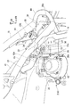
また、図2,図3に示すように、左右のサイドフレーム14,14の後部側上端部の近傍には、前部斜め上方に向かって傾斜しつつ、円弧状に湾曲して左右のサイドフレーム14,14を相互に連結するクロスフレーム49が結合されている。左右のシートフレーム15,15の前端部は、サイドフレーム14,14との連結部よりも前方側に延出し、その前方の延出端がクロスフレーム49の中途部に連結されている。
The
As shown in FIGS. 2 and 3, the left and right side frames 14, 14 are curved in an arc shape in the vicinity of the rear upper ends of the left and right side frames 14, 14 while being inclined obliquely upward toward the front. The
ヘッドパイプ12に支持されるステアリングシャフト9には、前輪6を回転可能に支持する左右のフロントフォーク7,7がブリッジ部材8を介して保持されるとともに、上端部に操向ハンドル10が一体に取り付けられている。
The steering
左右のシートフレーム15,15間には、ヘルメット等の物品を収納可能な収納ボックス34が配置されている。収納ボックス34は、開口が上方に向く状態で左右のシートフレーム15,15に取り付けられている。そして、収納ボックス34の上部には、収納ボックス34の蓋を兼ねる長尺なシート17が前端部を回動支点として回動可能に取り付けられている。
Between the left and right seat frames 15, 15, a
ヘッドパイプ12とシート17の前端部との間には、図1に示すように、車体カバーCVによって下方に凹状に窪む足くぐり空間19が設けられている。足くぐり空間19は、乗員が自動二輪車1に乗り降りする際に足を通す空間であり、その足くぐり空間19の左右両側の下方には、シート17に着座した乗員が足を載せ置くためのステップフロア20,20が設けられている。ステップフロア20,20は、車体フレーム11の左右のサイドフレーム14,14の上方に配置され、足載せ荷重がサイドフレーム14,14によって支持されるようになっている。
Between the
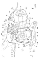
図4は、パワーユニット4の右側面を示す図であり、図5は、パワーユニット4の上面を示す図である。また、図6は、パワーユニット4と車体フレーム11の一部を右側斜め上方側から見た図である。
図2〜図6に示すように、パワーユニット4は、前部側にエンジン2が配置され、エンジン2の左側部後方側に動力伝達装置3が連結されている。そして、動力伝達装置3の後端部に後輪5の支持部が設けられるとともに、動力伝達装置3の上部に、エンジン2の吸気系を構成するエアクリーナ41が設置されている。
FIG. 4 is a diagram showing a right side surface of the
As shown in FIGS. 2 to 6, in the
エンジン2は、図示しないピストンが摺動自在に収容されるシリンダブロック36と、シリンダブロック36の一端に結合されてシリンダブロック36との間に図示しない燃焼室を構成するシリンダヘッド37と、シリンダヘッド37に取り付けられてシリンダヘッド37との間に吸・排気弁の動弁機構を収容するヘッドカバー38と、シリンダブロック36の他端に結合されたクランクケース35と、を備えている。クランクケース35は、ピストンの進退動作を回転動作に変換して出力するクランク軸30を内部に収容し、クランク軸30の左側端部が動力伝達装置3の入力部に対して動力伝達可能とされている。この実施形態では、シリンダブロック36と、シリンダヘッド37と、ヘッドカバー38とがエンジン2のシリンダ部を構成している。
なお、この実施形態のエンジン2の動弁機構は、機関回転(クランク軸30の回転)に連動するカム軸31がシリンダヘッド37の上部に支持され、カム軸31上に設けられた図示しないカムによって吸気弁と排気弁とがそれぞれ所定のタイミングで開閉されるようになっている。
The
In this embodiment, the valve mechanism of the
エンジン2のシリンダ部は、クランクケース35から上方に若干傾斜しつつ車体前方側に向かって突出している。クランクケース35の下方側の前縁部には、車体前方側に向かって突出する一対の支持片35Aが延設されている。この支持片35Aはクランクケース35の車幅方向に離間した2箇所に配置されている。これらの支持片35Aには、一端部が左右のサイドフレーム14,14に連結されたリンク部材14A,14Aの他端部が回動可能に連結される。このエンジン2を含むパワーユニット4の前端側は、これらのリンク部材14A,14Aを介して車体フレーム11に上下揺動可能に支持されている。
The cylinder portion of the
パワーユニット4は、こうしてリンク部材14A,14Aを介して車体フレーム11に取り付けられた状態において、図2,図3に示すように、エンジン2のヘッドカバー38とシリンダヘッド37の一部が左右のサイドフレーム14,14の後端側の立ち上がり部の間から車体前方側に突出している。そして、左右のサイドフレーム14,14の後端側の立ち上がり部の間から突出したヘッドカバー38とシリンダヘッド37の一部とは、左右のシートフレーム15,15の前縁部とクロスフレーム49とに囲まれた空間部内に配置されている。
When the
シリンダ部のうちのシリンダヘッド37の上面側には、図示しない吸気口が設けられ、シリンダヘッド37の下面側には、図示しない排気口が設けられている。吸気口には、インレットパイプ21の前端部が接続され、インレットパイプ21の後端側には、スロットルボディ22を介してコネクティングチューブ23が接続されている。排気口には、図示しないエキゾーストパイプの前端部が接続されており、エキゾーストパイプの後端部は、パワーユニット4の下方から車体後方側に引き出されて、図示しないマフラーに接続されている。
An intake port (not shown) is provided on the upper surface side of the
スロットルボディ22には、内部の通路(吸気通路)を開閉調整するためのスロットル弁24(図中では、スロットル弁の回動軸線のみを示す)と、スロットル弁24の開度を検出する開度センサ25と、が設けられている。また、スロットルボディ22には、スロットル弁24を回動駆動するスロットルモータ26と、スロットルモータ26の回転を減速してスロットル弁24に伝達する減速機構27と、が内蔵されている。開度センサ25で検出されたスロットル弁24の開度信号は、スロットルモータ26を駆動制御する図示しない制御装置の信号入力部に入力される。制御装置は、操向ハンドル10に設けられたスロットル操作子(図示せず)の操作信号と開度センサ25の開度信号とその他の各種の信号を受け、スロットル弁24の吸気開度を適正開度に調整するようにスロットルモータ26を駆動制御する。
The
また、インレットパイプ21のシリンダヘッド37との接続部の近傍には、制御装置からの制御信号を受けて通路(吸気通路)内に燃料を噴射する燃料噴射弁28が設置されている。なお、図中符号28aは、燃料噴射弁28に接続される燃料供給パイプである。
この実施形態においては、インレットパイプ21と、スロットルボディ22の内部通路と、コネクティングチューブ23とがエンジン2の吸気通路を構成している。
A
In this embodiment, the
ところで、インレットパイプ21はシリンダブロック36の上方からシリンダヘッド37の上方に向かって緩やかに下方に傾斜し、シリンダヘッド37上の吸気口の直上部の付近で急激に下方に湾曲して吸気口に接続されている。インレットパイプ21の後端部に接続されたスロットルボディ22は、シリンダヘッド37とクランクケース35の各上面の上方に跨って配置され、スロットルボディ22の後端部に接続されたコネクティングチューブ23は、クランクケース35の上面の上方を経由してエアクリーナ41に接続されている。
この実施形態においては、スロットルボディ22内のスロットル弁24は、図3,図5に示すように、車両の平面視において、シリンダブロック36(シリンダ部)の上面と重なる位置に配置されている。
By the way, the
In this embodiment, as shown in FIGS. 3 and 5, the
スロットルボディ22に一体に組み付けられるスロットルモータ26は、スロットルボディ22内のスロットル弁24の軸心位置よりも後部下方側に偏倚した位置に配置されている。ここで、スロットル弁24とスロットルモータ26の各軸心は、スロットルボディ22内の通路(吸気通路)の軸心22Cと略直交するように配置されている。また、スロットルモータ26の回転を減速してスロットル弁24に伝達する減速機構27は、スロットルボディ22内の通路(吸気通路)の軸心22Cを挟んで車体左側に偏った位置に配置されている。
The
また、クランクケース35内のクランク軸30とシリンダヘッド37の上部のカム軸31とは、エンジン2の内部においてタイミングチェーン32によって連動可能と連係されている。具体的には、クランク軸30とカム軸31には、それぞれ図示しないスプロケットが取り付けられ、両スプロケットにタイミングチェーン32が掛け渡されている。タイミングチェーン32は、図5に示すように、車両の平面視において、シリンダブロック36の車幅方向の中心線C1を挟んで車両の右側に偏った位置に配置されている。
Further, the
シリンダブロック36の上壁のタイミングチェーン32の通過軌道の上方位置には、タイミングチェーン32の張力を調整するためのチェーンテンショナ33が設置されている。チェーンテンショナ33は、シリンダブロック36の上面からその一部が上方に突出し、その突出した部分を工具等で操作することによってタイミングチェーン32の張力をエンジン2の外部から調整し得るようになっている。チェーンテンショナ33の上方側への最大突出部33aは、車両の平面視でチェーンテンショナ33のほぼ中心部に位置されている。
A
スロットルボディ22内のスロットル弁24は、シリンダブロック36上のチェーンテンショナ33の最大突出部33aよりも僅かに前方側位置に配置されている。また、スロットルボディ22に一体に組み付けられたスロットルモータ26は、車両の側面視において、エンジン2の上面とスロットルボディ22の内部通路(吸気通路)との間に位置されている。
The
スロットルモータ26は、さらに、図4に示すように、車両の側面視において、スロットルモータ26の下端を通る水平線H1がチェーンテンショナ33と上下方向で重なり、かつスロットルモータ26の軸心部26aがチェーンテンショナ33の後方側に所定量ずれた位置に配置されている。また、スロットルモータ26は、クランクケース35の上面から上方に隆起する前壁35aと、シリンダブロック36上のチェーンテンショナ33とに車両前後方向で挟まれた位置に配置されている。
さらに、スロットルモータ26は、図3,図5に示すように、平面視でチェーンテンショナ33上の最大突出部33aよりも後方側領域(最大突出部33aからずれた領域)と一部が重なるように配置されている。
Further, as shown in FIG. 4, the
Further, as shown in FIGS. 3 and 5, the
ここで、インレットパイプ21の前端部は、シリンダヘッド37の上面のうちの、シリンダブロック36の車幅方向の中心線C1を挟んで車両の左側に偏った位置で吸気口に接続されている。インレットパイプ21とスロットルボディ22の内部通路は、図5に示すように、インレットパイプ21の前端側のシリンダヘッド37との接続部から中心線C1を跨いで右斜め後方側に傾斜している。したがって、スロットル弁24が配置されるスロットルボディ22の内部通路の軸心22Cは、車両の平面視において、右斜め後方側に傾斜している。
Here, the front end portion of the
ただし、スロットルボディ22の内部通路の軸心22Cは、チェーンテンショナ33の最大突出部33aの左側を横切って後方に延びている。そして、この状態において、スロットルボディ22内の減速機構27は、車両の平面視において、内部通路の軸心22Cを挟んでチェーンテンショナ33の最大突出部33aと反対側に配置されている。
However, the
また、コネクティングチューブ23の後端部が接続されるエアクリーナ41は、図3に示すように、車両の平面視において、インレットパイプ21の前端部と同様にチェーンテンショナ33の最大突出部33aよりも左側に配置されている。このため、内部通路の軸心22Cが、シリンダブロック36の車幅方向の中心線C1よりも右側位置で、右斜め後方側に傾斜するスロットルボディ22の後端部には、コネクティングチューブ23の前端部が水平方向に大きく蛇行して接続されている。コネクティングチューブ23は、エアクリーナ41側の接続部とスロットルボディ22側の接続部の車幅方向のずれ分よりも大きく車幅方向に蛇行している。
Further, as shown in FIG. 3, the
また、エンジン2のクランクケース35の右側端部には、図5に示すように、エンジン冷却水を冷却するためのラジエータ50が取り付けられている。なお、ラジエータ50は、図5以外の図面においては図示を省略されている。また、図中符号43は、ラジエータ50を取り付けるためにクランクケース35に一体に設けられたラジエータベースである。このラジエータベース43の上部はクランクケース35の一般部の上面よりも上方側に突出している。ラジエータベース43の上部には、ラジエータ50を冷却した空気をクランクケース35の一般面の上方側を通して車体後方側に排出するための排風口43aが設けられている。
Further, as shown in FIG. 5, a
また、スロットルボディ22に一体に組み付けられるスロットルモータ26は、クランクケース35の一般部の上面の上方に位置されるとともに、クランクケース35の上面から上方に隆起する前壁35a(図3,図4参照)よりも前方側に位置されている。また、スロットルモータ26は、クランクケース35の排風口43aの車体前方側に隣接して配置されている。したがって、スロットルモータ26は、車両の側面視において、排風口43aの車体前方側に隣接し、かつチェーンテンショナ33の車体後方側に隣接する位置に配置されている。
Further, the
以上のように、この実施形態の自動二輪車1においては、スロットルボディ22に設けられるスロットルモータ26が、車両の側面視において、スロットルモータ26の下端を通る水平線H1がチェーンテンショナ33と上下方向で重なり、かつスロットルモータ26の軸心部26aがチェーンテンショナ33と前後方向にずれるように(チェーンテンショナ33の後方側にずれて)配置されているため、スロットルモータ26を、チェーンテンショナ33と適切な間隔を維持してエンジン2の上面と吸気通路の間にコンパクトに配置することができる。
したがって、この自動二輪車においては、吸気通路をエンジン2に近づけて、収納ボックス34等のエンジン2の周囲の機能部品のレイアウトの自由度を高めることができる。
As described above, in the motorcycle 1 of this embodiment, the
Therefore, in this motorcycle, the intake passage can be brought close to the
そして、この実施形態の自動二輪車1の場合、クランクケース35の上面から上方に隆起する前壁35aとチェーンテンショナ33とに挟まれる車体前後方向の僅かな空間を利用してスロットルモータ26が配置されているため、吸気通路の高さ位置をより低く抑えることができる。
In the motorcycle 1 of this embodiment, the
また、この実施形態の自動二輪車1においては、クランクケース35の下方側の前縁部に突設された支持片35A部分で、パワーユニット4が車体フレーム11に上下揺動可能に支持されているため、パワーユニット4の上方側の前縁部が車体フレーム11に上下揺動可能に支持される場合に比較して、パワーユニット4の枢支位置が吸気通路やスロットルモータ26から離間することになる。したがって、パワーユニット4のこの支持構造を採用することにより、スロットルモータ26の配置スペースをより容易に確保することができる。
Further, in the motorcycle 1 of this embodiment, the
さらに、この実施形態の自動二輪車1では、スロットルボディ22内の減速機構27が、車両の平面視において、スロットルボディ22内の軸心22Aを挟んでチェーンテンショナ33の最大突出部33aと反対側に配置されていることから、容積の大きい減速機構27とチェーンテンショナ33のそれぞれの突出部分を相互に離間して配置することができる。したがって、この配置を採用することにより、吸気通路をエンジン2の上面により近接させて配置することが可能になる。
Furthermore, in the motorcycle 1 of this embodiment, the
また、この実施形態の自動二輪車1においては、スロットル弁24がシリンダブロック36の上面の上方に配置され、スロットルモータ26の軸心部26aがクランクケース35の一般部の上面の上方に配置されていることから、スロットルモータ26をシリンダブロック36上の狭いスペースに無理に配置する場合に比較して、吸気通路の前端側をシリンダブロック36とシリンダヘッド37の上面により近づけて配置することが可能になる。したがって、この構造を採用することにより、吸気通路をエンジン2の上面に近接させるうえで有利となる。
In the motorcycle 1 of this embodiment, the
また、特に、この実施形態の自動二輪車1においては、スロットルモータ26が、クランクケース35の側部上方に突設されるラジエータ50の排風口43aの車体前方側に隣接し、かつ、チェーンテンショナ33の車体後方側に隣接する位置に配置されているため、排風口43aとチェーンテンショナ33の間のデッドスペースを有効利用して、スロットルモータ26をエンジン2と吸気通路の間にコンパクトに配置することができる。
さらに、この実施形態の場合、スロットルモータ26の右側の後部側方が、クランクケース35の排風口43aとラジエータ50とによって覆われるため、スロットルモータ26を外部から有効に保護できる、という利点もある。
Further, in particular, in the motorcycle 1 of this embodiment, the
Furthermore, in the case of this embodiment, since the rear side of the right side of the
さらに、この実施形態の自動二輪車1においては、スロットルモータ26が、平面視で、チェーンテンショナ33の最大突出部33aからずれた位置でチェーンテンショナ33の一部と重なるように配置されているため、スロットルモータ26とチェーンテンショナ33の離間距離を確保しつつ、吸気通路を蛇行させて吸気通路を最適管長に容易に設定することができる。したがって、この構造を採用することにより、エンジン2の吸気効率を容易に高めることができる。
Furthermore, in the motorcycle 1 of this embodiment, the
なお、この発明は上記の実施形態に限定されるものではなく、その要旨を逸脱しない範囲で種々の設計変更が可能である。例えば、上記の実施形態においては、スロットルモータ26がスロットルボディ22のブロックに一体に組み付けられているが、スロットルモータ26は、スロットル弁24を収容するブロックと別体に構成するようにしても良い。
また、本明細書における鞍乗型車両には、運転者が車体を跨いで乗車する車両全般が含まれる。本明細書における鞍乗型車両には、自動二輪車(原動機付自転車及びスクータ型車両を含む)のみならず、三輪(前一輪かつ後二輪の他に、前二輪かつ後一輪の車両も含む)または四輪の車両も含まれる。
In addition, this invention is not limited to said embodiment, A various design change is possible in the range which does not deviate from the summary. For example, in the above embodiment, the
In addition, the saddle riding type vehicle in this specification includes all vehicles on which a driver rides across a vehicle body. The saddle riding type vehicle in this specification includes not only motorcycles (including motorbikes and scooter type vehicles) but also three wheels (including front two wheels and one rear wheel in addition to front one wheel and rear two wheels) or Four-wheel vehicles are also included.
1…自動二輪車(鞍乗型車両)
2…エンジン
11…車体フレーム
21…インレットパイプ(吸気通路)
22…スロットルボディ(吸気通路)
22C…軸心
23…コネクティングチューブ(吸気通路)
24…スロットル弁
26…スロットルモータ
26a…軸心部
27…減速機構
32…タイミングチェーン
33…チェーンテンショナ
33a…最大突出部
35…クランクケース
36…シリンダブロック(シリンダ部)
37…シリンダヘッド(シリンダ部)
38…ヘッドカバー(シリンダ部)
41…エアクリーナ
43a…排風口
50…ラジエータ
1 ... Motorcycle (saddle-type vehicle)
2 ...
22 ... Throttle body (intake passage)
22C ...
24 ...
37 ... Cylinder head (cylinder part)
38 ... Head cover (cylinder part)
41 ... Air cleaner 43a ...
Claims (6)
前記シリンダ部(36,37,38)の上部後方側から車体前方側に延出して、前端部が下方に湾曲して前記シリンダ部(36,37,38)の吸気口に接続される吸気通路(21,22,23)と、
前記吸気通路(21,22,23)に設けられ、前記吸気通路(21,22,23)を流通する吸気量を調整するスロットル弁(24)と、
前記スロットル弁(24)を駆動するスロットルモータ(26)と、
前記エンジン(2)内のタイミングチェーン(32)の張力を調整する部品であり、その一部が前記シリンダ部(36,37,38)の上面から上方に突出するチェーンテンショナ(33)と、を備え、
前記スロットル弁(24)が、車両の平面視において、前記シリンダ部(36,37,38)の上面と重なる位置に配置される鞍乗型車両であって、
前記スロットルモータ(26)は、車両の側面視において、前記エンジン(2)の上面と前記吸気通路(21,22,23)との間の位置で、前記スロットルモータ(26)の下端を通る水平線(H1)が前記チェーンテンショナ(33)と重なる位置に配置され、かつ前記スロットルモータ(26)の軸心部(26a)が前記チェーンテンショナ(33)と前後方向にずれるように、かつ車両前後方向でクランクケース(35)の上面から上方に隆起する前壁(35a)と前記チェーンテンショナ(33)との間に、配置されていることを特徴とする鞍乗型車両。 An engine (2) attached to the vehicle body frame (11) such that the cylinder portions (36, 37, 38) extend toward the front of the vehicle body;
An intake passage that extends from the upper rear side of the cylinder part (36, 37, 38) to the front side of the vehicle body and has a front end curved downward and connected to the intake port of the cylinder part (36, 37, 38). (21, 22, 23),
A throttle valve (24) that is provided in the intake passage (21, 22, 23) and adjusts the amount of intake air flowing through the intake passage (21, 22, 23);
A throttle motor (26) for driving the throttle valve (24);
A chain tensioner (33), which is a part for adjusting the tension of the timing chain (32) in the engine (2), and a part of which projects upward from the upper surface of the cylinder part (36, 37, 38). Prepared,
The throttle valve (24) is a straddle-type vehicle disposed at a position overlapping the upper surface of the cylinder part (36, 37, 38) in a plan view of the vehicle,
The throttle motor (26) is a horizontal line passing through the lower end of the throttle motor (26) at a position between the upper surface of the engine (2) and the intake passage (21, 22, 23) in a side view of the vehicle. (H1) is disposed at a position overlapping with the chain tensioner (33), and the axial center of the throttle motor (26) and in so that the deviation in the longitudinal direction (26a) is the chain tensioner (33), and the vehicle longitudinal The straddle-type vehicle is disposed between a front wall (35a) protruding upward from the upper surface of the crankcase (35) in the direction and the chain tensioner (33) .
前記減速機構(27)は、車両の平面視において、前記吸気通路(21,22,23)の軸心(22C)を挟んで前記チェーンテンショナ(33)の最大突出部(33a)と反対側に配置されていることを特徴とする請求項1または2に記載の鞍乗型車両。 The throttle motor (26) is connected to the throttle valve (24) via a speed reduction mechanism (27) so that power can be transmitted,
The speed reduction mechanism (27) is opposite to the maximum protrusion (33a) of the chain tensioner (33) across the axis (22C) of the intake passage (21, 22, 23) in plan view of the vehicle. The straddle-type vehicle according to claim 1 or 2, wherein the straddle-type vehicle is disposed .
前記スロットルモータ(26)の軸心部(26a)は、前記エンジン(2)のクランクケース(35)の上方に配置されていることを特徴とする請求項1〜3のいずれか1項に記載の鞍乗型車両。 The throttle valve (24) is disposed above the upper surface of the cylinder part (36, 37, 38),
The shaft center part (26a) of the throttle motor (26) is disposed above a crankcase (35) of the engine (2), according to any one of claims 1 to 3. Saddle riding type vehicle.
前記スロットルモータ(26)は、前記排風口(43a)の車体前方側に隣接する位置に配置されていることを特徴とする請求項1〜4のいずれか1項に記載の鞍乗型車両。 The crankcase (35) of the engine (2) is provided with an exhaust port (43a) of a radiator (50) attached to the crankcase (35) protruding upward.
The straddle-type vehicle according to any one of claims 1 to 4, wherein the throttle motor (26) is disposed at a position adjacent to the front side of the vehicle body of the exhaust port (43a) .
Priority Applications (4)
| Application Number | Priority Date | Filing Date | Title |
|---|---|---|---|
| JP2014059069A JP6155213B2 (en) | 2014-03-20 | 2014-03-20 | Saddle riding vehicle |
| CN201580014545.0A CN106103943B (en) | 2014-03-20 | 2015-03-18 | Straddle-type vehicle |
| EP15765033.4A EP3121421B1 (en) | 2014-03-20 | 2015-03-18 | Straddled vehicle |
| PCT/JP2015/058141 WO2015141749A1 (en) | 2014-03-20 | 2015-03-18 | Straddled vehicle |
Applications Claiming Priority (1)
| Application Number | Priority Date | Filing Date | Title |
|---|---|---|---|
| JP2014059069A JP6155213B2 (en) | 2014-03-20 | 2014-03-20 | Saddle riding vehicle |
Publications (3)
| Publication Number | Publication Date |
|---|---|
| JP2015183538A JP2015183538A (en) | 2015-10-22 |
| JP2015183538A5 JP2015183538A5 (en) | 2017-01-05 |
| JP6155213B2 true JP6155213B2 (en) | 2017-06-28 |
Family
ID=54144713
Family Applications (1)
| Application Number | Title | Priority Date | Filing Date |
|---|---|---|---|
| JP2014059069A Active JP6155213B2 (en) | 2014-03-20 | 2014-03-20 | Saddle riding vehicle |
Country Status (4)
| Country | Link |
|---|---|
| EP (1) | EP3121421B1 (en) |
| JP (1) | JP6155213B2 (en) |
| CN (1) | CN106103943B (en) |
| WO (1) | WO2015141749A1 (en) |
Families Citing this family (4)
| Publication number | Priority date | Publication date | Assignee | Title |
|---|---|---|---|---|
| EP3499006B1 (en) * | 2016-08-10 | 2021-03-03 | Honda Motor Co., Ltd. | Saddle-type vehicle |
| WO2019186923A1 (en) * | 2018-03-29 | 2019-10-03 | 本田技研工業株式会社 | Saddle riding-type vehicle |
| WO2019186922A1 (en) * | 2018-03-29 | 2019-10-03 | 本田技研工業株式会社 | Straddle-type vehicle |
| JP2020148132A (en) * | 2019-03-13 | 2020-09-17 | ヤマハ発動機株式会社 | Saddle riding type vehicle |
Family Cites Families (10)
| Publication number | Priority date | Publication date | Assignee | Title |
|---|---|---|---|---|
| JP3184040B2 (en) * | 1994-03-15 | 2001-07-09 | 本田技研工業株式会社 | Cam drive member lubrication device for 4-cycle internal combustion engine |
| JP3539584B2 (en) * | 1994-12-28 | 2004-07-07 | ヤマハ発動機株式会社 | Scooter type motorcycle |
| JP4512025B2 (en) * | 2005-11-09 | 2010-07-28 | 本田技研工業株式会社 | Motorcycle |
| JP5014047B2 (en) * | 2007-09-29 | 2012-08-29 | 本田技研工業株式会社 | Arrangement structure of shift actuator in saddle-ride type vehicle power unit |
| JP4887349B2 (en) * | 2008-11-28 | 2012-02-29 | 本田技研工業株式会社 | Saddle riding |
| JP2010236519A (en) * | 2009-03-31 | 2010-10-21 | Honda Motor Co Ltd | Internal combustion engine |
| JP5184503B2 (en) * | 2009-12-24 | 2013-04-17 | 本田技研工業株式会社 | Saddle riding vehicle |
| JP5519302B2 (en) * | 2010-01-19 | 2014-06-11 | 本田技研工業株式会社 | Saddle riding vehicle |
| JP5546878B2 (en) * | 2010-01-19 | 2014-07-09 | 本田技研工業株式会社 | Saddle riding vehicle |
| JP5578999B2 (en) * | 2010-09-17 | 2014-08-27 | 本田技研工業株式会社 | Saddle riding vehicle |
-
2014
- 2014-03-20 JP JP2014059069A patent/JP6155213B2/en active Active
-
2015
- 2015-03-18 EP EP15765033.4A patent/EP3121421B1/en active Active
- 2015-03-18 WO PCT/JP2015/058141 patent/WO2015141749A1/en active Application Filing
- 2015-03-18 CN CN201580014545.0A patent/CN106103943B/en active Active
Also Published As
| Publication number | Publication date |
|---|---|
| EP3121421A4 (en) | 2017-12-06 |
| CN106103943B (en) | 2019-04-19 |
| EP3121421A1 (en) | 2017-01-25 |
| JP2015183538A (en) | 2015-10-22 |
| WO2015141749A1 (en) | 2015-09-24 |
| EP3121421B1 (en) | 2019-03-06 |
| CN106103943A (en) | 2016-11-09 |
Similar Documents
| Publication | Publication Date | Title |
|---|---|---|
| JP5546878B2 (en) | Saddle riding vehicle | |
| JP6012483B2 (en) | Exhaust device for saddle riding type vehicle | |
| JP5519302B2 (en) | Saddle riding vehicle | |
| JP6155213B2 (en) | Saddle riding vehicle | |
| US9994286B2 (en) | Straddle type vehicle | |
| JP5184503B2 (en) | Saddle riding vehicle | |
| JP2007302169A (en) | Saddle riding type irregular ground traveling vehicle | |
| JP6543851B2 (en) | Saddle-ride type vehicle | |
| JP7338145B2 (en) | straddle-type vehicle | |
| JP5227839B2 (en) | Intake device structure for saddle-ride type vehicles | |
| JP2009101893A (en) | Intake device for scooter-type vehicle | |
| JP4049166B2 (en) | Scooter type motorcycle | |
| JP5806830B2 (en) | Saddle riding vehicle | |
| JP3941803B2 (en) | Scooter-type vehicle intake system | |
| JP2006096200A (en) | Motorcycle | |
| JP6094904B2 (en) | Motorcycle | |
| JP5869611B2 (en) | Saddle riding vehicle | |
| JP5856215B2 (en) | Saddle riding vehicle | |
| JP6049107B2 (en) | Internal combustion engine for saddle-ride type vehicles | |
| JP5625574B2 (en) | Accelerator position sensor arrangement structure for motorcycles | |
| JP5834867B2 (en) | Intake control device | |
| JP6682813B2 (en) | Cooling system mechanism for saddle type vehicles | |
| JP4049165B2 (en) | Scooter type motorcycle | |
| JP2023030244A (en) | Saddle-riding type vehicle | |
| JP4990058B2 (en) | Fuel injection valve mounting structure for small vehicle engine |
Legal Events
| Date | Code | Title | Description |
|---|---|---|---|
| A521 | Request for written amendment filed |
Free format text: JAPANESE INTERMEDIATE CODE: A523 Effective date: 20161118 |
|
| A621 | Written request for application examination |
Free format text: JAPANESE INTERMEDIATE CODE: A621 Effective date: 20161118 |
|
| TRDD | Decision of grant or rejection written | ||
| A01 | Written decision to grant a patent or to grant a registration (utility model) |
Free format text: JAPANESE INTERMEDIATE CODE: A01 Effective date: 20170509 |
|
| A61 | First payment of annual fees (during grant procedure) |
Free format text: JAPANESE INTERMEDIATE CODE: A61 Effective date: 20170605 |
|
| R150 | Certificate of patent or registration of utility model |
Ref document number: 6155213 Country of ref document: JP Free format text: JAPANESE INTERMEDIATE CODE: R150 |
|
| R250 | Receipt of annual fees |
Free format text: JAPANESE INTERMEDIATE CODE: R250 |
|
| R250 | Receipt of annual fees |
Free format text: JAPANESE INTERMEDIATE CODE: R250 |
|
| S111 | Request for change of ownership or part of ownership |
Free format text: JAPANESE INTERMEDIATE CODE: R313115 |
|
| R360 | Written notification for declining of transfer of rights |
Free format text: JAPANESE INTERMEDIATE CODE: R360 |
|
| R360 | Written notification for declining of transfer of rights |
Free format text: JAPANESE INTERMEDIATE CODE: R360 |
|
| R371 | Transfer withdrawn |
Free format text: JAPANESE INTERMEDIATE CODE: R371 |
|
| S111 | Request for change of ownership or part of ownership |
Free format text: JAPANESE INTERMEDIATE CODE: R313115 |
|
| R350 | Written notification of registration of transfer |
Free format text: JAPANESE INTERMEDIATE CODE: R350 |
|
| R250 | Receipt of annual fees |
Free format text: JAPANESE INTERMEDIATE CODE: R250 |
|
| R250 | Receipt of annual fees |
Free format text: JAPANESE INTERMEDIATE CODE: R250 |
|
| R250 | Receipt of annual fees |
Free format text: JAPANESE INTERMEDIATE CODE: R250 |