JP6131277B2 - Automotive selective contact reduction (SCR) system sensor holder and assembly - Google Patents
Automotive selective contact reduction (SCR) system sensor holder and assembly Download PDFInfo
- Publication number
- JP6131277B2 JP6131277B2 JP2014560040A JP2014560040A JP6131277B2 JP 6131277 B2 JP6131277 B2 JP 6131277B2 JP 2014560040 A JP2014560040 A JP 2014560040A JP 2014560040 A JP2014560040 A JP 2014560040A JP 6131277 B2 JP6131277 B2 JP 6131277B2
- Authority
- JP
- Japan
- Prior art keywords
- outlet
- inlet
- sensor
- scr system
- scr
- Prior art date
- Legal status (The legal status is an assumption and is not a legal conclusion. Google has not performed a legal analysis and makes no representation as to the accuracy of the status listed.)
- Active
Links
Images


Classifications
-
- F—MECHANICAL ENGINEERING; LIGHTING; HEATING; WEAPONS; BLASTING
- F16—ENGINEERING ELEMENTS AND UNITS; GENERAL MEASURES FOR PRODUCING AND MAINTAINING EFFECTIVE FUNCTIONING OF MACHINES OR INSTALLATIONS; THERMAL INSULATION IN GENERAL
- F16L—PIPES; JOINTS OR FITTINGS FOR PIPES; SUPPORTS FOR PIPES, CABLES OR PROTECTIVE TUBING; MEANS FOR THERMAL INSULATION IN GENERAL
- F16L55/00—Devices or appurtenances for use in, or in connection with, pipes or pipe systems
-
- F—MECHANICAL ENGINEERING; LIGHTING; HEATING; WEAPONS; BLASTING
- F01—MACHINES OR ENGINES IN GENERAL; ENGINE PLANTS IN GENERAL; STEAM ENGINES
- F01N—GAS-FLOW SILENCERS OR EXHAUST APPARATUS FOR MACHINES OR ENGINES IN GENERAL; GAS-FLOW SILENCERS OR EXHAUST APPARATUS FOR INTERNAL COMBUSTION ENGINES
- F01N3/00—Exhaust or silencing apparatus having means for purifying, rendering innocuous, or otherwise treating exhaust
- F01N3/08—Exhaust or silencing apparatus having means for purifying, rendering innocuous, or otherwise treating exhaust for rendering innocuous
- F01N3/10—Exhaust or silencing apparatus having means for purifying, rendering innocuous, or otherwise treating exhaust for rendering innocuous by thermal or catalytic conversion of noxious components of exhaust
- F01N3/18—Exhaust or silencing apparatus having means for purifying, rendering innocuous, or otherwise treating exhaust for rendering innocuous by thermal or catalytic conversion of noxious components of exhaust characterised by methods of operation; Control
- F01N3/20—Exhaust or silencing apparatus having means for purifying, rendering innocuous, or otherwise treating exhaust for rendering innocuous by thermal or catalytic conversion of noxious components of exhaust characterised by methods of operation; Control specially adapted for catalytic conversion ; Methods of operation or control of catalytic converters
- F01N3/2066—Selective catalytic reduction [SCR]
- F01N3/208—Control of selective catalytic reduction [SCR], e.g. dosing of reducing agent
-
- F—MECHANICAL ENGINEERING; LIGHTING; HEATING; WEAPONS; BLASTING
- F16—ENGINEERING ELEMENTS AND UNITS; GENERAL MEASURES FOR PRODUCING AND MAINTAINING EFFECTIVE FUNCTIONING OF MACHINES OR INSTALLATIONS; THERMAL INSULATION IN GENERAL
- F16L—PIPES; JOINTS OR FITTINGS FOR PIPES; SUPPORTS FOR PIPES, CABLES OR PROTECTIVE TUBING; MEANS FOR THERMAL INSULATION IN GENERAL
- F16L37/00—Couplings of the quick-acting type
- F16L37/08—Couplings of the quick-acting type in which the connection between abutting or axially overlapping ends is maintained by locking members
- F16L37/12—Couplings of the quick-acting type in which the connection between abutting or axially overlapping ends is maintained by locking members using hooks, pawls or other movable or insertable locking members
- F16L37/14—Joints secured by inserting between mating surfaces an element, e.g. a piece of wire, a pin, a chain
- F16L37/142—Joints secured by inserting between mating surfaces an element, e.g. a piece of wire, a pin, a chain where the securing element is inserted tangentially
- F16L37/144—Joints secured by inserting between mating surfaces an element, e.g. a piece of wire, a pin, a chain where the securing element is inserted tangentially the securing element being U-shaped
-
- F—MECHANICAL ENGINEERING; LIGHTING; HEATING; WEAPONS; BLASTING
- F01—MACHINES OR ENGINES IN GENERAL; ENGINE PLANTS IN GENERAL; STEAM ENGINES
- F01N—GAS-FLOW SILENCERS OR EXHAUST APPARATUS FOR MACHINES OR ENGINES IN GENERAL; GAS-FLOW SILENCERS OR EXHAUST APPARATUS FOR INTERNAL COMBUSTION ENGINES
- F01N2610/00—Adding substances to exhaust gases
- F01N2610/02—Adding substances to exhaust gases the substance being ammonia or urea
-
- F—MECHANICAL ENGINEERING; LIGHTING; HEATING; WEAPONS; BLASTING
- F01—MACHINES OR ENGINES IN GENERAL; ENGINE PLANTS IN GENERAL; STEAM ENGINES
- F01N—GAS-FLOW SILENCERS OR EXHAUST APPARATUS FOR MACHINES OR ENGINES IN GENERAL; GAS-FLOW SILENCERS OR EXHAUST APPARATUS FOR INTERNAL COMBUSTION ENGINES
- F01N2610/00—Adding substances to exhaust gases
- F01N2610/14—Arrangements for the supply of substances, e.g. conduits
- F01N2610/148—Arrangement of sensors
-
- F—MECHANICAL ENGINEERING; LIGHTING; HEATING; WEAPONS; BLASTING
- F01—MACHINES OR ENGINES IN GENERAL; ENGINE PLANTS IN GENERAL; STEAM ENGINES
- F01N—GAS-FLOW SILENCERS OR EXHAUST APPARATUS FOR MACHINES OR ENGINES IN GENERAL; GAS-FLOW SILENCERS OR EXHAUST APPARATUS FOR INTERNAL COMBUSTION ENGINES
- F01N2610/00—Adding substances to exhaust gases
- F01N2610/14—Arrangements for the supply of substances, e.g. conduits
- F01N2610/1486—Means to prevent the substance from freezing
-
- F—MECHANICAL ENGINEERING; LIGHTING; HEATING; WEAPONS; BLASTING
- F01—MACHINES OR ENGINES IN GENERAL; ENGINE PLANTS IN GENERAL; STEAM ENGINES
- F01N—GAS-FLOW SILENCERS OR EXHAUST APPARATUS FOR MACHINES OR ENGINES IN GENERAL; GAS-FLOW SILENCERS OR EXHAUST APPARATUS FOR INTERNAL COMBUSTION ENGINES
- F01N2900/00—Details of electrical control or of the monitoring of the exhaust gas treating apparatus
- F01N2900/06—Parameters used for exhaust control or diagnosing
- F01N2900/18—Parameters used for exhaust control or diagnosing said parameters being related to the system for adding a substance into the exhaust
- F01N2900/1806—Properties of reducing agent or dosing system
-
- Y—GENERAL TAGGING OF NEW TECHNOLOGICAL DEVELOPMENTS; GENERAL TAGGING OF CROSS-SECTIONAL TECHNOLOGIES SPANNING OVER SEVERAL SECTIONS OF THE IPC; TECHNICAL SUBJECTS COVERED BY FORMER USPC CROSS-REFERENCE ART COLLECTIONS [XRACs] AND DIGESTS
- Y02—TECHNOLOGIES OR APPLICATIONS FOR MITIGATION OR ADAPTATION AGAINST CLIMATE CHANGE
- Y02A—TECHNOLOGIES FOR ADAPTATION TO CLIMATE CHANGE
- Y02A50/00—TECHNOLOGIES FOR ADAPTATION TO CLIMATE CHANGE in human health protection, e.g. against extreme weather
- Y02A50/20—Air quality improvement or preservation, e.g. vehicle emission control or emission reduction by using catalytic converters
-
- Y—GENERAL TAGGING OF NEW TECHNOLOGICAL DEVELOPMENTS; GENERAL TAGGING OF CROSS-SECTIONAL TECHNOLOGIES SPANNING OVER SEVERAL SECTIONS OF THE IPC; TECHNICAL SUBJECTS COVERED BY FORMER USPC CROSS-REFERENCE ART COLLECTIONS [XRACs] AND DIGESTS
- Y02—TECHNOLOGIES OR APPLICATIONS FOR MITIGATION OR ADAPTATION AGAINST CLIMATE CHANGE
- Y02T—CLIMATE CHANGE MITIGATION TECHNOLOGIES RELATED TO TRANSPORTATION
- Y02T10/00—Road transport of goods or passengers
- Y02T10/10—Internal combustion engine [ICE] based vehicles
- Y02T10/12—Improving ICE efficiencies
Description
本開示は、自動車選択的接触還元(SCR)システムに関し、より特定的にはSCRラインアセンブリにおけるセンサの使用に関する。 The present disclosure relates to automotive selective catalytic reduction (SCR) systems, and more particularly to the use of sensors in SCR line assemblies.
背景
ディーゼル機関を有する自動車には、エンジンの排気中の窒素酸化物(NOx)の量を減らすために使用される選択的接触還元(SCR)排気処理システムが多くの場合に設けられる。一般的に、SCRシステムにおいては、NOxを窒素および水に変換する化学反応を起こすために、尿素またはディーゼル排気流体(DEF)などの還元剤がエンジン排気流に注入される。タンク内に保持される還元剤の特性を感知するために、尿素品質センサなどのセンサがSCRシステムタンク内に設置される場合がある。尿素またはDEFを還元剤として使用する場合に直面する1つの難点は、この還元剤が−11℃周辺で凍結することから、タンク内に保存した場合に寒冷気候においてその特性を感知することが難しくなり得る点にある。
BACKGROUND Automobiles with diesel engines are often provided with a selective catalytic reduction (SCR) exhaust treatment system that is used to reduce the amount of nitrogen oxides (NO x ) in the engine exhaust. Typically, in an SCR system, a reducing agent such as urea or diesel exhaust fluid (DEF) is injected into the engine exhaust stream to cause a chemical reaction that converts NO x to nitrogen and water. A sensor such as a urea quality sensor may be installed in the SCR system tank to sense the characteristics of the reducing agent held in the tank. One difficulty faced when using urea or DEF as a reducing agent is that the reducing agent freezes around −11 ° C., making it difficult to sense its properties in cold climates when stored in tanks. It can be a point.
概要
本発明の局面に従えば、自動車選択的接触還元(SCR)システムのセンサ保持部が提供される。保持部は、管と、チャンバと、リテーナとを含む。管は、第1のSCRラインから入る流体を受ける入口を有するとともに、出る流体を第2のSCRラインへ導く出口を有する。管は、入口と出口との間に延在する通路も有する。チャンバは、SCRシステムセンサを受けるための通路にアクセス可能な内部を有する。チャンバは、内部へ通じる開口を有する。リテーナは、チャンバの開口において移動可能な部分を有する。この部分が開口内において内部へ向けて移動すると、この部分はSCRシステムのセンサに当接し、保持部内においてセンサを保持する。そして、この部分が内部から離れる方向へ移動すると、SCRシステムセンサが保持部から解除され得る。
SUMMARY According to an aspect of the present invention, a sensor holding part of an automobile selective catalytic reduction (SCR) system is provided. The holding part includes a tube, a chamber, and a retainer. The tube has an inlet for receiving fluid entering from the first SCR line and an outlet for directing outgoing fluid to the second SCR line. The tube also has a passage extending between the inlet and the outlet. The chamber has an interior accessible to a passage for receiving the SCR system sensor. The chamber has an opening leading to the interior. The retainer has a movable portion at the opening of the chamber. When this part moves inward in the opening, this part abuts on the sensor of the SCR system and holds the sensor in the holding part. When this part moves away from the inside, the SCR system sensor can be released from the holding unit.
本発明の他の局面に従えば、自動車選択的接触還元(SCR)システムのアセンブリが提供される。アセンブリは、保持部と、入口接続部と、出口接続部と、第1のSCRラインと、第2のSCRラインとを含む。保持部は、管と、チャンバと、加熱要素とを含む。管は、入口と、出口と、入口と出口との間に延在する通路とを有する。チャンバは、通路にアクセス可能な内部を有し、内部はSCRシステムセンサを受ける。加熱要素は、管の一部またはそれ以上に対して熱を放出する。入口接続部は、管の入口内に挿入され、出口接続部は管の出口内に挿入される。第1のSCRラインは、入口接続部に接続され、第2のSCRラインは、出口接続部に接続される。 According to another aspect of the present invention, an assembly of an automobile selective catalytic reduction (SCR) system is provided. The assembly includes a holding portion, an inlet connection, an outlet connection, a first SCR line, and a second SCR line. The holding part includes a tube, a chamber, and a heating element. The tube has an inlet, an outlet, and a passage extending between the inlet and the outlet. The chamber has an interior accessible to the passage and the interior receives an SCR system sensor. The heating element releases heat to part or more of the tube. The inlet connection is inserted into the tube inlet and the outlet connection is inserted into the tube outlet. The first SCR line is connected to the inlet connection and the second SCR line is connected to the outlet connection.
本発明のさらに他の局面に従えば、自動車選択的接触還元(SCR)システムのセンサ保持部が提供される。保持部は、管と、チャンバと、抵抗線と、第1のリテーナと、第2のリテーナと、第3のリテーナとを含む。管は、第1のSCRラインから入る流体を受ける入口を有し、出る流体を第2のSCRラインに導くために出口を有し、入口と出口との間に延在する通路を有する。入口は、通路に通じる第1の開口を有し、出口は、通路に通じる第2の開口を有する。チャンバは、通路にアクセス可能な内部を有する。内部は、SCRシステムのセンサを受ける。チャンバは、通路内においてSCRシステムセンサの一部を受けるために、管の通路に対して開かれた開底部を有する。チャンバは、内部に通じる第3の開口をさらに有する。抵抗線は、管に対して熱を放出するために、管の一部またはそれ以上のまわりに配置される。第1のリテーナは、第1の開口内において移動することができる部分を有し、第2のリテーナは、第2の開口内において移動することができる部分を有し、第3のリテーナは、第3の開口内において移動することができる部分を有する。 According to yet another aspect of the present invention, a sensor holding part of an automobile selective catalytic reduction (SCR) system is provided. The holding unit includes a tube, a chamber, a resistance wire, a first retainer, a second retainer, and a third retainer. The tube has an inlet for receiving fluid entering from the first SCR line, an outlet for directing outgoing fluid to the second SCR line, and a passage extending between the inlet and outlet. The inlet has a first opening leading to the passage and the outlet has a second opening leading to the passage. The chamber has an interior accessible to the passage. The interior receives the sensors of the SCR system. The chamber has an open bottom that is open to the tube passage to receive a portion of the SCR system sensor in the passage. The chamber further has a third opening leading to the interior. The resistance wire is placed around part or more of the tube to release heat to the tube. The first retainer has a portion that can move within the first opening, the second retainer has a portion that can move within the second opening, and the third retainer has It has a part which can move in the 3rd opening.
本発明の1つ以上の好ましい例示的な実施形態が添付の図面と関連付けて以下に記載され、この図面においては同様の名称が同様の要素を示す。 One or more preferred exemplary embodiments of the invention are described below in conjunction with the accompanying drawings, in which like names indicate like elements.
好ましい実施形態についての詳細な説明
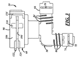
図面を参照すると、図1から図5は、SCR排気処理システムのアセンブリ12において使用される、センサマニホールドとも呼ばれる自動車選択的接触還元(SCR)システムのセンサ保持部10の実施形態を示す。センサ保持部10は、迅速接続機能を有し得て、これにより、尿素品質センサなどのセンサ14がより容易にセンサ保持部内に挿入されてそこで保持され得るとともに、点検および交換のためにセンサ保持部から解除されて取り外され得る。センサ保持部10は、SCRシステムのタンクの下流かつSCRシステムの投与注入部の上流のSCRシステムのアセンブリ12において直列に(供給ラインまたは戻りライン)に置かれ、これによってSCRシステムのアセンブリにおける改造が容易となり得て、SCRシステムのタンクにおける既知の設置方法と比較して複雑さが低減され得る。寒冷気候における使用のために、保持部を通過する尿素などの還元剤に熱を放射するためにセンサ保持部10の周りに1つ以上の抵抗線が配置され得る。尿素を還元剤とし、尿素品質センサを有するものとして記載されているが、センサ保持部10は他の還元剤および他のタイプのセンサとともに使用され得る。
Detailed Description of the Preferred Embodiments Referring to the drawings, FIGS. 1-5 show a
SCRシステムのアセンブリ12は、尿素タンクと尿素投与注入部との間の少なくとも途中において、加圧尿素流体を運ぶ。SCRシステムのアセンブリ12は、他の考えられるものの中から車両における特定の用途に応じて、異なる設計、構成、および構成部品を有し得る。図1の実施形態において、たとえば、SCRシステムのアセンブリ12は、センサ保持部10と、第1のSCRライン16と、入口接続部18と、第2のSCRライン20と、出口接続部22と、カバー24とを含む。第1のSCRライン16、または尿素ラインは、尿素タンクからセンサ保持部10へ尿素流体を運ぶ。センサ保持部10とは反対側の端部において、第1のSCRライン16は、尿素タンクへの接続を容易にするために結合部に嵌合され得る。軸方向および長手方向の範囲に沿って、第1のSCRライン16は、そこを通過する尿素流体に対して抵抗加熱によって熱を放出するために、その外表面に巻かれた、またはそれ以外の方法で外表面に配置される1つ以上の抵抗線を有し得る。終端26において、第1のSCRライン16は、入口接続部18に接続される。さらに図1を参照すると、入口接続部18は、第1のSCRライン16とセンサ保持部10との間の液密接続を容易にする。第1のSCRライン16は、第1の端部28にしっかりと挿入され(たとえば、圧入)、入口接続部18の第2の端部30は、センサ保持部10に挿入される。第2の端部30は、勾配部分を有し得て、封止のためにガスケット32が設けられ得る。第1のSCRライン16からセンサ保持部10へ尿素流体を運ぶために、通路34が第1および第2の端部28,30の間に延在する。さらに、入口接続部18は、1つ以上の任意の抵抗線の配置を支持するために外表面から延在する1つ以上のリブ36を有し得て、入口接続部は、以下に記載のように入口リテーナの挿入を受けるために第1の溝38と第2の溝40とを有し得る。
The SCR system assembly 12 carries pressurized urea fluid at least halfway between the urea tank and the urea dosing inlet. The SCR system assembly 12 may have different designs, configurations, and components, depending on the particular application in the vehicle, among other possible ones. In the embodiment of FIG. 1, for example, the SCR system assembly 12 includes a
同様に、第2のSCRライン20または尿素ラインは、センサ保持部10から投与注入部へ尿素流体を運ぶ。センサ保持部10とは反対側の端部において、第2のSCRライン20は、投与注入部への接続を容易にするために結合部と嵌合され得る。軸方向および長手方向の範囲に沿って、第2のSCRライン20は、そこを通過する尿素流体に対する抵抗加熱によって熱を放出するために、その外表面に巻かれる、または他の方法によって配置される1つ以上の抵抗線を有し得る。終端42において、第2のSCRライン20は、出口接続部22に接続される。出口接続部22は、第2のSCRライン20とセンサ保持部10との間の液密接続を容易にする。第2のSCRライン20は、第1の端部44にしっかりと挿入され(たとえば、圧入)、出口接続部22の第2の端部46は、センサ保持部10に挿入される。第2の端部46は、勾配部分を有し得て、ガスケット48が封止のために設けられ得る。センサ保持部10から第2のSCRライン20へ尿素流体を運ぶために、通路50は、第1および第2の端部44,46の間に延在する。さらに、出口接続部22は、1つ以上の任意の抵抗線の配置を支持するために外表面から延在する1つ以上のリブ52を有し得て、出口接続部は、以下に記載のように出口リテーナの挿入を受けるために第1の溝54と第2の溝56とを有し得る。また、さらに図1を参照すると、カバー24は、センサ保持部10の一部、入口接続部18の全体、および出口接続部22の全体を囲って保護する。また、カバー24は、第1のSCRライン16の終端26および第2のSCRライン20の終端42を囲って保護する。柔軟性のために、カバー24は、ゴムまたは他の柔軟な材料からなり得る。
Similarly, the
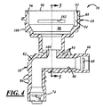
SCRシステムのセンサ保持部10は、第1および第2のSCRライン16,20と接続し、センサ保持部ならびに第1および第2のSCRラインの間を通過する尿素流体の品質を測定する位置に尿素品質センサ14を保持する。センサ保持部10は、他の考えられるものの中で、SCRシステムアセンブリ12における位置ならびにセンサ14のタイプおよび構成に応じて、異なる設計、構成、および構成部品を有し得る。図1から図5の実施形態において、センサ保持部10は、PA12 GF50などのプラスチック材料から一体的になり、センサ保持部は、管58と、チャンバ60と、リテーナ62と、1つ以上の抵抗線64とを含む。図2から図4を参照すると、管58は、入口接続部18の挿入を受け、入口接続部の勾配部分に対応する径方向に減少した部分を有する入口66を有する。入口66は、入口リテーナ72の一部を受けるために、特に入口リテーナの第1および第2の脚部をそれぞれ受けるために、その壁に規定される第1の開口68と第2の開口70とを有する。ひとたび第1および第2の開口68,70を通って移動すると、第1および第2の脚部は、それぞれ入口接続部18の第1および第2の溝38,40にそれぞれ受けられる。脚部、開口68および70、溝38および40、ならびにこれらの相互作用により、センサ保持部10と入口接続部18との間に迅速接続機能が付与される。より永続的な接続のために、脚部、開口68および70、ならびに溝38および40において入口66に対して成形材料が被せられ得る。
The
同様に、管58は、出口接続部22の挿入を受け、出口接続部の勾配部分に対応するように径方向に減少した部分を有する出口74を有する。出口74は、出口リテーナ79の一部を受けるために、特に出口リテーナの第1および第2の脚部をそれぞれ受けるためにその壁に規定される第1の開口76と第2の開口78とを有する。ひとたび第1および第2の開口76,78を通って移動すると、第1および第2の脚部は、出口接続部22の第1および第2の溝54,56においてそれぞれ受けられる。脚部、開口76および78、溝54および56、ならびにこれらの相互作用により、センサ保持部10と出口接続部22との間に迅速接続機能が付与される。より永続的な接続のために、脚部、開口76および78、ならびに溝54および56において出口74に成形材料が被せられ得る。
Similarly, the
図1および図4を参照すると、管58の通路80は、入口66と出口74との間を延在し、その間で尿素流体を運ぶ。通路80は、入口および出口接続部18,22の通路34,50と直接的に流体連通する。図1に示されるように、通路80は、チャンバ60に対して開かれてアクセス可能であり、尿素品質センサ14の測定先端部は、尿素流体の特性を測定または感知するために、通過する尿素流体内に垂下または導入され得る。図面の実施形態において、管58は、長手方向の範囲において形成されるほぼ垂直な湾曲部82を有する。湾曲部82は、通路80がチャンバ60に対して開かれる位置の下流に配置される。ここで図1から図4を参照すると、管58は、抵抗線64の配置を支持するために第1のリブ84と第2のリブ86とを有し得る。第1のリブ84は、入口66に隣接する管58の外表面の周りを周方向に延在する連続的ならせん状の延在部であり得る、または他の構造および配置を有し得る。同様に、第2のリブ86は、出口74に隣接する管58の外表面の周りを周方向に延在する連続的ならせん状の延在部であり得る、または他の構造および配置を有し得る。
With reference to FIGS. 1 and 4, the
チャンバ60は、尿素品質センサ14の挿入を受ける。チャンバ60は、考えられる他のものの中で、センサ14のタイプおよび構造に応じて、異なる設計、構成、および構成部品を有し得る。図1から図5の実施形態において、チャンバ60は、内部90を規定するチャンバ壁88を有する。内部90は、尿素品質センサ14の挿入に適合し、センサの形状に対応する空間を提供し、これによって異なるセンサのための異なる空間および形状が提供され得る。チャンバ壁88は、尿素品質センサ14を適切に収容するための一連の径方向に減少した部分を有する内表面92を有する。チャンバ60における尿素品質センサのガイドおよび案内を補助するために、第1および第2のスロット94,96が内表面92に設けられ、センサの対応する部分または構造を受ける。チャンバ60は、開上部98と、尿素品質センサ14の測定先端部が垂下し、通過する尿素流体内へ導入することができるように管58の通路80に対して開かれてアクセス可能な開底部100とを有する(図1に示される)。さらに、第1および第2の開口102,104がチャンバ壁88に規定され、チャンバ壁を完全に貫通して内部90へ導かれる。第1および第2の開口102,104は、リテーナ62と相互作用し、以下により詳細に記載されるように、センサ保持部10と尿素品質センサ14との間に迅速接続機能を付与する。また、外表面106において、第1および第2の凹部108,110がリテーナ62における収容のために設けられ、第1および第2のカバー112,114がリテーナの一部を隠すために設けられる。
リテーナ62は、チャンバ60と相互作用し、尿素品質センサ14がセンサ保持部10に容易に挿入されて保持され、その後に点検および交換のためにセンサ保持部を解除および取り外しできるように、迅速接続機能を付与する。リテーナ62は、チャンバ60の構成および設計、ならびにセンサ14のタイプおよび構成に応じて、考えられる他のものの中から異なる設計、構成、および構成部品を有することができる。図2の実施形態において、リテーナ62は、内方向に付勢され、第1の脚部116と、第2の脚部118と、これらの間に延在するブリッジ部120とを有する一体のステンレス鋼ばねである。第1および第2の脚部116,118は、形状およびサイズが実質的に同様であり得る。使用時の第1の位置において、リテーナ62は幾分緩くチャンバ60によって担持され、第1の脚部116の端部は第1の凹部108に収容され、第2の脚部118の端部は第2の凹部110に収容される(図2において破線で示される)。ここで、ブリッジ部120は、外部からユーザによって点検可能かつアクセス可能であり、第1および第2の脚部116,118は、内部90の外側かつ第1および第2の開口102,104の外側に配置される。
The retainer 62 interacts with the
第2の位置に持ってくるために、ブリッジ120は、内部90の方向、および一対のフランジ122,124の間でブリッジが当接することのできる外表面106の方向へ移動され得る。フランジ122,124は、リテーナ62が第2の位置にある時にブリッジ120が不意に外れないように補助する。同時に、第1および第2の脚部116,118は、内部90へ向けて移動され、脚部が移動して摺動するにつれて外表面106に重みを加える。第1および第2の脚部116,118は、それぞれ第1および第2の開口102,104を通って内部90に移動する(図2において実線で示される)。ここで第1および第2の脚部116,118の端部は、それぞれ概ね第1および第2のカバー112の下方に配置される。脚部116,118および開口102,104は、迅速接続機能をもたらす。たとえば、尿素品質センサ14をセンサ保持部10へ挿入するために、リテーナ62が第1の位置に持ってこられ、センサがチャンバ60の内側に配置され得る。尿素品質センサ14をチャンバ60内に保持するために、リテーナ62が第2の位置に持ってこられ、第1および第2の脚部116,118が、第1および第2の開口102,104を通り、凹部へ移動する、またはセンサのエッジ部に対して移動する。尿素品質センサ14は、これによってセンサ保持部10内に固定され、チャンバ60の離脱が防止される。リテーナ62とは別に他の接続技術が必要とならないように、尿素品質センサ14とチャンバ60との間で1つ以上のガスケットによる締まり嵌めが行なわれ得る。逆に、センサ保持部10から尿素品質センサ14を解除するために、リテーナ62は第1の位置に戻され、センサがチャンバ60から取り外され得る。
To bring it to the second position, the
抵抗線64は、抵抗加熱によって適切な量の熱を直接的に管58に放出し、管を通過する尿素流体に対して間接的に熱を放出する。熱は、管58を通る流れおよび尿素品質センサ14による感知のための適切な温度に尿素流体が確実に達するよう補助する。図1の実施形態において、抵抗線64は、管58の周り、ならびに第1および第2のリブ84,86の周りに巻かれる銅線であり得る。抵抗線64は、第1および第2のリブ84,86の周りに巻かれる単一の線であり得る、または第1および第2のリブの周りに巻かれる別個の異なる線であり得る。抵抗線64に電流を付与して熱を発生させるために、線は自動車制御ユニットなどの電子制御ユニット(ECU)または他の装置に対して電気的に結合され得る。抵抗線についてのこの記載は、上述の第1のSCRライン16の抵抗線、入口接続部18の抵抗線、第2のSCRライン20の抵抗線、および出口接続部22の抵抗線にも適用される。
The
図面に示されない他の実施形態において、SCRシステムのアセンブリ12およびSCRシステムのセンサ保持部10は、異なる設計、構成、および構成部品を有し得る。たとえば、センサ保持部の管は、湾曲部を有する必要はなく、代わりに一方向とすることができる、または合計で3つの入口および出口を有するT字形状を有し得る。抵抗線は、センサ保持部に設けられる必要はなく、熱放出機能は抵抗線以外の加熱要素によって付与され得る。チャンバとリテーナとの間の迅速接続機能は、リテーナを伴わない方法を含む異なる方法で付与され得る。たとえば、バルブと係合する、またはバルブの凹部に受けられる、相互接続もしくは相互係合構造を伴う迅速接続、バルブの構造または一部を受けるように凹部を伴う迅速接続、またはスナップ嵌合動作もしくは捻り係止動作による相互係止を伴う迅速接続などがある。同様に、管の入口および出口ならびにそれぞれの入口接続部および出口接続部の間の迅速接続機能を付与する必要はなく、上に記載される方法など、他の方法によって付与されてもよい。
In other embodiments not shown in the drawings, the SCR system assembly 12 and the SCR
上述の記載は、本発明の1つ以上の好ましい例示的な実施形態についての記載であることが理解される。本発明は、本明細書に開示される特定の実施形態に限定されるものではなく、以下の請求項のみによって規定される。さらに、上述の記載に含まれる記述は、特定の実施形態に関連するものであって、発明の範囲に対する限定、または用語もしくは語句が明示的に上で規定される場合を除いて、請求項において使用される用語の定義に対する限定として解釈されるものではない。様々な他の実施形態、ならびに開示される実施形態に対する様々な変形および変更は、当業者にとって明らかなものとなる。全てのこのような他の実施形態、変形、および変更は、添付の請求項の範囲内に入ることが意図される。 It is understood that the above description is that of one or more preferred exemplary embodiments of the invention. The invention is not limited to the specific embodiments disclosed herein, but is defined only by the following claims. Further, the statements contained in the above description relate to the specific embodiments and are not intended to limit the scope of the invention or, unless the terms or phrases are explicitly defined above, in the claims. It is not to be construed as a limitation on the terms used. Various other embodiments and various variations and modifications to the disclosed embodiments will be apparent to those skilled in the art. All such other embodiments, variations and modifications are intended to fall within the scope of the appended claims.
本明細書および請求項において使用される、「たとえば(for example)」、「例として(for instance)」、「など(such as)」、および「のような(like)」という用語、「備える(comprising)」、「有する(having)」、および「含む(including)」という動詞、ならびにこれらの他の動詞の形態は、列挙される1つ以上の構成部品または他の物と併せて使用される場合、各々はオープンエンド形式として解釈され、これは列挙されたものが他の追加の構成部品または物を排除するものではないと考慮することを意味する。他の用語は、異なる解釈を必要とする文脈において使用されない限り、最も広い合理的な意味を用いて解釈される。 As used herein and in the claims, the terms “for example”, “for instance”, “such as”, and “like”, “comprising” The verbs “comprising”, “having”, and “including”, as well as other forms of these verbs, are used in conjunction with one or more of the listed components or others. Each is interpreted as an open-ended format, which means that what is listed does not exclude other additional components or objects. Other terms are to be construed using their broadest reasonable meaning unless used in a context that requires a different interpretation.
Claims (19)
第1のSCRラインから入る流体を受ける入口を有し、出る流体を第2のSCRラインへ導く出口を有し、前記入口と前記出口との間の通路を有する管と、
前記通路にアクセス可能な内部を有するチャンバとを備え、前記内部はSCRシステムのセンサを受け、前記チャンバは前記内部へ通じる開口を有し、前記保持部はさらに、
前記チャンバの前記開口において移動可能な部分を有するリテーナを備え、前記部分が前記開口内において前記内部へ向けて移動すると、前記部分は前記SCRシステムのセンサに当接し、前記SCRシステムのセンサを前記自動車SCRシステムのセンサ保持部内に保持し、前記部分が前記内部から離れる方向へ移動した場合、前記SCRシステムのセンサは前記自動車SCRシステムのセンサ保持部から解除することができる、保持部。 A sensor holding part of an automobile selective contact reduction (SCR) system, wherein the holding part is
A tube having an inlet for receiving fluid entering from the first SCR line, having an outlet for directing outgoing fluid to the second SCR line, and having a passage between the inlet and the outlet;
A chamber having an interior accessible to the passage, the interior receiving a sensor of an SCR system, the chamber having an opening leading to the interior, and the holding portion further comprising:
A retainer having a movable portion at the opening of the chamber, the portion abutting against a sensor of the SCR system when the portion moves inwardly within the opening; A holding part that is held in a sensor holding part of an automobile SCR system, and the sensor of the SCR system can be released from the sensor holding part of the automobile SCR system when the part moves away from the inside.
前記管の前記入口内に挿入される入口接続部と、
前記管の前記出口内に挿入される出口接続部と、
前記入口接続部に接続される第1のSCRラインと、
前記出口接続部に接続される第2のSCRラインとを備える、アセンブリ。 An assembly of an automotive selective catalytic reduction (SCR) system, the assembly comprising a holder that includes a tube, a chamber, and a heating element, the tube including an inlet, an outlet, the inlet and the outlet The chamber has an interior accessible to the passage, the interior receives an SCR system sensor, and the heating element emits heat to at least a portion of the tube And the assembly further includes
An inlet connection inserted into the inlet of the tube;
An outlet connection inserted into the outlet of the tube;
A first SCR line connected to the inlet connection;
A second SCR line connected to the outlet connection.
第1のSCRラインから入る流体を受ける入口を有し、出る流体を第2のSCRラインへ導く出口を有し、前記入口と前記出口との間の通路を有する管を備え、前記入口は、前記通路へ通じる第1の開口を有し、前記出口は前記通路へ通じる第2の開口を有し、前記保持部はさらに、
前記通路へアクセス可能な内部を有するチャンバを備え、前記内部はSCRシステムのセンサを受け、前記チャンバは、前記通路において前記SCRシステムのセンサの一部を受けるために前記管の前記通路に対して開かれた開底部を有し、前記チャンバは前記内部へ通じる第3の開口を有し、前記保持部はさらに、
前記管に熱を放出するために前記管の少なくとも一部の周りに配置される抵抗線と、
前記第1の開口内において移動可能な部分を有する第1のリテーナと、
前記第2の開口内において移動可能な部分を有する第2のリテーナと、
前記第3の開口内において移動可能な部分を有する第3のリテーナとを備える、センサ保持部。 A sensor holding part of an automobile selective contact reduction (SCR) system, wherein the holding part is
An inlet for receiving fluid entering from the first SCR line; an outlet for directing outgoing fluid to the second SCR line; and a tube having a passage between the inlet and the outlet, the inlet comprising: The outlet has a first opening leading to the passage; the outlet has a second opening leading to the passage;
A chamber having an interior accessible to the passage, wherein the interior receives a sensor of the SCR system and the chamber receives the portion of the sensor of the SCR system in the passage relative to the passage of the tube. An open bottom portion, the chamber has a third opening leading to the interior, and the holding portion further includes:
A resistance wire disposed around at least a portion of the tube to dissipate heat to the tube;
A first retainer having a portion movable within the first opening;
A second retainer having a portion movable within the second opening;
And a third retainer having a portion movable within the third opening.
Applications Claiming Priority (3)
| Application Number | Priority Date | Filing Date | Title |
|---|---|---|---|
| US201261604379P | 2012-02-28 | 2012-02-28 | |
| US61/604,379 | 2012-02-28 | ||
| PCT/US2013/028326 WO2013130810A1 (en) | 2012-02-28 | 2013-02-28 | Automotive selective catalytic reduction (scr) system sensor holder and assembly |
Publications (2)
| Publication Number | Publication Date |
|---|---|
| JP2015515567A JP2015515567A (en) | 2015-05-28 |
| JP6131277B2 true JP6131277B2 (en) | 2017-05-17 |
Family
ID=49001553
Family Applications (1)
| Application Number | Title | Priority Date | Filing Date |
|---|---|---|---|
| JP2014560040A Active JP6131277B2 (en) | 2012-02-28 | 2013-02-28 | Automotive selective contact reduction (SCR) system sensor holder and assembly |
Country Status (9)
| Country | Link |
|---|---|
| US (1) | US9388932B2 (en) |
| EP (2) | EP3203047B1 (en) |
| JP (1) | JP6131277B2 (en) |
| KR (1) | KR20140129176A (en) |
| CN (1) | CN104145095B (en) |
| BR (1) | BR112014021239A2 (en) |
| CA (1) | CA2865495C (en) |
| MX (1) | MX353573B (en) |
| WO (1) | WO2013130810A1 (en) |
Families Citing this family (16)
| Publication number | Priority date | Publication date | Assignee | Title |
|---|---|---|---|---|
| EP2846014B1 (en) * | 2013-09-10 | 2017-03-15 | Inergy Automotive Systems Research (Société Anonyme) | Module for an SCR system and system comprising same. |
| CN104948271B (en) * | 2014-03-25 | 2017-12-08 | 浙江福爱电子有限公司 | A kind of SCR injection metering modules and control method |
| DE102014005817A1 (en) | 2014-04-24 | 2015-10-29 | Voss Automotive Gmbh | Multi-part heatable media line, line connection device for such and method for producing such |
| US10012121B2 (en) * | 2014-05-20 | 2018-07-03 | Ssi Technologies, Inc. | Reduction of aeration interference via tortuous path and sensor boot |
| EP3150813A1 (en) * | 2015-09-30 | 2017-04-05 | Plastic Omnium Advanced Innovation and Research | Feed line system for a vehicle system |
| JP6563854B2 (en) * | 2016-05-20 | 2019-08-21 | 株式会社ニフコ | Locking mechanism of tubular body |
| US10396500B2 (en) | 2016-08-31 | 2019-08-27 | Norma U.S. Holding Llc | Electrically conductive conduit assembly |
| GB2559998B (en) * | 2017-02-24 | 2019-05-08 | Pipe Transf Ltd | Pipeline apparatus with releasably lockable device |
| EP3369901B1 (en) * | 2017-03-03 | 2019-10-16 | MEAS France | Urea sensor protection assembly and urea sensor system |
| EP3382254B1 (en) * | 2017-03-29 | 2020-06-03 | TI Automotive (Fuldabrück) GmbH | Heated pipeline with plug, and a method for operating this pipeline |
| NO20171589A1 (en) | 2017-10-05 | 2019-02-18 | Sentec As | Level sensor assembly |
| US10590825B2 (en) * | 2017-11-27 | 2020-03-17 | Voss Automotive Gmbh | Line connector with integrated sensor for measurement of urea solutions |
| US10508577B2 (en) * | 2017-11-27 | 2019-12-17 | Voss Automotive Gmbh | Line connector with integrated sensor for measurement of urea solutions |
| DE102017127936A1 (en) * | 2017-11-27 | 2019-05-29 | Voss Automotive Gmbh | Cable connector with integrated sensor for measuring urea solutions |
| CN109488870B (en) * | 2018-12-17 | 2021-02-05 | 宁波世峻汽配科技有限公司 | Engine oil cooling pipe |
| MX2023003351A (en) * | 2020-09-25 | 2023-03-29 | Parker Hannifin Corp | Freeze resistant quick connect fitting. |
Family Cites Families (64)
| Publication number | Priority date | Publication date | Assignee | Title |
|---|---|---|---|---|
| DE8704903U1 (en) | 1987-04-02 | 1987-05-27 | Rehau Ag + Co, 8673 Rehau, De | |
| FR2637021B1 (en) | 1988-09-23 | 1993-12-03 | Peugeot Automobiles | DEVICE FOR REGULATING THE FUEL PRESSURE OF AN INJECTION ENGINE HAVING A GREAT EASE OF ASSEMBLY AND DISASSEMBLY |
| US5000614A (en) * | 1989-05-05 | 1991-03-19 | Huron Products Corporation | Conduit quick connector assembly having a ramped housing with a hair pin retainer |
| JPH0875585A (en) | 1994-09-09 | 1996-03-22 | Smc Corp | Connection structure of pressure detector |
| JPH08219352A (en) | 1995-02-09 | 1996-08-30 | Toto Ltd | Pipe joint |
| US5869766A (en) * | 1995-10-03 | 1999-02-09 | Nt International, Inc. | Non-contaminating pressure transducer module |
| US5693887A (en) | 1995-10-03 | 1997-12-02 | Nt International, Inc. | Pressure sensor module having non-contaminating body and isolation member |
| DE19653405C2 (en) * | 1996-12-20 | 1999-06-10 | Bosch Gmbh Robert | Mixture dispenser |
| US5976475A (en) * | 1997-04-02 | 1999-11-02 | Clean Diesel Technologies, Inc. | Reducing NOx emissions from an engine by temperature-controlled urea injection for selective catalytic reduction |
| JP3202942B2 (en) | 1997-07-15 | 2001-08-27 | トヨタ自動車株式会社 | Fluid sensor |
| JP3708691B2 (en) | 1997-10-17 | 2005-10-19 | シーケーディ株式会社 | Pressure detector |
| JPH11325361A (en) * | 1998-05-19 | 1999-11-26 | Togo Seisakusyo Corp | Structure for confirming pipe assembly state in connector |
| DE19902431B4 (en) | 1999-01-22 | 2006-04-27 | Siemens Ag | Intermediate piece with a connection of washing liquid lines of a window cleaning system |
| US6343814B1 (en) | 1999-11-08 | 2002-02-05 | Ti Group Automotive Systems, Llc | Insertion verifier dust cap |
| JP3981224B2 (en) | 1999-11-19 | 2007-09-26 | 東海ゴム工業株式会社 | Connector and resin tube connection structure using the same |
| US6363771B1 (en) * | 1999-11-24 | 2002-04-02 | Caterpillar Inc. | Emissions diagnostic system |
| DE19961287A1 (en) * | 1999-12-18 | 2001-06-21 | Bosch Gmbh Robert | Motor vehicle fuel system connection comprises sleeve with stepped bore to take sensor held in by mutually offset corrugated legs of stirrup link. |
| JP3600509B2 (en) * | 2000-06-23 | 2004-12-15 | トヨタ自動車株式会社 | Exhaust gas purification device for internal combustion engine |
| DE10032616A1 (en) | 2000-07-08 | 2002-01-24 | Mhm Harzbecher Medizintechnik | System element for transducer connection in pressure-monitoring sets for extracorporeal circuits, e.g. in open-heart surgery, has a measuring chamber with a membrane which fits in a special channel in the housing |
| JP4447142B2 (en) * | 2000-10-06 | 2010-04-07 | トヨタ自動車株式会社 | Exhaust gas purification device for internal combustion engine |
| AU2002228232B2 (en) | 2001-02-06 | 2006-10-05 | Elster Metering Limited | Flowmeter |
| DE10115322A1 (en) * | 2001-03-28 | 2002-10-17 | Bosch Gmbh Robert | Fuel injection device for internal combustion engines, in particular common rail injector |
| JP4291989B2 (en) * | 2002-10-01 | 2009-07-08 | 株式会社パイオラックス | Piping connector |
| DE10255267A1 (en) | 2002-11-21 | 2004-06-03 | Behr Thermot-Tronik Gmbh | Car air conditioning temperature sensor unit, has sensor mount in special pipe fitting with bore for sensor housing and blind recess for sensor |
| DE10259395A1 (en) | 2002-12-19 | 2004-07-22 | Festo Ag & Co. | Connector for fluid lines |
| DE10322124A1 (en) | 2003-05-16 | 2004-12-02 | Robert Bosch Gmbh | Device for determining at least one parameter of a medium flowing in a line |
| KR20070006673A (en) | 2003-10-20 | 2007-01-11 | 인터내셔널 레지스티브 캄퍼니, 인크. | Resistive film on aluminum tube |
| US7341097B2 (en) | 2003-11-03 | 2008-03-11 | Chrysler Llc | Coolant sensor and bleed valve |
| JP4529658B2 (en) | 2003-11-28 | 2010-08-25 | 東海ゴム工業株式会社 | Quick connector |
| FR2864700A1 (en) | 2003-12-31 | 2005-07-01 | Siemens Vdo Automotive | Covering procedure for electronic sensor, e.g. for motor vehicle, consists of attaching cable to first part of housing and then overmoulding with remainder |
| JP2005227027A (en) | 2004-02-10 | 2005-08-25 | Denso Corp | Temperature sensor and temperature sensor housing mechanism |
| JP2006183764A (en) | 2004-12-27 | 2006-07-13 | Onda Seisakusho Seki Kojo:Kk | Joint |
| WO2006087541A1 (en) * | 2005-02-16 | 2006-08-24 | Imi Vision Limited | Exhaust gas treatment |
| US7438328B2 (en) | 2005-03-25 | 2008-10-21 | Tokai Rubber Industries, Ltd. | Quick connector |
| EP1710484B1 (en) | 2005-04-05 | 2009-06-17 | DBK David + Baader GmbH | Electrical heater for a fluid in a flexible hose |
| DE202006003590U1 (en) | 2005-04-14 | 2006-06-01 | Schlemmer Gmbh | Heatable corrugated hose for motor vehicles has crests and gaps to produce sequence of gaps, which is extended spirally over the length of corrugated hose forming a corrugation, within which heating element can be inserted |
| US20060251548A1 (en) * | 2005-05-06 | 2006-11-09 | Willey Ray L | Exhaust aftertreatment device |
| US7466147B2 (en) | 2005-08-08 | 2008-12-16 | Continental Automotive Systems Us, Inc. | Fluid quality sensor |
| JP4957081B2 (en) | 2005-09-15 | 2012-06-20 | 株式会社デンソー | Flow measuring device |
| US7325463B2 (en) | 2005-09-16 | 2008-02-05 | Bendix Commercial Vehicle Systems, Llc | Fluid sensor assembly |
| EP1931906A1 (en) | 2005-09-16 | 2008-06-18 | Dayco Fluid Technologies S.p.A. | Pipe fitting for a heatable piping of a scr system |
| SE529417C2 (en) | 2005-12-22 | 2007-08-07 | Volvo Lastvagnar Ab | Wiring harness for a vehicle |
| US20070187869A1 (en) * | 2006-02-15 | 2007-08-16 | Siemens Vdo Automotive Corporation | Single mold active speed sensor |
| FR2905161B1 (en) | 2006-08-25 | 2012-04-20 | Inergy Automotive Systems Res | CONNECTION WITH INTEGRATED HEATING ELEMENT. |
| EP2095085B1 (en) | 2006-12-11 | 2017-02-22 | Kistler Holding AG | Adapter for pressure sensors |
| DE102008006323B4 (en) | 2007-02-27 | 2014-04-30 | Eichenauer Heizelemente Gmbh & Co. Kg | Reductant supply system for an exhaust gas purification catalyst of an internal combustion engine and plug connection for connecting heated liquid lines |
| SE0700478L (en) | 2007-02-27 | 2008-08-28 | Promech Lab Ab | Apparatus and method for detecting particles in a particulate flow |
| JP4710868B2 (en) | 2007-04-25 | 2011-06-29 | トヨタ自動車株式会社 | Exhaust gas purification device for internal combustion engine |
| WO2008131993A1 (en) | 2007-04-26 | 2008-11-06 | Voss Automotive Gmbh | Line connector for media lines |
| DE202007009588U1 (en) * | 2007-04-26 | 2008-09-04 | Voss Automotive Gmbh | Cable connector for media cables |
| ATE533989T1 (en) | 2007-04-26 | 2011-12-15 | Voss Automotive Gmbh | LINE CONNECTOR FOR MEDIA LINES |
| US7699356B2 (en) | 2007-05-10 | 2010-04-20 | Craig Assgembly, Inc. | Quick connector for fluid conduit |
| DE102007027413B4 (en) * | 2007-06-11 | 2016-10-20 | Eichenauer Heizelemente Gmbh & Co. Kg | Reducing agent supply system for an exhaust gas purification catalyst of an internal combustion engine |
| PL2222995T3 (en) | 2007-12-21 | 2015-04-30 | Voss Automotive Gmbh | Line connector for media lines and ready-made media line with at least one such line connector |
| DE202007018089U1 (en) | 2007-12-21 | 2009-05-07 | Voss Automotive Gmbh | Heatable media line |
| IT1391189B1 (en) | 2008-08-01 | 2011-11-18 | Eltek Spa | FLOW METER |
| DE202009012230U1 (en) | 2009-06-23 | 2010-11-04 | Voss Automotive Gmbh | Electrically heatable media cable and cable connectors |
| IT1396306B1 (en) * | 2009-11-06 | 2012-11-16 | Eltek Spa | ELECTRIC HEATER, HEATING DEVICE AND HEATING SYSTEM. |
| US8002315B2 (en) | 2009-12-23 | 2011-08-23 | General Electric Corporation | Device for measuring fluid properties in caustic environments |
| DE102009060363A1 (en) * | 2009-12-24 | 2011-06-30 | Volkswagen AG, 38440 | connecting unit |
| DE102010061271A1 (en) | 2010-12-15 | 2012-06-21 | Contitech Schlauch Gmbh | Heatable connection device for media-carrying, electrically heatable hoses |
| US20130213013A1 (en) * | 2011-01-14 | 2013-08-22 | Cummins Ip, Inc. | Exhaust gas sensor module |
| EP2767819A4 (en) * | 2011-10-12 | 2015-09-16 | Horiba Ltd | Gas analysis apparatus |
| EP2684597A1 (en) * | 2012-07-14 | 2014-01-15 | Deutz AG | Method for reducing nitrogen oxides in diesel engine exhaust |
-
2013
- 2013-02-28 CN CN201380011482.4A patent/CN104145095B/en not_active Expired - Fee Related
- 2013-02-28 BR BR112014021239-2A patent/BR112014021239A2/en not_active Application Discontinuation
- 2013-02-28 KR KR20147025659A patent/KR20140129176A/en not_active Application Discontinuation
- 2013-02-28 WO PCT/US2013/028326 patent/WO2013130810A1/en active Application Filing
- 2013-02-28 MX MX2014010276A patent/MX353573B/en active IP Right Grant
- 2013-02-28 EP EP17162739.1A patent/EP3203047B1/en not_active Revoked
- 2013-02-28 US US13/780,924 patent/US9388932B2/en active Active
- 2013-02-28 EP EP13754763.4A patent/EP2820259B1/en not_active Not-in-force
- 2013-02-28 JP JP2014560040A patent/JP6131277B2/en active Active
- 2013-02-28 CA CA2865495A patent/CA2865495C/en not_active Expired - Fee Related
Also Published As
| Publication number | Publication date |
|---|---|
| WO2013130810A1 (en) | 2013-09-06 |
| MX353573B (en) | 2018-01-18 |
| CN104145095B (en) | 2017-09-12 |
| EP3203047B1 (en) | 2018-10-17 |
| EP3203047A1 (en) | 2017-08-09 |
| EP2820259B1 (en) | 2017-05-31 |
| US9388932B2 (en) | 2016-07-12 |
| MX2014010276A (en) | 2015-05-08 |
| CN104145095A (en) | 2014-11-12 |
| JP2015515567A (en) | 2015-05-28 |
| BR112014021239A2 (en) | 2020-06-23 |
| KR20140129176A (en) | 2014-11-06 |
| EP2820259A1 (en) | 2015-01-07 |
| EP2820259A4 (en) | 2016-03-02 |
| US20130220467A1 (en) | 2013-08-29 |
| CA2865495A1 (en) | 2013-09-06 |
| CA2865495C (en) | 2019-06-11 |
Similar Documents
| Publication | Publication Date | Title |
|---|---|---|
| JP6131277B2 (en) | Automotive selective contact reduction (SCR) system sensor holder and assembly | |
| US7857645B2 (en) | Connector arrangement for a medium-conducting, electrically-heatable hose | |
| US8322134B2 (en) | Sliding fit, pipe arrangement and exhaust gas treatment device | |
| US10851932B2 (en) | Connection unit | |
| CN102713229B (en) | Intake manifold section and intake system | |
| US20160208751A9 (en) | Motor Vehicle Assembly Unit and Method for the Production of the Motor Vehicle Assembly Unit | |
| US9410471B2 (en) | Exhaust system component | |
| CN111226069B (en) | Connector for a heatable fluid line, in particular for an SCR system or a water injection system | |
| CN111033105A (en) | Connector with a locking member | |
| JP6238587B2 (en) | Coking-resistant post-treatment administration valve and manufacturing method | |
| CN107965376B (en) | Exhaust system with differential pressure sensor | |
| CN108104906B (en) | Exhaust gas treatment device | |
| CN116252749A (en) | Fluid connector assembly for a windshield wiper assembly | |
| CN114846262B (en) | Heat-insulating exhaust pipeline system | |
| WO2020234739A1 (en) | System for hydraulically and electrically connecting a plurality of hated ducts configured for carrying an electrically heatable fluid | |
| US20200063907A1 (en) | Plug Connector | |
| GB2619833A (en) | Insulated exhaust gas conduit systems | |
| KR101675461B1 (en) | Multi-filtering apparatus of engine-exhaust gas for agricultural machinery | |
| US20180306090A1 (en) | Outer beaded body for mounting and joint interfaces | |
| JP2016176389A (en) | Connector assembly and hose assembly |
Legal Events
| Date | Code | Title | Description |
|---|---|---|---|
| RD02 | Notification of acceptance of power of attorney |
Free format text: JAPANESE INTERMEDIATE CODE: A7422 Effective date: 20151126 |
|
| RD04 | Notification of resignation of power of attorney |
Free format text: JAPANESE INTERMEDIATE CODE: A7424 Effective date: 20151202 |
|
| A521 | Request for written amendment filed |
Free format text: JAPANESE INTERMEDIATE CODE: A821 Effective date: 20151126 |
|
| A621 | Written request for application examination |
Free format text: JAPANESE INTERMEDIATE CODE: A621 Effective date: 20160105 |
|
| A977 | Report on retrieval |
Free format text: JAPANESE INTERMEDIATE CODE: A971007 Effective date: 20161026 |
|
| A131 | Notification of reasons for refusal |
Free format text: JAPANESE INTERMEDIATE CODE: A131 Effective date: 20161108 |
|
| A521 | Request for written amendment filed |
Free format text: JAPANESE INTERMEDIATE CODE: A523 Effective date: 20170120 |
|
| TRDD | Decision of grant or rejection written | ||
| A01 | Written decision to grant a patent or to grant a registration (utility model) |
Free format text: JAPANESE INTERMEDIATE CODE: A01 Effective date: 20170404 |
|
| A61 | First payment of annual fees (during grant procedure) |
Free format text: JAPANESE INTERMEDIATE CODE: A61 Effective date: 20170417 |
|
| R150 | Certificate of patent or registration of utility model |
Ref document number: 6131277 Country of ref document: JP Free format text: JAPANESE INTERMEDIATE CODE: R150 |
|
| R250 | Receipt of annual fees |
Free format text: JAPANESE INTERMEDIATE CODE: R250 |
|
| R250 | Receipt of annual fees |
Free format text: JAPANESE INTERMEDIATE CODE: R250 |
|
| R250 | Receipt of annual fees |
Free format text: JAPANESE INTERMEDIATE CODE: R250 |
|
| R250 | Receipt of annual fees |
Free format text: JAPANESE INTERMEDIATE CODE: R250 |