EP2846014B1 - Module for an SCR system and system comprising same. - Google Patents
Module for an SCR system and system comprising same. Download PDFInfo
- Publication number
- EP2846014B1 EP2846014B1 EP13183685.0A EP13183685A EP2846014B1 EP 2846014 B1 EP2846014 B1 EP 2846014B1 EP 13183685 A EP13183685 A EP 13183685A EP 2846014 B1 EP2846014 B1 EP 2846014B1
- Authority
- EP
- European Patent Office
- Prior art keywords
- module
- sensor
- temperature
- socket
- electrical interface
- Prior art date
- Legal status (The legal status is an assumption and is not a legal conclusion. Google has not performed a legal analysis and makes no representation as to the accuracy of the status listed.)
- Active
Links
- XSQUKJJJFZCRTK-UHFFFAOYSA-N Urea Chemical compound NC(N)=O XSQUKJJJFZCRTK-UHFFFAOYSA-N 0.000 claims description 13
- 239000004202 carbamide Substances 0.000 claims description 13
- 238000000034 method Methods 0.000 claims description 4
- 238000000465 moulding Methods 0.000 claims description 4
- 238000004519 manufacturing process Methods 0.000 claims description 2
- 239000000654 additive Substances 0.000 description 3
- 230000000996 additive effect Effects 0.000 description 3
- 238000002485 combustion reaction Methods 0.000 description 3
- 239000007789 gas Substances 0.000 description 3
- 238000012986 modification Methods 0.000 description 3
- 230000004048 modification Effects 0.000 description 3
- 238000013461 design Methods 0.000 description 2
- 230000000694 effects Effects 0.000 description 2
- 239000012530 fluid Substances 0.000 description 2
- 238000002347 injection Methods 0.000 description 2
- 239000007924 injection Substances 0.000 description 2
- 238000010531 catalytic reduction reaction Methods 0.000 description 1
- 238000004891 communication Methods 0.000 description 1
- 239000007788 liquid Substances 0.000 description 1
- 238000005259 measurement Methods 0.000 description 1
- 239000000243 solution Substances 0.000 description 1
Images

Classifications
-
- F—MECHANICAL ENGINEERING; LIGHTING; HEATING; WEAPONS; BLASTING
- F01—MACHINES OR ENGINES IN GENERAL; ENGINE PLANTS IN GENERAL; STEAM ENGINES
- F01N—GAS-FLOW SILENCERS OR EXHAUST APPARATUS FOR MACHINES OR ENGINES IN GENERAL; GAS-FLOW SILENCERS OR EXHAUST APPARATUS FOR INTERNAL COMBUSTION ENGINES
- F01N11/00—Monitoring or diagnostic devices for exhaust-gas treatment apparatus, e.g. for catalytic activity
- F01N11/002—Monitoring or diagnostic devices for exhaust-gas treatment apparatus, e.g. for catalytic activity the diagnostic devices measuring or estimating temperature or pressure in, or downstream of the exhaust apparatus
-
- F—MECHANICAL ENGINEERING; LIGHTING; HEATING; WEAPONS; BLASTING
- F01—MACHINES OR ENGINES IN GENERAL; ENGINE PLANTS IN GENERAL; STEAM ENGINES
- F01N—GAS-FLOW SILENCERS OR EXHAUST APPARATUS FOR MACHINES OR ENGINES IN GENERAL; GAS-FLOW SILENCERS OR EXHAUST APPARATUS FOR INTERNAL COMBUSTION ENGINES
- F01N3/00—Exhaust or silencing apparatus having means for purifying, rendering innocuous, or otherwise treating exhaust
- F01N3/08—Exhaust or silencing apparatus having means for purifying, rendering innocuous, or otherwise treating exhaust for rendering innocuous
- F01N3/10—Exhaust or silencing apparatus having means for purifying, rendering innocuous, or otherwise treating exhaust for rendering innocuous by thermal or catalytic conversion of noxious components of exhaust
- F01N3/18—Exhaust or silencing apparatus having means for purifying, rendering innocuous, or otherwise treating exhaust for rendering innocuous by thermal or catalytic conversion of noxious components of exhaust characterised by methods of operation; Control
- F01N3/20—Exhaust or silencing apparatus having means for purifying, rendering innocuous, or otherwise treating exhaust for rendering innocuous by thermal or catalytic conversion of noxious components of exhaust characterised by methods of operation; Control specially adapted for catalytic conversion ; Methods of operation or control of catalytic converters
- F01N3/2066—Selective catalytic reduction [SCR]
-
- F—MECHANICAL ENGINEERING; LIGHTING; HEATING; WEAPONS; BLASTING
- F01—MACHINES OR ENGINES IN GENERAL; ENGINE PLANTS IN GENERAL; STEAM ENGINES
- F01N—GAS-FLOW SILENCERS OR EXHAUST APPARATUS FOR MACHINES OR ENGINES IN GENERAL; GAS-FLOW SILENCERS OR EXHAUST APPARATUS FOR INTERNAL COMBUSTION ENGINES
- F01N3/00—Exhaust or silencing apparatus having means for purifying, rendering innocuous, or otherwise treating exhaust
- F01N3/08—Exhaust or silencing apparatus having means for purifying, rendering innocuous, or otherwise treating exhaust for rendering innocuous
- F01N3/10—Exhaust or silencing apparatus having means for purifying, rendering innocuous, or otherwise treating exhaust for rendering innocuous by thermal or catalytic conversion of noxious components of exhaust
- F01N3/24—Exhaust or silencing apparatus having means for purifying, rendering innocuous, or otherwise treating exhaust for rendering innocuous by thermal or catalytic conversion of noxious components of exhaust characterised by constructional aspects of converting apparatus
- F01N3/28—Construction of catalytic reactors
- F01N3/2896—Liquid catalyst carrier
-
- F—MECHANICAL ENGINEERING; LIGHTING; HEATING; WEAPONS; BLASTING
- F01—MACHINES OR ENGINES IN GENERAL; ENGINE PLANTS IN GENERAL; STEAM ENGINES
- F01N—GAS-FLOW SILENCERS OR EXHAUST APPARATUS FOR MACHINES OR ENGINES IN GENERAL; GAS-FLOW SILENCERS OR EXHAUST APPARATUS FOR INTERNAL COMBUSTION ENGINES
- F01N2530/00—Selection of materials for tubes, chambers or housings
- F01N2530/18—Plastics material, e.g. polyester resin
-
- F—MECHANICAL ENGINEERING; LIGHTING; HEATING; WEAPONS; BLASTING
- F01—MACHINES OR ENGINES IN GENERAL; ENGINE PLANTS IN GENERAL; STEAM ENGINES
- F01N—GAS-FLOW SILENCERS OR EXHAUST APPARATUS FOR MACHINES OR ENGINES IN GENERAL; GAS-FLOW SILENCERS OR EXHAUST APPARATUS FOR INTERNAL COMBUSTION ENGINES
- F01N2610/00—Adding substances to exhaust gases
- F01N2610/02—Adding substances to exhaust gases the substance being ammonia or urea
-
- F—MECHANICAL ENGINEERING; LIGHTING; HEATING; WEAPONS; BLASTING
- F01—MACHINES OR ENGINES IN GENERAL; ENGINE PLANTS IN GENERAL; STEAM ENGINES
- F01N—GAS-FLOW SILENCERS OR EXHAUST APPARATUS FOR MACHINES OR ENGINES IN GENERAL; GAS-FLOW SILENCERS OR EXHAUST APPARATUS FOR INTERNAL COMBUSTION ENGINES
- F01N2610/00—Adding substances to exhaust gases
- F01N2610/14—Arrangements for the supply of substances, e.g. conduits
- F01N2610/1406—Storage means for substances, e.g. tanks or reservoirs
-
- F—MECHANICAL ENGINEERING; LIGHTING; HEATING; WEAPONS; BLASTING
- F01—MACHINES OR ENGINES IN GENERAL; ENGINE PLANTS IN GENERAL; STEAM ENGINES
- F01N—GAS-FLOW SILENCERS OR EXHAUST APPARATUS FOR MACHINES OR ENGINES IN GENERAL; GAS-FLOW SILENCERS OR EXHAUST APPARATUS FOR INTERNAL COMBUSTION ENGINES
- F01N2610/00—Adding substances to exhaust gases
- F01N2610/14—Arrangements for the supply of substances, e.g. conduits
- F01N2610/148—Arrangement of sensors
-
- F—MECHANICAL ENGINEERING; LIGHTING; HEATING; WEAPONS; BLASTING
- F01—MACHINES OR ENGINES IN GENERAL; ENGINE PLANTS IN GENERAL; STEAM ENGINES
- F01N—GAS-FLOW SILENCERS OR EXHAUST APPARATUS FOR MACHINES OR ENGINES IN GENERAL; GAS-FLOW SILENCERS OR EXHAUST APPARATUS FOR INTERNAL COMBUSTION ENGINES
- F01N2900/00—Details of electrical control or of the monitoring of the exhaust gas treating apparatus
- F01N2900/06—Parameters used for exhaust control or diagnosing
- F01N2900/18—Parameters used for exhaust control or diagnosing said parameters being related to the system for adding a substance into the exhaust
- F01N2900/1806—Properties of reducing agent or dosing system
- F01N2900/1811—Temperature
-
- F—MECHANICAL ENGINEERING; LIGHTING; HEATING; WEAPONS; BLASTING
- F01—MACHINES OR ENGINES IN GENERAL; ENGINE PLANTS IN GENERAL; STEAM ENGINES
- F01N—GAS-FLOW SILENCERS OR EXHAUST APPARATUS FOR MACHINES OR ENGINES IN GENERAL; GAS-FLOW SILENCERS OR EXHAUST APPARATUS FOR INTERNAL COMBUSTION ENGINES
- F01N2900/00—Details of electrical control or of the monitoring of the exhaust gas treating apparatus
- F01N2900/06—Parameters used for exhaust control or diagnosing
- F01N2900/18—Parameters used for exhaust control or diagnosing said parameters being related to the system for adding a substance into the exhaust
- F01N2900/1806—Properties of reducing agent or dosing system
- F01N2900/1818—Concentration of the reducing agent
-
- Y—GENERAL TAGGING OF NEW TECHNOLOGICAL DEVELOPMENTS; GENERAL TAGGING OF CROSS-SECTIONAL TECHNOLOGIES SPANNING OVER SEVERAL SECTIONS OF THE IPC; TECHNICAL SUBJECTS COVERED BY FORMER USPC CROSS-REFERENCE ART COLLECTIONS [XRACs] AND DIGESTS
- Y02—TECHNOLOGIES OR APPLICATIONS FOR MITIGATION OR ADAPTATION AGAINST CLIMATE CHANGE
- Y02A—TECHNOLOGIES FOR ADAPTATION TO CLIMATE CHANGE
- Y02A50/00—TECHNOLOGIES FOR ADAPTATION TO CLIMATE CHANGE in human health protection, e.g. against extreme weather
- Y02A50/20—Air quality improvement or preservation, e.g. vehicle emission control or emission reduction by using catalytic converters
-
- Y—GENERAL TAGGING OF NEW TECHNOLOGICAL DEVELOPMENTS; GENERAL TAGGING OF CROSS-SECTIONAL TECHNOLOGIES SPANNING OVER SEVERAL SECTIONS OF THE IPC; TECHNICAL SUBJECTS COVERED BY FORMER USPC CROSS-REFERENCE ART COLLECTIONS [XRACs] AND DIGESTS
- Y02—TECHNOLOGIES OR APPLICATIONS FOR MITIGATION OR ADAPTATION AGAINST CLIMATE CHANGE
- Y02T—CLIMATE CHANGE MITIGATION TECHNOLOGIES RELATED TO TRANSPORTATION
- Y02T10/00—Road transport of goods or passengers
- Y02T10/10—Internal combustion engine [ICE] based vehicles
- Y02T10/12—Improving ICE efficiencies
Definitions
- the present invention pertains to systems for selective catalytic reduction of NO x in the exhaust gas of internal combustion engines.
- the present invention pertains to a module including sensors for assessing properties of the content of a urea tank (for example, temperature and/or quality) , as disclosed e.g. in EP 1752762A1 , EP 1681443A1 or WO 2012/080132 .
- a module for an SCR system having a base plate with a socket and a combined temperature and urea quality sensor mounted in the socket, the module further comprising an electrical interface connected to the combined temperature and urea quality sensor, wherein the electrical interface is also adapted to alternatively connect to a temperature sensor.
- Embodiments of the present invention are based on the insight of the inventor that while it may be possible to place a combined quality and temperature sensor on the base plate to save space, this would require a redesign of the entire module. In addition, the resulting module would be more expensive, regardless of whether the quality measurement function is actually desired by the end customer.
- the invention provides a module architecture that supports a combined quality and temperature sensor, which could be replaced by a temperature sensor depending on the requirements of the customer, without requiring substantive modifications. In some embodiments, minor modifications may be needed, as will be described in more detail below.
- an SCR system comprising a module as described above and an ECU, the electrical interface connecting the combined temperature and urea quality sensor to the ECU, wherein the ECU is configured to read out a signal received via the electrical interface as digital sensor data.
- the ECU is further configured to read out a signal received from the electrical interface as analog sensor data, when the signal originates from a temperature sensor.
- the SCR system may be equipped with a combined quality and temperature sensor, or a temperature sensor, depending on the requirements of the customer, without requiring modifications of the wiring or the ECU.
- a motor vehicle comprising the SCR system as described above.
- Figure 1 represents a base plate 110 of a delivery module for a vehicular fluid tank, in particular a urea solution tank of an SCR system.
- a delivery module for a vehicular fluid tank, in particular a urea solution tank of an SCR system.
- WO 2009/007405 in the name of the present applicant, for a detailed description of a known module. Fluid communication between the inside and the outside of the tank is achieved by means of tubes passing through the base plate 110 (not visible in the views reproduced here).
- the base plate 110 is sometimes referred to in the art as the "flange".
- the module may be attached to a tank wall by placing it over an opening provided for that purpose, and securing it.
- the module of Figure 1 integrates a combined quality and temperature sensor 101 , i.e. a quality sensor also capable of measuring temperature. This allows replacing the temperature sensor of current designs by the quality and temperature sensor.
- the module design and the electronic architecture according to the invention are such that the combined quality and temperature sensor, and the "legacy" temperature sensor of the SCR module become intercheangeable.
- the module is shown with a legacy temperature sensor 102 .
- the interchangeability may be achieved with physically identical module forms (i.e., where the two types of sensors have the same footprint and the same mechanical mounting means), or with different module forms which can be produced with minimal changes to the moulding process (e.g., by moulding the actual mounting socket by means of an interchangeable socket).
- the production process becomes highly uniform for both variants.
- the electrical interface at the bottom of the base plate (the side facing outwards of the tank, not visible in the views reproduced here) is identical for both variants, such that no distinction needs to be made in the further wiring and assembly process.
- the ECU is preferably capable of correctly reading the incoming signal on the same wire pair, regardless of whether the connected sensor is a combined quality and temperature sensor or a temperature sensor, notwithstanding the fact that sensors of the former type typically provide a digital signal, while sensors of the latter type provides an analog signal.
- sensors of the former type typically provide a digital signal
- sensors of the latter type provides an analog signal.
- the inventors have found that this effect can be achieved by branching the sensor signal in parallel towards a digital I/O port and to an analog (diagnostic) port.
- the temperature sensor is connected and the analog (diagnostic) port is used to measure the temperature sensor signal; otherwise the combined quality and temperature sensor is connected and the digital port is used to read the signal from the combined quality and temperature sensor.
- the module of the present invention may be mounted in a urea tank of an SCR system.
- the SCR system may be arranged in a vehicle with an internal combustion engine.
Description
- The present invention pertains to systems for selective catalytic reduction of NOx in the exhaust gas of internal combustion engines. In particular, the present invention pertains to a module including sensors for assessing properties of the content of a urea tank (for example, temperature and/or quality) , as disclosed e.g. in
EP 1752762A1 ,EP 1681443A1 orWO 2012/080132 . - International patent application publication
WO 2007/141312 A1 in the name of the present applicant discloses a system for storing an internal combustion engine exhaust gas liquid additive, the said system comprising a tank for storing the additive and an "immersed" baseplate positioned through an opening made in the bottom wall of the tank, the said baseplate comprising at least one orifice through which a system for injecting the said additive into the exhaust gases can be fed, and also incorporating at least one other active component of the storage system and/or of the injection system. It is known from this document to equip the base plate with a temperature sensor, a quality sensor, or a pressure sensor. This document does not address the spatial issues of placing multiple sensors on the base plate. If the system needs to accommodate multiple sensors, it is customary to arrange one or more sensors at a different place in the tank, off the base plate. - It is a disadvantage of the known arrangements that they are not able to measure both temperature and urea quality at the point closest to the urea injection point.
- It is an object of embodiments of the present invention to overcome this disadvantage.
- According to an aspect of the invention, there is provided a module for an SCR system, the module having a base plate with a socket and a combined temperature and urea quality sensor mounted in the socket, the module further comprising an electrical interface connected to the combined temperature and urea quality sensor,
wherein the electrical interface is also adapted to alternatively connect to a temperature sensor. - Embodiments of the present invention are based on the insight of the inventor that while it may be possible to place a combined quality and temperature sensor on the base plate to save space, this would require a redesign of the entire module. In addition, the resulting module would be more expensive, regardless of whether the quality measurement function is actually desired by the end customer. Thus, the invention provides a module architecture that supports a combined quality and temperature sensor, which could be
replaced by a temperature sensor depending on the requirements of the customer, without requiring substantive modifications. In some embodiments, minor modifications may be needed, as will be described in more detail below. - According to an aspect of the invention, there is provided an SCR system comprising a module as described above and an ECU, the electrical interface connecting the combined temperature and urea quality sensor to the ECU, wherein the ECU is configured to read out a signal received via the electrical interface as digital sensor data. In an embodiment of the SCR system according to the present invention, the ECU is further configured to read out a signal received from the electrical interface as analog sensor data, when the signal originates from a temperature sensor.
- It is an advantage of this embodiment that the SCR system may be equipped with a combined quality and temperature sensor, or a temperature sensor, depending on the requirements of the customer, without requiring modifications of the wiring or the ECU.
- According to an aspect of the invention, there is provided a motor vehicle comprising the SCR system as described above.
- These and other aspects and advantages of the present invention will now be described in more detail with reference to the accompanying drawings, in which:
-
Figure 1 represents a module according to an embodiment of the present invention; and -
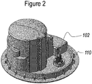
Figure 2 represents a module having a slightly different socket, in which a temperature sensor is mounted instead of a combined temperature and quality sensor. -
Figure 1 represents abase plate 110 of a delivery module for a vehicular fluid tank, in particular a urea solution tank of an SCR system. Reference is made toWO 2009/007405 , in the name of the present applicant, for a detailed description of a known module. Fluid communication between the inside and the outside of the tank is achieved by means of tubes passing through the base plate 110 (not visible in the views reproduced here). Thebase plate 110 is sometimes referred to in the art as the "flange". The module may be attached to a tank wall by placing it over an opening provided for that purpose, and securing it. - The module of
Figure 1 integrates a combined quality andtemperature sensor 101, i.e. a quality sensor also capable of measuring temperature. This allows replacing the temperature sensor of current designs by the quality and temperature sensor. The module design and the electronic architecture according to the invention are such that the combined quality and temperature sensor, and the "legacy" temperature sensor of the SCR module become intercheangeable. - In
Figure 2 , the module is shown with alegacy temperature sensor 102. - The interchangeability may be achieved with physically identical module forms (i.e., where the two types of sensors have the same footprint and the same mechanical mounting means), or with different module forms which can be produced with minimal changes to the moulding process (e.g., by moulding the actual mounting socket by means of an interchangeable socket). In both cases, the production process becomes highly uniform for both variants. In particular, the electrical interface at the bottom of the base plate (the side facing outwards of the tank, not visible in the views reproduced here) is identical for both variants, such that no distinction needs to be made in the further wiring and assembly process.
- The ECU is preferably capable of correctly reading the incoming signal on the same wire pair, regardless of whether the connected sensor is a combined quality and temperature sensor or a temperature sensor, notwithstanding the fact that sensors of the former type typically provide a digital signal, while sensors of the latter type provides an analog signal. The inventors have found that this effect can be achieved by branching the sensor signal in parallel towards a digital I/O port and to an analog (diagnostic) port. When the digital sensor signal on the digital input port is detected as timeout (continuous analog signal) and there is no fault detected on analog (diagnostic) input, then the temperature sensor is connected and the analog (diagnostic) port is used to measure the temperature sensor signal; otherwise the combined quality and temperature sensor is connected and the digital port is used to read the signal from the combined quality and temperature sensor.
- The module of the present invention may be mounted in a urea tank of an SCR system. The SCR system may be arranged in a vehicle with an internal combustion engine.
- While the invention has been described hereinabove with reference to separate embodiments, this was done for clarifying purposes only. The skilled person will appreciate that features described in connection one embodiment, can also be applied to other embodiments, with the same technical effects and advantages. Furthermore, the scope of the invention is not limited to these embodiments, but is defined by the accompanying claims.
Claims (5)
- A module for an SCR system, the module having a base plate (110) with a socket and a combined temperature and urea quality sensor (101) or alternatively a temperature-only sensor (102) mounted in said socket, the module further comprising an electrical interface connected to said combined temperature and urea quality sensor (101) or said temperature-only sensor (102) respectively, wherein the two types of sensors have the same footprint and the same mechanical mounting means, and wherein said electrical interface is adapted to alternatively connect to said combined temperature and urea quality sensor (101) or to said temperature sensor (102).
- An SCR system comprising a module according to claim 1 and an ECU, said electrical interface connecting said combined temperature and urea quality sensor (101) to said ECU, wherein said ECU is configured to read out a signal received via said electrical interface as digital sensor data.
- The SCR system according to claim 2, wherein said ECU is further configured to read out a signal received from said electrical interface as analog sensor data, when said signal originates from a temperature sensor (102).
- A motor vehicle comprising the SCR system according to claim 2 or claim 3.
- A process for manufacturing a module for an SCR system, the module having a base plate (110) with a socket and a sensor able to be mounted in said socket, the module further comprising an electrical interface able to be connected to said sensor, said process comprising the following step:- according to a first variant, moulding a module with a socket in which a combined temperature and urea quality sensor (101) is able to be mounted, or- according to a second variant, moulding a module of a different form than in said first variant, with a socket in which a temperature-only sensor (102) is able to be mounted, wherein the socket in the first variant and the socket in the second variant are interchangeable, andwherein said electrical interface is identical in each of the above variants of said module.
Priority Applications (4)
| Application Number | Priority Date | Filing Date | Title |
|---|---|---|---|
| EP13183685.0A EP2846014B1 (en) | 2013-09-10 | 2013-09-10 | Module for an SCR system and system comprising same. |
| US14/917,822 US20160222860A1 (en) | 2013-09-10 | 2014-09-10 | Module for an scr system and system comprising same |
| PCT/EP2014/069322 WO2015036449A1 (en) | 2013-09-10 | 2014-09-10 | Module for an scr system and system comprising same |
| CN201480047886.3A CN105531453B (en) | 2013-09-10 | 2014-09-10 | Module for an SCR system and system comprising the module |
Applications Claiming Priority (1)
| Application Number | Priority Date | Filing Date | Title |
|---|---|---|---|
| EP13183685.0A EP2846014B1 (en) | 2013-09-10 | 2013-09-10 | Module for an SCR system and system comprising same. |
Publications (2)
| Publication Number | Publication Date |
|---|---|
| EP2846014A1 EP2846014A1 (en) | 2015-03-11 |
| EP2846014B1 true EP2846014B1 (en) | 2017-03-15 |
Family
ID=49150803
Family Applications (1)
| Application Number | Title | Priority Date | Filing Date |
|---|---|---|---|
| EP13183685.0A Active EP2846014B1 (en) | 2013-09-10 | 2013-09-10 | Module for an SCR system and system comprising same. |
Country Status (4)
| Country | Link |
|---|---|
| US (1) | US20160222860A1 (en) |
| EP (1) | EP2846014B1 (en) |
| CN (1) | CN105531453B (en) |
| WO (1) | WO2015036449A1 (en) |
Families Citing this family (1)
| Publication number | Priority date | Publication date | Assignee | Title |
|---|---|---|---|---|
| IT201900010686A1 (en) * | 2019-07-02 | 2021-01-02 | Marelli Europe Spa | INTEGRATED MODULE FOR THE CONTROL AND MANAGEMENT OF LIQUIDS ON BOARD THE VEHICLE AND RELATED POWER GROUP FOR THE CONTROL, MANAGEMENT AND FEEDING OF LIQUIDS ON BOARD THE VEHICLE |
Family Cites Families (20)
| Publication number | Priority date | Publication date | Assignee | Title |
|---|---|---|---|---|
| US4684786A (en) * | 1984-08-01 | 1987-08-04 | Navistar International Corporation | Electrically heated fuel pick-up assembly for vehicle fuel tanks |
| US6063350A (en) * | 1997-04-02 | 2000-05-16 | Clean Diesel Technologies, Inc. | Reducing nox emissions from an engine by temperature-controlled urea injection for selective catalytic reduction |
| ES2182331T3 (en) * | 1998-06-30 | 2003-03-01 | Mitsubishi Electric Corp | FUEL FEEDING DEVICE FOR VEHICLES. |
| US6283731B1 (en) * | 1998-07-02 | 2001-09-04 | Mitsubishi Denki Kabushiki Kaisha | Vehicle fuel supplying apparatus |
| US20030186582A1 (en) * | 2002-03-27 | 2003-10-02 | Laukhuf Gregg E. | Worksurface power module with built in USB hub |
| US6743355B2 (en) * | 2002-09-11 | 2004-06-01 | Delphi Technologies, Inc. | Heated fuel strainer assembly |
| FR2845356B1 (en) * | 2002-10-04 | 2005-05-13 | Inergy Automotive Systems Res | PLASTIC PLASTIC ACCESSORY PLATE FOR THERMOPLASTIC HOLLOW BODY, TANK COMPRISING AN ATTACHMENT MOUNTED ON SUCH A PLATINUM AND METHOD FOR MANUFACTURING A FUEL TANK COMPRISING SUCH A PLATINUM |
| JP3751962B2 (en) * | 2003-09-05 | 2006-03-08 | 日産ディーゼル工業株式会社 | Engine exhaust purification system |
| JP3687916B2 (en) * | 2003-10-28 | 2005-08-24 | 日産ディーゼル工業株式会社 | Engine exhaust purification system |
| US7776265B2 (en) * | 2004-03-18 | 2010-08-17 | Cummins Filtration Ip, Inc. | System for diagnosing reagent solution quality |
| US7263823B2 (en) * | 2004-05-27 | 2007-09-04 | Cummins, Inc. | System for measuring NOx content of exhaust gas |
| JP4038492B2 (en) * | 2004-05-28 | 2008-01-23 | 三井金属鉱業株式会社 | Liquid type identification method and liquid type identification device |
| DE112006001140B4 (en) * | 2005-06-04 | 2014-06-05 | Eichenauer Heizelemente Gmbh & Co. Kg | Urea supply system for an exhaust gas purification catalyst and suitable heating insert for this purpose |
| DE202007019640U1 (en) * | 2006-06-08 | 2014-10-17 | Inergy Automotive Systems Research (Société A.) | System for storing engine gas additives |
| FR2918576B1 (en) | 2007-07-10 | 2009-10-09 | Inergy Automotive Systems Res | LIQUID SUPPLY SYSTEM FOR VEHICLE AND INTEGRATED PUMP / FILTER MODULE. |
| FR2919666B1 (en) * | 2007-08-03 | 2009-10-09 | Peugeot Citroen Automobiles Sa | SYSTEM FOR MANAGING A DISTRIBUTION CIRCUIT OF A REAGENT IN AN EXHAUST LINE |
| DE102010030060A1 (en) * | 2010-06-15 | 2011-12-15 | Robert Bosch Gmbh | Connector system, exhaust aftertreatment device |
| DE102010062985A1 (en) * | 2010-12-14 | 2012-04-19 | Robert Bosch Gmbh | Fluid extraction module, fluid tank |
| DE102011010640A1 (en) * | 2011-02-09 | 2012-08-09 | Emitec France S.A.S | Feed unit for conveying reducing agent |
| CN104145095B (en) * | 2012-02-28 | 2017-09-12 | 诺玛美国控股有限责任公司 | Automatic selectivity catalysis reduction (SCR) system sensor keeper and component |
-
2013
- 2013-09-10 EP EP13183685.0A patent/EP2846014B1/en active Active
-
2014
- 2014-09-10 US US14/917,822 patent/US20160222860A1/en not_active Abandoned
- 2014-09-10 CN CN201480047886.3A patent/CN105531453B/en active Active
- 2014-09-10 WO PCT/EP2014/069322 patent/WO2015036449A1/en active Application Filing
Non-Patent Citations (1)
| Title |
|---|
| None * |
Also Published As
| Publication number | Publication date |
|---|---|
| WO2015036449A1 (en) | 2015-03-19 |
| CN105531453A (en) | 2016-04-27 |
| CN105531453B (en) | 2018-10-09 |
| US20160222860A1 (en) | 2016-08-04 |
| EP2846014A1 (en) | 2015-03-11 |
Similar Documents
| Publication | Publication Date | Title |
|---|---|---|
| CN101868610B (en) | Fuel liquid and vapor pressure sensor | |
| KR101854591B1 (en) | Sensor device for detecting a flow property of a fluid medium | |
| US7478560B2 (en) | Sensor apparatus responsive to pressure and temperature within a vessel | |
| CN101558285B (en) | Method for manufacturing a mounting element with an angle sensor | |
| US8757001B2 (en) | Mechanically coupled force sensor on flexible platform assembly structure | |
| EP2568139A1 (en) | Integrated connection device for connecting several sensors | |
| KR102240523B1 (en) | Pressure sensor device, air-mass-flow measurement device, air-mass-flow measurement system, and pressure measurement method | |
| JP2008197001A (en) | Pressure sensor | |
| US20170288346A1 (en) | Plug housing for a sensor device and plug module | |
| KR20170067780A (en) | Pressure sensor for sensing a pressure of a fluid medium | |
| CN209400120U (en) | Pressure sensor | |
| EP2846014B1 (en) | Module for an SCR system and system comprising same. | |
| KR102313055B1 (en) | Air mass measuring apparatus, air mass measuring system and air mass measuring method for a vehicle | |
| WO2011042795A1 (en) | Integrated fluid pressure sensor system | |
| JP2009047670A (en) | Pressure sensor | |
| US20190383195A1 (en) | Connection head with a return cavity | |
| CN109990942A (en) | A kind of high-pressure common-rail pressure sensor | |
| JP2014092430A (en) | Flow rate measuring device | |
| JP2015017849A (en) | Temperature and humidity measuring device | |
| CN219829993U (en) | Engine combustion oil mass metering device | |
| JP2005257498A (en) | Pressure sensor | |
| CN214373098U (en) | GPF pressure sensor device for vehicle | |
| JP2014006141A (en) | Pressure sensor device | |
| JP6111766B2 (en) | Pressure sensor mounting structure and mounting method | |
| CN213874545U (en) | Liquid level sensor bottom end fixed knot constructs |
Legal Events
| Date | Code | Title | Description |
|---|---|---|---|
| 17P | Request for examination filed |
Effective date: 20130910 |
|
| AK | Designated contracting states |
Kind code of ref document: A1 Designated state(s): AL AT BE BG CH CY CZ DE DK EE ES FI FR GB GR HR HU IE IS IT LI LT LU LV MC MK MT NL NO PL PT RO RS SE SI SK SM TR |
|
| AX | Request for extension of the european patent |
Extension state: BA ME |
|
| PUAI | Public reference made under article 153(3) epc to a published international application that has entered the european phase |
Free format text: ORIGINAL CODE: 0009012 |
|
| R17P | Request for examination filed (corrected) |
Effective date: 20150910 |
|
| RBV | Designated contracting states (corrected) |
Designated state(s): AL AT BE BG CH CY CZ DE DK EE ES FI FR GB GR HR HU IE IS IT LI LT LU LV MC MK MT NL NO PL PT RO RS SE SI SK SM TR |
|
| 17Q | First examination report despatched |
Effective date: 20160323 |
|
| GRAP | Despatch of communication of intention to grant a patent |
Free format text: ORIGINAL CODE: EPIDOSNIGR1 |
|
| INTG | Intention to grant announced |
Effective date: 20161007 |
|
| GRAS | Grant fee paid |
Free format text: ORIGINAL CODE: EPIDOSNIGR3 |
|
| GRAA | (expected) grant |
Free format text: ORIGINAL CODE: 0009210 |
|
| AK | Designated contracting states |
Kind code of ref document: B1 Designated state(s): AL AT BE BG CH CY CZ DE DK EE ES FI FR GB GR HR HU IE IS IT LI LT LU LV MC MK MT NL NO PL PT RO RS SE SI SK SM TR |
|
| REG | Reference to a national code |
Ref country code: CH Ref legal event code: EP Ref country code: GB Ref legal event code: FG4D |
|
| REG | Reference to a national code |
Ref country code: IE Ref legal event code: FG4D |
|
| REG | Reference to a national code |
Ref country code: AT Ref legal event code: REF Ref document number: 875838 Country of ref document: AT Kind code of ref document: T Effective date: 20170415 |
|
| REG | Reference to a national code |
Ref country code: DE Ref legal event code: R096 Ref document number: 602013018503 Country of ref document: DE |
|
| REG | Reference to a national code |
Ref country code: NL Ref legal event code: MP Effective date: 20170315 |
|
| REG | Reference to a national code |
Ref country code: LT Ref legal event code: MG4D |
|
| PG25 | Lapsed in a contracting state [announced via postgrant information from national office to epo] |
Ref country code: GR Free format text: LAPSE BECAUSE OF FAILURE TO SUBMIT A TRANSLATION OF THE DESCRIPTION OR TO PAY THE FEE WITHIN THE PRESCRIBED TIME-LIMIT Effective date: 20170616 Ref country code: LT Free format text: LAPSE BECAUSE OF FAILURE TO SUBMIT A TRANSLATION OF THE DESCRIPTION OR TO PAY THE FEE WITHIN THE PRESCRIBED TIME-LIMIT Effective date: 20170315 Ref country code: FI Free format text: LAPSE BECAUSE OF FAILURE TO SUBMIT A TRANSLATION OF THE DESCRIPTION OR TO PAY THE FEE WITHIN THE PRESCRIBED TIME-LIMIT Effective date: 20170315 Ref country code: HR Free format text: LAPSE BECAUSE OF FAILURE TO SUBMIT A TRANSLATION OF THE DESCRIPTION OR TO PAY THE FEE WITHIN THE PRESCRIBED TIME-LIMIT Effective date: 20170315 Ref country code: NO Free format text: LAPSE BECAUSE OF FAILURE TO SUBMIT A TRANSLATION OF THE DESCRIPTION OR TO PAY THE FEE WITHIN THE PRESCRIBED TIME-LIMIT Effective date: 20170615 |
|
| REG | Reference to a national code |
Ref country code: AT Ref legal event code: MK05 Ref document number: 875838 Country of ref document: AT Kind code of ref document: T Effective date: 20170315 |
|
| PG25 | Lapsed in a contracting state [announced via postgrant information from national office to epo] |
Ref country code: BG Free format text: LAPSE BECAUSE OF FAILURE TO SUBMIT A TRANSLATION OF THE DESCRIPTION OR TO PAY THE FEE WITHIN THE PRESCRIBED TIME-LIMIT Effective date: 20170615 Ref country code: RS Free format text: LAPSE BECAUSE OF FAILURE TO SUBMIT A TRANSLATION OF THE DESCRIPTION OR TO PAY THE FEE WITHIN THE PRESCRIBED TIME-LIMIT Effective date: 20170315 Ref country code: SE Free format text: LAPSE BECAUSE OF FAILURE TO SUBMIT A TRANSLATION OF THE DESCRIPTION OR TO PAY THE FEE WITHIN THE PRESCRIBED TIME-LIMIT Effective date: 20170315 Ref country code: LV Free format text: LAPSE BECAUSE OF FAILURE TO SUBMIT A TRANSLATION OF THE DESCRIPTION OR TO PAY THE FEE WITHIN THE PRESCRIBED TIME-LIMIT Effective date: 20170315 |
|
| REG | Reference to a national code |
Ref country code: FR Ref legal event code: PLFP Year of fee payment: 5 |
|
| PG25 | Lapsed in a contracting state [announced via postgrant information from national office to epo] |
Ref country code: NL Free format text: LAPSE BECAUSE OF FAILURE TO SUBMIT A TRANSLATION OF THE DESCRIPTION OR TO PAY THE FEE WITHIN THE PRESCRIBED TIME-LIMIT Effective date: 20170315 |
|
| PG25 | Lapsed in a contracting state [announced via postgrant information from national office to epo] |
Ref country code: RO Free format text: LAPSE BECAUSE OF FAILURE TO SUBMIT A TRANSLATION OF THE DESCRIPTION OR TO PAY THE FEE WITHIN THE PRESCRIBED TIME-LIMIT Effective date: 20170315 Ref country code: CZ Free format text: LAPSE BECAUSE OF FAILURE TO SUBMIT A TRANSLATION OF THE DESCRIPTION OR TO PAY THE FEE WITHIN THE PRESCRIBED TIME-LIMIT Effective date: 20170315 Ref country code: EE Free format text: LAPSE BECAUSE OF FAILURE TO SUBMIT A TRANSLATION OF THE DESCRIPTION OR TO PAY THE FEE WITHIN THE PRESCRIBED TIME-LIMIT Effective date: 20170315 Ref country code: SK Free format text: LAPSE BECAUSE OF FAILURE TO SUBMIT A TRANSLATION OF THE DESCRIPTION OR TO PAY THE FEE WITHIN THE PRESCRIBED TIME-LIMIT Effective date: 20170315 Ref country code: AT Free format text: LAPSE BECAUSE OF FAILURE TO SUBMIT A TRANSLATION OF THE DESCRIPTION OR TO PAY THE FEE WITHIN THE PRESCRIBED TIME-LIMIT Effective date: 20170315 Ref country code: ES Free format text: LAPSE BECAUSE OF FAILURE TO SUBMIT A TRANSLATION OF THE DESCRIPTION OR TO PAY THE FEE WITHIN THE PRESCRIBED TIME-LIMIT Effective date: 20170315 Ref country code: IT Free format text: LAPSE BECAUSE OF FAILURE TO SUBMIT A TRANSLATION OF THE DESCRIPTION OR TO PAY THE FEE WITHIN THE PRESCRIBED TIME-LIMIT Effective date: 20170315 |
|
| PG25 | Lapsed in a contracting state [announced via postgrant information from national office to epo] |
Ref country code: PT Free format text: LAPSE BECAUSE OF FAILURE TO SUBMIT A TRANSLATION OF THE DESCRIPTION OR TO PAY THE FEE WITHIN THE PRESCRIBED TIME-LIMIT Effective date: 20170717 Ref country code: SM Free format text: LAPSE BECAUSE OF FAILURE TO SUBMIT A TRANSLATION OF THE DESCRIPTION OR TO PAY THE FEE WITHIN THE PRESCRIBED TIME-LIMIT Effective date: 20170315 Ref country code: IS Free format text: LAPSE BECAUSE OF FAILURE TO SUBMIT A TRANSLATION OF THE DESCRIPTION OR TO PAY THE FEE WITHIN THE PRESCRIBED TIME-LIMIT Effective date: 20170715 Ref country code: PL Free format text: LAPSE BECAUSE OF FAILURE TO SUBMIT A TRANSLATION OF THE DESCRIPTION OR TO PAY THE FEE WITHIN THE PRESCRIBED TIME-LIMIT Effective date: 20170315 |
|
| REG | Reference to a national code |
Ref country code: DE Ref legal event code: R097 Ref document number: 602013018503 Country of ref document: DE |
|
| PLBE | No opposition filed within time limit |
Free format text: ORIGINAL CODE: 0009261 |
|
| STAA | Information on the status of an ep patent application or granted ep patent |
Free format text: STATUS: NO OPPOSITION FILED WITHIN TIME LIMIT |
|
| PG25 | Lapsed in a contracting state [announced via postgrant information from national office to epo] |
Ref country code: DK Free format text: LAPSE BECAUSE OF FAILURE TO SUBMIT A TRANSLATION OF THE DESCRIPTION OR TO PAY THE FEE WITHIN THE PRESCRIBED TIME-LIMIT Effective date: 20170315 |
|
| 26N | No opposition filed |
Effective date: 20171218 |
|
| PG25 | Lapsed in a contracting state [announced via postgrant information from national office to epo] |
Ref country code: SI Free format text: LAPSE BECAUSE OF FAILURE TO SUBMIT A TRANSLATION OF THE DESCRIPTION OR TO PAY THE FEE WITHIN THE PRESCRIBED TIME-LIMIT Effective date: 20170315 |
|
| REG | Reference to a national code |
Ref country code: CH Ref legal event code: PL |
|
| GBPC | Gb: european patent ceased through non-payment of renewal fee |
Effective date: 20170910 |
|
| PG25 | Lapsed in a contracting state [announced via postgrant information from national office to epo] |
Ref country code: MC Free format text: LAPSE BECAUSE OF FAILURE TO SUBMIT A TRANSLATION OF THE DESCRIPTION OR TO PAY THE FEE WITHIN THE PRESCRIBED TIME-LIMIT Effective date: 20170315 |
|
| REG | Reference to a national code |
Ref country code: IE Ref legal event code: MM4A |
|
| REG | Reference to a national code |
Ref country code: BE Ref legal event code: MM Effective date: 20170930 |
|
| PG25 | Lapsed in a contracting state [announced via postgrant information from national office to epo] |
Ref country code: LU Free format text: LAPSE BECAUSE OF NON-PAYMENT OF DUE FEES Effective date: 20170910 |
|
| PG25 | Lapsed in a contracting state [announced via postgrant information from national office to epo] |
Ref country code: GB Free format text: LAPSE BECAUSE OF NON-PAYMENT OF DUE FEES Effective date: 20170910 Ref country code: CH Free format text: LAPSE BECAUSE OF NON-PAYMENT OF DUE FEES Effective date: 20170930 Ref country code: LI Free format text: LAPSE BECAUSE OF NON-PAYMENT OF DUE FEES Effective date: 20170930 Ref country code: IE Free format text: LAPSE BECAUSE OF NON-PAYMENT OF DUE FEES Effective date: 20170910 |
|
| PG25 | Lapsed in a contracting state [announced via postgrant information from national office to epo] |
Ref country code: BE Free format text: LAPSE BECAUSE OF NON-PAYMENT OF DUE FEES Effective date: 20170930 |
|
| REG | Reference to a national code |
Ref country code: FR Ref legal event code: PLFP Year of fee payment: 6 |
|
| PG25 | Lapsed in a contracting state [announced via postgrant information from national office to epo] |
Ref country code: MT Free format text: LAPSE BECAUSE OF NON-PAYMENT OF DUE FEES Effective date: 20170910 |
|
| PG25 | Lapsed in a contracting state [announced via postgrant information from national office to epo] |
Ref country code: HU Free format text: LAPSE BECAUSE OF FAILURE TO SUBMIT A TRANSLATION OF THE DESCRIPTION OR TO PAY THE FEE WITHIN THE PRESCRIBED TIME-LIMIT; INVALID AB INITIO Effective date: 20130910 |
|
| PG25 | Lapsed in a contracting state [announced via postgrant information from national office to epo] |
Ref country code: CY Free format text: LAPSE BECAUSE OF FAILURE TO SUBMIT A TRANSLATION OF THE DESCRIPTION OR TO PAY THE FEE WITHIN THE PRESCRIBED TIME-LIMIT Effective date: 20170315 |
|
| PG25 | Lapsed in a contracting state [announced via postgrant information from national office to epo] |
Ref country code: MK Free format text: LAPSE BECAUSE OF FAILURE TO SUBMIT A TRANSLATION OF THE DESCRIPTION OR TO PAY THE FEE WITHIN THE PRESCRIBED TIME-LIMIT Effective date: 20170315 |
|
| PG25 | Lapsed in a contracting state [announced via postgrant information from national office to epo] |
Ref country code: TR Free format text: LAPSE BECAUSE OF FAILURE TO SUBMIT A TRANSLATION OF THE DESCRIPTION OR TO PAY THE FEE WITHIN THE PRESCRIBED TIME-LIMIT Effective date: 20170315 |
|
| PG25 | Lapsed in a contracting state [announced via postgrant information from national office to epo] |
Ref country code: AL Free format text: LAPSE BECAUSE OF FAILURE TO SUBMIT A TRANSLATION OF THE DESCRIPTION OR TO PAY THE FEE WITHIN THE PRESCRIBED TIME-LIMIT Effective date: 20170315 |
|
| P01 | Opt-out of the competence of the unified patent court (upc) registered |
Effective date: 20230515 |
|
| PGFP | Annual fee paid to national office [announced via postgrant information from national office to epo] |
Ref country code: FR Payment date: 20230929 Year of fee payment: 11 Ref country code: DE Payment date: 20230920 Year of fee payment: 11 |