JP6129474B2 - X-ray diagnostic equipment - Google Patents
X-ray diagnostic equipment Download PDFInfo
- Publication number
- JP6129474B2 JP6129474B2 JP2012025848A JP2012025848A JP6129474B2 JP 6129474 B2 JP6129474 B2 JP 6129474B2 JP 2012025848 A JP2012025848 A JP 2012025848A JP 2012025848 A JP2012025848 A JP 2012025848A JP 6129474 B2 JP6129474 B2 JP 6129474B2
- Authority
- JP
- Japan
- Prior art keywords
- ray
- unit
- tube current
- data
- image
- Prior art date
- Legal status (The legal status is an assumption and is not a legal conclusion. Google has not performed a legal analysis and makes no representation as to the accuracy of the status listed.)
- Active
Links
- 238000003384 imaging method Methods 0.000 claims description 34
- 230000005540 biological transmission Effects 0.000 claims description 15
- 238000009826 distribution Methods 0.000 claims description 14
- 238000013480 data collection Methods 0.000 claims description 10
- 238000003860 storage Methods 0.000 description 13
- 238000000034 method Methods 0.000 description 12
- 230000008569 process Effects 0.000 description 9
- 230000008859 change Effects 0.000 description 5
- 238000002405 diagnostic procedure Methods 0.000 description 3
- 238000006243 chemical reaction Methods 0.000 description 2
- 238000002591 computed tomography Methods 0.000 description 2
- 238000001514 detection method Methods 0.000 description 2
- 230000001678 irradiating effect Effects 0.000 description 2
- 238000004519 manufacturing process Methods 0.000 description 2
- 230000003287 optical effect Effects 0.000 description 2
- 230000000903 blocking effect Effects 0.000 description 1
- 230000006870 function Effects 0.000 description 1
- 239000004973 liquid crystal related substance Substances 0.000 description 1
- 230000007246 mechanism Effects 0.000 description 1
- 238000012986 modification Methods 0.000 description 1
- 230000004048 modification Effects 0.000 description 1
- 238000007781 pre-processing Methods 0.000 description 1
- 230000009467 reduction Effects 0.000 description 1
- 230000004044 response Effects 0.000 description 1
- 239000004065 semiconductor Substances 0.000 description 1
- 238000000926 separation method Methods 0.000 description 1
- XLYOFNOQVPJJNP-UHFFFAOYSA-N water Substances O XLYOFNOQVPJJNP-UHFFFAOYSA-N 0.000 description 1
Images


Classifications
-
- A—HUMAN NECESSITIES
- A61—MEDICAL OR VETERINARY SCIENCE; HYGIENE
- A61B—DIAGNOSIS; SURGERY; IDENTIFICATION
- A61B6/00—Apparatus for radiation diagnosis, e.g. combined with radiation therapy equipment
- A61B6/54—Control of apparatus or devices for radiation diagnosis
-
- A—HUMAN NECESSITIES
- A61—MEDICAL OR VETERINARY SCIENCE; HYGIENE
- A61B—DIAGNOSIS; SURGERY; IDENTIFICATION
- A61B6/00—Apparatus for radiation diagnosis, e.g. combined with radiation therapy equipment
- A61B6/02—Devices for diagnosis sequentially in different planes; Stereoscopic radiation diagnosis
- A61B6/03—Computerised tomographs
- A61B6/032—Transmission computed tomography [CT]
-
- A—HUMAN NECESSITIES
- A61—MEDICAL OR VETERINARY SCIENCE; HYGIENE
- A61B—DIAGNOSIS; SURGERY; IDENTIFICATION
- A61B6/00—Apparatus for radiation diagnosis, e.g. combined with radiation therapy equipment
- A61B6/48—Diagnostic techniques
- A61B6/488—Diagnostic techniques involving pre-scan acquisition
-
- A—HUMAN NECESSITIES
- A61—MEDICAL OR VETERINARY SCIENCE; HYGIENE
- A61B—DIAGNOSIS; SURGERY; IDENTIFICATION
- A61B6/00—Apparatus for radiation diagnosis, e.g. combined with radiation therapy equipment
- A61B6/54—Control of apparatus or devices for radiation diagnosis
- A61B6/542—Control of apparatus or devices for radiation diagnosis involving control of exposure
-
- A—HUMAN NECESSITIES
- A61—MEDICAL OR VETERINARY SCIENCE; HYGIENE
- A61B—DIAGNOSIS; SURGERY; IDENTIFICATION
- A61B6/00—Apparatus for radiation diagnosis, e.g. combined with radiation therapy equipment
- A61B6/54—Control of apparatus or devices for radiation diagnosis
- A61B6/545—Control of apparatus or devices for radiation diagnosis involving automatic set-up of acquisition parameters
Description
本発明の実施形態は、X線診断装置及びX線診断方法に関する。 Embodiments described herein relate generally to an X-ray diagnostic apparatus and an X-ray diagnostic method.
X線診断装置は、患者などの被検体に対してX線を照射し、その被検体を透過したX線を検出し、検出したX線の線量分布データ(X線透過データ)をデータ収集装置により収集する。その後、X線診断装置は、線量分布データに対して再構成処理を行い、被検体のスライス画像(断層画像)を生成する。このX線診断装置としては、例えば、被検体を間にしてX線照射器とX線検出器とを対向配置し、それらを被検体の体軸まわりに回転させながら撮像を行うX線CT装置(X線コンピュータ断層撮像装置)が開発されている。 The X-ray diagnostic apparatus irradiates a subject such as a patient with X-rays, detects X-rays transmitted through the subject, and collects the detected X-ray dose distribution data (X-ray transmission data). Collect by. Thereafter, the X-ray diagnostic apparatus performs a reconstruction process on the dose distribution data to generate a slice image (tomographic image) of the subject. As this X-ray diagnostic apparatus, for example, an X-ray CT apparatus that performs imaging while arranging an X-ray irradiator and an X-ray detector facing each other with a subject interposed therebetween and rotating them around the body axis of the subject (X-ray computed tomography apparatus) has been developed.
このようなX線診断装置では、通常、マルチスライススキャンやヘリカルスキャンなどの撮像前にスキャン範囲(撮像範囲)を設定するため、X線照射器及びX線検出器を回転させずに撮像を行い、スキャノ画像(位置決め画像)を収集する。このX線診断装置の中には、そのスキャノ画像を用いて部位ごとの厚みを水等価厚に変換し、指定したSD(標準偏差)により管電流値(mA)を決定するAEC(Auto Exposure Control)を搭載した製品が既に存在している。 In such an X-ray diagnostic apparatus, in general, a scan range (imaging range) is set before imaging such as multi-slice scanning or helical scanning, so imaging is performed without rotating the X-ray irradiator and the X-ray detector. The scanogram (positioning image) is collected. This X-ray diagnostic device uses the scan image to convert the thickness of each part into a water equivalent thickness and determines the tube current value (mA) based on the specified SD (standard deviation). ) Already exists.
このAECでは、スキャノ画像から被検体の各部位の体厚に合ったX線量を自動的に計算し、その後、X線照射器及びX線検出器の回転ごとにX線量、すなわち管電流を細かく制御する。これにより、高画質を維持しつつ不要な被曝を抑え、被曝低減を実現している。 In this AEC, an X-ray dose corresponding to the body thickness of each part of the subject is automatically calculated from the scan image, and then the X-ray dose, that is, the tube current is finely divided for each rotation of the X-ray irradiator and the X-ray detector. Control. As a result, unnecessary exposure is suppressed while maintaining high image quality, and exposure reduction is realized.
しかしながら、前述のような技術では、被検体の大きさ(体厚)に応じて管電流が調整されるが、その調整により決定された管電流は、装置性能上の最大値及び最小値の範囲内で調整されたものである。このため、オーバーフローアーチファクト(例えば、データ収集装置内で扱えるカウントの最大値を超え、再構成画像上に現れるアーチファクト)やダークバンドアーチファクト(例えば、X線の線量不足、つまり生データカウント不足による再構成画像上に現れるアーチファクト)などのアーチファクトが発生することがあり、断層画像などのX線画像の画質が低下してしまう。 However, in the technique as described above, the tube current is adjusted according to the size (body thickness) of the subject, and the tube current determined by the adjustment is within the range of the maximum value and the minimum value in the apparatus performance. It has been adjusted within. For this reason, overflow artifacts (for example, artifacts that exceed the maximum count that can be handled in the data acquisition device and appear on the reconstructed image) and dark band artifacts (for example, reconstruction due to insufficient X-ray dose, that is, insufficient raw data count) Artifacts such as artifacts appearing on the image may occur, and the quality of X-ray images such as tomographic images will deteriorate.
本発明が解決しようとする課題は、X線画像の画質を向上させることができるX線診断装置及びX線診断方法を提供することである。 The problem to be solved by the present invention is to provide an X-ray diagnostic apparatus and an X-ray diagnostic method capable of improving the image quality of an X-ray image.
実施形態に係るX線診断装置は、被検体の位置決め画像を撮像する場合の管電流を設定する管電流設定部と、管電流設定部により設定された位置決め画像を撮像する場合の管電流に基づいて被検体に対してX線を出射するX線管と、X線管により出射されて被検体を透過したX線を検出するX線検出器と、X線検出器により検出されたX線の透過データを収集するデータ収集部と、データ収集部により収集された透過データから位置決め画像を生成する画像処理部と、画像処理部により生成された位置決め画像又は画像処理部により位置決め画像を生成する途中に生じる第1データから、X線の線量分布を示す第2データを生成するデータ生成部と、データ生成部により生成された第2データに対して閾値を設定する閾値設定部と、データ生成部により生成された第2データ内のX線量と閾値設定部により設定された閾値との比較に応じ、被検体の断層画像を撮像する場合の管電流を調整する管電流調整部とを備える。 The X-ray diagnostic apparatus according to the embodiment is based on a tube current setting unit that sets a tube current when a positioning image of a subject is captured, and a tube current when a positioning image set by the tube current setting unit is captured. and X-ray tube for emitting X-rays to a subject Te, and X-ray detector for detecting X-rays passed permeable the subject is emitted by the X-ray tube, X-rays detected by the X-ray detector to the generation and data collection unit for collecting transmission data, an image processing unit that generates positioning image from the transmission data collected by the data collecting unit, the positioning image by positioning the image or the image processing unit generated by the image processing unit from the first data generated in the course, the threshold setting for setting the second data to generate a Lud over data generator shown a dose distribution of the X-ray, the threshold for the second data generated by the data generating unit and parts, data production Depending on the comparison of the set threshold by X-ray dose and the threshold value setting unit in the second data generated by section, and a tube current adjustment unit for adjusting the tube current in the case of imaging a tomographic image of the subject.
実施形態に係るX線診断方法は、被検体の位置決め画像を撮像する場合の管電流を設定する工程と、設定した位置決め画像を撮像する場合の管電流に基づいて被検体に対して出射され、被検体を透過したX線を検出する工程と、検出したX線の透過データを収集する工程と、収集した透過データから位置決め画像を生成する工程と、生成した位置決め画像又は位置決め画像を生成する途中に生じる第1データから、X線の線量分布を示す第2データを生成する工程と、生成した第2データに対して閾値を設定する工程と、生成した第2データ内のX線量と設定した閾値との比較に応じ、被検体の断層画像を撮像する場合の管電流を調整する工程とを有する。 The X-ray diagnostic method according to the embodiment is emitted to the subject based on the step of setting the tube current when imaging a positioning image of the subject and the tube current when imaging the set positioning image, A step of detecting X-rays transmitted through the subject, a step of collecting transmission data of the detected X-rays, a step of generating a positioning image from the collected transmission data, and a step of generating the generated positioning image or positioning image The second data indicating the X-ray dose distribution, the step of setting a threshold for the generated second data, and the X-ray dose in the generated second data are set from the first data generated in And adjusting the tube current when capturing a tomographic image of the subject in accordance with the comparison with the threshold value.
実施の一形態について図面を参照して説明する。 An embodiment will be described with reference to the drawings.
図1に示すように、本実施形態に係るX線診断装置1は、患者などの被検体Pが横たわる寝台2と、その寝台2上の被検体Pに対して撮像を行う撮像装置3と、それらの寝台2及び撮像装置3を制御する制御装置4とを備えている。このX線診断装置1としては、例えば、X線CT装置(X線コンピュータ断層撮像装置)が挙げられる。
As shown in FIG. 1, an X-ray
寝台2は、被検体Pを載せる長方形状の天板2aと、その天板2aを支持して水平方向及び鉛直方向(昇降方向)に移動させる天板駆動部2bとを備えている。天板駆動部2bは、天板2aを移動させるための移動機構やその移動のための駆動力を供給する駆動源などを有している。この寝台2は、天板駆動部2bにより天板2aを所望の高さまで移動させ、さらに、その天板2aを水平方向に移動させて、天板2a上の被検体Pを所望位置まで移動させる。
The
撮像装置3は、筐体となるCT架台内に回転可能に設けられた回転体3aと、その回転体3aを回転させる回転駆動部3bと、X線を照射するX線照射器3cと、そのX線照射器3cに高電圧を供給する高電圧発生部3dと、天板2a上の被検体Pを透過したX線を検出するX線検出器3eと、そのX線検出器3eにより検出されたX線をX線量分布データ(X線透過データ)として収集するデータ収集部3fとを備えている。
The
回転体3aは、X線照射器3cやX線検出器3eなどを支持して回転する円環状の回転枠である。この回転体3aにX線照射器3c及びX線検出器3eが設けられおり、それらのX線照射器3c及びX線検出器3eは天板2a上の被検体Pを間にし、その被検体Pの周囲を被検体Pの体軸周りに回転する。
The rotating
回転駆動部3bは、撮像装置3のCT架台内に設けられている。この回転駆動部3bは、制御装置4による制御に応じて、回転体3aの回転駆動を行う。例えば、回転駆動部3bは、制御装置4から送信された制御信号に基づいて、一方向に所定の回転スピードで回転体3aを回転させる。
The
X線照射器3cは、X線を出射するX線管3c1と、そのX線管3c1から出射されたX線を絞るコリメータなどの絞り器3c2とを備えており、回転体3aに固定されている。このX線照射器3cは、X線管3c1によりX線を出射し、そのX線を絞り器3c2により絞って、天板2a上の被検体Pに対しコーン角を持つファンビーム形状、例えば、角錐形状のX線を照射する。
The
ここで、絞り器3c2としては、様々なタイプの絞り器を用いることが可能である。例えば、鉛のような二枚のX線遮断板を互いに接離方向に移動させ、それらのX線遮断板により形成される隙間の大きさを適宜変更する絞り器を用いても良い。その隙間の部分がX線の通過領域となり、その隙間以外の部分がX線を遮断する遮断領域となる。このような絞り器3c2によってX線の照射野(照射範囲)を調整することが可能である。 Here, various types of restrictors can be used as the restrictor 3c2. For example, a diaphragm that moves two X-ray shielding plates such as lead in the contact and separation directions and appropriately changes the size of the gap formed by these X-ray shielding plates may be used. The gap portion serves as an X-ray passage region, and the portion other than the gap serves as a blocking region that blocks X-rays. It is possible to adjust the irradiation field (irradiation range) of X-rays by using the diaphragm 3c2.
高電圧発生部3dは、撮像装置3のCT架台内に設けられている。この高電圧発生部3dは、X線照射器3cのX線管3c1に供給する高電圧を発生させる装置であり、制御装置4から与えられた電圧を昇圧及び整流し、その電圧をX線管3c1に供給する。なお、制御装置4は、X線管3c1により所望のX線を発生させるため、高電圧発生部3dに与える電圧の波形、すなわち振幅やパルス幅などの各種条件を制御する。
The
X線検出器3eは、X線照射器3cに対向するように回転体3aに固定されている。このX線検出器3eは、天板2a上の被検体Pを透過したX線を電気信号に変換してデータ収集部3fに送信する。X線検出器3eは、多列多チャンネルのX線検出器であり、X線を検出するX線検出素子が格子状に配列されて構成されている。なお、チャンネル列はX線検出素子がチャンネル方向(被検体Pの体軸周り方向)に複数(例えば、数百から数千程度)並んでいる列であり、そのチャンネル列が列方向(被検体Pの体軸方向)に沿って複数列(例えば、16列や64列など)配置されている。
The
ここで、X線検出器3eとしては、フォトン(光子)をカウントする光子計数(フォトンカウンディング)方式のX線検出器を用いているが、これに限るものではなく、X線を直接電気信号に変換する直接変換方式(例えば、平面検出器)であっても、あるいは、X線を光学情報に変換してその光学情報を電気信号に変換する間接変換方式であっても良い。
Here, as the
データ収集部3fは、撮像装置3のCT架台内に設けられている。このデータ収集部3fは、X線検出器3eから送信された電気信号をデジタル信号に変換し、デジタルデータであるX線透過データ(X線量分布データ)を収集し、そのX線透過データを制御装置4に送信する。
The
制御装置4は、各部を制御する制御部4aと、X線透過データに対して各種画像処理を行う画像処理部4bと、各種プログラムや各種データなどを記憶する記憶部4cと、ユーザ(利用者)により入力操作される操作部4dと、画像を表示する表示部4eとを備えている。これらの制御部4a、画像処理部4b、記憶部4c、操作部4d及び表示4eはバスライン4fにより電気的に接続されている。
The
制御部4aは、記憶部4cに記憶された各種プログラムや各種データに基づいて寝台2の天板駆動部2b、撮像装置3の回転駆動部3b及び高電圧発生部3dなどの各部を制御する。加えて、制御部4aは、X線照射器3cの絞り器3c2も制御し、さらに、表示部4eにX線画像などの各種画像を表示する表示制御も行う。この制御部4aとしては、例えば、CPU(Central Processing Unit)などを用いることが可能である。
The
画像処理部4bは、データ収集部3fから送信されたX線透過データを投影データとする前処理やその投影データに対して画像再構成を行う画像再構成処理、さらに、スキャノ画像を生成するスキャノ画像生成処理などの画像処理を行う。この画像処理部4bとしては、例えばアレイプロセッサなどを用いることが可能である。
The
記憶部4cは、各種プログラムや各種データなどを記憶する記憶装置であり、例えば、各種データとしてスキャノ画像(位置決め画像)やスライス画像(断層画像)を記憶する。この記憶部4cとしては、例えば、ROM(Read Only Memory)やRAM(Random Access Memory)に加え、ハードディスク(磁気ディスク装置)やフラッシュメモリ(半導体ディスク装置)などを用いることが可能である。
The
操作部4dは、ユーザによる入力操作を受け付ける入力部であり、例えば、撮像指示や画像表示、画像の切り替え、各種設定などの様々な入力操作を受け付ける。この操作部4dとしては、例えば、キーボードやマウス、レバーなどの入力デバイスを用いることが可能である。
The
表示部4eは、被検体Pのスキャノ画像や断層画像、操作画面などの各種画像を表示する表示装置である。この表示部4eとしては、例えば、液晶ディスプレイやCRT(ブラウン管)ディスプレイなどを用いることが可能である。
The
ここで、前述のX線診断装置1では、各種の撮像モードがあり、例えば、スキャノ画像を撮像するスキャノ撮像モードやスライス画像を撮像する断層撮像モードなどがある。この断層撮像モードとしては、例えば、通常のマルチスライススキャンモード(ノーマルCT)やヘリカルスキャンモード(ヘリカルCT)、ボリュームスキャンモード(ボリュームCT)などが挙げられる。
Here, the above-described X-ray
スキャノ撮像モードは、断層撮像モードによる撮像に先立って、位置決めやスキャン範囲(撮像範囲)を設定するためのスキャノ画像を撮像するモードである。例えば、スキャン計画では、事前にスキャノ画像を撮像し、そのスキャノ画像を表示部4eにより表示し、作業者はそのスキャノ画像を確認し、操作部4dを入力操作してスキャン範囲を設定する。
The scano imaging mode is a mode for imaging a scanogram for setting positioning and a scan range (imaging range) prior to imaging in the tomographic imaging mode. For example, in the scan plan, a scano image is captured in advance, the scano image is displayed on the
スキャノ画像の撮像では、X線照射器3cとX線検出器3eとを所定位置、すなわち所定のビュー角度(例えば、0度や90度)で固定し、寝台2の天板2aを被検体Pの体軸方向に所定位置まで移動させ、X線照射器3cによりX線を照射して天板2a上の被検体Pを透過したX線をX線検出器3eにより検出し、X線透過データの収集を行う。その後、収集したX線透過データを画像処理部4bにより処理してスキャノ画像を生成し、その生成したスキャノ画像を記憶部4cに保存し、加えて、表示部4eに表示する。
In capturing a scanogram, the
一方、断層画像の撮像では、X線照射器3cとX線検出器3eとを回転させ、寝台2の天板2aを被検体Pの体軸方向に移動させながら、X線照射器3cによりX線を照射して天板2a上の被検体Pを透過したX線をX線検出器3eにより検出し、X線透過データの収集を行う。その後、収集したX線透過データを画像処理部4bにより処理して断層画像を生成し、その生成した断層画像を記憶部4cに保存し、加えて、表示部4eに表示する。
On the other hand, in tomographic imaging, the
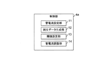
ここで、前述の制御部4aについて詳しく説明する。
Here, the
図2に示すように、制御部4aは、被検体Pのスキャノ画像を撮像する場合の管電流を設定する管電流設定部11と、スキャノ画像から生データを求め、その生データから純生データ(X線検出器3eがスキャノ画像撮像時に実際に受けたX線の線量分布を示すX線量分布データ)を生成する純生データ生成部12と、純生データに対して閾値を設定する閾値設定部13と、純生データ内のX線量と前述の閾値との比較に応じ、被検体Pの断層画像を撮像する場合の管電流を調整する管電流調整部14とを備えている。
As shown in FIG. 2, the
これらの管電流設定部11、純生データ生成部12、閾値設定部13及び管電流調整部14は、電気回路などのハードウエアで構成されても良く、あるいは、これらの機能を実行するプログラムなどのソフトウエアで構成されても良い。また、ハードウエア及びソフトウエアの両方の組合せにより構成されても良い。
These tube
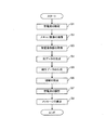
次に、前述のX線診断装置1が行う断層画像撮像用の管電流調整処理について説明する。制御部4aは各種プログラム及び各種データに基づき、管電流設定部11、純生データ生成部12、閾値設定部13及び管電流調整部14などの各部を用いて断層画像撮像用の管電流調整処理を実行する。
Next, tube current adjustment processing for tomographic imaging performed by the above-described X-ray
図3に示すように、まず、操作部4dに対するユーザの入力操作に応じて、管電流が設定される(ステップS1)。このステップS1では、例えば、ユーザが操作部4dを入力操作してSD(標準偏差)を設定した場合には、AEC(Auto Exposure Control)により自動的に管電流値が設定される。あるいは、ユーザが操作部4dを操作して管電流を直接入力した場合には、その入力値が管電流値として設定される。このように管電流値が設定されると、その設定された管電流値に関する管電流情報が記憶部4cに記憶される。
As shown in FIG. 3, first, a tube current is set in accordance with a user input operation to the
ステップS1の処理後、設定された管電流に基づいてスキャノ画像が撮像される(ステップS2)。このステップS2では、例えば、スキャノ画像が0度(平面位置)と90度(側面位置)のビュー角度位置で撮像され、記憶部4cに記憶される。このとき、照射野は最大(例えば、512ピクセル×512ピクセル)にされている。
After the process in step S1, a scano image is captured based on the set tube current (step S2). In this step S2, for example, a scanogram is captured at view angle positions of 0 degrees (plane position) and 90 degrees (side position) and stored in the
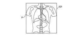
0度の平面位置では、天板2a上の被検体Pの上面にX線が照射されてその被検体Pを透過したX線が検出され、図4に示すように、被検体Pの平面のスキャノ画像として平面画像G1が撮像される。この平面画像G1は、AP方向(前後方向)のスキャノ画像と呼ばれる。また、90度の側面位置では、天板2a上の被検体Pの側面にX線が照射されてその被検体Pを透過したX線が検出され、図5に示すように、被検体Pの側面のスキャノ画像として側面画像G2が撮像される。この側面画像G2は、LR方向(左右方向)のスキャノ画像と呼ばれる。
At the 0-degree plane position, X-rays are detected by irradiating the upper surface of the subject P on the
図3に戻り、ステップS2の処理後、記憶部4cから管電流情報が読み込まれて取得され(ステップS3)、その後、スキャノ画像から生データが生成される(ステップS4)。このステップS4では、図6に示すように、ステップS2で撮像されたスキャノ画像(平面画像G1)の一ラインL1ごとに、生データであるX線量分布データが生成される。
Returning to FIG. 3, after the process of step S2, tube current information is read and acquired from the
例えば、一ラインごとにスキャノ画像データが逆変換され、さらに、ピクセルスケール(例えば、512ピクセル)がX線検出器3eのチャンネルスケール(例えば、900)に戻され、図7に示すような生データD1、すなわちX線量分布データ(カウント数分布データ)が生成される。このように、一ラインごとにピクセルごとのCT値がチャンネルごとのX線量(カウント数)に変換され、スキャノ画像から生データD1が生成される。なお、スキャノ画像としては、平面画像G1及び側面画像G2のどちらか一方又は両方を用いることが可能である。
For example, the scano image data is inversely transformed for each line, and the pixel scale (for example, 512 pixels) is returned to the channel scale (for example, 900) of the
図3に戻り、ステップS4の処理後、生成された生データから純生データが生成される(ステップS5)。このステップS5では、ステップS3で取得された管電流情報及びスキャン条件(例えば、管電圧や回転スピード、FOV(有効視野)など)が用いられ、純生データが生成される。 Returning to FIG. 3, after the process of step S4, pure raw data is generated from the generated raw data (step S5). In step S5, pure raw data is generated using the tube current information and the scan conditions (for example, tube voltage, rotation speed, FOV (effective field of view), etc.) acquired in step S3.
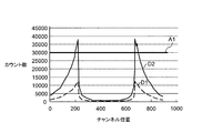
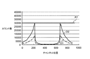
例えば、図8に示すように、生データD1が3倍されて純生データD2が生成される。このときの係数は、管電流情報及びスキャン条件に基づいて、X線検出器3eがスキャノ画像撮像時に実際に受けたX線の線量分布を示す純生データD2が得られるように決定される。
For example, as shown in FIG. 8, the raw data D1 is tripled to generate pure raw data D2. The coefficient at this time is determined on the basis of the tube current information and the scanning conditions so that pure raw data D2 indicating the X-ray dose distribution actually received by the
図3に戻り、ステップS5の処理後、生成された純生データに対する閾値が設定される(ステップS6)。このステップS6では、図9に示すように、閾値としてオーバーフローアーチファクトが出る下限値A1が設定される。このとき、下限値A1は、例えば、データ収集部3fのカウント容量(積算容量)の最大値である30000に設定される。この下限値A1はデータ収集部3fのカウント容量から自動的に設定されるが、これに限るものではなく、例えば、操作部4dに対するユーザの入力操作に応じて予め設定されていても良い。
Returning to FIG. 3, after the process of step S5, a threshold for the generated pure raw data is set (step S6). In step S6, as shown in FIG. 9, a lower limit value A1 at which an overflow artifact is generated is set as a threshold value. At this time, the lower limit value A1 is set to 30000 which is the maximum value of the count capacity (integrated capacity) of the
図3に戻り、ステップS6の処理後、純生データ内のX線量(カウント数)及び前述の閾値に基づいて、管電流が調整される(ステップS7)。このステップS7では、図10に示すように、純生データD2内のX線量(カウント数)が前述の下限値A1より小さくなるように純生データD2が変更されると、これに応じて管電流が調整される。この純生データD2の変更処理は前述の一ラインごとに行われる。 Returning to FIG. 3, after the process of step S6, the tube current is adjusted based on the X-ray dose (count number) in the pure raw data and the above-described threshold (step S7). In this step S7, as shown in FIG. 10, when the pure raw data D2 is changed so that the X-ray dose (count number) in the pure raw data D2 becomes smaller than the aforementioned lower limit value A1, the tube current is changed accordingly. Adjusted. This change process of the pure raw data D2 is performed for each line described above.
例えば、ステップS5において生成された純生データD2内のX線量(カウント数)は前述の下限値A1を超えているため(図9参照)、ステップS7では、純生データD2内のX線量が前述の下限値A1より小さくなるように係数が3倍から2.5倍に変更される(図10参照)。これに応じて、管電流値も自動的に変更される。例えば、最初、係数が3であり、管電流値は一度300mAとされるが、係数が3倍から2.5倍に変更されると、これに応じて250mAに変更される。これにより、断層画像を撮像する場合には、前述のような調整後の管電流値で撮像が行われるため、オーバーフローアーチファクトが発生することがなく、画質が良い断層画像を得ることができる。 For example, since the X-ray dose (count) in the pure raw data D2 generated in step S5 exceeds the aforementioned lower limit A1 (see FIG. 9), in step S7, the X-ray dose in the pure raw data D2 The coefficient is changed from 3 times to 2.5 times so as to be smaller than the lower limit value A1 (see FIG. 10). In response to this, the tube current value is also automatically changed. For example, at first, the coefficient is 3, and the tube current value is once set to 300 mA, but when the coefficient is changed from 3 times to 2.5 times, it is changed to 250 mA accordingly. As a result, when a tomographic image is captured, since the imaging is performed with the adjusted tube current value as described above, an overflow artifact does not occur, and a high-quality tomographic image can be obtained.
図3に戻り、ステップS7の処理後、管電流を変更した旨を報知するメッセージが表示される(ステップS8)。このステップS8では、図11に示すように、「mAを最適化しました。設定mA値を確認してください。」という内容を示すメッセージM1が表示部4eにより表示される。これにより、ユーザはメッセージM1を見て、管電流が自動調整により最適化されたことを認識することができる。なお、自動調整が行われた際に前述のようなメッセージM1が表示されない場合には、ユーザは一度設定した管電流値が勝手に変わってしまったという認識を持つことになる。このため、ユーザは、再度、管電流値を設定したり、あるいは、装置故障が発生したと考えたりしてしまう。
Returning to FIG. 3, after the process of step S7, a message notifying that the tube current has been changed is displayed (step S8). In step S8, as shown in FIG. 11, a message M1 indicating the content of “mA is optimized. Check the set mA value” is displayed on the
ここで、ステップS6において、閾値としては、他のアーチファクト、例えば、図12に示すように、ダークバンドアーチファクトが出る上限値A2が設定されても良い。この上限値A2は、操作部4dに対するユーザの入力操作に応じて予め設定されている。ダークバンドアーチファクトが出る上限値A2が設定された場合、ステップS7では、前述と逆に、純生データD2内のX線量(カウント数)が前述の上限値A2より大きくなるように純生データD2が変更される(図12中の二点鎖線が変更前の純生データD2であり、実線が変更後の純生データD2である)。
Here, in step S6, as the threshold value, another artifact, for example, as shown in FIG. 12, an upper limit value A2 at which a dark band artifact is generated may be set. This upper limit value A2 is set in advance according to a user input operation to the
なお、ステップS6では、閾値として、オーバーフローアーチファクト及びダークバンドアーチファクトのどちらか一方の閾値(下限値A1又は上限値A2)が設定されれば良い。これは、純生データの波形が、オーバーフローアーチファクト及びダークバンドアーチファクトのどちらか一方の発生に偏るためである。 In step S6, any one of the overflow artifact and the dark band artifact (lower limit value A1 or upper limit value A2) may be set as the threshold value. This is because the waveform of pure raw data is biased toward the occurrence of either overflow artifacts or dark band artifacts.
また、ステップS7において、管電流の自動調整を実行しない、すなわち純生データの変更を実行しないような場合には、純生データ内のX線量(カウント数)が下限値A1以上であるとき(図9参照)、オーバーフローアーチファクトが発生する可能性がある旨を報知する警告メッセージを表示部4eにより表示するようにしても良い。これにより、ユーザは警告メッセージを見て、オーバーフローアーチファクトが発生する可能性があることを認識し、管電流を変更することができる。
In step S7, when the automatic adjustment of the tube current is not executed, that is, when the pure raw data is not changed, the X-ray dose (count number) in the pure raw data is equal to or higher than the lower limit value A1 (FIG. 9). For example, a warning message for notifying that an overflow artifact may occur may be displayed on the
また、ステップS6において、ダークバンドアーチファクトが出る上限値A2を設定し、ステップS7において、管電流の自動調整を実行しない、すなわち純生データの変更を実行しないような場合には、純生データ内のX線量(カウント数)が上限値A2以下であるとき(図12参照)、ダークバンドアーチファクトが発生する可能性がある旨を報知する警告メッセージを表示部4eにより表示するようにしても良い。これにより、前述と同様に、ユーザは警告メッセージを見て、ダークバンドアーチファクトが発生する可能性があることを認識し、管電流を変更することができる。
In step S6, an upper limit value A2 at which a dark band artifact is generated is set. In step S7, when automatic adjustment of the tube current is not performed, that is, when the change of the pure raw data is not performed, X in the pure raw data is set. When the dose (count number) is equal to or lower than the upper limit value A2 (see FIG. 12), a warning message for notifying that a dark band artifact may occur may be displayed on the
以上説明したように、本実施形態によれば、スキャノ画像(例えば、平面画像G1や側面画像G2など)から、X線の線量分布を示す純生データが生成され、その生成された純生データに対して閾値が設定される。さらに、生成された純生データ内のX線量と前述の閾値との比較に応じ、被検体Pの断層画像を撮像する場合の管電流が調整される。これにより、管電流は、装置性能上の最大値及び最小値の範囲内で調整されたものではなく、アーチファクトが発生しない範囲内で調整されたものとなる。このため、オーバーフローアーチファクトやダークバンドアーチファクトなどのアーチファクトの発生を抑え、断層画像の画質を向上させることができる。 As described above, according to the present embodiment, pure raw data indicating an X-ray dose distribution is generated from a scanogram (for example, a planar image G1 or a side image G2), and the generated pure raw data is The threshold is set. Furthermore, the tube current in the case of capturing a tomographic image of the subject P is adjusted according to the comparison between the X-ray dose in the generated pure raw data and the above-described threshold value. As a result, the tube current is not adjusted within the range of the maximum and minimum values in terms of device performance, but is adjusted within the range where no artifacts occur. For this reason, generation | occurrence | production of artifacts, such as an overflow artifact and a dark band artifact, can be suppressed, and the image quality of a tomographic image can be improved.
また、被検体Pの断層画像を撮像する場合の管電流を調整したことを報知するメッセージを表示することによって、ユーザはメッセージを見て、管電流が自動的に変更されて最適化されたことを認識することができる。例えば、ユーザが、一度設定した管電流値が勝手に変わってしまったと思い、再度、管電流値を設定したり、あるいは、装置故障が発生したと考えたりするようなことを防止することが可能である。 In addition, by displaying a message notifying that the tube current has been adjusted when capturing a tomographic image of the subject P, the user saw the message and the tube current was automatically changed and optimized. Can be recognized. For example, it is possible to prevent the user from thinking that the tube current value once set has changed without permission and setting the tube current value again or thinking that a device failure has occurred. It is.
また、閾値としてオーバーフローアーチファクトが出る下限値A1を設定し、純生データ内のX線量がその下限値A1より小さくなるように、被検体Pの断層画像を撮像する場合の管電流を調整することから、オーバーフローアーチファクトの発生を抑えることが可能となるので、断層画像の画質を確実に向上させることができる。 Further, the lower limit value A1 at which an overflow artifact is generated as a threshold value is set, and the tube current when the tomographic image of the subject P is imaged is adjusted so that the X-ray dose in the pure raw data is smaller than the lower limit value A1. Since the occurrence of overflow artifacts can be suppressed, the image quality of tomographic images can be reliably improved.
また、閾値としてダークバンドアーチファクトが出る上限値A2を設定し、純生データ内のX線量がその上限値A2より大きくなるように、被検体Pの断層画像を撮像する場合の管電流を調整することから、ダークバンドアーチファクトの発生を抑えることが可能となるので、断層画像の画質を確実に向上させることができる。 In addition, an upper limit value A2 at which dark band artifacts appear is set as a threshold value, and the tube current when the tomographic image of the subject P is captured so that the X-ray dose in the pure raw data is larger than the upper limit value A2. Therefore, the occurrence of dark band artifacts can be suppressed, so that the image quality of the tomographic image can be improved with certainty.
なお、前述の実施形態においては、画像処理部4bにより生成されたスキャノ画像から純生データを生成しているが、これに限るものではなく、画像処理部4bによりスキャノ画像を生成する途中に生じる生データから直接、純生データを生成するようにしても良い。このとき、生データはスキャノ画像を生成する途中に記憶部4cに記憶されており、純生データを生成する際に、その記憶部4bから読み出されて用いられる。
In the above-described embodiment, pure raw data is generated from the scano image generated by the
以上、本発明のいくつかの実施形態を説明したが、これらの実施形態は、例として提示したものであり、発明の範囲を限定することは意図していない。これら新規な実施形態は、その他の様々な形態で実施されることが可能であり、発明の要旨を逸脱しない範囲で、種々の省略、置き換え、変更を行うことができる。これら実施形態やその変形は、発明の範囲や要旨に含まれるとともに、特許請求の範囲に記載された発明とその均等の範囲に含まれる。 As mentioned above, although some embodiment of this invention was described, these embodiment is shown as an example and is not intending limiting the range of invention. These novel embodiments can be implemented in various other forms, and various omissions, replacements, and changes can be made without departing from the scope of the invention. These embodiments and modifications thereof are included in the scope and gist of the invention, and are included in the invention described in the claims and the equivalents thereof.
1 X線診断装置
3c1 X線管
3e X線検出器
3f データ収集部
4b 画像処理部
4e 表示部
11 管電流設定部
12 純生データ生成部
13 閾値設定部
14 管電流調整部
A1 下限値
A2 上限値
D2 純生データ
G1 平面画像
G2 側面画像
M1 メッセージ
DESCRIPTION OF
Claims (6)
前記管電流設定部により設定された前記位置決め画像を撮像する場合の管電流に基づいて前記被検体に対してX線を出射するX線管と、
前記X線管により出射されて前記被検体を透過したX線を検出するX線検出器と、
前記X線検出器により検出された前記X線の透過データを収集するデータ収集部と、
前記データ収集部により収集された前記透過データから位置決め画像を生成する画像処理部と、
前記画像処理部により生成された前記位置決め画像又は前記画像処理部により前記位置決め画像を生成する途中に生じる第1データから、X線の線量分布を示す第2データを生成するデータ生成部と、
前記データ生成部により生成された前記第2データに対して閾値を設定する閾値設定部と、
前記データ生成部により生成された前記第2データ内のX線量と前記閾値設定部により設定された前記閾値との比較に応じ、前記被検体の断層画像を撮像する場合の管電流を調整する管電流調整部と、
を備えることを特徴とするX線診断装置。 A tube current setting unit for setting a tube current when imaging a positioning image of a subject;
An X-ray tube that emits X-rays to the subject based on a tube current when capturing the positioning image set by the tube current setting unit;
An X-ray detector that detects X-rays emitted by the X-ray tube and transmitted through the subject;
A data collection unit for collecting transmission data of the X-rays detected by the X-ray detector;
An image processing unit that generates a positioning image from the transmission data collected by the data collection unit;
A data generation unit that generates second data indicating a dose distribution of X-rays from the positioning image generated by the image processing unit or first data generated in the middle of generating the positioning image by the image processing unit;
A threshold setting unit that sets a threshold for the second data generated by the data generation unit;
A tube that adjusts the tube current when capturing a tomographic image of the subject in accordance with a comparison between the X-ray dose in the second data generated by the data generation unit and the threshold set by the threshold setting unit A current adjustment unit;
An X-ray diagnostic apparatus comprising:
前記管電流調整部は、前記データ生成部により生成された前記第2データ内のX線量が、前記閾値設定部により設定された前記下限値より小さくなるように、前記被検体の断層画像を撮像する場合の管電流を調整することを特徴とする請求項1又は2記載のX線診断装置。 The threshold setting unit sets a lower limit value at which artifacts are generated as the threshold,
The tube current adjustment unit captures a tomographic image of the subject so that an X-ray dose in the second data generated by the data generation unit is smaller than the lower limit value set by the threshold setting unit. The X-ray diagnostic apparatus according to claim 1, wherein the tube current is adjusted in the case of performing.
前記管電流調整部は、前記データ生成部により生成された前記第2データ内のX線量が、前記閾値設定部により設定された前記上限値より大きくなるように、前記被検体の断層画像を撮像する場合の管電流を調整することを特徴とする請求項1又は2記載のX線診断装置。 The threshold setting unit sets an upper limit value at which an artifact is generated as the threshold,
The tube current adjustment unit captures a tomographic image of the subject such that an X-ray dose in the second data generated by the data generation unit is larger than the upper limit value set by the threshold setting unit. The X-ray diagnostic apparatus according to claim 1, wherein the tube current is adjusted in the case of performing.
前記管電流調整部は、前記データ生成部により生成された前記第2データ内のX線量が、前記閾値設定部により設定された前記下限値より小さく、又は、前記閾値設定部により設定された前記上限値より大きくなるように、前記被検体の断層画像を撮像する場合の管電流を調整することを特徴とする請求項1又は2記載のX線診断装置。 The threshold setting unit sets, as the threshold, a lower limit value at which the first artifact appears and an upper limit value at which the second artifact appears,
The tube current adjustment unit has an X-ray dose in the second data generated by the data generation unit smaller than the lower limit value set by the threshold setting unit or set by the threshold setting unit The X-ray diagnostic apparatus according to claim 1, wherein a tube current in the case of capturing a tomographic image of the subject is adjusted to be larger than an upper limit value.
Priority Applications (3)
| Application Number | Priority Date | Filing Date | Title |
|---|---|---|---|
| JP2012025848A JP6129474B2 (en) | 2012-02-09 | 2012-02-09 | X-ray diagnostic equipment |
| CN201310047327.XA CN103239252B (en) | 2012-02-09 | 2013-02-06 | The method of radiographic apparatus and control radiographic apparatus |
| US13/760,539 US9050058B2 (en) | 2012-02-09 | 2013-02-06 | X-ray diagnostic system and X-ray diagnostic method |
Applications Claiming Priority (1)
| Application Number | Priority Date | Filing Date | Title |
|---|---|---|---|
| JP2012025848A JP6129474B2 (en) | 2012-02-09 | 2012-02-09 | X-ray diagnostic equipment |
Publications (3)
| Publication Number | Publication Date |
|---|---|
| JP2013158630A JP2013158630A (en) | 2013-08-19 |
| JP2013158630A5 JP2013158630A5 (en) | 2015-03-05 |
| JP6129474B2 true JP6129474B2 (en) | 2017-05-17 |
Family
ID=48919370
Family Applications (1)
| Application Number | Title | Priority Date | Filing Date |
|---|---|---|---|
| JP2012025848A Active JP6129474B2 (en) | 2012-02-09 | 2012-02-09 | X-ray diagnostic equipment |
Country Status (3)
| Country | Link |
|---|---|
| US (1) | US9050058B2 (en) |
| JP (1) | JP6129474B2 (en) |
| CN (1) | CN103239252B (en) |
Families Citing this family (13)
| Publication number | Priority date | Publication date | Assignee | Title |
|---|---|---|---|---|
| DE102012216850B3 (en) * | 2012-09-20 | 2014-02-13 | Siemens Aktiengesellschaft | Method for planning support and computed tomography device |
| MX2016002536A (en) | 2013-08-28 | 2016-06-17 | Alfred E Mann Inst Biomed Eng | Minimally obstructive retractor for vaginal repairs. |
| WO2015071798A1 (en) * | 2013-11-18 | 2015-05-21 | Koninklijke Philips N.V. | One or more two dimensional (2d) planning projection images based on three dimensional (3d) pre-scan image data |
| JP6381966B2 (en) * | 2014-05-14 | 2018-08-29 | キヤノンメディカルシステムズ株式会社 | Medical diagnostic imaging equipment |
| CN104302081B (en) * | 2014-09-24 | 2017-06-16 | 沈阳东软医疗系统有限公司 | The control method and equipment of heater current in a kind of CT bulbs |
| JP6771879B2 (en) * | 2014-10-31 | 2020-10-21 | キヤノンメディカルシステムズ株式会社 | X-ray computed tomography equipment |
| KR20160139294A (en) * | 2015-05-27 | 2016-12-07 | 삼성전자주식회사 | Apparatus and method for photographing medical image |
| JP6681689B2 (en) * | 2015-10-16 | 2020-04-15 | ジーイー・メディカル・システムズ・グローバル・テクノロジー・カンパニー・エルエルシー | Radiation tomography apparatus and program |
| JP6849521B2 (en) * | 2017-05-01 | 2021-03-24 | キヤノン電子管デバイス株式会社 | X-ray system and X-ray tube inspection method |
| JP7258473B2 (en) | 2018-05-01 | 2023-04-17 | キヤノンメディカルシステムズ株式会社 | X-ray CT device and imaging condition management device |
| JP7144292B2 (en) * | 2018-11-27 | 2022-09-29 | キヤノンメディカルシステムズ株式会社 | MEDICAL IMAGE PROCESSING APPARATUS AND MEDICAL IMAGE PROCESSING METHOD |
| JP7309988B2 (en) * | 2018-11-27 | 2023-07-18 | キヤノンメディカルシステムズ株式会社 | MEDICAL IMAGE PROCESSING APPARATUS AND MEDICAL IMAGE PROCESSING METHOD |
| CN113797448A (en) * | 2020-06-11 | 2021-12-17 | 中硼(厦门)医疗器械有限公司 | Irradiation parameter selection device and use method thereof |
Family Cites Families (13)
| Publication number | Priority date | Publication date | Assignee | Title |
|---|---|---|---|---|
| JP4075166B2 (en) * | 1998-11-30 | 2008-04-16 | 松下電器産業株式会社 | X-ray board inspection equipment |
| JP3950612B2 (en) | 2000-02-08 | 2007-08-01 | ジーイー横河メディカルシステム株式会社 | X-ray CT system |
| JP4532005B2 (en) * | 2001-03-09 | 2010-08-25 | 株式会社日立メディコ | X-ray CT apparatus and image display method thereof |
| JP4309631B2 (en) * | 2001-10-22 | 2009-08-05 | 株式会社東芝 | X-ray computer tomography equipment |
| US7054406B2 (en) * | 2002-09-05 | 2006-05-30 | Kabushiki Kaisha Toshiba | X-ray CT apparatus and method of measuring CT values |
| JP2004325183A (en) | 2003-04-23 | 2004-11-18 | M & C:Kk | Radiation detection method, radiation detector, and radiation imaging system with this detector loaded thereon |
| US7149276B2 (en) * | 2004-07-14 | 2006-12-12 | Kabushiki Kaisha Toshiba | System, method, and computer program product that corrects measured data |
| US7215733B2 (en) * | 2004-07-23 | 2007-05-08 | Kabushiki Kaisha Toshiba | X-ray computed tomography apparatus |
| EP1731100B9 (en) * | 2005-06-06 | 2013-01-23 | Kabushiki Kaisha Toshiba | Medical image display apparatus and medical image display system |
| JP2009050531A (en) | 2007-08-28 | 2009-03-12 | Konica Minolta Medical & Graphic Inc | Radiation image capturing system |
| JP5675117B2 (en) * | 2009-02-17 | 2015-02-25 | 株式会社東芝 | X-ray CT apparatus and control program for X-ray CT apparatus |
| JP5514450B2 (en) * | 2009-02-23 | 2014-06-04 | 株式会社日立メディコ | X-ray CT system |
| JP5537138B2 (en) | 2009-12-10 | 2014-07-02 | 株式会社東芝 | X-ray CT apparatus and control program thereof |
-
2012
- 2012-02-09 JP JP2012025848A patent/JP6129474B2/en active Active
-
2013
- 2013-02-06 US US13/760,539 patent/US9050058B2/en active Active
- 2013-02-06 CN CN201310047327.XA patent/CN103239252B/en active Active
Also Published As
| Publication number | Publication date |
|---|---|
| JP2013158630A (en) | 2013-08-19 |
| US9050058B2 (en) | 2015-06-09 |
| CN103239252B (en) | 2015-08-12 |
| CN103239252A (en) | 2013-08-14 |
| US20130208853A1 (en) | 2013-08-15 |
Similar Documents
| Publication | Publication Date | Title |
|---|---|---|
| JP6129474B2 (en) | X-ray diagnostic equipment | |
| JP6289223B2 (en) | X-ray computed tomography system | |
| JP6571313B2 (en) | Medical image diagnostic apparatus and control method | |
| US10219756B2 (en) | Radiography device, radiography method, and radiography program | |
| JP5727277B2 (en) | X-ray CT system | |
| JP2013215392A (en) | X-ray diagnostic apparatus and method for controlling the x-ray diagnostic apparatus | |
| JP6615439B2 (en) | X-ray CT system | |
| JP5308862B2 (en) | Medical bed apparatus and medical image photographing apparatus | |
| US20140048713A1 (en) | System and method for reducing grid line image artifacts | |
| JP7086756B2 (en) | Medical diagnostic imaging equipment | |
| JP6125206B2 (en) | X-ray diagnostic imaging equipment | |
| JP6523451B2 (en) | Radiation detector and X-ray CT apparatus equipped with the same | |
| JP2020049059A (en) | Medical image processing apparatus and method | |
| JP2013192750A (en) | X-ray diagnostic apparatus and control method thereof | |
| JP2013172881A (en) | Image processing device and method | |
| JP2020022579A (en) | X-ray computed tomography apparatus | |
| JP7206163B2 (en) | X-ray CT apparatus, medical information processing apparatus, and medical information processing program | |
| JP7305334B2 (en) | X-ray diagnostic system and reconstruction processing system | |
| JP7062514B2 (en) | X-ray CT device and X-ray tube control device | |
| JP6506583B2 (en) | Radiation tomography apparatus, image generation apparatus and program | |
| JP2024030533A (en) | Photon counting type X-ray image diagnostic device and method for generating calibration data for pile-up correction | |
| US20190336089A1 (en) | X-ray computed tomography apparatus and imaging condition management apparatus | |
| JP2023035485A (en) | X-ray ct apparatus | |
| JP6162324B2 (en) | Radiographic imaging system, radiographic imaging method, and radiographic imaging program | |
| JP2018008049A (en) | X-ray CT apparatus |
Legal Events
| Date | Code | Title | Description |
|---|---|---|---|
| A521 | Request for written amendment filed |
Free format text: JAPANESE INTERMEDIATE CODE: A523 Effective date: 20150120 |
|
| A621 | Written request for application examination |
Free format text: JAPANESE INTERMEDIATE CODE: A621 Effective date: 20150120 |
|
| RD01 | Notification of change of attorney |
Free format text: JAPANESE INTERMEDIATE CODE: A7421 Effective date: 20150703 |
|
| A977 | Report on retrieval |
Free format text: JAPANESE INTERMEDIATE CODE: A971007 Effective date: 20151023 |
|
| A131 | Notification of reasons for refusal |
Free format text: JAPANESE INTERMEDIATE CODE: A131 Effective date: 20151104 |
|
| A521 | Request for written amendment filed |
Free format text: JAPANESE INTERMEDIATE CODE: A523 Effective date: 20151225 |
|
| A131 | Notification of reasons for refusal |
Free format text: JAPANESE INTERMEDIATE CODE: A131 Effective date: 20160517 |
|
| A711 | Notification of change in applicant |
Free format text: JAPANESE INTERMEDIATE CODE: A711 Effective date: 20160527 |
|
| A521 | Request for written amendment filed |
Free format text: JAPANESE INTERMEDIATE CODE: A523 Effective date: 20160715 |
|
| A02 | Decision of refusal |
Free format text: JAPANESE INTERMEDIATE CODE: A02 Effective date: 20161108 |
|
| A521 | Request for written amendment filed |
Free format text: JAPANESE INTERMEDIATE CODE: A523 Effective date: 20170208 |
|
| A911 | Transfer to examiner for re-examination before appeal (zenchi) |
Free format text: JAPANESE INTERMEDIATE CODE: A911 Effective date: 20170215 |
|
| TRDD | Decision of grant or rejection written | ||
| A01 | Written decision to grant a patent or to grant a registration (utility model) |
Free format text: JAPANESE INTERMEDIATE CODE: A01 Effective date: 20170314 |
|
| A61 | First payment of annual fees (during grant procedure) |
Free format text: JAPANESE INTERMEDIATE CODE: A61 Effective date: 20170412 |
|
| R150 | Certificate of patent or registration of utility model |
Ref document number: 6129474 Country of ref document: JP Free format text: JAPANESE INTERMEDIATE CODE: R150 |
|
| S533 | Written request for registration of change of name |
Free format text: JAPANESE INTERMEDIATE CODE: R313533 |
|
| R350 | Written notification of registration of transfer |
Free format text: JAPANESE INTERMEDIATE CODE: R350 |