JP4309631B2 - X-ray computer tomography equipment - Google Patents
X-ray computer tomography equipment Download PDFInfo
- Publication number
- JP4309631B2 JP4309631B2 JP2002276917A JP2002276917A JP4309631B2 JP 4309631 B2 JP4309631 B2 JP 4309631B2 JP 2002276917 A JP2002276917 A JP 2002276917A JP 2002276917 A JP2002276917 A JP 2002276917A JP 4309631 B2 JP4309631 B2 JP 4309631B2
- Authority
- JP
- Japan
- Prior art keywords
- ray
- tube current
- tube
- tomography apparatus
- transmittance
- Prior art date
- Legal status (The legal status is an assumption and is not a legal conclusion. Google has not performed a legal analysis and makes no representation as to the accuracy of the status listed.)
- Expired - Fee Related
Links
- 238000002591 computed tomography Methods 0.000 title claims description 19
- 238000001514 detection method Methods 0.000 claims description 25
- 238000003491 array Methods 0.000 claims description 13
- 230000001678 irradiating effect Effects 0.000 claims description 2
- 238000002834 transmittance Methods 0.000 description 73
- 238000010586 diagram Methods 0.000 description 17
- 238000000034 method Methods 0.000 description 8
- 230000008859 change Effects 0.000 description 7
- 238000012986 modification Methods 0.000 description 6
- 230000004048 modification Effects 0.000 description 6
- 238000006243 chemical reaction Methods 0.000 description 5
- 238000003384 imaging method Methods 0.000 description 4
- 241001669679 Eleotris Species 0.000 description 3
- 239000000470 constituent Substances 0.000 description 3
- 238000013480 data collection Methods 0.000 description 3
- 230000000694 effects Effects 0.000 description 3
- 210000001015 abdomen Anatomy 0.000 description 2
- 210000004072 lung Anatomy 0.000 description 2
- 238000007781 pre-processing Methods 0.000 description 2
- 230000008569 process Effects 0.000 description 2
- 238000012545 processing Methods 0.000 description 2
- 238000012935 Averaging Methods 0.000 description 1
- OAICVXFJPJFONN-UHFFFAOYSA-N Phosphorus Chemical compound [P] OAICVXFJPJFONN-UHFFFAOYSA-N 0.000 description 1
- 230000005540 biological transmission Effects 0.000 description 1
- 210000000988 bone and bone Anatomy 0.000 description 1
- 238000011161 development Methods 0.000 description 1
- 238000005516 engineering process Methods 0.000 description 1
- 230000006872 improvement Effects 0.000 description 1
- 239000011159 matrix material Substances 0.000 description 1
- 230000007246 mechanism Effects 0.000 description 1
- 210000000056 organ Anatomy 0.000 description 1
- 230000002093 peripheral effect Effects 0.000 description 1
- 230000005855 radiation Effects 0.000 description 1
- 239000004065 semiconductor Substances 0.000 description 1
- 230000007480 spreading Effects 0.000 description 1
- 238000012546 transfer Methods 0.000 description 1
- 238000004846 x-ray emission Methods 0.000 description 1
Images


Classifications
-
- A—HUMAN NECESSITIES
- A61—MEDICAL OR VETERINARY SCIENCE; HYGIENE
- A61B—DIAGNOSIS; SURGERY; IDENTIFICATION
- A61B6/00—Apparatus for radiation diagnosis, e.g. combined with radiation therapy equipment
- A61B6/02—Devices for diagnosis sequentially in different planes; Stereoscopic radiation diagnosis
- A61B6/03—Computerised tomographs
- A61B6/032—Transmission computed tomography [CT]
-
- A—HUMAN NECESSITIES
- A61—MEDICAL OR VETERINARY SCIENCE; HYGIENE
- A61B—DIAGNOSIS; SURGERY; IDENTIFICATION
- A61B6/00—Apparatus for radiation diagnosis, e.g. combined with radiation therapy equipment
- A61B6/54—Control of apparatus or devices for radiation diagnosis
- A61B6/542—Control of apparatus or devices for radiation diagnosis involving control of exposure
Description
【0001】
【発明の属する技術分野】
本発明は、X線管とマルチスライス型X線検出器とを備えるX線コンピュータトモグラフィ装置に関する。
【0002】
【従来の技術】
近年のX線コンピュータ断層撮影装置に関する重要な課題の一は、画質向上と低被曝化との両立である。被検体に照射するX線の強度を高くすると、画質は向上する。被検体に照射するX線の強度を低くすると、画質は低下する。
【0003】
従来の装置では、ヘリカルスキャン中に照射X線強度は一定値に維持される。しかし、最近では、被検体の部位に応じて変化するX線透過率に従って、X線強度を変化させる提案がなされている。多くの提案では、スキャノグラム上のある一点の値に従って、X線強度を変化させる。スキャノグラムは、周知のとおり、スキャン計画のために収集される透過X線の平面的な強度分布である。
【0004】
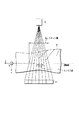
スキャノグラムデータを収集するために、図1(a)、図2(a)に示すように、X線管10はある回転角度で固定される。天板2aは一定速度で移動される。この期間、X線検出器11から一定周期で信号が繰り返し読出される。
【0005】
このX線強度制御は、図1(b)に示すシングルスライススキャンでは有効に作用する。しかし、図2(b)に示すように、マルチスライススキャン(ボリュームスキャンともいう)では、X線強度は、十分に最適化されることができない。その最大の理由は、図1(c)、図2(c)に示すように、マルチスライススキャンは、スキャノグラムデータ収集時のスライス幅T1よりも広いスライス幅T2を持つ広範囲のデータを一度に収集することにある。
【0006】
【特許文献1】
特開2000−262512号公報
【0007】
【特許文献2】
実用新案登録第2605048号公報
【0008】
【特許文献3】
特開平10−295681号公報
【0009】
【特許文献4】
特開平08−206107公報
【0010】
【特許文献5】
特開平09−199292号公報
【0011】
【特許文献6】
特公平06−036793号公報
【0012】
【発明が解決しようとする課題】
本発明の目的は、マルチスライススキャンにおいて、X線強度をより最適化することにある。
【0013】
【課題を解決するための手段】
本発明のある局面によるX線コンピュータトモグラフィ装置は、被検体に照射するためのX線を発生するX線管と、前記X線管に印加するための高電圧を発生する高電圧発生器と、前記被検体を透過したX線を検出するために複数のX線検出素子列を有するX線検出器と、前記X線検出器の出力に基づいて、スキャノグラムを生成するスキャノグラム生成部と、前記X線検出器の出力に基づいて、画像を再構成する再構成部と、前記スキャノグラムの2次元部分領域内に含まれる複数画素の画素値の最大値又は平均値に基づいて、前記X線管の管電流値を決定する管電流決定部と、前記決定された管電流値に基づいて前記高電圧発生器を制御する制御部とを具備する。
【0014】
【発明の実施の形態】
以下、図面を参照して本発明によるX線コンピュータ断層撮影装置(X線CT装置)の実施例を説明する。なお、X線CT装置には、X線管と放射線検出器とが1体として被検体の周囲を回転する回転/回転(ROTATE/ROTATE)タイプと、リング状に多数の検出素子がアレイされ、X線管のみが被検体の周囲を回転する固定/回転(STATIONARY/ROTATE)タイプ等様々なタイプがあり、いずれのタイプでも本発明を適用可能である。ここでは、現在、主流を占めている回転/回転タイプとして説明する。
【0015】
また、1スライスの断層像データを再構成するには、被検体の周囲1周、約360°分の投影データが、またハーフスキャン法でも180°+ビュー角分の投影データが必要とされる。いずれの再構成方式にも本発明を適用可能である。ここでは、ハーフスキャン法を例に説明する。
【0016】
また、入射X線を電荷に変換するメカニズムは、シンチレータ等の蛍光体でX線を光に変換し更にその光をフォトダイオード等の光電変換素子で電荷に変換する間接変換形と、X線による半導体内の電子正孔対の生成及びその電極への移動すなわち光導電現象を利用した直接変換形とが主流である。X線検出素子としては、それらのいずれの方式を採用してもよいが、ここでは、前者の間接変換形として説明する。
【0017】
また、近年では、X線管とX線検出器との複数のペアを回転リングに搭載したいわゆる多管球型のX線CT装置の製品化が進み、その周辺技術の開発が進んでいる。本発明では、従来からの一管球型のX線CT装置であっても、多管球型のX線CT装置であってもいずれにも適用可能である。ここでは、一管球型として説明する。
【0018】
図3に、本実施例に係るX線コンピュータ断層撮影装置の主要部の構成を示している。ガントリ1の内部には、略円筒形状の回転フレーム12が収容されている。回転フレーム12は、ガントリコントローラ33の制御のもとで、スキャン時には、ガントリ駆動装置25により回転され、スキャノグラムデータ収集時には、ガントリ駆動装置25の制動機能により、所定角度、例えば0°の位置に固定される。回転フレーム12には、X線管10とX線検出器11とが取り付けられている。高電圧発生装置21は、高電圧コントローラ31の制御のもとで、X線管10の陰極陽極間に高電圧(管電圧)を印加する。高電圧発生装置21は、高電圧コントローラ31の制御のもとで、陰極のフィラメントにフィラメント電流を供給する。フィラメント電流に応じて陰極陽極間に流れる管電流が決まる。管電流に応じて照射X線の強度が決まる。
【0019】
X線管10のX線放射窓には、X線を四角錐形に絞るコリメータ22が取り付けられる。コリメータ22の開度は可変である。X線検出器11は、寝台2の天板2a上に載置される被検体Pを挟んでX線管10に対向する。X線検出器11は、図4に示すように、スライス方向に沿って並べられた複数、ここではNのX線検出素子列14を有する。各X線検出素子列14は、チャンネル方向に配列された複数、ここではM個のX線検出素子13を有する。寝台2の天板2aは、寝台コントローラ32の制御のもとで、サーボモータ等の寝台駆動装置2bによりスライス方向に沿って移動される。
【0020】
キャビネット3は、システム全体の動作を制御するシステムコントローラ43、スキャンコントローラ30、前処理ユニット34、データストアリングユニット35、再構成ユニット36、表示プロセッサ37、ディスプレイ38及び入力器(コンソール)39とともに、スキャノグラム生成ユニット43、透過率計算部41、管電流値計算部42を備えている。
【0021】
図5は、透過率計算部41の透過率計算手順を示している。まず、スキャノグラムデータが収集される(S1)。スキャノグラムデータは、本来的には、スキャン範囲や撮影条件等のスキャン計画を立てる際に参照するために収集される。このスキャノグラムデータは、透過率計算のための基礎データとしても使用される。図6(a)に示すように、スキャノグラムデータは、通常、中央の素子列14により収集される。スキャノグラムデータを収集するために、回転フレーム12は例えば0°の位置に固定され、天板2aは、定速で移動される。天板2aが定速で移動している間、X線管10から低い強度を有するX線が連続的に曝射される。X線が連続的に曝射されている間、中央の素子列14から一定の周期で信号が読み出される(図6(b)参照)。信号が読み出される周期と天板2aの移動速度とにより、スキャノグラムのスライス方向に関する分解能が決まる。スキャノグラムのチャンネル方向に関する分解能は、チャンネルピッチにより規定される。1チャンネルが1素子に相当すると仮定すると、チャンネルピッチは素子ピッチ、つまり隣り合う検出素子の中心点間距離に等価である。
【0022】
一定周期で読み出された信号は、データ収集装置24、前処理ユニット34を経由してスキャノグラム生成ユニット43へと送られる。スキャノグラム生成ユニット43では、各チャンネルのデータには、チャンネル番号データと位置センサ25で検出された天板2aのスライス方向の位置データとが関連付けられる。それにより、スキャノグラムデータが生成される。生成されたスキャノグラムデータは、データストアリングユニット35に記憶される。
【0023】
このスキャノグラムの各画素値は、透過X線の強度を表しており、透過X線の強度と、既知の照射X線強度とから、スライス方向の各位置のX線透過率を計算することができる。各位置の透過率は、その位置を中心として2次元領域内に含まれる複数の画素の画素値から計算される。当該2次元領域は、マスクと呼ばれる。
【0024】
透過率計算部41は、入力器39を介して入力されたマスクサイズに関するユーザインストラクションに従って、マスクサイズ(n×m)を設定する(S2)。マスクサイズの入力を支援するために、表示プロセッサ37は、データストアリングユニット35から読み出したスキャノグラムデータに従ってスキャノグラムをディスプレイ38に表示させるとともに、このスキャノグラム上に、マスクフレームをスーパーインポーズする。
【0025】
図7(a)は、ディスプレイ38に表示されたスキャノグラムと、デフォルトのマスクフレームの例を示している。マスクフレームは、デフォルトでは、四角形状を有し、そのマトリクスサイズは、縦がスキャン幅/スライス方向分解能(=N)で決まる画素数、横が検出器10の各列のチャンネル数(=M)に等価な画素数に設定されている。スキャン幅は、図8に示すように、撮影スライス枚数×スライス厚で定義される。撮影スライス枚数とスライス厚とはスキャン計画時にユーザにより設定される。撮影スライス枚数はマルチスライススキャンでは少なくとも2に設定される。スライス厚は、回転中心軸上での1スライスの厚さで定義され、一つの検出素子列14の有感幅の回転中心軸上での換算長の正の整数倍から選択的に指定される。
【0026】
マスクフレームは、ユーザによる入力器39の操作に従って、図7(b)に示すように、2<n<N、且つ2<m<Mの範囲内で、任意に拡大/縮小されることができる。つまり、マスクフレームには、少なくとも2×2の画素が含まれる。また、マスクフレームは、ユーザによる入力器39の操作に従って、図7(c)に示すように、十字形状を含む任意の多角形状に変形されることができる。また、マスクフレームは、ユーザによる入力器39の操作に従って、図7(d)に示すように、楕円又は円形に変形されることができる。
【0027】
マスクサイズが決まった後、透過率計算部41は、図9(a)に示すように、スキャノグラムに対してマスクを開始位置に配置し(S3)、その位置にあるマスクに含まれる複数の画素の画素値を、データストアリングユニット35から選択的に読み出す(S4)。読み出された複数の画素の画素値から、その平均値が計算される(S5)。平均値に代えて、読み出された複数画素の画素値の中からその最大値(又は最小値)が抽出されるようにしてもよい。平均値を計算するか、最大値を抽出するか、最小値を抽出するかは、ユーザにより選択される。なお、平均値が選択された場合、安定した管電流制御が実現され得る。最大値が選択された場合、被曝低減に効果的な管電流制御が実現され得る。最小値が選択された場合、S/Nの向上に効果的な管電流制御が実現され得る。
【0028】
なお、このマスク内の平均値は、換言すると、スキャノグラムの画素値をチャンネル方向に関して平均し、そのチャンネル方向の平均値を、スライス方向に関して移動平均した値に等価である。
【0029】
次に、透過率計算部41で、2次元領域内での平均値(又は最大値或いは最小値)に基づいて、マスクのスライス方向に関する中心位置zに対応する透過率F(z)が次の式に従って計算される。
【0030】
F(z)=log(I0/(I0−I1))
ただし、I0:照射X線強度
I1:透過X線強度
なお、上記では、2次元領域内でのスキャノグラムデータに基づいて管電流値を決定したが、スキャノグラムデータの生成前の段階にある検出器11の出力(生データ(ロウデータ)と呼ばれる)に関する2次元領域の分布に基づいて管電流値を決定するようにしてもよい。ロウデータ、スキャノグラムデータ、ロウデータから得られる各種インデックスデータをX線データと総称する。
【0031】
次に、図9(b)に示すようにマスクが単位距離だけスライス方向に移動され(S8)、S7でマスクが終端位置に達するまで(図9(c)参照)、S4−S6の処理が繰り返される。それにより図10(a)、図10(b)に示すように、X線透過率F(z)のスライス方向に関する離散分布が生成される。なお、上記単位距離は、スキャノグラムのスライス方向に関する分解能と素子列14の幅とのいずれかに初期的に設定される。単位距離はユーザの指示に従って任意の距離に変更可能である。
【0032】
最後に、X線透過率F(z)のスライス方向に関する離散分布から、補間により、X線透過率F(z)のスライス方向に関する連続的な分布(透過率プロファイルという)が生成される(S9)。この透過率プロファイルは、データストアリングユニット35に記憶される。
【0033】
通常、X線透過率F(z)は、胸部よりも肩部や腹部において低くなる。胸部には肺が存在し、肺内部の空気によりその大部分を占められるためX線透過率が高くなるのに対し、肩部には骨部が存在し、又腹部には臓器が存在するためX線透過率が低くなるのである。
【0034】
ここで注意すべき点は、本実施例では、透過率を、チャンネル方向だけでなく、スライス方向にも広がった2次元領域内の透過X線強度の平均値(又は最大値或いは最小値)にもとづて計算したことにある。このことが、シングルスライススキャンに比べて、スライス方向に視野の格段に広いマルチスライススキャンで、好適な管電流制御を実現する。
【0035】
図11には、ヘリカルスキャンにおいて、透過率プロファイルを使った管電流制御の手順を示している。スキャンコントローラ30の制御のもとで、ヘリカルスキャンが開始される(S11)。ヘリカルスキャンでは、天板2aが一定速度で移動され、X線管10が検出器11と共に連続的に回転される。その間、X線が連続的に曝射され、検出器11から一定周期で信号が読み出される。
【0036】
天板2aの位置データが位置センサ25からスキャンコントローラ30に一定周期で次々と供給される(S12)。説明の便宜上、天板2aの位置は、撮影中心位置に等価であると仮定する。撮影中心位置とは、天板2aの移動座標系において、スライス方向(Z軸方向)に広がったX線の中心軸のZ位置である。システムコントローラ43の制御のもとで、位置データと共に透過率読み出し要求がデータストアリングユニット35に出される。データストアリングユニット35から管電流値計算部42に、当該位置に対応するX線透過率データが読み出される(S13)。管電流値計算部42は、読み出されたX線透過率に基づいて、管電流値を計算する(S14)。
【0037】
図12(a)に、一般的なX線透過率F(z)と管電流(Itube)との関係図を示している。同図に示すように、X線透過率F(z)と管電流値(Itube)の関係は、比例関係にあることがある。このような関係図を用いることにより、X線透過率F(z)の値から一義的に管電流(Itube)の値を特定することができる。実際には、X線透過率F(z)と管電流(Itube)との関係を規定する関数式に従って、読み出されたX線透過率F(z)から管電流値(Itube)が計算される。しかし、X線透過率F(z)と管電流値(Itube)との関係を事前に計算し、その計算結果をテーブルとして保持していても良い。その場合、管電流値計算部42は、入力されるX線透過率F(z)に対して、対応する管電流値(Itube)を出力するよう組まれたROMとして構成される。
【0038】
X線透過率F(z)と管電流値(Itube)の関係は、図12(a)に示した比例関係に限定されない。図12(b)に示す指数関係を用いても良い。実際、X線は被検体Pを透過する際、指数関数的に減衰していくので、X線透過率F(z)と管電流(Itube)の関係として、指数曲線(Itube=expFx(z))を用いることにより、より現実に即した形となり、より適切な管電流値(Itube)を求めることができる。図12(c)及び図12(d)に示すように、管電流値(Itube)に、上限値(Itube,max)と下限値(Itube,min)を設定してもよい。それにより、常にX線管の容量の範囲内でX線照射を行うことができることになり、X線管の放電を防止することができる。
【0039】
図11に戻る。スキャンコントローラ30は、決定された管電流値でX線管10の陰極陽極間に電流が流れるように、フィラメント電流を制御する(S15)。S12−S15の処理は、S16でヘリカルスキャンが終了するまで繰り返される。ヘリカルスキャンは、天板位置が、計画されたスキャン範囲の終端位置に達したときに終了される(S17)。
【0040】
図13に示すように、スライス方向に関する透過率F(z)のプロファイルに基づいて管電流Itubeを制御することにより、天板2aの移動に伴って動的に管電流Itubeが変化される。透過率F(z)は、チャンネル方向だけでなく、スライス方向にも広がった2次元領域内の透過X線強度の平均値(又は最大値或いは最小値)に基づいて計算され、その透過率に基づいて管電流を制御している。それにより、シングルスライススキャンに比べて、スライス方向に視野の広いマルチスライススキャンであっても、好適な管電流制御を実現することができる。
【0041】
ここで、管電流(Itube)の制御に、透過X線強度の2次元領域内での平均値を用いた場合と、最大値(又は最小値)を用いた場合の効果の違いについて簡単に述べる。平均値を用いた場合、被検体のX線透過率の突然の変化にも対応することができ、また、極端に酷い画像ノイズやアーチファクト等が発生することがなくなり、該画像ノイズやアーチファクト等を常に均一(ある程度の範囲内)に抑えることができる。一方、最大値(又は最小値)を用いた場合、画像ノイズやアーチファクト等を、より低く抑えることができる。
【0042】
上述では、一方向に対応する1つの透過率プロファイルを使って天板2aのスライス方向移動に応じて動的に管電流を制御することを説明した。スライス方向移動とともに、X線管10の回転角度の変化にも応じて、より精細に管電流を制御するようにしてもよい。そのためには、少なくとも二方向に対応する2つの透過率プロファイルが必要とされる。
【0043】
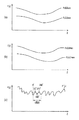
図14に示すように、X線管10が0°の位置に固定されて状態で、スキャノグラムデータが収集される。また、X線管10が90°の位置に固定されて状態で、スキャノグラムデータが収集される。このように2方向からのスキャノグラムデータが収集される。図5の処理により、方向の違う2つのスキャノグラムに基づいて2つの透過率プロファイルFx(z)、Fy(z)が生成される。Fx(z)は、X線管10が0°の位置に対応し、Fy(z)は、X線管10が90°の位置に対応している。図15(a)にはマスク内平均値から求めた透過率プロファイルFx(z)ave、Fy(z)aveを示し、図15(b)にはマスク内最大値から求めた透過率プロファイルFx(z)max、Fy(z)maxを示している。一般に、人体はX方向に関して拉げた形状をしているので、Fy(z)がFx(z)よりも低くなる。いずれを使うかはユーザの選択次第である。
【0044】
上記X線透過率プロファイルFx(z)は、X線管10の回転角度が0°(180°も略等価)に対応し、X線透過率プロファイルFy(z)は、X線管10の回転角度が90°(270°も略等価)に対応している。透過率プロファイルFx(z)は360°の中の最大透過率を表し、逆に透過率プロファイルFy(z)は360°の中の最小透過率を表している。従って、ヘリカルスキャン中の実際の透過率は、X線管10の回転に伴って、2つの透過率プロファイルFx(z)、Fy(z)の間で変化する。X線管10が1回転する間に天板が移動する距離(ヘリカルピッチ)を1周期として、各周期で透過率プロファイルFx(z)、Fy(z)の間を、直線又はサイン波が2回交番するように生成した新たな透過率プロファイルF´(z)を、図15(c)に示している。
【0045】
この透過率プロファイルF´(z)に従って、管電流を制御することにより、天板2aの移動による透過率変化だけでなく、X線管10の回転による透過率変化に対しても、管電流をきめ細かく変化させることができる。
【0046】
上述では、スキャン以前に収集したスキャノグラムデータに基づいて透過率プロファイルを求めておき、その透過率プロファイルに従ってスキャン中に管電流を動的に制御することを説明した。しかし、スキャン中に収集したデータに基づいて透過率を計算し、その透過率に基づいてヘリカルスキャンの進行と共に動的に管電流を制御するようにしてもよい。
【0047】
透過率を計算するための基礎データは、図16(a)、図16(b)に示すように、スキャン幅T2に対応する検出素子列、つまり画像再構成のためのデータを収集するものとして設定された検出素子列より、先行する少なくとも2列の検出素子列(斜線)により収集される。例えば、図16(a)に示す基準位置で基礎データが収集され、ヘリカルスキャンが進行して、図16(b)に示す位置まで進んだとき、その位置での管電流は、図16(a)に示す基準位置で収集した基礎データから計算された透過率に従って決定される。つまり、先行する少なくとも2列の検出素子列で収集した複数チャンネルの透過X線強度の平均値(又は最大値或いは最小値)から透過率を計算し、画像再構成のためのデータを収集するものとして設定された検出素子列の中心が、その透過率データを収集した位置に到達した時、その透過率に従って管電流を制御する。
【0048】
また、透過率を計算するための基礎データは、スキャン幅T2に対応する少なくとも2列の検出素子列、つまり画像再構成のためのデータを収集するものとして設定された少なくとも2列の検出素子列で反回転前、1回転又は数回転前に収集されるようにしてもよい。つまり、図17(a)に示す1回転又は数回転前に少なくとも2列の検出素子列で収集された複数チャンネルの透過X線強度の平均値(又は最大値或いは最小値)から透過率を計算し、その透過率に従って、図17(b)に示す1回転又は数回転後の管電流をヘリカルスキャンの進行と共に動的に制御する。
【0049】
このように、直前に少なくとも2の素子列で収集したデータを基に即時的に管電流を制御することにより、同様の効果を奏することができる。
【0050】
(変形例)
本発明は、上述した実施形態に限定されるものではなく、実施段階ではその要旨を逸脱しない範囲で種々変形して実施することが可能である。さらに、上記実施形態には種々の段階が含まれており、開示される複数の構成要件における適宜な組み合わせにより種々の発明が抽出され得る。例えば、実施形態に示される全構成要件から幾つかの構成要件が削除されてもよい。
【0051】
【発明の効果】
本発明によれば、マルチスライススキャンにおいて、X線強度をより最適化することができる。
【図面の簡単な説明】
【図1】従来のシングルスライススキャンを示す図である。
【図2】従来のマルチスライススキャンを示す図である。
【図3】本発明の実施例に係るX線コンピュータトモグラフィ装置の構成を示す図である。
【図4】図3のX線検出器の平面図である。
【図5】図3の透過率計算部による透過率計算処理の流れを示すフローチャートである。
【図6】図2のX線検出器の中心素子列により収集されたデータプロファイルを示す図である。
【図7】図5のS2でマスク設定用画面例を示す図である。
【図8】図5のS2のスキャン幅の補足説明図である。
【図9】図5のS3のマスクの開始位置、マスクの途中位置、マスクの終端位置を示す図である。
【図10】図3の透過率計算部により計算された透過率の離散分布を示す図である。
【図11】図3のスキャンコントローラによるヘリカルスキャンでの管電流制御(X線強度制御)の流れを示すフローチャートである。
【図12】図3のデータストアリングユニットに記憶されているX線透過率と管電流との様々な関係図を示す図である。
【図13】本実施例において、管電流の時間変化を示す図である。
【図14】本実施例の変形例において、直行2方向のスキャノグラムデータの収集を示す図である。
【図15】本実施例の変形例において、管電流の時間変化を示す図である。
【図16】本実施例の他の変形例において、透過率の基礎データをスキャン中に収集する様子を示す図である。
【図17】本実施例のさらに他の変形例において、スキャンの様子を示す図である。
【符号の説明】
1…ガントリ、
2…寝台、
2a…天板、
2b…寝台駆動装置、
3…キャビネット、
10…X線管、
11…X線検出器、
12…回転フレーム、
13…X線検出素子、
14…X線検出素子列、
21…高電圧発生装置、
22…コリメータ、
25…ガントリ駆動装置、
30…スキャンコントローラ、
31…高電圧コントローラ、
32…寝台コントローラ、
33…ガントリコントローラ、
34…前処理ユニット、
35…データストアリングユニット、
36…再構成ユニット、
37…表示プロセッサ、
38…ディスプレイ、
39…入力器(コンソール)、
41…透過率計算部、
42…管電流値計算部、
43…スキャノグラム生成ユニット。[0001]
BACKGROUND OF THE INVENTION
The present invention relates to X-ray computer tomography equipment comprising an X-ray tube and multi-slice X-ray detector.
[0002]
[Prior art]
One of the important issues related to recent X-ray computed tomography apparatuses is the compatibility between image quality improvement and low exposure. Increasing the intensity of X-rays applied to the subject improves the image quality. When the intensity of X-rays irradiated on the subject is lowered, the image quality is lowered.
[0003]
In the conventional apparatus, the irradiation X-ray intensity is maintained at a constant value during the helical scan. However, recently, proposals have been made to change the X-ray intensity according to the X-ray transmittance that changes depending on the region of the subject. Many proposals vary the x-ray intensity according to a point value on the scanogram. As is well known, a scanogram is a planar intensity distribution of transmitted X-rays collected for a scan plan.
[0004]
In order to collect scanogram data, as shown in FIGS. 1A and 2A, the
[0005]
This X-ray intensity control works effectively in the single slice scan shown in FIG. However, as shown in FIG. 2B, the X-ray intensity cannot be sufficiently optimized in a multi-slice scan (also referred to as a volume scan). The biggest reason is that, as shown in FIGS. 1C and 2C, in the multi-slice scan, a wide range of data having a slice width T2 larger than the slice width T1 at the time of scanogram data collection is once stored. To be collected.
[0006]
[Patent Document 1]
JP 2000-262512 A
[Patent Document 2]
Utility Model Registration No. 26005048 [0008]
[Patent Document 3]
Japanese Patent Laid-Open No. 10-295681
[Patent Document 4]
Japanese Patent Laid-Open No. 08-206107
[Patent Document 5]
Japanese Patent Laid-Open No. 09-199292
[Patent Document 6]
Japanese Patent Publication No. 06-036793 [0012]
[Problems to be solved by the invention]
An object of the present invention is to further optimize the X-ray intensity in a multi-slice scan.
[0013]
[Means for Solving the Problems]
An X-ray computed tomography apparatus according to an aspect of the present invention includes an X-ray tube that generates X-rays for irradiating a subject, and a high-voltage generator that generates a high voltage to be applied to the X-ray tube. An X-ray detector having a plurality of X-ray detection element arrays for detecting X-rays transmitted through the subject, a scanogram generation unit that generates a scanogram based on an output of the X-ray detector, A reconstruction unit that reconstructs an image based on an output of the X-ray detector, and the X-ray tube based on a maximum value or an average value of pixel values of a plurality of pixels included in a two-dimensional partial region of the scanogram. A tube current determining unit that determines a tube current value of the current and a control unit that controls the high voltage generator based on the determined tube current value .
[0014]
DETAILED DESCRIPTION OF THE INVENTION
Embodiments of an X-ray computed tomography apparatus (X-ray CT apparatus) according to the present invention will be described below with reference to the drawings. The X-ray CT apparatus has a rotation / rotation (ROTATE / ROTATE) type in which an X-ray tube and a radiation detector are rotated as one body, and a large number of detection elements are arrayed in a ring shape. There are various types such as a fixed / rotation (STATIONARY / ROTATE) type in which only the X-ray tube rotates around the subject, and the present invention can be applied to any type. Here, the rotation / rotation type that currently occupies the mainstream will be described.
[0015]
In addition, to reconstruct one slice of tomographic image data, projection data for about 360 ° around the periphery of the subject is required, and projection data for 180 ° + view angle is also required in the half scan method. . The present invention can be applied to any reconstruction method. Here, the half scan method will be described as an example.
[0016]
In addition, the mechanism for converting incident X-rays into electric charges is based on an indirect conversion type in which X-rays are converted into light by a phosphor such as a scintillator and the light is further converted into electric charges by a photoelectric conversion element such as a photodiode. The generation of electron-hole pairs in semiconductors and their transfer to the electrode, that is, the direct conversion type utilizing a photoconductive phenomenon, is the mainstream. Any of these methods may be employed as the X-ray detection element, but here, the former indirect conversion type will be described.
[0017]
In recent years, the so-called multi-tube type X-ray CT apparatus in which a plurality of pairs of X-ray tubes and X-ray detectors are mounted on a rotating ring has been commercialized, and the development of peripheral technologies has been advanced. The present invention can be applied to both a conventional single-tube X-ray CT apparatus and a multi-tube X-ray CT apparatus. Here, a single tube type will be described.
[0018]
FIG. 3 shows the configuration of the main part of the X-ray computed tomography apparatus according to this embodiment. A substantially cylindrical
[0019]
A
[0020]
The
[0021]
FIG. 5 shows the transmittance calculation procedure of the
[0022]
The signal read out at a constant period is sent to the
[0023]
Each pixel value of this scanogram represents the intensity of the transmitted X-ray, and the X-ray transmittance at each position in the slice direction can be calculated from the intensity of the transmitted X-ray and the known irradiation X-ray intensity. . The transmittance at each position is calculated from the pixel values of a plurality of pixels included in the two-dimensional region with the position as the center. The two-dimensional area is called a mask.
[0024]
The
[0025]
FIG. 7A shows an example of a scanogram displayed on the
[0026]
The mask frame can be arbitrarily enlarged / reduced in the range of 2 <n <N and 2 <m <M as shown in FIG. 7B according to the operation of the
[0027]
After the mask size is determined, the
[0028]
In other words, the average value in the mask is equivalent to a value obtained by averaging the scanogram pixel values with respect to the channel direction and moving average of the channel direction with respect to the slice direction.
[0029]
Next, the transmittance F (z) corresponding to the center position z in the slice direction of the mask is calculated based on the average value (or the maximum value or the minimum value) in the two-dimensional region by the
[0030]
F (z) = log (I 0 / (I 0 −I 1 ))
However, I 0 : Irradiation X-ray intensity I 1 : Transmission X-ray intensity In the above description, the tube current value is determined based on the scanogram data in the two-dimensional region, but before the scanogram data is generated. The tube current value may be determined based on the distribution of the two-dimensional region relating to the output of the
[0031]
Next, as shown in FIG. 9B, the mask is moved in the slice direction by a unit distance (S8), and the processing of S4-S6 is performed until the mask reaches the end position in S7 (see FIG. 9C). Repeated. Thereby, as shown in FIGS. 10A and 10B, a discrete distribution of the X-ray transmittance F (z) in the slice direction is generated. The unit distance is initially set to either the resolution in the scanogram slice direction or the width of the
[0032]
Finally, from the discrete distribution of the X-ray transmittance F (z) in the slice direction, a continuous distribution (referred to as a transmittance profile) in the slice direction of the X-ray transmittance F (z) is generated by interpolation (S9). ). This transmittance profile is stored in the data store unit 35.
[0033]
Usually, the X-ray transmittance F (z) is lower in the shoulder and abdomen than in the chest. There is a lung in the chest, and most of it is occupied by the air inside the lung, so the X-ray transmittance is high, while there is a bone in the shoulder and an organ in the abdomen. The X-ray transmittance is lowered.
[0034]
It should be noted that in this embodiment, the transmittance is set to the average value (or the maximum value or the minimum value) of the transmitted X-ray intensity in the two-dimensional region spreading not only in the channel direction but also in the slice direction. It is based on the calculation. This realizes a suitable tube current control in a multi-slice scan with a remarkably wide field of view in the slice direction as compared with a single slice scan.
[0035]
FIG. 11 shows a procedure of tube current control using a transmittance profile in the helical scan. A helical scan is started under the control of the scan controller 30 (S11). In the helical scan, the
[0036]
The position data of the
[0037]
FIG. 12A shows a relationship diagram between a general X-ray transmittance F (z) and a tube current (Itube). As shown in the figure, the relationship between the X-ray transmittance F (z) and the tube current value (Itube) may be proportional. By using such a relationship diagram, the value of the tube current (Itube) can be uniquely specified from the value of the X-ray transmittance F (z). Actually, the tube current value (Itube) is calculated from the read X-ray transmittance F (z) in accordance with a functional equation that defines the relationship between the X-ray transmittance F (z) and the tube current (Itube). The However, the relationship between the X-ray transmittance F (z) and the tube current value (Itube) may be calculated in advance, and the calculation result may be held as a table. In that case, the tube current
[0038]
The relationship between the X-ray transmittance F (z) and the tube current value (Itube) is not limited to the proportional relationship shown in FIG. The exponent relationship shown in FIG. 12B may be used. Actually, since X-rays decay exponentially when passing through the subject P, an exponential curve (Itube = expFx (z)) is obtained as a relationship between the X-ray transmittance F (z) and the tube current (Itube). ), A more realistic form can be obtained, and a more appropriate tube current value (Itube) can be obtained. As shown in FIGS. 12C and 12D, an upper limit value (Itube, max) and a lower limit value (Itube, min) may be set for the tube current value (Itube). Thereby, X-ray irradiation can always be performed within the capacity range of the X-ray tube, and discharge of the X-ray tube can be prevented.
[0039]
Returning to FIG. The
[0040]
As shown in FIG. 13, by controlling the tube current Itube based on the profile of transmittance F (z) in the slice direction, the tube current Itube is dynamically changed as the
[0041]
Here, the difference in effect between the case where the average value of the transmitted X-ray intensity in the two-dimensional region and the maximum value (or the minimum value) are used for controlling the tube current (Itube) will be briefly described. . When the average value is used, it is possible to cope with a sudden change in the X-ray transmittance of the subject, and no extremely severe image noise or artifact is generated. It can always be kept uniform (within a certain range). On the other hand, when the maximum value (or minimum value) is used, image noise, artifacts, and the like can be further reduced.
[0042]
In the above description, the tube current is dynamically controlled according to the movement of the
[0043]
As shown in FIG. 14, scanogram data is collected with the
[0044]
The X-ray transmittance profile Fx (z) corresponds to the rotation angle of the
[0045]
By controlling the tube current according to the transmittance profile F ′ (z), the tube current is not only changed not only by the transmittance change due to the movement of the
[0046]
In the above description, it has been described that a transmittance profile is obtained based on scanogram data collected before scanning, and the tube current is dynamically controlled during scanning according to the transmittance profile. However, the transmittance may be calculated based on data collected during the scan, and the tube current may be dynamically controlled with the progress of the helical scan based on the transmittance.
[0047]
As basic data for calculating the transmittance, as shown in FIGS. 16A and 16B, the detection element array corresponding to the scan width T2, that is, data for image reconstruction is collected. Collected by at least two preceding detection element arrays (shaded lines) from the set detection element arrays. For example, when basic data is collected at the reference position shown in FIG. 16A and the helical scan progresses to the position shown in FIG. 16B, the tube current at that position is shown in FIG. ) Is determined according to the transmittance calculated from the basic data collected at the reference position shown in FIG. In other words, the transmittance is calculated from the average value (or maximum value or minimum value) of transmitted X-ray intensities of a plurality of channels collected by at least two preceding detection element rows, and data for image reconstruction is collected. When the center of the detection element array set as is reached the position where the transmittance data is collected, the tube current is controlled according to the transmittance.
[0048]
The basic data for calculating the transmittance is at least two detection element rows corresponding to the scan width T2, that is, at least two detection element rows set to collect data for image reconstruction. Thus, it may be collected before one rotation or several rotations before counter-rotation. That is, the transmittance is calculated from the average value (or maximum or minimum value) of transmitted X-ray intensities of a plurality of channels collected by at least two detection element arrays before one or several rotations shown in FIG. Then, according to the transmittance, the tube current after one or several revolutions shown in FIG. 17B is dynamically controlled with the progress of the helical scan.
[0049]
As described above, the same effect can be obtained by immediately controlling the tube current based on the data collected by the at least two element arrays immediately before.
[0050]
(Modification)
The present invention is not limited to the above-described embodiments, and various modifications can be made without departing from the scope of the invention at the stage of implementation. Furthermore, the above embodiment includes various stages, and various inventions can be extracted by appropriately combining a plurality of disclosed constituent elements. For example, some constituent requirements may be deleted from all the constituent requirements shown in the embodiment.
[0051]
【The invention's effect】
According to the present invention, the X-ray intensity can be further optimized in the multi-slice scan.
[Brief description of the drawings]
FIG. 1 is a diagram illustrating a conventional single slice scan.
FIG. 2 is a diagram illustrating a conventional multi-slice scan.
FIG. 3 is a diagram showing a configuration of an X-ray computer tomography apparatus according to an embodiment of the present invention.
4 is a plan view of the X-ray detector of FIG. 3. FIG.
5 is a flowchart showing a flow of transmittance calculation processing by the transmittance calculator of FIG. 3;
6 is a diagram showing a data profile collected by the central element array of the X-ray detector of FIG. 2;
7 is a diagram showing an example of a mask setting screen in S2 of FIG.
FIG. 8 is a supplementary explanatory diagram of the scan width in S2 of FIG. 5;
9 is a diagram showing the start position of the mask in S3 of FIG. 5, the midway position of the mask, and the end position of the mask. FIG.
10 is a diagram illustrating a discrete distribution of transmittance calculated by the transmittance calculation unit of FIG. 3;
11 is a flowchart showing a flow of tube current control (X-ray intensity control) in helical scan by the scan controller of FIG. 3;
12 is a diagram showing various relationship diagrams between X-ray transmittance and tube current stored in the data storing unit of FIG. 3; FIG.
FIG. 13 is a diagram showing a change over time in tube current in the present example.
FIG. 14 is a diagram illustrating collection of scanogram data in two orthogonal directions in a modification of the present embodiment.
FIG. 15 is a diagram showing a time change of tube current in a modification of the present example.
FIG. 16 is a diagram illustrating a manner in which basic transmittance data is collected during scanning in another modification of the present embodiment.
FIG. 17 is a diagram illustrating a scanning state in still another modification example of the embodiment;
[Explanation of symbols]
1 ... Gantry,
2 ... Sleeper,
2a ... top plate,
2b ... Sleeper drive,
3 ... Cabinet,
10 ... X-ray tube,
11 ... X-ray detector,
12 ... rotating frame,
13 ... X-ray detection element,
14 ... X-ray detection element array,
21 ... High voltage generator,
22 ... Collimator,
25. Gantry drive,
30 ... Scan controller,
31 ... High voltage controller,
32 ... Sleeper controller,
33 ... Gantry controller,
34 ... Pretreatment unit,
35 ... Data store unit,
36 ... Reconstruction unit,
37 ... display processor,
38 ... Display,
39 ... Input device (console),
41 ... transmittance calculation unit,
42 ... tube current value calculation section,
43 ... Scanogram generation unit.
Claims (10)
前記X線管に印加するための高電圧を発生する高電圧発生器と、
前記被検体を透過したX線を検出するために複数のX線検出素子列を有するX線検出器と、
前記X線検出器の出力に基づいて、スキャノグラムを生成するスキャノグラム生成部と、
前記X線検出器の出力に基づいて、画像を再構成する再構成部と、
前記スキャノグラムの2次元部分領域内に含まれる複数画素の画素値の最大値又は平均値に基づいて、前記X線管の管電流値を決定する管電流決定部と、
前記決定された管電流値に基づいて前記高電圧発生器を制御する制御部とを具備することを特徴とするX線コンピュータトモグラフィ装置。An X-ray tube for generating X-rays for irradiating the subject;
A high voltage generator for generating a high voltage to be applied to the X-ray tube;
An X-ray detector having a plurality of X-ray detection element arrays for detecting X-rays transmitted through the subject;
A scanogram generator for generating a scanogram based on the output of the X-ray detector;
A reconstruction unit for reconstructing an image based on the output of the X-ray detector;
A tube current determination unit that determines a tube current value of the X-ray tube based on a maximum value or an average value of pixel values of a plurality of pixels included in the two-dimensional partial region of the scanogram;
An X-ray computer tomography apparatus comprising: a control unit that controls the high voltage generator based on the determined tube current value.
Priority Applications (6)
| Application Number | Priority Date | Filing Date | Title |
|---|---|---|---|
| JP2002276917A JP4309631B2 (en) | 2001-10-22 | 2002-09-24 | X-ray computer tomography equipment |
| US10/262,895 US20030076919A1 (en) | 2001-10-22 | 2002-10-03 | X-ray computed tomography apparatus |
| DE60234895T DE60234895D1 (en) | 2001-10-22 | 2002-10-04 | X-ray computed tomography scanner |
| EP02256988A EP1304077B1 (en) | 2001-10-22 | 2002-10-04 | X-ray computed tomography apparatus |
| CNB021471185A CN1230123C (en) | 2001-10-22 | 2002-10-22 | X-ray CT device |
| US11/107,901 US7142630B2 (en) | 2001-10-22 | 2005-04-18 | X-ray computed tomography apparatus with X-ray intensity control |
Applications Claiming Priority (3)
| Application Number | Priority Date | Filing Date | Title |
|---|---|---|---|
| JP2001-324024 | 2001-10-22 | ||
| JP2001324024 | 2001-10-22 | ||
| JP2002276917A JP4309631B2 (en) | 2001-10-22 | 2002-09-24 | X-ray computer tomography equipment |
Publications (3)
| Publication Number | Publication Date |
|---|---|
| JP2003199739A JP2003199739A (en) | 2003-07-15 |
| JP2003199739A5 JP2003199739A5 (en) | 2005-10-27 |
| JP4309631B2 true JP4309631B2 (en) | 2009-08-05 |
Family
ID=26624023
Family Applications (1)
| Application Number | Title | Priority Date | Filing Date |
|---|---|---|---|
| JP2002276917A Expired - Fee Related JP4309631B2 (en) | 2001-10-22 | 2002-09-24 | X-ray computer tomography equipment |
Country Status (5)
| Country | Link |
|---|---|
| US (2) | US20030076919A1 (en) |
| EP (1) | EP1304077B1 (en) |
| JP (1) | JP4309631B2 (en) |
| CN (1) | CN1230123C (en) |
| DE (1) | DE60234895D1 (en) |
Families Citing this family (36)
| Publication number | Priority date | Publication date | Assignee | Title |
|---|---|---|---|---|
| US7103134B2 (en) * | 2001-12-28 | 2006-09-05 | Kabushiki Kaisha Toshiba | Computed tomography apparatus |
| JP4537037B2 (en) * | 2003-11-11 | 2010-09-01 | 東芝Itコントロールシステム株式会社 | X-ray inspection apparatus and tube voltage / tube current adjustment method thereof |
| DE102004003532A1 (en) | 2004-01-23 | 2005-08-18 | Siemens Ag | Three-dimensional structure determination method for use in determining the position of a structure in a patient, whereby at least two X-ray tube-detector combinations at fixed angles to each other are used simultaneously |
| JP4679068B2 (en) * | 2004-04-26 | 2011-04-27 | 株式会社東芝 | X-ray computed tomography system |
| US7215733B2 (en) * | 2004-07-23 | 2007-05-08 | Kabushiki Kaisha Toshiba | X-ray computed tomography apparatus |
| US7636416B2 (en) * | 2005-02-25 | 2009-12-22 | Hitachi Medical Corporation | X-ray CT apparatus comprising a tube current control unit |
| JP4718949B2 (en) * | 2005-09-22 | 2011-07-06 | 株式会社東芝 | X-ray CT apparatus and X-ray CT apparatus manufacturing method |
| DE102005061559A1 (en) * | 2005-12-22 | 2007-07-05 | Siemens Ag | Method of operating an x-ray computer tomography apparatus for generating angiograph images having selectable first and second operating modes |
| JP2008220653A (en) | 2007-03-13 | 2008-09-25 | Toshiba Corp | X-ray ct apparatus, method for estimating outline of subject and method for reconstituting image |
| DE112008002275A5 (en) * | 2007-09-19 | 2010-09-02 | Osram Gesellschaft mit beschränkter Haftung | Headlamp and its use |
| CN101467888B (en) * | 2007-12-28 | 2013-03-27 | Ge医疗系统环球技术有限公司 | X ray CT device and X ray tube current determining method |
| DE102008014738A1 (en) * | 2008-03-18 | 2009-09-24 | Siemens Aktiengesellschaft | Medical imaging method and medical imaging device |
| JP5523726B2 (en) * | 2008-04-04 | 2014-06-18 | 株式会社東芝 | X-ray CT system |
| JP5455903B2 (en) * | 2008-07-04 | 2014-03-26 | 株式会社日立メディコ | X-ray CT system |
| CN105832363B (en) * | 2008-08-04 | 2019-06-04 | 皇家飞利浦电子股份有限公司 | Interventional imaging and data processing |
| JP2010213798A (en) * | 2009-03-13 | 2010-09-30 | Toshiba Corp | Cardiovascular x-ray diagnostic system |
| JP5642439B2 (en) * | 2010-07-06 | 2014-12-17 | ジーイー・メディカル・システムズ・グローバル・テクノロジー・カンパニー・エルエルシー | Radiation tomography system |
| US8971493B2 (en) | 2010-09-08 | 2015-03-03 | Siemens Medical Solutions Usa, Inc. | System for image scanning and acquisition with low-dose radiation |
| JP5718014B2 (en) * | 2010-10-22 | 2015-05-13 | 株式会社日立メディコ | X-ray CT system |
| JP5985836B2 (en) * | 2011-03-03 | 2016-09-06 | ゼネラル・エレクトリック・カンパニイ | Method for reducing the amount of radiation emitted by an imaging system |
| US9326738B2 (en) * | 2011-06-30 | 2016-05-03 | General Electric Company | Method and system for reduced dose X-ray imaging |
| JP6129474B2 (en) * | 2012-02-09 | 2017-05-17 | 東芝メディカルシステムズ株式会社 | X-ray diagnostic equipment |
| JP6108695B2 (en) * | 2012-06-15 | 2017-04-05 | キヤノン株式会社 | X-ray imaging control apparatus and method |
| JP6242683B2 (en) * | 2012-12-27 | 2017-12-06 | 東芝メディカルシステムズ株式会社 | X-ray CT apparatus and control method |
| US9370330B2 (en) | 2013-02-08 | 2016-06-21 | Siemens Medical Solutions Usa, Inc. | Radiation field and dose control |
| KR101534098B1 (en) * | 2013-09-13 | 2015-07-07 | 삼성전자주식회사 | Computed tomography apparatus and method for controlling x-ray by using the same |
| JP5784090B2 (en) * | 2013-09-30 | 2015-09-24 | 株式会社東芝 | X-ray CT system |
| KR102156408B1 (en) * | 2013-11-19 | 2020-09-16 | 삼성전자주식회사 | Display device and image generating method for layered display scheme |
| CN104302081B (en) * | 2014-09-24 | 2017-06-16 | 沈阳东软医疗系统有限公司 | The control method and equipment of heater current in a kind of CT bulbs |
| CN104287768A (en) * | 2014-09-30 | 2015-01-21 | 沈阳东软医疗系统有限公司 | Method and system for controlling CT scan dose |
| CN104819988A (en) * | 2015-05-07 | 2015-08-05 | 哈尔滨飞机工业集团有限责任公司 | Method of determining moulded gasbag of tail rotor blade through CT detection |
| US10085698B2 (en) * | 2016-01-26 | 2018-10-02 | Genereal Electric Company | Methods and systems for automated tube current modulation |
| CN106725570B (en) * | 2016-12-30 | 2019-12-20 | 上海联影医疗科技有限公司 | Imaging method and system |
| US10973489B2 (en) * | 2017-09-29 | 2021-04-13 | General Electric Company | CT imaging system and method using a task-based image quality metric to achieve a desired image quality |
| KR102286358B1 (en) * | 2018-08-10 | 2021-08-05 | 도시바 아이티 앤 콘트롤 시스템 가부시키가이샤 | X-ray imaging apparatus |
| CN109200490A (en) * | 2018-11-02 | 2019-01-15 | 新瑞阳光粒子医疗装备(无锡)有限公司 | CT machine, CT system, CT system control method and medium |
Family Cites Families (22)
| Publication number | Priority date | Publication date | Assignee | Title |
|---|---|---|---|---|
| JP2605048B2 (en) | 1987-07-02 | 1997-04-30 | 株式会社日立製作所 | Identification signal recording / reproducing device |
| JPH0636793B2 (en) * | 1988-05-20 | 1994-05-18 | 株式会社東芝 | X-ray CT scan |
| US5400368A (en) * | 1993-08-17 | 1995-03-21 | Teknekron Communications Systems, Inc. | Method and apparatus for adjusting the sampling phase of a digitally encoded signal in a wireless communication system |
| US5379333A (en) * | 1993-11-19 | 1995-01-03 | General Electric Company | Variable dose application by modulation of x-ray tube current during CT scanning |
| US5400378A (en) * | 1993-11-19 | 1995-03-21 | General Electric Company | Dynamic dose control in multi-slice CT scan |
| US5450462A (en) * | 1993-11-19 | 1995-09-12 | General Electric Company | Modulation of x-ray tube current during CT scanning with modulation limit |
| US5485494A (en) * | 1994-08-03 | 1996-01-16 | General Electric Company | Modulation of X-ray tube current during CT scanning |
| US5625662A (en) * | 1995-11-20 | 1997-04-29 | General Electric Company | Modulating x-ray tube current in a CT system |
| US5696807A (en) * | 1996-09-05 | 1997-12-09 | General Electric Company | Methods and apparatus for modulating x-ray tube current |
| IL120097A0 (en) * | 1997-01-29 | 1997-04-15 | Elscint Ltd | Variable current CT scanning |
| US5867555A (en) * | 1997-03-04 | 1999-02-02 | Siemens Aktiengesellschaft | Adaptive dose modulation during CT scanning |
| US5822393A (en) * | 1997-04-01 | 1998-10-13 | Siemens Aktiengesellschaft | Method for adaptively modulating the power level of an x-ray tube of a computer tomography (CT) system |
| DE19721535C2 (en) * | 1997-05-22 | 2001-09-06 | Siemens Ag | X-ray computer tomograph for generating X-ray silhouettes |
| WO1999000054A1 (en) * | 1997-06-26 | 1999-01-07 | Koninklijke Philips Electronics N.V. | Adjustable computer tomography device |
| JP3244458B2 (en) * | 1997-09-30 | 2002-01-07 | ジーイー横河メディカルシステム株式会社 | X-ray tomography equipment |
| US5982846A (en) * | 1998-04-13 | 1999-11-09 | General Electric Company | Methods and apparatus for dose reduction in a computed tomograph |
| US6385280B1 (en) * | 1998-08-18 | 2002-05-07 | Siemens Aktiengesellschaft | X-ray computed tomography apparatus with modulation of the x-ray power of the x-ray source |
| US6061420A (en) * | 1998-08-25 | 2000-05-09 | General Electric Company | Methods and apparatus for graphical Rx in a multislice imaging system |
| JP4260966B2 (en) | 1999-03-12 | 2009-04-30 | 株式会社東芝 | X-ray computed tomography system |
| JP4519254B2 (en) * | 2000-04-03 | 2010-08-04 | 株式会社日立メディコ | X-ray CT system |
| JP3961249B2 (en) * | 2001-08-28 | 2007-08-22 | ジーイー・メディカル・システムズ・グローバル・テクノロジー・カンパニー・エルエルシー | X-ray CT system, gantry apparatus, operation console and control method thereof, program code, and storage medium |
| US6795526B2 (en) * | 2002-03-04 | 2004-09-21 | Ge Medical Systems Global Technology Co., Llc | Automatic exposure control for a digital image acquisition system |
-
2002
- 2002-09-24 JP JP2002276917A patent/JP4309631B2/en not_active Expired - Fee Related
- 2002-10-03 US US10/262,895 patent/US20030076919A1/en not_active Abandoned
- 2002-10-04 DE DE60234895T patent/DE60234895D1/en not_active Expired - Lifetime
- 2002-10-04 EP EP02256988A patent/EP1304077B1/en not_active Expired - Lifetime
- 2002-10-22 CN CNB021471185A patent/CN1230123C/en not_active Expired - Lifetime
-
2005
- 2005-04-18 US US11/107,901 patent/US7142630B2/en not_active Expired - Lifetime
Also Published As
| Publication number | Publication date |
|---|---|
| US20030076919A1 (en) | 2003-04-24 |
| EP1304077B1 (en) | 2009-12-30 |
| US20050185760A1 (en) | 2005-08-25 |
| CN1230123C (en) | 2005-12-07 |
| CN1413558A (en) | 2003-04-30 |
| US7142630B2 (en) | 2006-11-28 |
| EP1304077A3 (en) | 2003-12-03 |
| DE60234895D1 (en) | 2010-02-11 |
| EP1304077A2 (en) | 2003-04-23 |
| JP2003199739A (en) | 2003-07-15 |
Similar Documents
| Publication | Publication Date | Title |
|---|---|---|
| JP4309631B2 (en) | X-ray computer tomography equipment | |
| JP4490645B2 (en) | X-ray computed tomography system | |
| JP4439202B2 (en) | X-ray computed tomography apparatus and image noise simulation apparatus | |
| JP4387638B2 (en) | X-ray computed tomography diagnostic equipment | |
| JP5204324B2 (en) | X-ray computed tomography system | |
| JP2004180715A (en) | X-ray computed tomography apparatus | |
| JP2007054372A (en) | X-ray ct apparatus | |
| KR20070057055A (en) | X-ray ct apparatus and method of controlling the same | |
| JP2005305026A (en) | X-ray computer tomographical apparatus | |
| JP2004173924A (en) | Method for controlling x-ray, and x-ray image photographing equipment | |
| JP4393105B2 (en) | Radiation imaging apparatus and operation method thereof | |
| JP2004097778A (en) | X-ray computer tomograph | |
| US6870898B1 (en) | Computed tomography apparatus with automatic parameter modification to prevent impermissible operating states | |
| JP5022690B2 (en) | Radiography equipment | |
| JP4621425B2 (en) | X-ray computed tomography system | |
| JP2008221016A (en) | X-ray computer tomography apparatus | |
| JP5017350B2 (en) | X-ray computed tomography system | |
| JP4155550B2 (en) | X-ray CT system | |
| JP4175809B2 (en) | Computed tomography equipment | |
| JP4551612B2 (en) | Computed tomography equipment | |
| JP2003190144A (en) | X-ray ct system | |
| JP2014138909A (en) | X-ray computer tomography apparatus | |
| JP4738542B2 (en) | X-ray computed tomography system | |
| JP2004181069A (en) | Computed tomography apparatus | |
| JP5220580B2 (en) | X-ray CT system |
Legal Events
| Date | Code | Title | Description |
|---|---|---|---|
| A521 | Request for written amendment filed |
Free format text: JAPANESE INTERMEDIATE CODE: A523 Effective date: 20050825 |
|
| A621 | Written request for application examination |
Free format text: JAPANESE INTERMEDIATE CODE: A621 Effective date: 20050825 |
|
| A977 | Report on retrieval |
Free format text: JAPANESE INTERMEDIATE CODE: A971007 Effective date: 20080725 |
|
| A131 | Notification of reasons for refusal |
Free format text: JAPANESE INTERMEDIATE CODE: A131 Effective date: 20080924 |
|
| A521 | Request for written amendment filed |
Free format text: JAPANESE INTERMEDIATE CODE: A523 Effective date: 20081121 |
|
| TRDD | Decision of grant or rejection written | ||
| A01 | Written decision to grant a patent or to grant a registration (utility model) |
Free format text: JAPANESE INTERMEDIATE CODE: A01 Effective date: 20090414 |
|
| A01 | Written decision to grant a patent or to grant a registration (utility model) |
Free format text: JAPANESE INTERMEDIATE CODE: A01 |
|
| A61 | First payment of annual fees (during grant procedure) |
Free format text: JAPANESE INTERMEDIATE CODE: A61 Effective date: 20090508 |
|
| R151 | Written notification of patent or utility model registration |
Ref document number: 4309631 Country of ref document: JP Free format text: JAPANESE INTERMEDIATE CODE: R151 |
|
| FPAY | Renewal fee payment (event date is renewal date of database) |
Free format text: PAYMENT UNTIL: 20120515 Year of fee payment: 3 |
|
| FPAY | Renewal fee payment (event date is renewal date of database) |
Free format text: PAYMENT UNTIL: 20120515 Year of fee payment: 3 |
|
| R154 | Certificate of patent or utility model (reissue) |
Free format text: JAPANESE INTERMEDIATE CODE: R154 |
|
| FPAY | Renewal fee payment (event date is renewal date of database) |
Free format text: PAYMENT UNTIL: 20120515 Year of fee payment: 3 |
|
| FPAY | Renewal fee payment (event date is renewal date of database) |
Free format text: PAYMENT UNTIL: 20130515 Year of fee payment: 4 |
|
| FPAY | Renewal fee payment (event date is renewal date of database) |
Free format text: PAYMENT UNTIL: 20130515 Year of fee payment: 4 |
|
| FPAY | Renewal fee payment (event date is renewal date of database) |
Free format text: PAYMENT UNTIL: 20140515 Year of fee payment: 5 |
|
| S111 | Request for change of ownership or part of ownership |
Free format text: JAPANESE INTERMEDIATE CODE: R313111 Free format text: JAPANESE INTERMEDIATE CODE: R313114 Free format text: JAPANESE INTERMEDIATE CODE: R313117 |
|
| R371 | Transfer withdrawn |
Free format text: JAPANESE INTERMEDIATE CODE: R371 |
|
| S111 | Request for change of ownership or part of ownership |
Free format text: JAPANESE INTERMEDIATE CODE: R313117 Free format text: JAPANESE INTERMEDIATE CODE: R313111 Free format text: JAPANESE INTERMEDIATE CODE: R313114 |
|
| R350 | Written notification of registration of transfer |
Free format text: JAPANESE INTERMEDIATE CODE: R350 |
|
| S533 | Written request for registration of change of name |
Free format text: JAPANESE INTERMEDIATE CODE: R313533 |
|
| R350 | Written notification of registration of transfer |
Free format text: JAPANESE INTERMEDIATE CODE: R350 |
|
| LAPS | Cancellation because of no payment of annual fees |