EP1304077B1 - X-ray computed tomography apparatus - Google Patents
X-ray computed tomography apparatus Download PDFInfo
- Publication number
- EP1304077B1 EP1304077B1 EP02256988A EP02256988A EP1304077B1 EP 1304077 B1 EP1304077 B1 EP 1304077B1 EP 02256988 A EP02256988 A EP 02256988A EP 02256988 A EP02256988 A EP 02256988A EP 1304077 B1 EP1304077 B1 EP 1304077B1
- Authority
- EP
- European Patent Office
- Prior art keywords
- ray
- tube current
- tube
- basis
- detection element
- Prior art date
- Legal status (The legal status is an assumption and is not a legal conclusion. Google has not performed a legal analysis and makes no representation as to the accuracy of the status listed.)
- Expired - Lifetime
Links
Images


Classifications
-
- A—HUMAN NECESSITIES
- A61—MEDICAL OR VETERINARY SCIENCE; HYGIENE
- A61B—DIAGNOSIS; SURGERY; IDENTIFICATION
- A61B6/00—Apparatus for radiation diagnosis, e.g. combined with radiation therapy equipment
- A61B6/02—Devices for diagnosis sequentially in different planes; Stereoscopic radiation diagnosis
- A61B6/03—Computerised tomographs
- A61B6/032—Transmission computed tomography [CT]
-
- A—HUMAN NECESSITIES
- A61—MEDICAL OR VETERINARY SCIENCE; HYGIENE
- A61B—DIAGNOSIS; SURGERY; IDENTIFICATION
- A61B6/00—Apparatus for radiation diagnosis, e.g. combined with radiation therapy equipment
- A61B6/54—Control of apparatus or devices for radiation diagnosis
- A61B6/542—Control of apparatus or devices for radiation diagnosis involving control of exposure
Definitions
- the present invention relates to an X-ray computed tomography apparatus including an X-ray tube and multi-slice X-ray detectors.
- a significant challenge for recent X-ray computed tomographic imaging apparatuses is to realize both an improvement in image quality and a decrease in dosage.
- Image quality improves as the intensity of X-rays with which an object to be examined is irradiated decreases, and vice versa.
- the intensity of X-ray generated during a helical scan is maintained at a constant value.
- techniques of changing the intensity of X-rays in accordance with the X-ray transmission factor which changes in accordance with a region of the object have been proposed.
- the X-ray intensity is changed in accordance with a value at a given point on a scanogram.
- a scanogram is the two-dimensional intensity distribution of transmitted X-rays which is acquired for a scan plan.
- an X-ray tube 10 is fixed at a given rotational angle, as shown in FIGS. 1A and 2A .
- a table top 2a is moved at a constant velocity. During this period, signals are repeatedly read from an X-ray detector 11 at a predetermined cycle.
- This X-ray intensity control is effective in a single-slice scan shown in FIG. 1B .
- X-ray intensity cannot be satisfactorily optimized for a multi-slice scan (also called a volume scan).
- the biggest reason for this is that in a multi-slice scan, data are acquired at once in a wide range with a slice width T2 larger than a slice width T1 in scanogram data acquisition.
- US 5,400,378 relates to a multi-slice X-ray CT system where the tube current is modulated.
- the present invention provides an apparatus according to claim 1.
- X-ray CT apparatus An X-ray computed tomographic imaging apparatus (X-ray CT apparatus) according to an embodiment of the present invention will be described below with reference to the views of the accompanying drawing.
- X-ray CT apparatuses include various types of apparatuses, e.g., a rotate/rotate type apparatus in which an X-ray tube and X-ray detector rotate together around an object to be examined, and a stationary/rotate type apparatus in which many detection elements are arrayed in the form of a ring, and only an X-ray tube rotates around an object to be examined.
- the present invention can be applied to either type. In this case, the rotate/rotate type, which is currently the mainstream, will be exemplified.
- an indirect conversion type that converts X-rays into light through a phosphor such as a scintillator and converts the light into electric charges through photoelectric conversion elements such as photodiodes
- a direct conversion type that uses generation of electron-hole pairs in a semiconductor by X-rays and movement of the electron-hole pairs to an electrode, i.e., a photoconductive phenomenon.
- the former type i.e., the indirect conversion type
- the present invention can be applied to both a conventional single-tube type X-ray CT apparatus and a multi-tube type X-ray CT apparatus.
- the single-tube type X-ray CT apparatus will be exemplified here.
- FIG. 3 shows the arrangement of an X-ray computed tomographic imaging apparatus according to this embodiment.
- a substantially cylindrical rotating frame 12 is housed in a gantry 1.
- the rotating frame 12 is rotated by a gantry driving unit 25 under the control of a gantry controller 33 in scan operation, and fixed at a predetermined angle position, e.g., an angle position of 0° by the braking function of the gantry driving unit 25 at the time of scanogram data acquisition.
- An X-ray tube 10 and X-ray detector 11 are mounted on the rotating frame 12.
- a high voltage generator 21 applies a high voltage (tube voltage) between the cathode and the anode of the X-ray tube 10 under the control of a high voltage controller 31.
- the high voltage generator 21 supplies a filament current to the cathode filament under the control of the high voltage controller 31.
- a tube current that flows between the cathode and the anode is determined in accordance with the filament current.
- the intensity of X-rays generated is determined in accordance with the tube current.
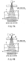
- a collimator 22 which trims X-rays into a pyramidal shape is attached to the X-ray radiation window of the X-ray tube 10.
- the opening degree of the collimator 22 is variable.
- the X-ray detector 11 opposes the X-ray tube 10 through an object P to be examined which is placed on a table top 2a of a bed 2.
- the X-ray detector 11 has a plurality of X-ray detection element lines 14, N X-ray detection element lines 14 in this case, arranged along the slice direction.
- Each X-ray detection element line 14 has a plurality of X-ray detection elements 13, M X-ray detection elements 13 in this case, arranged in the channel direction.
- the table top 2a of the bed 2 is moved along the slice direction by a bed driving unit 2b such as a servo motor under the control of a bed controller 32.
- a cabinet 3 includes a system controller 43 for controlling the operation of the overall system, a scan controller 30, a preprocessing unit 34, a data storing unit 35, a reconstructing unit 36, a display processor 37, a display 38, an input device (console) 39, a scanogram generating unit 43, a transmission factor calculating unit 41, and a tube current value calculating unit 42.
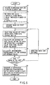
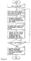
- FIG. 5 shows a transmission factor calculation procedure executed by the transmission factor calculating unit 41.
- scanogram data are acquired (S1).
- Scanogram data is essentially data that is acquired to be referred to when a scan plan including a scan range, imaging conditions, and the like is made. This scanogram data is also used as basic data for the calculation of a transmission factor.
- scanogram data is generally acquired by the center element line 14.
- the rotating frame 12 is fixed to, for example, an angle position of 0°, and the table top 2a is moved at a constant velocity. While the table top 2a is moved at a constant velocity, the X-ray tube 10 continuously emits X-rays having a low intensity.
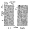
- the resolution in the slice direction of a scanogram is determined by the cycle at which signals are read out and the moving velocity of the table top 2a.
- the resolution in the channel direction of a scanogram is defined by a channel pitch. Assuming that one channel corresponds to one element, the channel pitch is equal to the element pitch, i.e., the distance between the center points of adjacent detection elements.
- the signals read at the predetermined cycle are sent to the scanogram generating unit 43 through a data acquisition system 24 and the preprocessing unit 34.
- the scanogram generating unit 43 associates channel number data and the position data in the slice direction of the table top 2a which is detected by a position sensor 25 with each channel data, thus generating scanogram data.
- the generated scanogram data is stored in the data storing unit 35.
- Each pixel value of this scanogram represents the intensity of transmitted X-rays.
- An X-ray transmission factor at each position in the slice direction can be calculated from the intensity of transmitted X-rays and a know generated X-ray intensity.
- a transmission factor at each position is calculated from the pixel values of a plurality of pixels included in a two-dimensional area centered on the position. This two-dimensional area is called a mask.
- the transmission factor calculating unit 41 sets a mask size (n x m) in accordance with a user instruction associated with the mask size input through the input device 39 (S2).
- the display processor 37 displays a scanogram on the display 38 in accordance with the scanogram data read out from the data storing unit 35, and superimposes a mask frame on this scanogram.
- FIG. 7A shows an example of the scanogram and default mask frame displayed on the display 38.
- the scan width is defined by the product of the number of slices and the slice thickness.
- the number of slices and the slice thickness are set by the user at the time of scan planning.
- the number of slices is set to at least two in a multi-slice scan.
- the slice thickness is defined by the thickness of one slice on the rotational center axis and selectively designated from a positive integer multiple of a reduced length on the rotational center axis of the sensible width of one X-ray detection element line 14.
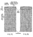
- the mask frame can be arbitrarily enlarged/reduced with the range of 2 ⁇ n ⁇ N and 2 ⁇ m ⁇ M in accordance with the operation of the input device 39 by the user. That is, a mask frame includes at least 2 ⁇ 2 pixels.
- the shape of the mask frame can be changed into an arbitrary polygonal shape including a cross shape in accordance with the operation of the input device 39 by the user.
- the shape of the mask frame can be changed into an elliptic or circular shape in accordance with the operation of the input device 39 by the user.
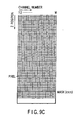
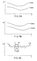
- the transmission factor calculating unit 41 places a mask at the start position with respect to the scanogram, as shown in FIG. 9A (S3).
- the pixel values of a plurality of pixels included in the mask at the position are selectively read out from the data storing unit 35 (S4).
- the average of the readout pixel values of the pixels is calculated (S5).
- the maximum value (or minimum value) of the readout pixel values of the pixels may be extracted instead of the average value.
- the user determines whether to calculate an average or extract a maximum or minimum value. If an average is selected, stable tube current control can be realized. If a maximum value is selected, tube current control effective for a reduction in dosage. If a minimum value is selected, tube current control effective for an increase in S/N can be realized.
- the average within this mask is equivalent to the value obtained by averaging the pixel values of a scanogram in the channel direction and calculating the moving average in the slice direction from the average in the channel direction.
- a tube current value is determined on the basis of scanogram data in a two-dimensional area.
- a tube current value may be determined on the basis of a distribution in a two-dimensional area associated with an output (called raw data) from the detector 11 before the creation of scanogram data.
- Raw data, scanogram data, and various types of index data obtained from the raw data are generically called X-ray data.
- the mask is moved in the slice direction by a unit distance (S8), and the processing in steps S4 to S6 is repeated until the mask reaches the end position in step S7 (see FIG. 9C ).
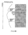
- the discrete distribution of X-ray transmission factors F(z) in the slice direction is generated.
- the above unit distance is initially set to either the resolution in the slice direction of the scanogram or the width of the detection element lines 14. The unit distance can be arbitrarily changed in accordance with an instruction from the user.
- a continuous distribution (to be referred to as a transmission profile) of X-ray transmission factors F(z) in the slice direction is generated from the discrete distribution of X-ray transmission factors F(z) in the slice direction by interpolation (S9).
- This transmission profile is stored in the data storing unit 35.
- the X-ray transmission factor F(z) at the shoulder or abdominal portion is lower than that at the chest portion. Since the lungs exist in the chest portion and the chest portion is mostly occupied by the air in the lungs, the X-ray transmission factor becomes high. In contrast to this, since the bones exist in the shoulder portion and the organs exist in the abdominal portion, the X-ray transmission factor becomes low.
- a transmission factor is calculated on the basis of the average (or maximum or minimum value) of transmitted X-ray intensities in a two-dimensional area spreading in not only the channel direction but also the slice direction. This makes it possible to realize suitable tube current control in a multi-slice scan with a significantly large field of view in the slice direction as compared with a single-slice scan.
- FIG. 11 shows a tube current control procedure using a transmission factor profile in a helical scan.
- a helical scan is started under the control of the scan controller 30 (S11).
- the table top 2a is moved at a constant velocity, and the X-ray tube 10 and X-ray detector 11 are continuously rotated together. During this period, X-ray are continuously generated, and signals are read from the X-ray detector 11 at a predetermined cycle.
- the position data of the table top 2a are sequentially supplied from the position sensor 25 to the scan controller 30 at a predetermined cycle (S12).
- the scan center position is the Z position of a central axis of X-rays diverging in the slice direction (Z-axis direction) in the moving coordinate system of the table top 2a.
- a transmission factor read request is output to the data storing unit 35, together with position data, under the control of the system controller 43.
- the X-ray transmission factor data corresponding to the position is read out from the data storing unit 35 to the tube current value calculating unit 42 (S13).
- the tube current value calculating unit 42 calculates a tube current value on the basis of the readout X-ray transmission factor (S14).
- FIG. 12A is a graph showing the general relationship between the X-ray transmission factor F(z) and the tube current (Itube). As shown in FIG. 12A , the X-ray transmission factor F(z) is proportional to the tube current value (Itube). By using such a graph, a tube current (Itube) value can be uniquely specified from the X-ray transmission factor F(z). In practice, a tube current value (Itube) is calculated from the readout X-ray transmission factor F(z) in accordance with a functional expression that defines the relationship between the X-ray transmission factor F(z) and the tube current (Itube).
- the relationship between the X-ray transmission factor F(z) and the tube current (Itube) may be calculated in advance, and the calculation result may be held in the form of a table.
- the tube current value calculating unit 42 is formed as a ROM designed to output a tube current value (Itube) corresponding to the input X-ray transmission factor F(z).
- the relationship between the X-ray transmission factor F(z) and the tube current (Itube) is not limited to the proportional relationship shown in FIG. 12A .
- the exponential function shown in FIG. 12A may be used.
- an upper limit (Itube, max) and lower limit (Itube, min) may be set for the tube current value (Itube). This makes it possible to always generate X-rays within the capacity range of the X-ray tube and prevent electrical discharge of the X-ray tube.
- the scan controller 30 controls a filament current such that a current flows between the cathode and the anode of the X-ray tube 10 in accordance with the determined tube current value (S15).
- the processing in steps S12 to S15 is repeated until the helical scan is terminated in step S16.
- the helical scan is terminated when the table top reaches the end position of the planned scan range (S17).
- the tube current Itube is dynamically changed upon movement of the table top 2a by controlling the tube current Itube on the basis of the profile of the transmission factor F(z) in the slice direction.
- the transmission factor F(z) is calculated on the basis of the average (or maximum or minimum value) of transmission X-ray intensities in the two-dimensional area spreading in not only the channel direction but also the slice direction, and a tube current is controlled on the basis of the transmission factor.
- a tube current is dynamically controlled in accordance with the movement of the table top 2a in the slice direction by using one transmission factor profile corresponding to one direction.
- a tube current may be controlled with higher precision in accordance with not only the movement of the table top 2a in the slice direction but also a change in the rotational angel of the X-ray tube 10.
- at least two transmission factor profiles corresponding to two directions are required.
- scanogram data are acquired while the X-ray tube 10 is fixed to an angle position of 0°.
- scanogram data are acquired while the X-ray tube 10 is fixed at an angle position of 90°.
- Scanogram data are acquired in two directions in this manner.
- Two transmission factor profiles Fx(z) and Fy(z) are generated on the basis of the two scanograms in different directions by the processing shown in FIG. 5 .
- the profile Fx(z) corresponds to the 0° position of the X-ray tube 10.
- the profile Fy(z) corresponds to the 90° position of the X-ray tube 10.
- FIG. 15A shows transmission factor profiles Fx(z)ave and Fy(z)ave obtained from the averages within the mask.
- 15B shows transmission factor profiles Fx(z)max and Fy(z)max obtained from the maximum values within the mask.
- the human body is flattened in the X direction, and hence Fy(z) is lower than Fx(z). The user can selectively use either of them.
- the X-ray transmission factor profile Fx(z) corresponds to the 0° rotation angle of the X-ray tube 10 (almost corresponds to 180° as well).
- the X-ray transmission factor profile Fy(z) corresponds to the 90° rotational angle of the X-ray tube 10 (almost corresponds to 270° as well).
- the transmission factor profile Fx(z) represents the maximum transmission factor throughout 360°. In contrast to this, the transmission factor profile Fy(z) represents the minimum transmission factor throughout 360°. Therefore, the actual transmission factor during a helical scan changes between the two transmission factor profiles Fx(z) and Fy(z) upon rotation of the X-ray tube 10.
- FIG. 15C shows a new transmission factor profile F'(z) generated such that a straight line or sine wave alternates twice between the transmission factor profiles Fx(z) and Fy(z) in each cycle.
- the tube current can be finely changed in accordance with not only a change in transmission factor due to the movement of the table top 2a but also a change in transmission factor due to the rotation of the X-ray tube 10.
- a transmission factor profile is obtained in advance on the basis of the scanogram data acquired before a scan, and a tube current is dynamically controlled during the scan in accordance with the transmission factor profile.
- a transmission factor may be calculated on the basis of the data acquired during a scan, and a tube current may be dynamically controlled along with the progress of a helical scan on the basis of the transmission factor.
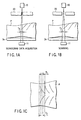
- basic data for the calculation of a transmission factor are acquired from detection element lines corresponding to a scan width T2, i.e., at least two detection element lines (oblique lines) preceding a detection element line that is set to acquire data for image reconstruction.
- a tube current at the position is determined in accordance with the transmission factor calculated from the basic data acquired at the reference position shown in FIG. 16A . That is, a transmission factor is calculated from the average (or maximum or minimum value) of transmitted X-ray intensities of a plurality of channels acquired by at least two preceding detection element lines.
- a tube current is controlled in accordance with the transmission factor.
- Basic data for the calculation of a transmission factor may be acquired by at least two detection element lines set to acquire data for image reconstruction before half rotation or one or a few rotations. That is, a transmission factor is calculated from the average (or maximum or minimum value) of transmitted X-ray intensities of a plurality of channels acquired by at least two detection element lines before one or a few rotations shown in FIG. 17A , and a tube current after one or a few rotations shown in FIG. 17B is dynamically controlled along with the progress of a helical scan in accordance with the transmission factor.
- the same effect as that described above can be obtained by controlling a tube current in real time on the basis of the data acquired by at least two element lines immediately before rotation.
Description
- The present invention relates to an X-ray computed tomography apparatus including an X-ray tube and multi-slice X-ray detectors.
- A significant challenge for recent X-ray computed tomographic imaging apparatuses is to realize both an improvement in image quality and a decrease in dosage. Image quality improves as the intensity of X-rays with which an object to be examined is irradiated decreases, and vice versa.
- In a conventional apparatus, the intensity of X-ray generated during a helical scan is maintained at a constant value. Recently, however, techniques of changing the intensity of X-rays in accordance with the X-ray transmission factor which changes in accordance with a region of the object have been proposed. In many of these proposals, the X-ray intensity is changed in accordance with a value at a given point on a scanogram. As is known, a scanogram is the two-dimensional intensity distribution of transmitted X-rays which is acquired for a scan plan.
- To acquire scanogram data, an
X-ray tube 10 is fixed at a given rotational angle, as shown inFIGS. 1A and2A . Atable top 2a is moved at a constant velocity. During this period, signals are repeatedly read from anX-ray detector 11 at a predetermined cycle. - This X-ray intensity control is effective in a single-slice scan shown in
FIG. 1B . As shown inFIG. 2B , however, X-ray intensity cannot be satisfactorily optimized for a multi-slice scan (also called a volume scan). The biggest reason for this is that in a multi-slice scan, data are acquired at once in a wide range with a slice width T2 larger than a slice width T1 in scanogram data acquisition. -
US 5,400,378 relates to a multi-slice X-ray CT system where the tube current is modulated. - It is an object of the present invention to further optimize X-ray intensity in a multi-slice scan.
- The present invention provides an apparatus according to
claim 1. - This summary of the invention does not necessarily describe all necessary features so that the invention may also be a sub-combination of these described features.
- The invention can be more fully understood from the following detailed description when taken in conjunction with the accompanying drawings, in which:
-
FIGS. 1A to 1C are views showing a conventional single-slice scan; -
FIGS. 2A to 2C are views showing a conventional multi-slice scan; -
FIG. 3 is a block diagram showing the arrangement of an X-ray computed tomography apparatus according to an embodiment of the present invention; -
FIG. 4 is a plan view of an X-ray detector inFIG. 3 ; -
FIG. 5 is a flow chart showing the flow of transmission factor calculation processing by a transmission factor calculating unit inFIG. 3 ; -
FIGS. 6A and 6B are views showing a data profile acquired by a center element line of an X-ray detector inFIG. 2 ; -
FIGS. 7A to 7D are views showing an example of the mask setting window in step S2 ofFIG. 5 ; -
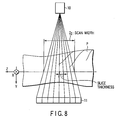
FIG. 8 is a view for a supplementary explanation of a scan width in step S2 ofFIG. 5 ; -
FIGS. 9A to 9C are views showing the start position, intermediate position, and end position of a mask in step S3 ofFIG. 5 ; -
FIGS. 10A and10B are views showing the discrete distribution of transmission factors calculated by the transmission factor calculating unit inFIG. 3 ; -
FIG. 11 is a flow chart showing the flow of tube current control (X-ray intensity control) in a helical scan by a scan controller inFIG. 3 ; -
FIGS. 12A to 12D are graphs showing various relationships between X-ray transmission factors and tube currents which are stored in a data storing unit inFIG. 3 ; -
FIG. 13 is a graph showing a change in tube current over time in this embodiment; -
FIG. 14 is a view showing how scanogram data in two orthogonal directions are acquired in a modification to this embodiment; -
FIGS. 15A to 15C are graphs showing a change in tube current over time in the modification to this embodiment; -
FIGS. 16A and 16B are views showing how basic data for a transmission factor are acquired during a scan in another modification to this embodiment; and -
FIGS. 17A and 17B are views showing how a scan is done in still another modification to this embodiment. - An X-ray computed tomographic imaging apparatus (X-ray CT apparatus) according to an embodiment of the present invention will be described below with reference to the views of the accompanying drawing. Note that X-ray CT apparatuses include various types of apparatuses, e.g., a rotate/rotate type apparatus in which an X-ray tube and X-ray detector rotate together around an object to be examined, and a stationary/rotate type apparatus in which many detection elements are arrayed in the form of a ring, and only an X-ray tube rotates around an object to be examined. The present invention can be applied to either type. In this case, the rotate/rotate type, which is currently the mainstream, will be exemplified.
- In order to reconstruct one-slice tomographic image data, 360° projection data corresponding to one rotation around an object to be examined is required, or (180° + view angle) projection data is required in the half scan method. The present invention can be applied to either of these reconstruction schemes. The half scan method will be exemplified here.
- As mechanisms of converting incident X-rays into electric charges, the following techniques are the mainstream: an indirect conversion type that converts X-rays into light through a phosphor such as a scintillator and converts the light into electric charges through photoelectric conversion elements such as photodiodes, and a direct conversion type that uses generation of electron-hole pairs in a semiconductor by X-rays and movement of the electron-hole pairs to an electrode, i.e., a photoconductive phenomenon. As an X-ray detection element, either of these schemes can be used. In this case, the former type, i.e., the indirect conversion type, will be exemplified.
- Recently, with advances toward the commercialization of a so-called multi-tube type X-ray CT apparatus having a plurality of pairs of X-ray tubes and X-ray detectors mounted on a rotating ring, related techniques have been developed. The present invention can be applied to both a conventional single-tube type X-ray CT apparatus and a multi-tube type X-ray CT apparatus. The single-tube type X-ray CT apparatus will be exemplified here.
-
FIG. 3 shows the arrangement of an X-ray computed tomographic imaging apparatus according to this embodiment. A substantially cylindrical rotatingframe 12 is housed in agantry 1. The rotatingframe 12 is rotated by agantry driving unit 25 under the control of a gantry controller 33 in scan operation, and fixed at a predetermined angle position, e.g., an angle position of 0° by the braking function of thegantry driving unit 25 at the time of scanogram data acquisition. AnX-ray tube 10 andX-ray detector 11 are mounted on the rotatingframe 12. Ahigh voltage generator 21 applies a high voltage (tube voltage) between the cathode and the anode of theX-ray tube 10 under the control of ahigh voltage controller 31. Thehigh voltage generator 21 supplies a filament current to the cathode filament under the control of thehigh voltage controller 31. A tube current that flows between the cathode and the anode is determined in accordance with the filament current. The intensity of X-rays generated is determined in accordance with the tube current. - A
collimator 22 which trims X-rays into a pyramidal shape is attached to the X-ray radiation window of theX-ray tube 10. The opening degree of thecollimator 22 is variable. TheX-ray detector 11 opposes theX-ray tube 10 through an object P to be examined which is placed on a table top 2a of abed 2. As shown inFIG. 4 , theX-ray detector 11 has a plurality of X-raydetection element lines 14, N X-raydetection element lines 14 in this case, arranged along the slice direction. Each X-raydetection element line 14 has a plurality ofX-ray detection elements 13, MX-ray detection elements 13 in this case, arranged in the channel direction. The table top 2a of thebed 2 is moved along the slice direction by abed driving unit 2b such as a servo motor under the control of abed controller 32. - A cabinet 3 includes a
system controller 43 for controlling the operation of the overall system, ascan controller 30, apreprocessing unit 34, adata storing unit 35, a reconstructingunit 36, adisplay processor 37, adisplay 38, an input device (console) 39, ascanogram generating unit 43, a transmissionfactor calculating unit 41, and a tube currentvalue calculating unit 42. -
FIG. 5 shows a transmission factor calculation procedure executed by the transmissionfactor calculating unit 41. First of all, scanogram data are acquired (S1). Scanogram data is essentially data that is acquired to be referred to when a scan plan including a scan range, imaging conditions, and the like is made. This scanogram data is also used as basic data for the calculation of a transmission factor. As shown inFIG. 6A , scanogram data is generally acquired by thecenter element line 14. In order to acquire scanogram data, the rotatingframe 12 is fixed to, for example, an angle position of 0°, and thetable top 2a is moved at a constant velocity. While thetable top 2a is moved at a constant velocity, theX-ray tube 10 continuously emits X-rays having a low intensity. While X-rays are continuously emitted, signals are read from thecenter element line 14 at a predetermined cycle (seeFIG. 6B ). The resolution in the slice direction of a scanogram is determined by the cycle at which signals are read out and the moving velocity of thetable top 2a. The resolution in the channel direction of a scanogram is defined by a channel pitch. Assuming that one channel corresponds to one element, the channel pitch is equal to the element pitch, i.e., the distance between the center points of adjacent detection elements. - The signals read at the predetermined cycle are sent to the
scanogram generating unit 43 through adata acquisition system 24 and thepreprocessing unit 34. Thescanogram generating unit 43 associates channel number data and the position data in the slice direction of thetable top 2a which is detected by aposition sensor 25 with each channel data, thus generating scanogram data. The generated scanogram data is stored in thedata storing unit 35. - Each pixel value of this scanogram represents the intensity of transmitted X-rays. An X-ray transmission factor at each position in the slice direction can be calculated from the intensity of transmitted X-rays and a know generated X-ray intensity. A transmission factor at each position is calculated from the pixel values of a plurality of pixels included in a two-dimensional area centered on the position. This two-dimensional area is called a mask.
- The transmission
factor calculating unit 41 sets a mask size (n x m) in accordance with a user instruction associated with the mask size input through the input device 39 (S2). To support inputting of a mask size, thedisplay processor 37 displays a scanogram on thedisplay 38 in accordance with the scanogram data read out from thedata storing unit 35, and superimposes a mask frame on this scanogram. -
FIG. 7A shows an example of the scanogram and default mask frame displayed on thedisplay 38. The default mask frame has a rectangular shape, and its matrix size is set to the number of pixels in the vertical direction which is determined by the scan width/the resolution in the slice direction (= N) and the number of pixels in the horizontal direction which is equal to the number of channels (= M) of each of the X-ray detection element lines 14. As shown inFIG. 8 , the scan width is defined by the product of the number of slices and the slice thickness. The number of slices and the slice thickness are set by the user at the time of scan planning. The number of slices is set to at least two in a multi-slice scan. The slice thickness is defined by the thickness of one slice on the rotational center axis and selectively designated from a positive integer multiple of a reduced length on the rotational center axis of the sensible width of one X-raydetection element line 14. - As shown in
FIG. 7B , the mask frame can be arbitrarily enlarged/reduced with the range of 2 < n < N and 2 < m < M in accordance with the operation of theinput device 39 by the user. That is, a mask frame includes at least 2 × 2 pixels. In addition, as shown inFIG. 7C , the shape of the mask frame can be changed into an arbitrary polygonal shape including a cross shape in accordance with the operation of theinput device 39 by the user. In addition, as shown inFIG. 7D , the shape of the mask frame can be changed into an elliptic or circular shape in accordance with the operation of theinput device 39 by the user. - After a mask size is determined, the transmission
factor calculating unit 41 places a mask at the start position with respect to the scanogram, as shown inFIG. 9A (S3). The pixel values of a plurality of pixels included in the mask at the position are selectively read out from the data storing unit 35 (S4). The average of the readout pixel values of the pixels is calculated (S5). The maximum value (or minimum value) of the readout pixel values of the pixels may be extracted instead of the average value. The user determines whether to calculate an average or extract a maximum or minimum value. If an average is selected, stable tube current control can be realized. If a maximum value is selected, tube current control effective for a reduction in dosage. If a minimum value is selected, tube current control effective for an increase in S/N can be realized. - Note that the average within this mask is equivalent to the value obtained by averaging the pixel values of a scanogram in the channel direction and calculating the moving average in the slice direction from the average in the channel direction.
- The transmission
factor calculating unit 41 then calculates a transmission factor F8(z) corresponding to a center position z in the slice direction of the mask on the basis of the average (or maximum or minimum value) in the two-dimensional area according to the following equation:
- According to the above description, a tube current value is determined on the basis of scanogram data in a two-dimensional area. However, a tube current value may be determined on the basis of a distribution in a two-dimensional area associated with an output (called raw data) from the
detector 11 before the creation of scanogram data. Raw data, scanogram data, and various types of index data obtained from the raw data are generically called X-ray data. - As shown in
FIG. 9B , the mask is moved in the slice direction by a unit distance (S8), and the processing in steps S4 to S6 is repeated until the mask reaches the end position in step S7 (seeFIG. 9C ). With this operation, as shown inFIGS. 10A and10B , the discrete distribution of X-ray transmission factors F(z) in the slice direction is generated. Note that the above unit distance is initially set to either the resolution in the slice direction of the scanogram or the width of the detection element lines 14. The unit distance can be arbitrarily changed in accordance with an instruction from the user. - A continuous distribution (to be referred to as a transmission profile) of X-ray transmission factors F(z) in the slice direction is generated from the discrete distribution of X-ray transmission factors F(z) in the slice direction by interpolation (S9). This transmission profile is stored in the
data storing unit 35. - In general, the X-ray transmission factor F(z) at the shoulder or abdominal portion is lower than that at the chest portion. Since the lungs exist in the chest portion and the chest portion is mostly occupied by the air in the lungs, the X-ray transmission factor becomes high. In contrast to this, since the bones exist in the shoulder portion and the organs exist in the abdominal portion, the X-ray transmission factor becomes low.
- Note that in this embodiment, a transmission factor is calculated on the basis of the average (or maximum or minimum value) of transmitted X-ray intensities in a two-dimensional area spreading in not only the channel direction but also the slice direction. This makes it possible to realize suitable tube current control in a multi-slice scan with a significantly large field of view in the slice direction as compared with a single-slice scan.
-
FIG. 11 shows a tube current control procedure using a transmission factor profile in a helical scan. A helical scan is started under the control of the scan controller 30 (S11). In the helical scan, thetable top 2a is moved at a constant velocity, and theX-ray tube 10 andX-ray detector 11 are continuously rotated together. During this period, X-ray are continuously generated, and signals are read from theX-ray detector 11 at a predetermined cycle. - The position data of the
table top 2a are sequentially supplied from theposition sensor 25 to thescan controller 30 at a predetermined cycle (S12). For the sake of descriptive convenience, assume that the position of thetable top 2a coincides with a scan center position. The scan center position is the Z position of a central axis of X-rays diverging in the slice direction (Z-axis direction) in the moving coordinate system of thetable top 2a. A transmission factor read request is output to thedata storing unit 35, together with position data, under the control of thesystem controller 43. The X-ray transmission factor data corresponding to the position is read out from thedata storing unit 35 to the tube current value calculating unit 42 (S13). The tube currentvalue calculating unit 42 calculates a tube current value on the basis of the readout X-ray transmission factor (S14). -
FIG. 12A is a graph showing the general relationship between the X-ray transmission factor F(z) and the tube current (Itube). As shown inFIG. 12A , the X-ray transmission factor F(z) is proportional to the tube current value (Itube). By using such a graph, a tube current (Itube) value can be uniquely specified from the X-ray transmission factor F(z). In practice, a tube current value (Itube) is calculated from the readout X-ray transmission factor F(z) in accordance with a functional expression that defines the relationship between the X-ray transmission factor F(z) and the tube current (Itube). Alternatively, the relationship between the X-ray transmission factor F(z) and the tube current (Itube) may be calculated in advance, and the calculation result may be held in the form of a table. In this case, the tube currentvalue calculating unit 42 is formed as a ROM designed to output a tube current value (Itube) corresponding to the input X-ray transmission factor F(z). - The relationship between the X-ray transmission factor F(z) and the tube current (Itube) is not limited to the proportional relationship shown in
FIG. 12A . The exponential function shown inFIG. 12A may be used. In practice, X-rays are exponentially attenuated when passing through the object P, and hence using an exponential curve (Itube = expFx(z)) as the relationship between the X-ray transmission factor F(z) and the tube current (Itube) is a more practical. This therefore makes it possible to obtain a more suitable tube current value (Itube). As shown inFIGS. 12C and 12D , an upper limit (Itube, max) and lower limit (Itube, min) may be set for the tube current value (Itube). This makes it possible to always generate X-rays within the capacity range of the X-ray tube and prevent electrical discharge of the X-ray tube. - Referring back to
FIG. 11 , thescan controller 30 controls a filament current such that a current flows between the cathode and the anode of theX-ray tube 10 in accordance with the determined tube current value (S15). The processing in steps S12 to S15 is repeated until the helical scan is terminated in step S16. The helical scan is terminated when the table top reaches the end position of the planned scan range (S17). - As shown in
FIG. 13 , the tube current Itube is dynamically changed upon movement of thetable top 2a by controlling the tube current Itube on the basis of the profile of the transmission factor F(z) in the slice direction. The transmission factor F(z) is calculated on the basis of the average (or maximum or minimum value) of transmission X-ray intensities in the two-dimensional area spreading in not only the channel direction but also the slice direction, and a tube current is controlled on the basis of the transmission factor. With this operation, suitable tube current control can be realized even in a multi-slice scan with a wide field of view in the slice direction as compared with a single-slice scan. - The difference between the effect obtained by using the average of transmitted X-ray intensities in a two-dimensional area to control a tube current (Itube) and that obtained by using the maximum value (minimum value) will be briefly described below. When the average is used, an abrupt change in the X-ray transmission factor of an object can be properly handled, and the occurrence of extremely ugly image noise, artifacts, and the like can be prevented, thus always suppressing the image noise, artifacts, and the like uniformly (with a certain range). If the maximum value (or minimum value) is used, image noise, artifacts, and the like can be suppressed more.
- According to the above description, a tube current is dynamically controlled in accordance with the movement of the table top 2a in the slice direction by using one transmission factor profile corresponding to one direction. A tube current may be controlled with higher precision in accordance with not only the movement of the table top 2a in the slice direction but also a change in the rotational angel of the
X-ray tube 10. For this purpose, at least two transmission factor profiles corresponding to two directions are required. - As shown in
FIG. 14 , scanogram data are acquired while theX-ray tube 10 is fixed to an angle position of 0°. In addition, scanogram data are acquired while theX-ray tube 10 is fixed at an angle position of 90°. Scanogram data are acquired in two directions in this manner. Two transmission factor profiles Fx(z) and Fy(z) are generated on the basis of the two scanograms in different directions by the processing shown inFIG. 5 . The profile Fx(z) corresponds to the 0° position of theX-ray tube 10. The profile Fy(z) corresponds to the 90° position of theX-ray tube 10.FIG. 15A shows transmission factor profiles Fx(z)ave and Fy(z)ave obtained from the averages within the mask.FIG. 15B shows transmission factor profiles Fx(z)max and Fy(z)max obtained from the maximum values within the mask. In general, the human body is flattened in the X direction, and hence Fy(z) is lower than Fx(z). The user can selectively use either of them. - The X-ray transmission factor profile Fx(z) corresponds to the 0° rotation angle of the X-ray tube 10 (almost corresponds to 180° as well). The X-ray transmission factor profile Fy(z) corresponds to the 90° rotational angle of the X-ray tube 10 (almost corresponds to 270° as well). The transmission factor profile Fx(z) represents the maximum transmission factor throughout 360°. In contrast to this, the transmission factor profile Fy(z) represents the minimum transmission factor throughout 360°. Therefore, the actual transmission factor during a helical scan changes between the two transmission factor profiles Fx(z) and Fy(z) upon rotation of the
X-ray tube 10. The distance (helical pitch) the table top moves while theX-ray tube 10 makes one rotation is defined as one cycle.FIG. 15C shows a new transmission factor profile F'(z) generated such that a straight line or sine wave alternates twice between the transmission factor profiles Fx(z) and Fy(z) in each cycle. - By controlling a tube current in accordance with this transmission factor profile F'(z), the tube current can be finely changed in accordance with not only a change in transmission factor due to the movement of the
table top 2a but also a change in transmission factor due to the rotation of theX-ray tube 10. - According to the above description, a transmission factor profile is obtained in advance on the basis of the scanogram data acquired before a scan, and a tube current is dynamically controlled during the scan in accordance with the transmission factor profile. However, a transmission factor may be calculated on the basis of the data acquired during a scan, and a tube current may be dynamically controlled along with the progress of a helical scan on the basis of the transmission factor.
- As shown in
FIGS. 16A and 16B , basic data for the calculation of a transmission factor are acquired from detection element lines corresponding to a scan width T2, i.e., at least two detection element lines (oblique lines) preceding a detection element line that is set to acquire data for image reconstruction. For example, when basic data are acquired at the reference position shown inFIG. 16A and a helical scan proceeds the position shown inFIG. 16B , a tube current at the position is determined in accordance with the transmission factor calculated from the basic data acquired at the reference position shown inFIG. 16A . That is, a transmission factor is calculated from the average (or maximum or minimum value) of transmitted X-ray intensities of a plurality of channels acquired by at least two preceding detection element lines. When the center of a detection element line set to acquire data for image reconstruction reaches the position where the transmission factor data are acquired, a tube current is controlled in accordance with the transmission factor. - Basic data for the calculation of a transmission factor may be acquired by at least two detection element lines set to acquire data for image reconstruction before half rotation or one or a few rotations. That is, a transmission factor is calculated from the average (or maximum or minimum value) of transmitted X-ray intensities of a plurality of channels acquired by at least two detection element lines before one or a few rotations shown in
FIG. 17A , and a tube current after one or a few rotations shown inFIG. 17B is dynamically controlled along with the progress of a helical scan in accordance with the transmission factor. - As described above, the same effect as that described above can be obtained by controlling a tube current in real time on the basis of the data acquired by at least two element lines immediately before rotation.
Claims (12)
- An X-ray computed tomography apparatus comprising:an X-ray tube (10) configured to generate X-rays with which an object to be examined is irradiated;a high voltage generator (21) configured to generate a high voltage to be applied to said X-ray tube;an X-ray detector (23) configured to have a plurality of X-ray detection element lines (14) for detecting X-rays transmitted through the object;a scanogram generating unit (43) configured to generate a scanogram on the basis of an output from said X-ray detector;a reconstructing unit (36) configured to reconstruct an image on the basis of the output from said X-ray detector;a tube current determining unit (41, 42) configured to determine tube current values corresponding to slice positions for said X-ray tube, anda control unit (30) configured to control a tube current value of said X-ray tube on the basis of the determined tube current value,
characterized by each of the tube current values being determined on the basis of pixel values of a plurality of pixels included in respective two-dimensional partial regions including the corresponded slice position of the scanogram, the two-dimensional partial region spreading in both a slice direction and a channel direction such that it spreads over at least two pixels in the channel direction and two pixels in the slice direction. - An apparatus according to claim 1, characterized in that the two-dimensional partial region has a size corresponding to the number of detection element lines corresponding to an aperture width of a collimator in the slice direction, which is placed between said X-ray tube and the object, and the number of channels constituting each of the detection element lines.
- An apparatus according to claim 1, characterized by said tube current determining unit configured to determine a tube current value for said X-ray tube on the basis of an average of pixel values of a plurality of pixels included in the two-dimensional partial region.
- An apparatus according to claim 3, characterized by further comprising a storing unit (35) which stores a table in which the tube current value is associated with the average.
- An apparatus according to claim 1, characterized by said tube current determining unit configured to determine a tube current value for said X-ray tube on the basis of a maximum or minimum value of pixel values of a plurality of pixels included in the two-dimensional partial region.
- An apparatus according to claim 1, characterized by said tube current determining unit configured to determine a plurality of tube current values at a plurality of discrete positions, and said control unit configured to dynamically change a tube current of said X-ray tube on the basis of the determined plurality of tube current values upon movement of the object.
- An apparatus according to claim 6, characterized by said tube current determining unit configured to interpolate a tube current value corresponding to an intermediate position of the plurality of discrete positions from the determined tube current value.
- An apparatus according to any preceding claim, characterized by said reconstructing unit configured to reconstruct the image on the basis of outputs from at least two x-ray detection element lines selected from said plurality of X-ray detection element lines in accordance with a user instruction.
- An apparatus according to claim 8, characterized in that the two-dimensional partial region has a size corresponding to the number of channels constituting each of said X-ray detection element lines and the number of selected X-ray detection element lines.
- An apparatus according to any preceding claim, characterized by further comprising a display unit (37, 38) configured to display the a size of scanogram together with a frame representing the two-dimensional partial region.
- An apparatus according to claim 10, characterized by further comprising an input device (39) being used to arbitrarily change a size of the frame.
- An apparatus according to claim 10, characterized by further comprising an input device (39) being used to arbitrarily change a shape of the frame.
Applications Claiming Priority (4)
| Application Number | Priority Date | Filing Date | Title |
|---|---|---|---|
| JP2001324024 | 2001-10-22 | ||
| JP2001324024 | 2001-10-22 | ||
| JP2002276917A JP4309631B2 (en) | 2001-10-22 | 2002-09-24 | X-ray computer tomography equipment |
| JP2002276917 | 2002-09-24 |
Publications (3)
| Publication Number | Publication Date |
|---|---|
| EP1304077A2 EP1304077A2 (en) | 2003-04-23 |
| EP1304077A3 EP1304077A3 (en) | 2003-12-03 |
| EP1304077B1 true EP1304077B1 (en) | 2009-12-30 |
Family
ID=26624023
Family Applications (1)
| Application Number | Title | Priority Date | Filing Date |
|---|---|---|---|
| EP02256988A Expired - Lifetime EP1304077B1 (en) | 2001-10-22 | 2002-10-04 | X-ray computed tomography apparatus |
Country Status (5)
| Country | Link |
|---|---|
| US (2) | US20030076919A1 (en) |
| EP (1) | EP1304077B1 (en) |
| JP (1) | JP4309631B2 (en) |
| CN (1) | CN1230123C (en) |
| DE (1) | DE60234895D1 (en) |
Families Citing this family (36)
| Publication number | Priority date | Publication date | Assignee | Title |
|---|---|---|---|---|
| US7103134B2 (en) * | 2001-12-28 | 2006-09-05 | Kabushiki Kaisha Toshiba | Computed tomography apparatus |
| JP4537037B2 (en) * | 2003-11-11 | 2010-09-01 | 東芝Itコントロールシステム株式会社 | X-ray inspection apparatus and tube voltage / tube current adjustment method thereof |
| DE102004003532A1 (en) | 2004-01-23 | 2005-08-18 | Siemens Ag | Three-dimensional structure determination method for use in determining the position of a structure in a patient, whereby at least two X-ray tube-detector combinations at fixed angles to each other are used simultaneously |
| JP4679068B2 (en) * | 2004-04-26 | 2011-04-27 | 株式会社東芝 | X-ray computed tomography system |
| CN100393281C (en) * | 2004-07-23 | 2008-06-11 | 株式会社东芝 | X-ray computed tomography apparatus |
| US7636416B2 (en) * | 2005-02-25 | 2009-12-22 | Hitachi Medical Corporation | X-ray CT apparatus comprising a tube current control unit |
| JP4718949B2 (en) * | 2005-09-22 | 2011-07-06 | 株式会社東芝 | X-ray CT apparatus and X-ray CT apparatus manufacturing method |
| DE102005061559A1 (en) * | 2005-12-22 | 2007-07-05 | Siemens Ag | Method of operating an x-ray computer tomography apparatus for generating angiograph images having selectable first and second operating modes |
| JP2008220653A (en) | 2007-03-13 | 2008-09-25 | Toshiba Corp | X-ray ct apparatus, method for estimating outline of subject and method for reconstituting image |
| US20100213809A1 (en) * | 2007-09-19 | 2010-08-26 | Osram Gesellschaft Mit Beschraenkter Haftung | Headlamp and its use |
| CN101467888B (en) * | 2007-12-28 | 2013-03-27 | Ge医疗系统环球技术有限公司 | X ray CT device and X ray tube current determining method |
| DE102008014738A1 (en) * | 2008-03-18 | 2009-09-24 | Siemens Aktiengesellschaft | Medical imaging method and medical imaging device |
| JP5523726B2 (en) * | 2008-04-04 | 2014-06-18 | 株式会社東芝 | X-ray CT system |
| WO2010001845A1 (en) * | 2008-07-04 | 2010-01-07 | 株式会社 日立メディコ | X-ray ct device |
| US8300765B2 (en) * | 2008-08-04 | 2012-10-30 | Koninklijke Philips Electronics N.V. | Interventional imaging and data processing |
| JP2010213798A (en) * | 2009-03-13 | 2010-09-30 | Toshiba Corp | Cardiovascular x-ray diagnostic system |
| JP5642439B2 (en) * | 2010-07-06 | 2014-12-17 | ジーイー・メディカル・システムズ・グローバル・テクノロジー・カンパニー・エルエルシー | Radiation tomography system |
| US8971493B2 (en) | 2010-09-08 | 2015-03-03 | Siemens Medical Solutions Usa, Inc. | System for image scanning and acquisition with low-dose radiation |
| JP5718014B2 (en) * | 2010-10-22 | 2015-05-13 | 株式会社日立メディコ | X-ray CT system |
| JP5985836B2 (en) * | 2011-03-03 | 2016-09-06 | ゼネラル・エレクトリック・カンパニイ | Method for reducing the amount of radiation emitted by an imaging system |
| US9326738B2 (en) * | 2011-06-30 | 2016-05-03 | General Electric Company | Method and system for reduced dose X-ray imaging |
| JP6129474B2 (en) * | 2012-02-09 | 2017-05-17 | 東芝メディカルシステムズ株式会社 | X-ray diagnostic equipment |
| JP6108695B2 (en) * | 2012-06-15 | 2017-04-05 | キヤノン株式会社 | X-ray imaging control apparatus and method |
| CN104812305B (en) * | 2012-12-27 | 2018-03-30 | 东芝医疗系统株式会社 | X ray CT device and control method |
| US9370330B2 (en) | 2013-02-08 | 2016-06-21 | Siemens Medical Solutions Usa, Inc. | Radiation field and dose control |
| KR101534098B1 (en) * | 2013-09-13 | 2015-07-07 | 삼성전자주식회사 | Computed tomography apparatus and method for controlling x-ray by using the same |
| JP5784090B2 (en) * | 2013-09-30 | 2015-09-24 | 株式会社東芝 | X-ray CT system |
| KR102156408B1 (en) * | 2013-11-19 | 2020-09-16 | 삼성전자주식회사 | Display device and image generating method for layered display scheme |
| CN104302081B (en) * | 2014-09-24 | 2017-06-16 | 沈阳东软医疗系统有限公司 | The control method and equipment of heater current in a kind of CT bulbs |
| CN104287768A (en) * | 2014-09-30 | 2015-01-21 | 沈阳东软医疗系统有限公司 | Method and system for controlling CT scan dose |
| CN104819988A (en) * | 2015-05-07 | 2015-08-05 | 哈尔滨飞机工业集团有限责任公司 | Method of determining moulded gasbag of tail rotor blade through CT detection |
| US10085698B2 (en) * | 2016-01-26 | 2018-10-02 | Genereal Electric Company | Methods and systems for automated tube current modulation |
| CN106725570B (en) * | 2016-12-30 | 2019-12-20 | 上海联影医疗科技有限公司 | Imaging method and system |
| US10973489B2 (en) * | 2017-09-29 | 2021-04-13 | General Electric Company | CT imaging system and method using a task-based image quality metric to achieve a desired image quality |
| KR102286358B1 (en) * | 2018-08-10 | 2021-08-05 | 도시바 아이티 앤 콘트롤 시스템 가부시키가이샤 | X-ray imaging apparatus |
| CN109200490A (en) * | 2018-11-02 | 2019-01-15 | 新瑞阳光粒子医疗装备(无锡)有限公司 | CT machine, CT system, CT system control method and medium |
Citations (5)
| Publication number | Priority date | Publication date | Assignee | Title |
|---|---|---|---|---|
| US5379333A (en) * | 1993-11-19 | 1995-01-03 | General Electric Company | Variable dose application by modulation of x-ray tube current during CT scanning |
| US5400368A (en) * | 1993-08-17 | 1995-03-21 | Teknekron Communications Systems, Inc. | Method and apparatus for adjusting the sampling phase of a digitally encoded signal in a wireless communication system |
| US5450462A (en) * | 1993-11-19 | 1995-09-12 | General Electric Company | Modulation of x-ray tube current during CT scanning with modulation limit |
| US5485494A (en) * | 1994-08-03 | 1996-01-16 | General Electric Company | Modulation of X-ray tube current during CT scanning |
| WO1998033361A1 (en) * | 1997-01-29 | 1998-07-30 | Picker Medical Systems, Ltd. | Variable current ct scanning |
Family Cites Families (17)
| Publication number | Priority date | Publication date | Assignee | Title |
|---|---|---|---|---|
| JP2605048B2 (en) | 1987-07-02 | 1997-04-30 | 株式会社日立製作所 | Identification signal recording / reproducing device |
| JPH0636793B2 (en) * | 1988-05-20 | 1994-05-18 | 株式会社東芝 | X-ray CT scan |
| US5400378A (en) * | 1993-11-19 | 1995-03-21 | General Electric Company | Dynamic dose control in multi-slice CT scan |
| US5625662A (en) * | 1995-11-20 | 1997-04-29 | General Electric Company | Modulating x-ray tube current in a CT system |
| US5696807A (en) * | 1996-09-05 | 1997-12-09 | General Electric Company | Methods and apparatus for modulating x-ray tube current |
| US5867555A (en) * | 1997-03-04 | 1999-02-02 | Siemens Aktiengesellschaft | Adaptive dose modulation during CT scanning |
| US5822393A (en) * | 1997-04-01 | 1998-10-13 | Siemens Aktiengesellschaft | Method for adaptively modulating the power level of an x-ray tube of a computer tomography (CT) system |
| DE19721535C2 (en) * | 1997-05-22 | 2001-09-06 | Siemens Ag | X-ray computer tomograph for generating X-ray silhouettes |
| EP0942682B1 (en) * | 1997-06-26 | 2008-12-03 | Koninklijke Philips Electronics N.V. | Adjustable computer tomography device |
| JP3244458B2 (en) * | 1997-09-30 | 2002-01-07 | ジーイー横河メディカルシステム株式会社 | X-ray tomography equipment |
| US5982846A (en) * | 1998-04-13 | 1999-11-09 | General Electric Company | Methods and apparatus for dose reduction in a computed tomograph |
| US6385280B1 (en) * | 1998-08-18 | 2002-05-07 | Siemens Aktiengesellschaft | X-ray computed tomography apparatus with modulation of the x-ray power of the x-ray source |
| US6061420A (en) * | 1998-08-25 | 2000-05-09 | General Electric Company | Methods and apparatus for graphical Rx in a multislice imaging system |
| JP4260966B2 (en) | 1999-03-12 | 2009-04-30 | 株式会社東芝 | X-ray computed tomography system |
| JP4519254B2 (en) * | 2000-04-03 | 2010-08-04 | 株式会社日立メディコ | X-ray CT system |
| JP3961249B2 (en) * | 2001-08-28 | 2007-08-22 | ジーイー・メディカル・システムズ・グローバル・テクノロジー・カンパニー・エルエルシー | X-ray CT system, gantry apparatus, operation console and control method thereof, program code, and storage medium |
| US6795526B2 (en) * | 2002-03-04 | 2004-09-21 | Ge Medical Systems Global Technology Co., Llc | Automatic exposure control for a digital image acquisition system |
-
2002
- 2002-09-24 JP JP2002276917A patent/JP4309631B2/en not_active Expired - Fee Related
- 2002-10-03 US US10/262,895 patent/US20030076919A1/en not_active Abandoned
- 2002-10-04 EP EP02256988A patent/EP1304077B1/en not_active Expired - Lifetime
- 2002-10-04 DE DE60234895T patent/DE60234895D1/en not_active Expired - Lifetime
- 2002-10-22 CN CNB021471185A patent/CN1230123C/en not_active Expired - Lifetime
-
2005
- 2005-04-18 US US11/107,901 patent/US7142630B2/en not_active Expired - Lifetime
Patent Citations (5)
| Publication number | Priority date | Publication date | Assignee | Title |
|---|---|---|---|---|
| US5400368A (en) * | 1993-08-17 | 1995-03-21 | Teknekron Communications Systems, Inc. | Method and apparatus for adjusting the sampling phase of a digitally encoded signal in a wireless communication system |
| US5379333A (en) * | 1993-11-19 | 1995-01-03 | General Electric Company | Variable dose application by modulation of x-ray tube current during CT scanning |
| US5450462A (en) * | 1993-11-19 | 1995-09-12 | General Electric Company | Modulation of x-ray tube current during CT scanning with modulation limit |
| US5485494A (en) * | 1994-08-03 | 1996-01-16 | General Electric Company | Modulation of X-ray tube current during CT scanning |
| WO1998033361A1 (en) * | 1997-01-29 | 1998-07-30 | Picker Medical Systems, Ltd. | Variable current ct scanning |
Also Published As
| Publication number | Publication date |
|---|---|
| DE60234895D1 (en) | 2010-02-11 |
| US7142630B2 (en) | 2006-11-28 |
| US20030076919A1 (en) | 2003-04-24 |
| CN1413558A (en) | 2003-04-30 |
| EP1304077A3 (en) | 2003-12-03 |
| JP2003199739A (en) | 2003-07-15 |
| JP4309631B2 (en) | 2009-08-05 |
| CN1230123C (en) | 2005-12-07 |
| EP1304077A2 (en) | 2003-04-23 |
| US20050185760A1 (en) | 2005-08-25 |
Similar Documents
| Publication | Publication Date | Title |
|---|---|---|
| EP1304077B1 (en) | X-ray computed tomography apparatus | |
| EP1762176B1 (en) | X-ray computed tomography apparatus | |
| US7215733B2 (en) | X-ray computed tomography apparatus | |
| JP4187289B2 (en) | Method and system for modulating x-ray tube current and system for dynamically adjusting at least one component of a computed tomography imaging system | |
| JP4490645B2 (en) | X-ray computed tomography system | |
| JP2004180715A (en) | X-ray computed tomography apparatus | |
| US20040101105A1 (en) | X-ray controlling method and X-ray imaging apparatus | |
| JP2004329661A (en) | X-ray computerized tomographic apparatus and image noise simulation apparatus | |
| JP4159188B2 (en) | Tube current adjusting method and apparatus, and X-ray CT apparatus | |
| WO2014123041A1 (en) | X-ray ct device and image reconstruction method | |
| JP2004337289A (en) | Radiographic apparatus and its controlling method | |
| JP5022690B2 (en) | Radiography equipment | |
| US6917665B2 (en) | X-ray computed tomography apparatus | |
| JP2008221016A (en) | X-ray computer tomography apparatus | |
| EP1077045B1 (en) | Projection data correction method and apparatus, and radiation tomographic imaging method and apparatus | |
| JP4679951B2 (en) | X-ray CT system | |
| JP3950612B2 (en) | X-ray CT system | |
| JP6373558B2 (en) | X-ray CT system | |
| JP6490912B2 (en) | X-ray CT system | |
| JP4648355B2 (en) | Tube current adjusting method and apparatus, and X-ray CT apparatus | |
| JP5203750B2 (en) | ECG synchronous scanning method and X-ray computed tomography apparatus | |
| JP4607364B2 (en) | X-ray CT system |
Legal Events
| Date | Code | Title | Description |
|---|---|---|---|
| PUAI | Public reference made under article 153(3) epc to a published international application that has entered the european phase |
Free format text: ORIGINAL CODE: 0009012 |
|
| 17P | Request for examination filed |
Effective date: 20021016 |
|
| AK | Designated contracting states |
Designated state(s): AT BE BG CH CY CZ DE DK EE ES FI FR GB GR IE IT LI LU MC NL PT SE SK TR |
|
| AX | Request for extension of the european patent |
Extension state: AL LT LV MK RO SI |
|
| PUAL | Search report despatched |
Free format text: ORIGINAL CODE: 0009013 |
|
| AK | Designated contracting states |
Kind code of ref document: A3 Designated state(s): AT BE BG CH CY CZ DE DK EE ES FI FR GB GR IE IT LI LU MC NL PT SE SK TR |
|
| AX | Request for extension of the european patent |
Extension state: AL LT LV MK RO SI |
|
| AKX | Designation fees paid |
Designated state(s): DE FR GB NL |
|
| 17Q | First examination report despatched |
Effective date: 20050201 |
|
| 17Q | First examination report despatched |
Effective date: 20050201 |
|
| GRAP | Despatch of communication of intention to grant a patent |
Free format text: ORIGINAL CODE: EPIDOSNIGR1 |
|
| GRAS | Grant fee paid |
Free format text: ORIGINAL CODE: EPIDOSNIGR3 |
|
| GRAA | (expected) grant |
Free format text: ORIGINAL CODE: 0009210 |
|
| AK | Designated contracting states |
Kind code of ref document: B1 Designated state(s): DE FR GB NL |
|
| REG | Reference to a national code |
Ref country code: GB Ref legal event code: FG4D |
|
| REF | Corresponds to: |
Ref document number: 60234895 Country of ref document: DE Date of ref document: 20100211 Kind code of ref document: P |
|
| REG | Reference to a national code |
Ref country code: NL Ref legal event code: T3 |
|
| PLBE | No opposition filed within time limit |
Free format text: ORIGINAL CODE: 0009261 |
|
| STAA | Information on the status of an ep patent application or granted ep patent |
Free format text: STATUS: NO OPPOSITION FILED WITHIN TIME LIMIT |
|
| 26N | No opposition filed |
Effective date: 20101001 |
|
| REG | Reference to a national code |
Ref country code: FR Ref legal event code: PLFP Year of fee payment: 14 |
|
| REG | Reference to a national code |
Ref country code: FR Ref legal event code: PLFP Year of fee payment: 15 |
|
| REG | Reference to a national code |
Ref country code: GB Ref legal event code: 732E Free format text: REGISTERED BETWEEN 20160825 AND 20160831 Ref country code: NL Ref legal event code: PD Owner name: TOSHIBA MEDICAL SYSTEMS CORPORATION; JP Free format text: DETAILS ASSIGNMENT: VERANDERING VAN EIGENAAR(S), OVERDRACHT; FORMER OWNER NAME: KABUSHIKI KAISHA TOSHIBA Effective date: 20160627 |
|
| REG | Reference to a national code |
Ref country code: FR Ref legal event code: TP Owner name: TOSHIBA MEDICAL SYSTEMS CORPORATION, JP Effective date: 20160830 |
|
| REG | Reference to a national code |
Ref country code: DE Ref legal event code: R081 Ref document number: 60234895 Country of ref document: DE Owner name: TOSHIBA MEDICAL SYSTEMS CORPORATION, OTAWARA-S, JP Free format text: FORMER OWNER: KABUSHIKI KAISHA TOSHIBA, TOKIO/TOKYO, JP Ref country code: DE Ref legal event code: R082 Ref document number: 60234895 Country of ref document: DE Representative=s name: KRAMER BARSKE SCHMIDTCHEN PATENTANWAELTE PARTG, DE |
|
| REG | Reference to a national code |
Ref country code: FR Ref legal event code: PLFP Year of fee payment: 16 |
|
| REG | Reference to a national code |
Ref country code: FR Ref legal event code: PLFP Year of fee payment: 17 |
|
| PGFP | Annual fee paid to national office [announced via postgrant information from national office to epo] |
Ref country code: NL Payment date: 20210915 Year of fee payment: 20 Ref country code: FR Payment date: 20210826 Year of fee payment: 20 |
|
| PGFP | Annual fee paid to national office [announced via postgrant information from national office to epo] |
Ref country code: GB Payment date: 20210825 Year of fee payment: 20 |
|
| PGFP | Annual fee paid to national office [announced via postgrant information from national office to epo] |
Ref country code: DE Payment date: 20210824 Year of fee payment: 20 |
|
| REG | Reference to a national code |
Ref country code: DE Ref legal event code: R071 Ref document number: 60234895 Country of ref document: DE |
|
| REG | Reference to a national code |
Ref country code: NL Ref legal event code: MK Effective date: 20221003 |
|
| REG | Reference to a national code |
Ref country code: GB Ref legal event code: PE20 Expiry date: 20221003 |
|
| PG25 | Lapsed in a contracting state [announced via postgrant information from national office to epo] |
Ref country code: GB Free format text: LAPSE BECAUSE OF EXPIRATION OF PROTECTION Effective date: 20221003 |