JP6571313B2 - Medical image diagnostic apparatus and control method - Google Patents
Medical image diagnostic apparatus and control method Download PDFInfo
- Publication number
- JP6571313B2 JP6571313B2 JP2014110585A JP2014110585A JP6571313B2 JP 6571313 B2 JP6571313 B2 JP 6571313B2 JP 2014110585 A JP2014110585 A JP 2014110585A JP 2014110585 A JP2014110585 A JP 2014110585A JP 6571313 B2 JP6571313 B2 JP 6571313B2
- Authority
- JP
- Japan
- Prior art keywords
- medical image
- image
- control unit
- region
- ray
- Prior art date
- Legal status (The legal status is an assumption and is not a legal conclusion. Google has not performed a legal analysis and makes no representation as to the accuracy of the status listed.)
- Active
Links
Images


Classifications
-
- A—HUMAN NECESSITIES
- A61—MEDICAL OR VETERINARY SCIENCE; HYGIENE
- A61B—DIAGNOSIS; SURGERY; IDENTIFICATION
- A61B6/00—Apparatus or devices for radiation diagnosis; Apparatus or devices for radiation diagnosis combined with radiation therapy equipment
- A61B6/54—Control of apparatus or devices for radiation diagnosis
- A61B6/545—Control of apparatus or devices for radiation diagnosis involving automatic set-up of acquisition parameters
-
- A—HUMAN NECESSITIES
- A61—MEDICAL OR VETERINARY SCIENCE; HYGIENE
- A61B—DIAGNOSIS; SURGERY; IDENTIFICATION
- A61B6/00—Apparatus or devices for radiation diagnosis; Apparatus or devices for radiation diagnosis combined with radiation therapy equipment
- A61B6/02—Arrangements for diagnosis sequentially in different planes; Stereoscopic radiation diagnosis
- A61B6/03—Computed tomography [CT]
- A61B6/032—Transmission computed tomography [CT]
- A61B6/035—Mechanical aspects of CT
-
- A—HUMAN NECESSITIES
- A61—MEDICAL OR VETERINARY SCIENCE; HYGIENE
- A61B—DIAGNOSIS; SURGERY; IDENTIFICATION
- A61B6/00—Apparatus or devices for radiation diagnosis; Apparatus or devices for radiation diagnosis combined with radiation therapy equipment
- A61B6/06—Diaphragms
-
- A—HUMAN NECESSITIES
- A61—MEDICAL OR VETERINARY SCIENCE; HYGIENE
- A61B—DIAGNOSIS; SURGERY; IDENTIFICATION
- A61B6/00—Apparatus or devices for radiation diagnosis; Apparatus or devices for radiation diagnosis combined with radiation therapy equipment
- A61B6/40—Arrangements for generating radiation specially adapted for radiation diagnosis
- A61B6/4035—Arrangements for generating radiation specially adapted for radiation diagnosis the source being combined with a filter or grating
-
- A—HUMAN NECESSITIES
- A61—MEDICAL OR VETERINARY SCIENCE; HYGIENE
- A61B—DIAGNOSIS; SURGERY; IDENTIFICATION
- A61B6/00—Apparatus or devices for radiation diagnosis; Apparatus or devices for radiation diagnosis combined with radiation therapy equipment
- A61B6/42—Arrangements for detecting radiation specially adapted for radiation diagnosis
- A61B6/4208—Arrangements for detecting radiation specially adapted for radiation diagnosis characterised by using a particular type of detector
- A61B6/4233—Arrangements for detecting radiation specially adapted for radiation diagnosis characterised by using a particular type of detector using matrix detectors
-
- A—HUMAN NECESSITIES
- A61—MEDICAL OR VETERINARY SCIENCE; HYGIENE
- A61B—DIAGNOSIS; SURGERY; IDENTIFICATION
- A61B6/00—Apparatus or devices for radiation diagnosis; Apparatus or devices for radiation diagnosis combined with radiation therapy equipment
- A61B6/46—Arrangements for interfacing with the operator or the patient
- A61B6/461—Displaying means of special interest
-
- A—HUMAN NECESSITIES
- A61—MEDICAL OR VETERINARY SCIENCE; HYGIENE
- A61B—DIAGNOSIS; SURGERY; IDENTIFICATION
- A61B6/00—Apparatus or devices for radiation diagnosis; Apparatus or devices for radiation diagnosis combined with radiation therapy equipment
- A61B6/46—Arrangements for interfacing with the operator or the patient
- A61B6/467—Arrangements for interfacing with the operator or the patient characterised by special input means
-
- A—HUMAN NECESSITIES
- A61—MEDICAL OR VETERINARY SCIENCE; HYGIENE
- A61B—DIAGNOSIS; SURGERY; IDENTIFICATION
- A61B6/00—Apparatus or devices for radiation diagnosis; Apparatus or devices for radiation diagnosis combined with radiation therapy equipment
- A61B6/52—Devices using data or image processing specially adapted for radiation diagnosis
- A61B6/5258—Devices using data or image processing specially adapted for radiation diagnosis involving detection or reduction of artifacts or noise
-
- A—HUMAN NECESSITIES
- A61—MEDICAL OR VETERINARY SCIENCE; HYGIENE
- A61B—DIAGNOSIS; SURGERY; IDENTIFICATION
- A61B6/00—Apparatus or devices for radiation diagnosis; Apparatus or devices for radiation diagnosis combined with radiation therapy equipment
- A61B6/54—Control of apparatus or devices for radiation diagnosis
- A61B6/542—Control of apparatus or devices for radiation diagnosis involving control of exposure
-
- A—HUMAN NECESSITIES
- A61—MEDICAL OR VETERINARY SCIENCE; HYGIENE
- A61B—DIAGNOSIS; SURGERY; IDENTIFICATION
- A61B6/00—Apparatus or devices for radiation diagnosis; Apparatus or devices for radiation diagnosis combined with radiation therapy equipment
- A61B6/46—Arrangements for interfacing with the operator or the patient
- A61B6/467—Arrangements for interfacing with the operator or the patient characterised by special input means
- A61B6/469—Arrangements for interfacing with the operator or the patient characterised by special input means for selecting a region of interest [ROI]
-
- A—HUMAN NECESSITIES
- A61—MEDICAL OR VETERINARY SCIENCE; HYGIENE
- A61B—DIAGNOSIS; SURGERY; IDENTIFICATION
- A61B6/00—Apparatus or devices for radiation diagnosis; Apparatus or devices for radiation diagnosis combined with radiation therapy equipment
- A61B6/52—Devices using data or image processing specially adapted for radiation diagnosis
- A61B6/5205—Devices using data or image processing specially adapted for radiation diagnosis involving processing of raw data to produce diagnostic data
-
- A—HUMAN NECESSITIES
- A61—MEDICAL OR VETERINARY SCIENCE; HYGIENE
- A61B—DIAGNOSIS; SURGERY; IDENTIFICATION
- A61B6/00—Apparatus or devices for radiation diagnosis; Apparatus or devices for radiation diagnosis combined with radiation therapy equipment
- A61B6/56—Details of data transmission or power supply, e.g. use of slip rings
Landscapes
- Health & Medical Sciences (AREA)
- Life Sciences & Earth Sciences (AREA)
- Engineering & Computer Science (AREA)
- Medical Informatics (AREA)
- Physics & Mathematics (AREA)
- Biomedical Technology (AREA)
- Molecular Biology (AREA)
- Biophysics (AREA)
- Nuclear Medicine, Radiotherapy & Molecular Imaging (AREA)
- Optics & Photonics (AREA)
- Pathology (AREA)
- Radiology & Medical Imaging (AREA)
- Veterinary Medicine (AREA)
- Heart & Thoracic Surgery (AREA)
- High Energy & Nuclear Physics (AREA)
- Surgery (AREA)
- Animal Behavior & Ethology (AREA)
- General Health & Medical Sciences (AREA)
- Public Health (AREA)
- Human Computer Interaction (AREA)
- Computer Vision & Pattern Recognition (AREA)
- Pulmonology (AREA)
- Theoretical Computer Science (AREA)
- Mathematical Physics (AREA)
- Apparatus For Radiation Diagnosis (AREA)
Description
本発明の実施形態は、医用画像診断装置及び制御方法に関する。 Embodiments described herein relate generally to a medical image diagnostic apparatus and a control method.
従来、X線CT(Computed Tomography)装置は、被検体にX線を照射し、被検体を透過したX線を検出することによって投影データを収集し、収集した投影データから画像を再構成する。ここで、一般的なX線CT装置における空間分解能は「0.35mm」程度である。X線CT装置における空間分解能は、検出器の画素サイズ、画素ピッチ、X線焦点サイズなどによって規定される。 Conventionally, an X-ray CT (Computed Tomography) apparatus irradiates a subject with X-rays, collects projection data by detecting X-rays transmitted through the subject, and reconstructs an image from the collected projection data. Here, the spatial resolution in a general X-ray CT apparatus is about “0.35 mm”. The spatial resolution in the X-ray CT apparatus is defined by the pixel size, pixel pitch, X-ray focal spot size, etc. of the detector.
近年では、最高解像度を向上させる取り組みも進められており、一部では、検出器の画素サイズを小さくしたり、X線焦点サイズを小さくしたりすることで、「0.12mm」程度の空間分解能を実現するX線CT装置も報告されている。また、画像を再構成する再構成法としては、コンボリューション逆投影法が一般的であるが、近年、逐次近似法によって再構成することで、ノイズを低減させるX線CT装置も知られている。 In recent years, efforts have been made to improve the maximum resolution, and in some cases, the spatial resolution of about “0.12 mm” can be achieved by reducing the pixel size of the detector or the X-ray focal point size. An X-ray CT apparatus that realizes the above has also been reported. As a reconstruction method for reconstructing an image, a convolution backprojection method is generally used. In recent years, an X-ray CT apparatus that reduces noise by reconstructing by a successive approximation method is also known. .
しかしながら、上述した従来技術においては、被ばくの増加を抑止しつつ、観察したい領域の高解像度の画像を得ることが困難となる場合があった。 However, in the above-described prior art, it may be difficult to obtain a high-resolution image of an area to be observed while suppressing an increase in exposure.
本発明が解決しようとする課題は、被ばくの増加を抑止しつつ、観察したい領域の高解像度の画像を得ることを可能とする医用画像診断装置及び制御方法を提供することである。 The problem to be solved by the present invention is to provide a medical image diagnostic apparatus and control method capable of obtaining a high-resolution image of an area to be observed while suppressing an increase in exposure.
実施形態の医用画像診断装置は、受付部と、制御部と、再構成制御部とを備える。受付部は、第1の医用画像内の領域において、前記第1の医用画像と比較して高精細な第2の医用画像を取得する領域を指定する指定操作を受け付ける。制御部は、前記受付部によって指定操作を受け付けた領域に対応する部位にX線が照射されるように、スライス方向及びチャンネル方向で前記X線の照射領域を調整する。再構成制御部は、前記第1の医用画像を初期画像として、前記制御部によってX線の照射領域が調整され、収集された投影データを用いた逐次近似法による再構成を実行することにより、前記第2の医用画像を取得する。 The medical image diagnostic apparatus according to the embodiment includes a reception unit, a control unit, and a reconstruction control unit. The accepting unit accepts a designation operation for designating an area in the first medical image in which a second medical image with a higher definition than the first medical image is acquired. The control unit adjusts the X-ray irradiation region in the slice direction and the channel direction so that X-rays are irradiated to the region corresponding to the region for which the designation operation is received by the reception unit. The reconstruction control unit uses the first medical image as an initial image, an X-ray irradiation area is adjusted by the control unit, and reconstruction by a successive approximation method using collected projection data is performed . The second medical image is acquired .
以下、添付図面を参照して、本願に係る医用画像診断装置及び制御方法の実施形態を詳細に説明する。なお、以下では、医用画像診断装置としてX線CT装置を例に挙げて説明する。 Hereinafter, embodiments of a medical image diagnostic apparatus and a control method according to the present application will be described in detail with reference to the accompanying drawings. Hereinafter, an X-ray CT apparatus will be described as an example of the medical image diagnostic apparatus.
(第1の実施形態)
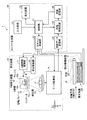
まず、第1の実施形態に係るX線CT装置1の構成について説明する。図1は、第1の実施形態に係るX線CT装置1の構成例を示す図である。図1に示すように、第1の実施形態に係るX線CT装置1は、架台装置10と、寝台装置20と、コンソール装置30とを有する。
(First embodiment)
First, the configuration of the X-ray CT apparatus 1 according to the first embodiment will be described. FIG. 1 is a diagram illustrating a configuration example of an X-ray CT apparatus 1 according to the first embodiment. As shown in FIG. 1, the X-ray CT apparatus 1 according to the first embodiment includes a
架台装置10は、被検体PにX線を照射し、被検体Pを透過したX線を検出して、コンソール装置30に出力する装置であり、X線照射制御部11と、X線発生装置12と、検出器13と、データ収集部14と、回転フレーム15と、架台駆動部16とを有する。
The
回転フレーム15は、X線発生装置12と検出器13とを被検体Pを挟んで対向するように支持し、後述する架台駆動部16によって被検体Pを中心した円軌道にて高速に回転する円環状のフレームである。
The rotating
X線発生装置12は、X線を発生し、発生したX線を被検体Pへ照射する装置であり、X線管12aと、ウェッジ12bと、コリメータ12cとを有する。
The
X線管12aは、図示しない高電圧発生部により供給される高電圧により被検体PにX線ビームを照射する真空管であり、回転フレーム15の回転にともなって、X線ビームを被検体Pに対して照射する。X線管12aは、ファン角及びコーン角を持って広がるX線ビームを発生する。
The
ウェッジ12bは、X線管12aから曝射されたX線のX線量を調節するためのX線フィルタである。具体的には、ウェッジ12bは、X線管12aから被検体Pへ照射されるX線が、予め定められた分布になるように、X線管12aから曝射されたX線を透過して減衰するフィルタである。例えば、ウェッジ12bは、所定のターゲット角度や所定の厚みとなるようにアルミニウムを加工したフィルタである。なお、ウェッジは、ウェッジフィルタ(wedge filter)や、ボウタイフィルタ(bow-tie filter)とも呼ばれる。
The
コリメータ12cは、後述するX線照射制御部11の制御により、ウェッジ12bによってX線量が調節されたX線の照射範囲を絞り込むためのスリットである。
The
X線照射制御部11は、高電圧発生部として、X線管12aに高電圧を供給する装置であり、X線管12aは、X線照射制御部11から供給される高電圧を用いてX線を発生する。X線照射制御部11は、X線管12aに供給する管電圧や管電流を調整することで、被検体Pに対して照射されるX線量を調整する。
The X-ray
また、X線照射制御部11は、ウェッジ12bの切り替えを行なう。また、X線照射制御部11は、コリメータ12cの開口度を調整することにより、X線の照射範囲(ファン角やコーン角)を調整する。なお、本実施形態は、複数種類のウェッジを、操作者が手動で切り替える場合であっても良い。
Further, the X-ray
架台駆動部16は、回転フレーム15を回転駆動させることによって、被検体Pを中心とした円軌道上でX線発生装置12と検出器13とを旋回させる。
The
検出器13は、被検体Pを透過したX線を検出する2次元アレイ型検出器(面検出器)であり、複数チャンネル分のX線検出素子を配してなる検出素子列が被検体Pの体軸方向(図1に示すZ軸方向)に沿って複数列配列されている。具体的には、第1の実施形態における検出器13は、被検体Pの体軸方向に沿って320列など多列に配列されたX線検出素子を有し、例えば、被検体Pの肺や心臓を含む範囲など、広範囲に被検体Pを透過したX線を検出することが可能である。
The
データ収集部14は、検出器13によって検出されたX線を用いて投影データを生成し、生成した投影データをコンソール装置30の投影データ記憶部34に送信する。
The
寝台装置20は、被検体Pを載せる装置であり、図1に示すように、寝台駆動装置21と、天板22とを有する。寝台駆動装置21は、天板22をZ軸方向へ移動して、被検体Pを回転フレーム15内に移動させる。天板22は、被検体Pが載置される板である。
The
なお、架台装置10は、例えば、天板22を移動させながら回転フレーム15を回転させて被検体Pをらせん状にスキャンするヘリカルスキャンを実行する。または、架台装置10は、天板22を移動させた後に被検体Pの位置を固定したままで回転フレーム15を回転させて被検体Pを円軌道にてスキャンするコンベンショナルスキャンを実行する。または、架台装置10は、天板22の位置を一定間隔で移動させてコンベンショナルスキャンを複数のスキャンエリアで行なうステップアンドシュート方式を実行する。
For example, the
コンソール装置30は、操作者によるX線CT装置の操作を受け付けるとともに、架台装置10によって収集された投影データを用いてX線CT画像データを再構成する装置である。コンソール装置30は、図1に示すように、入力装置31と、表示装置32と、スキャン制御部33と、投影データ記憶部34と、画像再構成部35と、画像記憶部36と、制御部37とを有する。
The
入力装置31は、X線CT装置1の操作者が各種指示や各種設定の入力に用いるマウスやキーボード等を有し、操作者から受け付けた指示や設定の情報を、制御部37に転送する。例えば、入力装置31は、操作者から、X線CT画像データの撮影条件や、X線CT画像データを再構成する際の再構成条件や、X線CT画像データに対する画像処理条件等を受け付ける。
The
表示装置32は、操作者によって参照されるモニタであり、制御部37による制御のもと、X線CT画像データを操作者に表示したり、入力装置31を介して操作者から各種指示や各種設定等を受け付けるためのGUI(Graphical User Interface)を表示したりする。
The
スキャン制御部33は、後述する制御部37の制御のもと、X線照射制御部11、架台駆動部16、データ収集部14及び寝台駆動装置21の動作を制御することで、架台装置10における投影データの収集処理を制御する。
The
投影データ記憶部34は、データ収集部14により生成された投影データを記憶する。すなわち、投影データ記憶部34は、X線CT画像データを再構成するための投影データを記憶する。
The projection data storage unit 34 stores the projection data generated by the
画像再構成部35は、投影データ記憶部34が記憶する投影データを用いてX線CT画像データを再構成する。再構成方法としては、種々の方法があり、例えば、逆投影処理が挙げられる。また、逆投影処理としては、例えば、FBP(Filtered Back Projection)法や、コンボリューション逆投影法による逆投影処理が挙げられる。画像再構成部35は、再構成方法として逐次近似法による再構成を実行する。また、画像再構成部35は、X線CT画像データに対して各種画像処理を行なうことで、画像データを生成する。画像再構成部35は、再構成したX線CT画像データや、各種画像処理により生成した画像データを画像記憶部36に格納する。画像記憶部36は、画像再構成部35によって生成された画像データを記憶する。
The
制御部37は、架台装置10、寝台装置20及びコンソール装置30の動作を制御することによって、X線CT装置1の全体制御を行う。具体的には、制御部37は、スキャン制御部33を制御することで、架台装置10で行なわれるCTスキャンを制御する。また、制御部37は、画像再構成部35を制御することで、コンソール装置30における画像再構成処理や画像生成処理を制御する。また、制御部37は、画像記憶部36が記憶する各種画像データを、表示装置32に表示するように制御する。
The
以上、第1の実施形態に係るX線CT装置1の全体構成について説明した。かかる構成のもと、第1の実施形態に係るX線CT装置1は、被ばくの増加を抑止しつつ、観察したい領域の高解像度の画像を得ることを可能にする。ここで、従来技術において、被ばくの増加を抑止しつつ、観察したい領域の高解像度(高分解能)の画像(高精細画像)を得ることが困難となる場合について説明する。一般的に、従来のX線CT装置においては、被ばくの増加を抑止しつつ、観察したい領域(関心領域)について高解像度の画像を得るために、まず、広い領域に対して低線量のX線でスキャンを実行し、スキャンされた領域内で指定された関心領域について高解像度の画像を得るスキャンを実行する。 The overall configuration of the X-ray CT apparatus 1 according to the first embodiment has been described above. Under such a configuration, the X-ray CT apparatus 1 according to the first embodiment makes it possible to obtain a high-resolution image of an area to be observed while suppressing an increase in exposure. Here, a case will be described in which it is difficult to obtain a high-resolution (high-resolution) image (high-definition image) of a region to be observed while suppressing an increase in exposure in the prior art. In general, in a conventional X-ray CT apparatus, in order to obtain a high-resolution image of a region to be observed (region of interest) while suppressing an increase in exposure, first, a low dose X-ray is applied to a wide region. A scan is performed to obtain a high-resolution image for a region of interest designated within the scanned region.
ここで、X線CT装置においては、解像度を調整するために、信号束ね処理や、スライス厚の調整を行う。例えば、信号束ね処理は、検出器における複数の検出素子それぞれで検出されたアナログの信号を、チャンネル方向及びスライス方向のうち少なくとも一方向に所定の単位で合成することであり、この合成単位を変更することにより、解像度を調整する。一例を挙げると、X線CT装置は、4個の検出素子を1単位として合成する標準解像度モードや、合成しない高解像度モードなどを有する。そして、X線CT装置では、広い領域に対して標準解像度モードで低線量のX線でスキャンを実行する。ここで、標準解像度モードにより信号束ね処理を実行することで、S/Nが高くなるため、低線量のX線でスキャンを実行した画像でも十分に観察することができる。 Here, in the X-ray CT apparatus, signal bundling processing and slice thickness adjustment are performed in order to adjust the resolution. For example, the signal bundling process is to synthesize an analog signal detected by each of a plurality of detection elements in a detector in a predetermined unit in at least one of a channel direction and a slice direction, and change the synthesis unit. To adjust the resolution. For example, the X-ray CT apparatus has a standard resolution mode in which four detection elements are combined as one unit, a high resolution mode in which the detection elements are not combined, and the like. In the X-ray CT apparatus, a wide area is scanned with low-dose X-rays in the standard resolution mode. Here, since the S / N is increased by executing the signal bundling process in the standard resolution mode, it is possible to sufficiently observe even an image that has been scanned with a low-dose X-ray.
そして、画像内の関心領域が指定されると、X線CT装置は、指定された領域に対して高解像度モードでのスキャンを実行する。ここで、信号束ね処理を行わない高解像度モードの場合、S/Nが低下するため、S/Nを上げるために高線量のX線でスキャンが実行される。なお、信号束ね処理において、1単位として合成される検出素子数は、上記した例に限られない。 When a region of interest in the image is designated, the X-ray CT apparatus performs a scan in the high resolution mode on the designated region. Here, in the case of the high resolution mode in which the signal bundling process is not performed, the S / N is lowered, so that the scan is executed with a high dose of X-rays in order to increase the S / N. In the signal bundling process, the number of detection elements combined as one unit is not limited to the above example.
また、例えば、スライス厚の調整により解像度を調整する場合、例えば、以下のようにスキャンが実行される。例えば、従来のX線CT装置において、高解像度の画像を収集する場合は、まず広い領域に対して、多列の高ヘリカルピッチ低線量のX線でヘリカルスキャンが実行され、その画像を用いて設定された高解像度が必要な狭い領域に対して、少ない列数の低ヘリカルピッチで比較的高線量条件でのヘリカルスキャンが実行される。高解像度の画像を得るために高いS/Nが必要になるために線量(被ばく)を増やしている。こうして得られた投影データに対して高分解能再構成アルゴリズムを適用して、通常よりも解像度が若干改善されたCT画像を得ている。 For example, when adjusting the resolution by adjusting the slice thickness, for example, the scan is executed as follows. For example, when acquiring a high-resolution image in a conventional X-ray CT apparatus, a helical scan is first performed on a wide area with a multi-row high helical pitch low-dose X-ray, and the image is used. A helical scan under a relatively high dose condition is executed with a low helical pitch with a small number of rows in a narrow area where a high resolution is required. The dose (exposure) is increased because a high S / N is required to obtain a high-resolution image. A high resolution reconstruction algorithm is applied to the projection data thus obtained to obtain a CT image with a slightly improved resolution than usual.
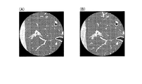
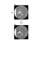
すなわち、X線CT装置においては、まず、信号束ね処理、或いは、高ヘリカルピッチの標準解像度モードで低線量のX線により撮影部位全体の投影データを収集して、収集した投影データから再構成されたCT画像が観察される。例えば、図2の(A)に示すように、標準的な解像度のCT画像が観察される。 That is, in the X-ray CT apparatus, first, projection data of the entire imaging region is collected by signal bundling processing, or low dose X-rays in a standard resolution mode of high helical pitch, and reconstructed from the collected projection data. CT images are observed. For example, as shown in FIG. 2A, a standard resolution CT image is observed.
その後、観察者が所望する場合に、信号束ね処理を行わない、或いは、低ヘリカルピッチの高解像度モードで高線量のX線により収集された投影データからより高解像度なCT画像が再構成されて観察されることとなる。すなわち、図2の(B)に示すように、高解像度のCT画像が観察される。なお、図2は、第1の実施形態に係る解像度の異なるCT画像の一例を示す図である。 Thereafter, if the observer desires, no signal bundling is performed, or a higher resolution CT image is reconstructed from projection data collected by high dose X-rays in a high resolution mode with a low helical pitch. Will be observed. That is, as shown in FIG. 2B, a high-resolution CT image is observed. FIG. 2 is a diagram illustrating an example of a CT image with different resolutions according to the first embodiment.
ここで、投影データを逆投影法によって再構成する場合、関心部位を含むある程度大きな領域の投影データを用いないと、アーチファクトが生じてしまい、観察しやすい高解像度のCT画像が得られない。従って、従来、高解像度モードで投影データを収集する場合には、高い線量のX線が広範囲に照射されることとなり、被ばく量が増加する。そこで、第1の実施形態に係るX線CT装置1は、以下、詳細に説明する制御部37の制御により、被ばくの増加を抑止しつつ、観察したい領域の高解像度の画像を得ることを可能にする。
Here, when the projection data is reconstructed by the backprojection method, if projection data of a certain large area including the region of interest is not used, artifacts occur and a high-resolution CT image that is easy to observe cannot be obtained. Therefore, conventionally, when collecting projection data in the high resolution mode, a high dose of X-rays is irradiated over a wide range, and the exposure dose increases. Therefore, the X-ray CT apparatus 1 according to the first embodiment can obtain a high-resolution image of an area to be observed while suppressing an increase in exposure by the control of the
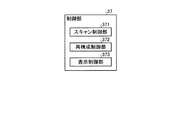
図3は、第1の実施形態に係る制御部37の構成の一例を示す図である。例えば、制御部37は、図3に示すように、スキャン制御部371と、再構成制御部372と、表示制御部373とを有する。スキャン制御部371は、第1のX線照射領域における第1の投影データを収集し、第1のX線照射領域に含まれる第2のX線照射領域における第2の投影データを前記第1の投影データよりも高い解像度で収集する。
FIG. 3 is a diagram illustrating an example of the configuration of the
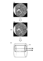
具体的には、スキャン制御部371は、標準解像度モードで被写体全体(断面としての全体であり、スライス方向は一部である)の低線量スキャンを実行させる。ここで、スキャン制御部371は、コリメータがチャンネル方向で全開となるように制御する。図4は、第1の実施形態に係るスキャン制御部371による標準解像度モードでのスキャン制御の一例を示す図である。
Specifically, the
例えば、スキャン制御部371は、図4に示すように、被写体に対してX線管が1回転する際に、断面全体がX線の照射領域となるように、コリメータを開けるように制御する。すなわち、スキャン制御部371は、コリメータをチャンネル方向に絞らずに標準解像度モードによる投影データの収集を実行させる。なお、図示されていないが、スキャン制御部371は、スライス方向に関するコリメータの絞りの制御を適宜実行する。
For example, as shown in FIG. 4, when the X-ray tube makes one rotation with respect to the subject, the
ここで、上述した標準解像度で低線量のX線によるスキャンでは、得られた画像に含まれる関心領域を指定することができる程度の画像であれば、どのようにスキャンされる場合であってもよい。すなわち、スキャン制御部371が、上述した信号束ね処理を行うことで、S/Nを高くし、それによって線量を下げたX線でスキャンを実行する標準解像度モードでのスキャンを実行してもよいが、信号束ね処理を実行せずに、線量を下げるスキャンを実行してもよい。かかる場合には、信号束ね処理を実行せずに線量を下げることによりS/Nが低下してしまい、ノイズの多い画像となってしまう。そこで、スキャン制御部371は、信号束ね処理を実行せずに線量を下げ、得られたノイズの多い画像に対してスムージングフィルタ処理を実行することで、ノイズを低減させて観察しやすい画像を生成するように制御する。なお、スムージングフィルタ処理は、再構成前のデータに対して実行される場合であってもよく、再構成後のデータに実行される場合であってもよい。或いは、再構成前後のデータにそれぞれ実行される場合であってもよい。
Here, in the above-described scan with the low-dose X-rays with the standard resolution, any image can be scanned as long as the region of interest included in the obtained image can be designated. Good. That is, the
ここで、CT画像においては、アナログ信号を処理する回路による電気的なノイズが発生する場合がある。かかるノイズは、画像全体に発生するランダムノイズと比較して、強いノイズとなる場合がある。標準解像度のCT画像を得る場合に、信号束ね処理を実行すると、複数の信号を1つの回路で処理することとなり、このような電気的なノイズの発生を抑えることができる。従って、信号束ね処理を実行すると、このようなノイズの発生を抑えてS/Nを上げることができることから、その分を線量の低減に充てることができる。すなわち、被ばく低減を考慮した場合には、信号束ね処理により標準解像度のCT画像を得ることが望ましい。 Here, in the CT image, electrical noise may be generated by a circuit for processing an analog signal. Such noise may be stronger than random noise generated in the entire image. If a signal bundling process is executed when obtaining a standard-resolution CT image, a plurality of signals are processed by one circuit, and the occurrence of such electrical noise can be suppressed. Therefore, when the signal bundling process is executed, the generation of such noise can be suppressed and the S / N can be increased, so that the amount can be used for reducing the dose. That is, when taking into account exposure reduction, it is desirable to obtain a standard resolution CT image by signal bundling processing.
そして、スキャン制御部371は、標準解像度のCT画像に対して指定された関心領域について、高解像度のCT画像を収集するように制御する。ここで、スキャン制御部371は、高解像度モードの際に、さらにコリメータの制御を実行する。なお、スキャン制御部371による高解像度モードの際の制御については、後に詳述する。
Then, the
図3に戻って、再構成制御部372は、コンボリューション逆投影法により、スキャン制御部371によって収集された標準解像度モードの投影データからCT画像を再構成するように画像再構成部35を制御する。そして、再構成制御部372は、再構成された標準解像度のCT画像を初期画像として、高解像度の投影データを用いた逐次近似法による再構成を実行するように画像再構成部35を制御する。なお、再構成制御部372によって実行される逐次近似法による再構成については後に詳述する。
Returning to FIG. 3, the
表示制御部373は、再構成制御部372の制御によって生成されたCT画像を表示装置32にて表示するように制御する。例えば、表示制御部373は、標準解像度のCT画像を表示装置32に表示させる。ここで、観察者は、表示装置32にて表示されたCT画像を参照して、高解像度で観察したい関心領域を、入力装置31を介して選択する。すなわち、入力装置31は、画像中のノイズを低減するように取得された第1の医用画像内の領域において、第1の医用画像と比較して高解像度(高精細)な第2の医用画像を取得する領域を指定する指定操作を受け付ける。例えば、入力装置31は、第2のX線照射領域を指定する指定操作を受け付ける。図5は、第1の実施形態に係る入力装置31による処理の一例を説明するための図である。ここで、図5の(A)においては、表示装置32にて表示された標準解像度のCT画像を示す。また、図5の(B)においては、操作者によって関心領域が指定されたCT画像を示す。また、図5の(C)は、関心領域の指定領域の一例を示す。
The
例えば、表示制御部373は、図5の(A)に示すように、標準解像度のCT画像を表示装置32に表示させると、入力装置31は、図5の(B)に示すように、観察者から関心領域R1の指定操作を受け付ける。スキャン制御部371は、入力装置31を介して受け付けた関心領域R1の投影データにおける位置を特定する。すなわち、スキャン制御部371は、図5の(C)に示すように、スキャンされた投影データにおけるスライス方向の中心の軸であるZ軸に平行なZ’軸を中心とする関心領域R1の3次元的な領域を特定する。
For example, when the
例えば、スキャン制御部371は、投影データにおける座標情報などに基づいて、領域R1の3次元的な領域を特定する。なお、図5においては、2次元で示したCT画像上に関心領域R1が指定される場合について説明した。しかしながら、実施形態はこれに限定されるものではなく、3次元で示したCT画像上に関心領域R1が指定される場合であってもよい。かかる場合には、例えば、図5の(C)に示すように表示された3次元的なCT画像上で関心領域R1が指定されてもよい。
For example, the
また、関心領域R1の大きさは観察者が任意に設定することができる。また、図5においては、関心領域R1が円(円柱)で指定される場合について示しているが、実施形態はこれに限定されるものではなく、関心領域R1が四角(四角柱)で指定される場合であってもよい。 The size of the region of interest R1 can be arbitrarily set by the observer. FIG. 5 shows the case where the region of interest R1 is designated by a circle (cylindrical), but the embodiment is not limited to this, and the region of interest R1 is designated by a square (square column). It may be the case.
ここで、スキャン制御部371は、Z’軸がZ軸と平行になる領域の指定操作に加えて、Z’軸がZ軸に対して所定の傾きを有するように設定された関心領域R1の位置を特定することも可能である。すなわち、入力装置31は、所定の領域として、3次元の画像データにおけるスライス方向と平行な方向を軸とする領域、又は、3次元の画像データにおけるスライス方向に対して所定の傾きを有する方向を軸とする領域の指定操作を受付ける。図6は、第1の実施形態に係るスキャン制御部371による関心領域の特定の一例を示す図である。
Here, in addition to the operation of designating the region in which the Z ′ axis is parallel to the Z axis, the
例えば、スキャン制御部371は、図6に示すように、投影データのZ軸に対して所定の傾きを有する関心領域R1の投影データにおける位置を特定する。かかる場合には、例えば、表示制御部373は、図6に示すような3次元的なCT画像を表示装置32に表示させる。そして、入力装置31は、図6に示すように、Z軸に対して所定の傾きを備えたZ’軸を基準とする関心領域R1の指定操作を受付ける。
For example, as shown in FIG. 6, the
或いは、表示制御部373が、直交3断面のMPR画像を表示装置32にて表示させ、入力装置31がオブリーク断面の設定を受付ける。これにより、関心領域R1が選択され、スキャン制御部371が、図6に示すように、投影データのZ軸に対して所定の傾きを有する関心領域R1の投影データにおける位置を特定する。
Alternatively, the
上述したように、スキャン制御部371は、投影データのZ軸に対して所定の傾きを有する関心領域R1の投影データにおける位置を特定するが、上記と同様に投影データにおける座標情報などに基づいて、関心領域R1の3次元的な領域を特定する。ここで、スキャン制御部371は、関心領域R1について、Z’軸に直交する断面のサイズ、マトリクスサイズ、Z’軸方向の長さ、Z’軸とZ軸との位置関係(向きや距離など)などの情報を投影データの座標情報から算出して、算出した情報を、各領域を特定するための情報として保持する。
As described above, the
上述したように、標準解像度のCT画像において関心領域R1が指定されると、スキャン制御部371は、指定された関心領域R1に対してX線が照射されるように、スライス方向及びチャンネル方向でX線の照射領域を調整する。図7は、第1の実施形態に係るスキャン制御部371による高解像度モードでのスキャン制御の一例を示す図である。例えば、スキャン制御部371は、図7に示すように、スキャナの回転角度ごとにコリメータの開口位置条件を設定する。
As described above, when the region of interest R1 is specified in the standard resolution CT image, the
ここで、スキャン制御部371は、被写体の体動によって移動する場合を想定したマージンを含む領域がスキャンされるように、スキャナの回転角度ごとにコリメータの開口位置条件を設定する。そして、スキャン制御部371は、設定した条件に従って、スキャナの回転角度ごとにコリメータの開口位置を変化させながら、高解像度モードでスキャンさせ、関心領域R1の投影データを収集する。例えば、スキャン制御部371は、信号束ね処理を行わない高解像度モードで高線量のX線により関心領域R1の投影データを収集する。
Here, the
このように、被ばく低減のためには、スキャナの回転角度毎にコリメータの開口位置をダイナミックに制御することが理想的である。しかしながら、実際には、スキャン速度、制御の速度等によっては、スキャン中に動作させることが難しい場合もある。かかる場合には、コリメータの各ブレードについて、X線管を1回転させた場合の最大開口位置で固定させる場合であってもよい。このような場合でも、標準解像度のスキャンのように全開にするよりはトータルの被ばく量を抑止することができる。また、図7においては、2次元的な領域を想定して説明したが、3次元的に領域を設定した場合、スキャン制御部371は、ビーム厚(スライス厚)を制御するコリメータ(スリット)を同じように動作させる。
Thus, in order to reduce exposure, it is ideal to dynamically control the opening position of the collimator for each rotation angle of the scanner. However, in practice, depending on the scan speed, control speed, etc., it may be difficult to operate during scanning. In such a case, each blade of the collimator may be fixed at the maximum opening position when the X-ray tube is rotated once. Even in such a case, the total exposure amount can be suppressed rather than being fully opened as in a standard resolution scan. In FIG. 7, the description has been made assuming a two-dimensional region. However, when a three-dimensional region is set, the
図7に示したように、関心領域における高解像度モードによるスキャンが実行されると、再構成制御部372は、コンボリューション逆投影法によって再構成させた標準解像度のCT画像を初期画像として、高解像度モードの投影データを用いた逐次近似法による再構成を実行させる。すなわち、再構成制御部372は、標準解像度のCT画像における関心領域の画素に対して、関心領域の投影データを用いて画像を更新する。
As shown in FIG. 7, when scanning in the high resolution mode in the region of interest is performed, the
図8は、第1の実施形態に係る再構成制御部372による処理を模式的に示した図である。例えば、再構成制御部372は、図8の(A)に示すように、標準解像度のCT画像に関心領域R1が指定されると、図8の(B)に示すように、関心領域R1を高解像度のCT画像に更新させるように制御する。例えば、表示制御部373は、図8の(B)に示すCT画像を表示装置32にて表示させるように制御してもよい。
FIG. 8 is a diagram schematically illustrating processing by the
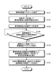
次に、図9を用いて、第1の実施形態に係るX線CT装置の処理について説明する。図9は、第1の実施形態に係るX線CT装置1の処理の一例を説明するためのフローチャートである。 Next, processing of the X-ray CT apparatus according to the first embodiment will be described with reference to FIG. FIG. 9 is a flowchart for explaining an example of processing of the X-ray CT apparatus 1 according to the first embodiment.
例えば、図9に示すように、第1の実施形態に係るX線CT装置1においては、標準解像度でスキャンを実行して(ステップS101)、投影データを用いて標準解像度の画像再構成を実行する(ステップS102)。そして、表示制御部373は、再構成された標準解像度の画像データを表示装置32にて表示させる(ステップS103)。
For example, as shown in FIG. 9, in the X-ray CT apparatus 1 according to the first embodiment, scanning is performed at the standard resolution (step S101), and image reconstruction at the standard resolution is performed using the projection data. (Step S102). Then, the
そして、入力装置31が高解像度の画像を表示する表示領域(例えば、関心領域R1)が指定されたか否かを判定する(ステップS104)。ここで、表示領域が指定されたと判定された場合には(ステップS104肯定)、スキャン制御部371が、選択された領域に対して高解像度でスキャンを実行させる(ステップS105)。
Then, it is determined whether or not a display area (for example, a region of interest R1) in which the
そして、再構成制御部372は、標準解像度の画像を初期画像として、高解像度の投影データを用いて逐次近似再構成を実行する(ステップS106)。表示制御部373は、全体が標準解像度、指定された領域が高解像度の画像データを表示装置32にて表示させる(ステップS107)。
Then, the
上述したように、第1の実施形態によれば、スキャン制御部371は、断面全体における標準解像度の投影データを収集し、断面全体に含まれる関心領域における高解像度の投影データを収集する。そして、再構成制御部372は、スキャン制御部371によって収集された標準解像度の投影データから再構成されたCT画像を初期画像として、関心領域における高解像度の投影データを用いた逐次近似法による再構成を実行する。従って、第1の実施形態に係るX線CT装置1は、高解像度の画像データを得る場合に、関心領域ぎりぎりまで領域を調整することができ、被ばくの増加を抑止しつつ、観察したい領域の高解像度の画像を得ることを可能とする。
As described above, according to the first embodiment, the
また、第1の実施形態によれば、入力装置31は、第2のX線照射領域を指定する指定操作を受け付ける。スキャン制御部371は、入力装置31によって指定操作を受け付けた関心領域に対してX線が照射されるように、スライス方向及びチャンネル方向でX線の照射領域を調整する。従って、第1の実施形態に係るX線CT装置1は、X線の照射を容易に制御することができ、被ばくの増加を抑止しつつ、観察したい領域の高解像度の画像を容易に得ることを可能とする。
Further, according to the first embodiment, the
また、第1の実施形態によれば、スキャン制御部371は、X線が照射されている間、当該X線が関心領域に照射されるように照射領域の調整を継続して実行する。従って、第1の実施形態に係るX線CT装置1は、被ばくを最大限抑止することを可能にする。
Further, according to the first embodiment, the
また、第1の実施形態によれば、再構成制御部372は、コンボリューション逆投影法によって標準解像度の投影データからCT画像を再構成させ、標準解像度のCT画像を初期画像として、高解像度の投影データを用いた逐次近似法による再構成を実行する。従って、第1の実施形態に係るX線CT装置1は、容易に実現することを可能にする。
In addition, according to the first embodiment, the
また、第1の実施形態によれば、表示制御部373は、再構成制御部372によって再構成された全体のCT画像において、関心領域に対応する位置の解像度が全体のCT画像よりも高く示された医用画像を表示部にて表示させるように制御する。従って、第1の実施形態に係るX線CT装置1は、観察者は簡単に観察することを可能にする。
Further, according to the first embodiment, the
(第2の実施形態)
さて、これまで第1の実施形態について説明したが、上記した第1の実施形態以外にも、種々の異なる形態にて実施されてよいものである。
(Second Embodiment)
The first embodiment has been described so far, but may be implemented in various different forms other than the first embodiment described above.
上述した実施形態では、医用画像診断装置の例としてX線CT装置を用いて説明したが、実施形態はこれに限定されるものではなく、例えば、X線診断装置などが用いられる場合であってもよい。 In the above-described embodiment, the X-ray CT apparatus is used as an example of the medical image diagnostic apparatus. However, the embodiment is not limited to this, and for example, an X-ray diagnostic apparatus is used. Also good.
また、上記の第1の実施形態で図示した各装置の各構成要素は機能概念的なものであり、必ずしも物理的に図示の如く構成されていることを要しない。すなわち、各装置の分散・統合の具体的形態は図示のものに限られず、その全部または一部を、各種の負荷や使用状況などに応じて、任意の単位で機能的または物理的に分散・統合して構成することができる。さらに、各装置にて行なわれる各処理機能は、その全部または任意の一部が、CPUおよび当該CPUにて解析実行されるプログラムにて実現され、或いは、ワイヤードロジックによるハードウェアとして実現され得る。 In addition, each component of each device illustrated in the first embodiment is functionally conceptual and does not necessarily need to be physically configured as illustrated. In other words, the specific form of distribution / integration of each device is not limited to that shown in the figure, and all or a part thereof may be functionally or physically distributed or arbitrarily distributed in arbitrary units according to various loads or usage conditions. Can be integrated and configured. Further, all or a part of each processing function performed in each device may be realized by a CPU and a program that is analyzed and executed by the CPU, or may be realized as hardware by wired logic.
また、第1の実施形態で説明した制御方法は、予め用意された制御プログラムをパーソナルコンピュータやワークステーション等のコンピュータで実行することによって実現することができる。この制御プログラムは、インターネット等のネットワークを介して配布することができる。また、この制御プログラムは、ハードディスク、フレキシブルディスク(FD)、CD−ROM、MO、DVD等のコンピュータで読み取り可能な記録媒体に記録され、コンピュータによって記録媒体から読み出されることによって実行することもできる。 Further, the control method described in the first embodiment can be realized by executing a control program prepared in advance on a computer such as a personal computer or a workstation. This control program can be distributed via a network such as the Internet. The control program can also be executed by being recorded on a computer-readable recording medium such as a hard disk, a flexible disk (FD), a CD-ROM, an MO, and a DVD and being read from the recording medium by the computer.
以上、説明したとおり、第1の実施形態及び第2の実施形態によれば、被ばくの増加を抑止しつつ、観察したい領域の高解像度の画像を得ることが可能となる。 As described above, according to the first embodiment and the second embodiment, it is possible to obtain a high-resolution image of an area to be observed while suppressing an increase in exposure.
本発明のいくつかの実施形態を説明したが、これらの実施形態は、例として提示したものであり、発明の範囲を限定することは意図していない。これら実施形態は、その他の様々な形態で実施されることが可能であり、発明の要旨を逸脱しない範囲で、種々の省略、置き換え、変更を行うことができる。これら実施形態やその変形は、発明の範囲や要旨に含まれると同様に、特許請求の範囲に記載された発明とその均等の範囲に含まれるものである。 Although several embodiments of the present invention have been described, these embodiments are presented by way of example and are not intended to limit the scope of the invention. These embodiments can be implemented in various other forms, and various omissions, replacements, and changes can be made without departing from the spirit of the invention. These embodiments and their modifications are included in the scope and gist of the invention, and are also included in the invention described in the claims and the equivalents thereof.
1 X線CT装置
31 入力装置
32 表示装置
37 制御部
371 スキャン制御部
372 再構成制御部
373 表示制御部
1
Claims (7)
前記受付部によって指定操作を受け付けた領域に対応する部位にX線が照射されるように、スライス方向及びチャンネル方向で前記X線の照射領域を調整する制御部と、
前記第1の医用画像を初期画像として、前記制御部によってX線の照射領域が調整され、収集された投影データを用いた逐次近似法による再構成を実行することにより、前記第2の医用画像を取得する再構成制御部と、
を備える、医用画像診断装置。 An accepting unit that accepts a designation operation for designating an area for obtaining a second medical image that is higher in definition than the first medical image in the area in the first medical image;
A control unit that adjusts the X-ray irradiation region in the slice direction and the channel direction so that X-rays are irradiated to the region corresponding to the region for which the designation operation has been received by the reception unit;
By using the first medical image as an initial image, an X-ray irradiation area is adjusted by the control unit, and reconstruction by a successive approximation method using the collected projection data is performed , whereby the second medical image is obtained. A reconstruction control unit for obtaining
A medical image diagnostic apparatus comprising:
前記指定操作を受け付けた領域に対応する部位にX線が照射されるように、スライス方向及びチャンネル方向で前記X線の照射領域を調整し、
前記第1の医用画像を初期画像として、前記X線の照射領域が調整され、収集された投影データを用いた逐次近似法による再構成を実行することにより、前記第2の医用画像を取得する、
ことを含む、制御方法。 In a region in the first medical image, accepting a designation operation for designating a region for obtaining a second medical image having a higher definition than the first medical image;
Adjust the X-ray irradiation area in the slice direction and the channel direction so that X-rays are irradiated to the part corresponding to the area that has received the designation operation,
Using the first medical image as an initial image, the X-ray irradiation area is adjusted , and the second medical image is acquired by executing reconstruction by the successive approximation method using the collected projection data ,
A control method.
Priority Applications (1)
| Application Number | Priority Date | Filing Date | Title |
|---|---|---|---|
| JP2014110585A JP6571313B2 (en) | 2013-05-28 | 2014-05-28 | Medical image diagnostic apparatus and control method |
Applications Claiming Priority (3)
| Application Number | Priority Date | Filing Date | Title |
|---|---|---|---|
| JP2013112332 | 2013-05-28 | ||
| JP2013112332 | 2013-05-28 | ||
| JP2014110585A JP6571313B2 (en) | 2013-05-28 | 2014-05-28 | Medical image diagnostic apparatus and control method |
Publications (2)
| Publication Number | Publication Date |
|---|---|
| JP2015006328A JP2015006328A (en) | 2015-01-15 |
| JP6571313B2 true JP6571313B2 (en) | 2019-09-04 |
Family
ID=51988854
Family Applications (1)
| Application Number | Title | Priority Date | Filing Date |
|---|---|---|---|
| JP2014110585A Active JP6571313B2 (en) | 2013-05-28 | 2014-05-28 | Medical image diagnostic apparatus and control method |
Country Status (3)
| Country | Link |
|---|---|
| US (1) | US10709408B2 (en) |
| JP (1) | JP6571313B2 (en) |
| WO (1) | WO2014192831A1 (en) |
Families Citing this family (13)
| Publication number | Priority date | Publication date | Assignee | Title |
|---|---|---|---|---|
| JP6466085B2 (en) * | 2013-05-27 | 2019-02-06 | キヤノンメディカルシステムズ株式会社 | X-ray CT apparatus and diagnostic imaging apparatus |
| US11020065B2 (en) * | 2013-06-18 | 2021-06-01 | Canon Kabushiki Kaisha | Control device for controlling tomosynthesis imaging, imaging apparatus, imaging system, control method, and program for causing computer to execute the control method |
| JP6498516B2 (en) * | 2015-05-11 | 2019-04-10 | キヤノンメディカルシステムズ株式会社 | Medical image processing apparatus and X-ray CT apparatus |
| JP2017113081A (en) * | 2015-12-21 | 2017-06-29 | 株式会社日立製作所 | X-ray CT apparatus and imaging method |
| EP3459463A1 (en) * | 2017-09-26 | 2019-03-27 | Koninklijke Philips N.V. | Device and method for determining a volume of projection of a dual-axis computed tomography system |
| JP7249567B2 (en) * | 2017-10-27 | 2023-03-31 | 学校法人日本大学 | Dental X-ray CT imaging apparatus and X-ray CT imaging condition setting program |
| EP3476295B1 (en) * | 2017-10-27 | 2020-11-25 | Nihon University | Medical x-ray ct imaging apparatus, medical x-ray ct imaging condition setting method, and x-ray ct imaging condition setting program |
| US20190282189A1 (en) * | 2018-03-15 | 2019-09-19 | Accuray Incorporated | Limiting imaging radiation dose and improving image quality during treatment delivery |
| JP2021053379A (en) * | 2019-09-30 | 2021-04-08 | キヤノンメディカルシステムズ株式会社 | Medical image diagnostic apparatus, ultrasound diagnostic apparatus, medical image system and imaging control method |
| US11322243B2 (en) * | 2019-10-18 | 2022-05-03 | Neosoft, Llc | Method and system for identifying and displaying medical images |
| US11763498B2 (en) * | 2019-11-12 | 2023-09-19 | Shanghai United Imaging Healthcare Co., Ltd. | Systems and methods for image reconstruction |
| GB2590946B (en) | 2020-01-08 | 2023-10-25 | Adaptix Ltd | Apparatus and method of producing a tomogram |
| CN113520426B (en) * | 2021-06-28 | 2023-07-25 | 上海联影医疗科技股份有限公司 | Coaxiality measurement method, medical equipment frame adjustment method, equipment and medium |
Family Cites Families (74)
| Publication number | Priority date | Publication date | Assignee | Title |
|---|---|---|---|---|
| US5541971A (en) * | 1993-09-06 | 1996-07-30 | Kabushiki Kaisha Toshiba | X-ray computerized tomography apparatus |
| JPH1119078A (en) * | 1997-07-09 | 1999-01-26 | Hitachi Medical Corp | X-ray ct device |
| JP3836931B2 (en) * | 1997-03-12 | 2006-10-25 | 株式会社日立メディコ | X-ray CT system with limited irradiation range |
| EP1008325B1 (en) | 1997-03-12 | 2004-10-06 | Hitachi Medical Corporation | X-ray computerized tomograph having collimator which restricts the irradiation range of x-ray fan beam |
| US5907594A (en) * | 1997-07-01 | 1999-05-25 | Analogic Corporation | Reconstruction of volumetric images by successive approximation in cone-beam computed tomography systems |
| JPH1128202A (en) * | 1997-07-10 | 1999-02-02 | Hitachi Medical Corp | X-ray ct |
| JPH11332862A (en) * | 1998-05-27 | 1999-12-07 | Hitachi Medical Corp | X-ray ct apparatus |
| JP4304744B2 (en) * | 1998-11-27 | 2009-07-29 | 株式会社日立メディコ | X-ray CT system |
| JP4349643B2 (en) * | 1999-10-08 | 2009-10-21 | 株式会社日立メディコ | X-ray equipment |
| US6385278B1 (en) * | 2000-04-28 | 2002-05-07 | Ge Medical Systems Global Technology Company, Llc | Method and apparatus for region of interest multislice CT scan |
| JP3977624B2 (en) * | 2001-10-18 | 2007-09-19 | 株式会社東芝 | X-ray computed tomography system |
| US7085343B2 (en) | 2001-10-18 | 2006-08-01 | Kabushiki Kaisha Toshiba | X-ray computed tomography apparatus |
| JP2003153893A (en) | 2001-11-21 | 2003-05-27 | Hitachi Medical Corp | Apparatus for forming tomographic image |
| CN1236731C (en) * | 2001-11-29 | 2006-01-18 | 株式会社东芝 | Computed tomography device |
| US7103134B2 (en) * | 2001-12-28 | 2006-09-05 | Kabushiki Kaisha Toshiba | Computed tomography apparatus |
| US6459755B1 (en) * | 2002-02-26 | 2002-10-01 | Ge Medical Systems Global Technology Co. Llc | Method and apparatus for administering low dose CT scans |
| US6856666B2 (en) * | 2002-10-04 | 2005-02-15 | Ge Medical Systems Global Technology Company, Llc | Multi modality imaging methods and apparatus |
| JP2004180715A (en) * | 2002-11-29 | 2004-07-02 | Toshiba Corp | X-ray computed tomography equipment |
| US7054409B2 (en) * | 2002-12-31 | 2006-05-30 | General Electric Company | Volumetric CT system and method utilizing multiple detector panels |
| JP4490645B2 (en) * | 2003-04-09 | 2010-06-30 | 株式会社東芝 | X-ray computed tomography system |
| JP2004313657A (en) * | 2003-04-21 | 2004-11-11 | Ge Medical Systems Global Technology Co Llc | Radiation computed tomography system |
| JP5242052B2 (en) * | 2003-06-17 | 2013-07-24 | ブラウン ユニバーシティ | Method and apparatus for model-based detection of structures in projection data |
| US7359535B2 (en) * | 2003-06-20 | 2008-04-15 | Ge Medical Systems Global Technology Company, Llc | Systems and methods for retrospective internal gating |
| JP4434698B2 (en) * | 2003-11-13 | 2010-03-17 | 株式会社東芝 | X-ray CT system |
| US7394923B2 (en) * | 2004-02-10 | 2008-07-01 | The University Of Chicago | Imaging system for generating a substantially exact reconstruction of a region of interest |
| US7376255B2 (en) * | 2004-06-23 | 2008-05-20 | General Electric Company | System and method for image reconstruction |
| JP4619704B2 (en) * | 2004-06-30 | 2011-01-26 | 株式会社東芝 | X-ray computed tomography system |
| JP2006014882A (en) * | 2004-06-30 | 2006-01-19 | Samii Kk | Pinball game machine |
| US7272205B2 (en) * | 2004-11-17 | 2007-09-18 | Purdue Research Foundation | Methods, apparatus, and software to facilitate computing the elements of a forward projection matrix |
| EP1731100B9 (en) | 2005-06-06 | 2013-01-23 | Kabushiki Kaisha Toshiba | Medical image display apparatus and medical image display system |
| JP2007014755A (en) * | 2005-06-06 | 2007-01-25 | Toshiba Corp | Medical image display apparatus, medical image generation program, and X-ray computed tomography apparatus |
| US7466790B2 (en) * | 2006-03-02 | 2008-12-16 | General Electric Company | Systems and methods for improving a resolution of an image |
| US7885374B2 (en) * | 2006-03-15 | 2011-02-08 | Kabushiki Kaisha Toshiba | X-ray CT apparatus, a method for changing the helical pitch, an image reconstruction processing apparatus, an image reconstruction processing method, and an image reconstruction processing program |
| JP5007982B2 (en) * | 2006-06-22 | 2012-08-22 | 国立大学法人東北大学 | X-ray CT apparatus, image reconstruction method of the same, and image reconstruction program |
| JP5389324B2 (en) * | 2006-12-18 | 2014-01-15 | ジーイー・メディカル・システムズ・グローバル・テクノロジー・カンパニー・エルエルシー | X-ray tomography equipment |
| US7729467B2 (en) * | 2007-03-22 | 2010-06-01 | General Electric Company | Methods and systems for attentuation correction in medical imaging |
| US9597041B2 (en) * | 2007-03-30 | 2017-03-21 | General Electric Company | Sequential image acquisition with updating method and system |
| US7920670B2 (en) * | 2007-03-30 | 2011-04-05 | General Electric Company | Keyhole computed tomography |
| US7680240B2 (en) * | 2007-03-30 | 2010-03-16 | General Electric Company | Iterative reconstruction of tomographic image data method and system |
| DE102007021023A1 (en) * | 2007-05-04 | 2008-11-13 | Siemens Ag | Imaging method for the variable-pitch spiral CT and CT apparatus for performing the method |
| US8135186B2 (en) * | 2008-01-25 | 2012-03-13 | Purdue Research Foundation | Method and system for image reconstruction |
| US8553959B2 (en) * | 2008-03-21 | 2013-10-08 | General Electric Company | Method and apparatus for correcting multi-modality imaging data |
| CN102036609B (en) * | 2008-05-21 | 2013-03-27 | 皇家飞利浦电子股份有限公司 | Imaging apparatus for generating an image of a region of interest |
| US8139709B2 (en) * | 2008-09-15 | 2012-03-20 | University Of Utah Research Foundation | Staggered circular scans for CT imaging |
| US8649480B2 (en) * | 2009-03-06 | 2014-02-11 | Hitachi Medical Corporation | X-ray CT apparatus and tomography method |
| JP5433334B2 (en) * | 2009-07-27 | 2014-03-05 | 株式会社東芝 | X-ray CT system |
| US8306304B2 (en) * | 2009-08-31 | 2012-11-06 | Siemens Aktiengesellschaft | Precise image reconstruction of spiral CT images at optional pitch values |
| JP5619525B2 (en) * | 2009-09-30 | 2014-11-05 | 株式会社東芝 | X-ray computed tomography apparatus and image processing apparatus |
| US9095259B2 (en) * | 2009-12-04 | 2015-08-04 | Analogic Corporation | Method and system for high resolution nutated slice reconstruction using quarter detector offset |
| US8548118B2 (en) * | 2009-12-21 | 2013-10-01 | General Electric Company | Apparatus and method for spectral projection imaging with fast KV switching |
| US9050003B2 (en) | 2010-03-30 | 2015-06-09 | Hitachi Medical Corporation | Reconstruction computing device, reconstruction computing method, and X-ray CT apparatus |
| JP5727277B2 (en) * | 2010-04-06 | 2015-06-03 | 株式会社東芝 | X-ray CT system |
| US8031828B1 (en) * | 2010-04-30 | 2011-10-04 | General Electric Company | Method and apparatus for computed tomography |
| JP5611663B2 (en) | 2010-05-17 | 2014-10-22 | 株式会社東芝 | X-ray computed tomography apparatus and image processing apparatus |
| JP5813994B2 (en) * | 2010-06-03 | 2015-11-17 | 株式会社東芝 | Medical image diagnostic apparatus and image reconstruction method |
| JP2012013680A (en) | 2010-06-04 | 2012-01-19 | Toshiba Corp | Radiation imaging apparatus, method and program |
| CN102573643B (en) | 2010-10-08 | 2016-04-27 | 株式会社东芝 | Medical image processing device |
| WO2012077694A1 (en) * | 2010-12-10 | 2012-06-14 | 株式会社 日立メディコ | X-ray ct device and image reconstitution method |
| RU2606561C2 (en) * | 2011-01-27 | 2017-01-10 | Конинклейке Филипс Электроникс Н.В. | Truncation compensation for iterative reconstruction in computed tomography (ct) with conical beam in combined spect/ct systems |
| JP5726288B2 (en) * | 2011-03-22 | 2015-05-27 | 株式会社日立メディコ | X-ray CT apparatus and method |
| EP2691932B1 (en) * | 2011-03-28 | 2019-07-24 | Koninklijke Philips N.V. | Contrast-dependent resolution image |
| JP6165438B2 (en) * | 2012-01-27 | 2017-07-19 | 東芝メディカルシステムズ株式会社 | X-ray CT system |
| IN2014DN05824A (en) * | 2012-04-24 | 2015-05-15 | Hitachi Medical Corp | |
| US9237874B2 (en) * | 2012-04-30 | 2016-01-19 | General Electric Company | Method and system for non-invasive imaging of a target region |
| JP2014042564A (en) * | 2012-08-24 | 2014-03-13 | Sony Corp | Image processing apparatus, image processing method, and image processing system |
| US9696452B2 (en) * | 2012-11-02 | 2017-07-04 | Analogic Corporation | Volumetric and projection image generation |
| JP6218334B2 (en) * | 2012-11-30 | 2017-10-25 | 株式会社日立製作所 | X-ray CT apparatus and tomographic imaging method thereof |
| WO2014104306A1 (en) * | 2012-12-27 | 2014-07-03 | 株式会社東芝 | X-ray ct device and control method |
| CN103913472B (en) * | 2012-12-31 | 2016-04-20 | 同方威视技术股份有限公司 | Ct imaging system and method |
| DE102013200337B4 (en) * | 2013-01-11 | 2021-11-11 | Siemens Healthcare Gmbh | Method, computer tomograph and computer program product for determining intensity values of an X-ray radiation for dose modulation |
| US9672640B2 (en) * | 2013-01-24 | 2017-06-06 | Varian Medical Systems International Ag | Method for interactive manual matching and real-time projection calculation in imaging |
| CA2906973C (en) * | 2013-04-04 | 2020-10-27 | Illinois Tool Works Inc. | Helical computed tomography |
| US9826952B2 (en) * | 2013-05-24 | 2017-11-28 | Hitachi, Ltd. | X-ray CT apparatus and scanning method |
| JP6466085B2 (en) * | 2013-05-27 | 2019-02-06 | キヤノンメディカルシステムズ株式会社 | X-ray CT apparatus and diagnostic imaging apparatus |
-
2014
- 2014-05-28 WO PCT/JP2014/064179 patent/WO2014192831A1/en not_active Ceased
- 2014-05-28 JP JP2014110585A patent/JP6571313B2/en active Active
-
2015
- 2015-11-27 US US14/953,203 patent/US10709408B2/en active Active
Also Published As
| Publication number | Publication date |
|---|---|
| JP2015006328A (en) | 2015-01-15 |
| US10709408B2 (en) | 2020-07-14 |
| WO2014192831A1 (en) | 2014-12-04 |
| US20160073974A1 (en) | 2016-03-17 |
Similar Documents
| Publication | Publication Date | Title |
|---|---|---|
| JP6571313B2 (en) | Medical image diagnostic apparatus and control method | |
| JP6466085B2 (en) | X-ray CT apparatus and diagnostic imaging apparatus | |
| JP6688557B2 (en) | X-ray CT system | |
| US8396184B2 (en) | X-ray CT system and control method for same | |
| US10111626B2 (en) | X-ray CT apparatus | |
| JP4646810B2 (en) | Tomographic image reconstruction method and tomographic apparatus | |
| EP2446821B1 (en) | Dynamic collimator for wide coverage and low dose cardiac CT imaging | |
| JP5406063B2 (en) | Reconstruction calculation device, reconstruction calculation method, and X-ray CT apparatus | |
| JP2004180715A (en) | X-ray computed tomography equipment | |
| JPWO2012077694A1 (en) | X-ray CT apparatus and image reconstruction method | |
| JP7462433B2 (en) | Medical diagnostic system, medical diagnostic device, and medical information processing device | |
| US20170215818A1 (en) | High-resolution computed tomography or c-arm imaging | |
| JP6615524B2 (en) | X-ray CT apparatus and image processing apparatus | |
| JP2007300964A (en) | Radiographic equipment and radiography method | |
| JP4469555B2 (en) | X-ray computed tomography system | |
| JP6615439B2 (en) | X-ray CT system | |
| JP7619869B2 (en) | Medical image processing method, medical image processing device, and X-ray CT device | |
| JP2009089810A (en) | X-ray ct system | |
| JP2018020112A (en) | X-ray CT apparatus | |
| JP6466057B2 (en) | Medical diagnostic imaging equipment | |
| JPWO2016132880A1 (en) | Arithmetic apparatus, X-ray CT apparatus, and image reconstruction method | |
| JP4406106B2 (en) | X-ray CT system | |
| JP7370802B2 (en) | Medical image processing equipment and X-ray CT equipment | |
| JP7177613B2 (en) | X-ray CT device | |
| JP2005334230A (en) | Radiation ct equipment and image reconstruction method using the same |
Legal Events
| Date | Code | Title | Description |
|---|---|---|---|
| RD01 | Notification of change of attorney |
Free format text: JAPANESE INTERMEDIATE CODE: A7421 Effective date: 20151102 |
|
| A711 | Notification of change in applicant |
Free format text: JAPANESE INTERMEDIATE CODE: A711 Effective date: 20160513 |
|
| RD02 | Notification of acceptance of power of attorney |
Free format text: JAPANESE INTERMEDIATE CODE: A7422 Effective date: 20160929 |
|
| RD04 | Notification of resignation of power of attorney |
Free format text: JAPANESE INTERMEDIATE CODE: A7424 Effective date: 20161021 |
|
| A621 | Written request for application examination |
Free format text: JAPANESE INTERMEDIATE CODE: A621 Effective date: 20170516 |
|
| A131 | Notification of reasons for refusal |
Free format text: JAPANESE INTERMEDIATE CODE: A131 Effective date: 20180522 |
|
| A521 | Request for written amendment filed |
Free format text: JAPANESE INTERMEDIATE CODE: A523 Effective date: 20180723 |
|
| A131 | Notification of reasons for refusal |
Free format text: JAPANESE INTERMEDIATE CODE: A131 Effective date: 20181211 |
|
| A521 | Request for written amendment filed |
Free format text: JAPANESE INTERMEDIATE CODE: A523 Effective date: 20190208 |
|
| TRDD | Decision of grant or rejection written | ||
| A01 | Written decision to grant a patent or to grant a registration (utility model) |
Free format text: JAPANESE INTERMEDIATE CODE: A01 Effective date: 20190709 |
|
| A61 | First payment of annual fees (during grant procedure) |
Free format text: JAPANESE INTERMEDIATE CODE: A61 Effective date: 20190808 |
|
| R150 | Certificate of patent or registration of utility model |
Ref document number: 6571313 Country of ref document: JP Free format text: JAPANESE INTERMEDIATE CODE: R150 |