US7885374B2 - X-ray CT apparatus, a method for changing the helical pitch, an image reconstruction processing apparatus, an image reconstruction processing method, and an image reconstruction processing program - Google Patents
X-ray CT apparatus, a method for changing the helical pitch, an image reconstruction processing apparatus, an image reconstruction processing method, and an image reconstruction processing program Download PDFInfo
- Publication number
- US7885374B2 US7885374B2 US11/685,985 US68598507A US7885374B2 US 7885374 B2 US7885374 B2 US 7885374B2 US 68598507 A US68598507 A US 68598507A US 7885374 B2 US7885374 B2 US 7885374B2
- Authority
- US
- United States
- Prior art keywords
- image
- area
- data
- biological signal
- reconstructed
- Prior art date
- Legal status (The legal status is an assumption and is not a legal conclusion. Google has not performed a legal analysis and makes no representation as to the accuracy of the status listed.)
- Active, expires
Links
Images


Classifications
-
- A—HUMAN NECESSITIES
- A61—MEDICAL OR VETERINARY SCIENCE; HYGIENE
- A61B—DIAGNOSIS; SURGERY; IDENTIFICATION
- A61B6/00—Apparatus for radiation diagnosis, e.g. combined with radiation therapy equipment
- A61B6/02—Devices for diagnosis sequentially in different planes; Stereoscopic radiation diagnosis
- A61B6/03—Computerised tomographs
- A61B6/032—Transmission computed tomography [CT]
-
- A—HUMAN NECESSITIES
- A61—MEDICAL OR VETERINARY SCIENCE; HYGIENE
- A61B—DIAGNOSIS; SURGERY; IDENTIFICATION
- A61B6/00—Apparatus for radiation diagnosis, e.g. combined with radiation therapy equipment
- A61B6/02—Devices for diagnosis sequentially in different planes; Stereoscopic radiation diagnosis
- A61B6/027—Devices for diagnosis sequentially in different planes; Stereoscopic radiation diagnosis characterised by the use of a particular data acquisition trajectory, e.g. helical or spiral
-
- A—HUMAN NECESSITIES
- A61—MEDICAL OR VETERINARY SCIENCE; HYGIENE
- A61B—DIAGNOSIS; SURGERY; IDENTIFICATION
- A61B6/00—Apparatus for radiation diagnosis, e.g. combined with radiation therapy equipment
- A61B6/48—Diagnostic techniques
- A61B6/488—Diagnostic techniques involving pre-scan acquisition
-
- A—HUMAN NECESSITIES
- A61—MEDICAL OR VETERINARY SCIENCE; HYGIENE
- A61B—DIAGNOSIS; SURGERY; IDENTIFICATION
- A61B6/00—Apparatus for radiation diagnosis, e.g. combined with radiation therapy equipment
- A61B6/50—Clinical applications
- A61B6/504—Clinical applications involving diagnosis of blood vessels, e.g. by angiography
-
- A—HUMAN NECESSITIES
- A61—MEDICAL OR VETERINARY SCIENCE; HYGIENE
- A61B—DIAGNOSIS; SURGERY; IDENTIFICATION
- A61B6/00—Apparatus for radiation diagnosis, e.g. combined with radiation therapy equipment
- A61B6/54—Control of apparatus or devices for radiation diagnosis
- A61B6/541—Control of apparatus or devices for radiation diagnosis involving acquisition triggered by a physiological signal
-
- A—HUMAN NECESSITIES
- A61—MEDICAL OR VETERINARY SCIENCE; HYGIENE
- A61B—DIAGNOSIS; SURGERY; IDENTIFICATION
- A61B5/00—Measuring for diagnostic purposes; Identification of persons
- A61B5/24—Detecting, measuring or recording bioelectric or biomagnetic signals of the body or parts thereof
- A61B5/316—Modalities, i.e. specific diagnostic methods
- A61B5/318—Heart-related electrical modalities, e.g. electrocardiography [ECG]
- A61B5/346—Analysis of electrocardiograms
- A61B5/349—Detecting specific parameters of the electrocardiograph cycle
- A61B5/352—Detecting R peaks, e.g. for synchronising diagnostic apparatus; Estimating R-R interval
-
- A—HUMAN NECESSITIES
- A61—MEDICAL OR VETERINARY SCIENCE; HYGIENE
- A61B—DIAGNOSIS; SURGERY; IDENTIFICATION
- A61B6/00—Apparatus for radiation diagnosis, e.g. combined with radiation therapy equipment
- A61B6/40—Apparatus for radiation diagnosis, e.g. combined with radiation therapy equipment with arrangements for generating radiation specially adapted for radiation diagnosis
- A61B6/4064—Apparatus for radiation diagnosis, e.g. combined with radiation therapy equipment with arrangements for generating radiation specially adapted for radiation diagnosis specially adapted for producing a particular type of beam
- A61B6/4085—Cone-beams
Definitions
- the present invention relates to a technology for emitting an X-ray while changing the helical pitch so as to obtain transmission data for a subject to be examined, reconstructing an image of the subject to be examined from the obtained transmission data.
- the X-ray CT apparatus emits X-rays, detects X-rays transmitted through the subject to be examined, and reconstructs the image of the inside of the subject to be examined from projection data indicating the intensity of detected X-rays. It plays an important role in medical practices such as diagnosing diseases, treatment, planning surgery, and so forth.
- This X-ray CT apparatus has a variety of imaging methods, depending on the type of diagnostic imaging, including the method of administering a contract agent to the subject to be examined and then obtaining the image and the method of reconstructing the image in synchronization with the biological signal, for example. In any case, it is essential to obtain an image that is accurate enough for diagnostic imaging and to reconstruct the same.
- a pre-scan is performed, and then a scan is initiated after detecting that the contract agent has flowed into the area of which the image is to be reconstructed by this pre-scan.
- a pre-scan is repeated before the scan. This pre-scan scans part of the reconstruction area of an image with a lower radiation dose than the actual scan and determines concentration of contract agent flowing into the reconstruction area of an image depending upon the CT value of the obtained image.
- concentration of the contract agent reaches a certain point, the scan is initiated.
- the method of automatically determining the concentration of the contract agent by way of a predetermined threshold value and then automatically initiating the scan is referred to a “real prep-scan” (e.g., cf. Japanese Patent laid-open No. 2003-245275).
- FIG. 1 This real-prep scanning by a conventional X-ray CT apparatus is shown in FIG. 1 .
- an X-ray tube is positioned for a pre-scan at a point within the reconstruction area of the image, and then X-rays is emitted at the pre-scan position Z 0 to obtain a pre-scan image.
- This pre-scan image is a tomographic image. Once the pre-scan image is obtained, the CT value of this image is calculated, and if it is at the threshold value or greater, the scan can be initiated.
- the bed is moved so that X-ray tube is positioned outside the reconstruction area of the image, and then a margin is set outside the starting edge of the reconstruction area of the image.
- the scan is initiated from this margin area toward the ending edge of the reconstruction area of the image by the helical scan.
- the reason to set the margin is that X-rays for the number of views (BPview) required for reconstruction of the image is also emitted at the starting edge position of the image reconstruction by a helical scan.
- the real prep-scan For the real prep-scan, it is essential to scan at the time when the contract agent administered to the subject to be examined is flowing into the reconstruction area of the image. Therefore, it is important to perform the scan immediately after the pre-scan detects that the contract agent has flowed into the area. This is because, if the contract agent flows out of the reconstruction area of the image or is lost and the necessary concentration of the contract agent thus cannot be obtained, an image with superior quality cannot be reconstructed.
- X-ray tube when the pre-scan detects the flow of the contract agent, X-ray tube must be placed outside the reconstruction area of the image, the margin must be formed, and the scan must then be initiated from this margin.
- the initiation of the scan for the reconstruction area of the image must be suspended from the time of detection of flowing of the contract agent due to this margin setting and the scan of the margin. Accordingly, with a conventional real prep-scan, an image with sufficient accuracy is not necessarily reconstructed. Furthermore, X-rays is emitted at the area that corresponds to the margin as well, so the subject to be examined will be affected by exposure even when he is outside the reconstruction area of the image, which is also not desirable for the subject to be examined.
- diagnostic imaging includes an approach to diagnose only the region of interest and an approach to diagnose a larger area e.g. searching the affected area from the entire body.
- the reconstruction area of the image may include an area involving physical movement such as from the heart, lungs, and so forth, and an area without such physical movement.
- the physical movement corresponds to the movement of activities of the body system. Between the area involving physical movement and areas without physical movement, the method of obtaining data required to reconstruct the image for that area is different.
- a biological signal synchronization reconstruction method that is characteristic of the method of obtaining data required for reconstruction is used (e.g., cf. Japanese Patent laid-open No. 2005-66042).
- biological signal data showing changes in the physical movement is obtained in synchronization with the imaging of a subject to be examined, and then, partial data obtained while obtaining the biological signal data showing movement of a particular phase is extracted from projection data and gathered, and then the gathered data is used to reconstruct the image.
- the helical pitch is limited to the pitch that passes the area involving an area of physical movement when multiple cycles of a changing biological signal are repeated, in order to gather multiple sets of data showing the physical movement of the particular phase.
- FIG. 2 is a view showing a method of imaging a conventional area including an area involving physical movement and an area without physical movement.
- the reconstruction area SE which involves physical movement and is reconstructed in synchronization with the biological signal, is included in the entire reconstruction area of the image and is situated between reconstruction areas NSE that do not involve physical movement and are reconstructed in asynchronization with the biological signal.
- the first scan images one of the reconstruction areas NSE that is reconstructed in asynchronization with the biological signal.
- it images the reconstruction area SE that is reconstructed in synchronization with the biological signal by a second scan.
- the present invention relates to technology that forms an image of the inside of a subject to be examined from transmission data of the subject to be examined obtained by emitting X-rays, and is intended to provide technology that enables reconstruction of an image with superior quality that is effective in the application of diagnosis and also reduces the risk of the subject to be examined being exposed to excessive amounts of radiation.
- a pre-scan reconstructs a pre-scan image of the subject to be examined from transmission data based on X-rays detected by the detector. Based on changes in the CT value of the reconstructed pre-scan image, it is determined whether to initiate the scan. Based on this determination result, the scan is performed by directly changing the helical pitch from the stopped position of the bed for the pre-scan to the position toward the ending edge of the reconstruction area of the image, and then the scan image of the subject to be examined is reconstructed from the transmission data based on X-rays detected by the detector via the scan.
- the scan is initiated at the first helical pitch that enables the emission of X-rays for a predetermined number of views to the starting edge of the reconstruction area of the image, and after emitting X-rays for the predetermined number of views, the pitch is switched to a predetermined second helical pitch for continuation of the scan.
- the margin is not needed to be set outside the reconstruction area of the image to obtain the image of the starting edge position, so unnecessary risk from radiation is thereby prevented. Furthermore, because the margin is set outside the bed, it is not needed to be moved backward once to form the margin outside the reconstruction area of the image, thus allowing initiation of the scan immediately after the pre-scan. Therefore, after detecting flowing of the contract agent, the scan can be initiated quickly, and an image with high accuracy can be reconstructed as a result of the contract effect from the contract agent.
- a predetermined number of views may be the number of views necessary to reconstruct an image at the starting edge of the reconstruction area of the image.
- it may be the number of views that is insufficient for construction of the image at the starting edge of the reconstruction area of the image if initiating the scan at the second helical pitch, and the first helical pitch may be the maximum pitch at which X-rays for the number of insufficient views can be emitted.
- it may be the number of views that is insufficient for construction of the image at the starting edge of the reconstruction area of the image if initiating the scan at the second helical pitch, and the value of the first helical pitch may be 0.
- the first helical pitch at which X-rays for the predetermined number of views to the starting edge of the reconstruction area of the image can be emitted may be calculated.
- the image for the zone where the helical pitch is being changed may also be reconstructed.
- the second embodiment of the present invention first stores transmission data of the subject to be examined obtained by a continuous single helical scan and the biological signal data of the subject to be examined obtained during said helical scan in a correlated way. Then, the transmission data is segmented into a first transmission data that corresponds to the area to be reconstructed in synchronization with said biological signal and the second transmission data that corresponds to the area to be reconstructed in asynchronization with said biological signal. Next, based on said biological signal data and said first transmission data, while overlapping in the vicinity of the two boundaries, the image of the subject to be examined is reconstructed, in asynchronization with said biological signal data, and then the image of the subject to be examined is reconstructed from said second transmission data. Afterward, a combined image is formed in which the image reconstructed in synchronization with the biological signal and the image reconstructed in asynchronization with the biological signal are combined with weighting addition at the partly overlapped area.
- the second embodiment of the present invention when the scan is performed simultaneously for both the area involving physical movement and the area not involving physical movement, no time lag will be incurred over these areas, and the entire image can also be reconstructed without leading to inaccurate data around the area involving physical movement. Additionally, an image with superior quality can be obtained, without performing multiple scans, which also reduces the risk of effects from unnecessary radiation.
- FIG. 1 shows a real preparatory scan by a conventional X-ray CT apparatus.
- FIG. 2 shows technology for imaging the conventional area including an area with physical movement and an area without physical movement.
- FIG. 3 shows the structure that controls the variable helical scan by X-ray CT apparatus according to the present embodiment.
- FIG. 4 is a pattern diagram that shows a screen for setting imaging conditions.
- FIG. 5 shows the method of calculating the first helical pitch HP new .
- FIG. 6 shows an operation of creating data for the HP-distance sequence.
- FIG. 7 is a block diagram that shows the overall structure of an X-ray CT apparatus according to the present embodiment.
- FIG. 8 is a flowchart that shows how projection data is obtained in accordance with the HP-distance sequence of the X-ray CT apparatus.
- FIG. 9 is a graph that shows the helical pitch for the overall reconstruction area of the image.
- FIG. 10 shows the method of calculating the number of views for a variable helical scan with a helical pitch value of 0.
- FIG. 11 shows how the scan area is created for a helical scan with a pitch value of 0.
- FIG. 12 is a flowchart that shows the initial operations of obtaining projection data, including a first helical pitch of 0 in accordance with the HP-distance sequence.
- FIG. 13 is a graph that shows the helical pitch for initial operations.
- the vertical axis thereof shows the helical pitch, and the horizontal axis shows the time.
- FIG. 14 is a block diagram that shows the structure of the image reconstruction processing apparatus, which is an embodiment of the image reconstruction processing technology according to the present embodiment.
- FIG. 15 is a block diagram that shows the functions of this image reconstruction processing apparatus.
- FIG. 16 is a diagram that shows projection data stored in the projection data storage unit as well as the biological signal data.
- FIG. 17 shows pattern diagrams of the biological signal synchronization reconstruction method.
- FIG. 18 shows pattern diagrams of reconstruction in asynchronization with the biological signal.
- FIG. 19 is a diagram that shows the feathering process.
- FIG. 20 is a flowchart that shows the operation of the image reconstruction process.
- FIG. 3 shows the structure for controlling the variable helical scan by a X-ray CT apparatus according to the present embodiment.
- the X-ray CT apparatus includes a scanning part 110 , a CPU unit 121 , and a scan-controlling unit 122 .
- An input unit 123 , a monitor 124 , and an image forming unit 125 are connected to the CPU unit 121 to enable data input/output.
- the CPU unit 121 includes a pre-scan-determining unit 121 a and a sequence-creating unit 121 b.
- This X-ray CT apparatus obtains, via a real prep-scan, an image of the reconstruction area of the image. First, it performs a pre-scan and then detects flowing of the contract agent to the reconstruction area of the image.
- the reconstruction area of the image is the area for which an image of the subject to be examined is to be reconstructed.
- the pre-scan in order to detect that the contract agent has reached the reconstruction area of the image, so part of the reconstruction area of the image is scanned with low-dose radiation.
- the CT value of the pre-scan image obtained with the low-dose radiation is monitored, and when the CT value reaches the predetermined threshold value, a scan of the reconstruction area of the image is initiated.
- the image in which the contract agent is used will have a higher CT value, so if the CT value exceeds the threshold value, it can be detected that the contract agent has reached the reconstruction area of the image.
- the scan is performed by emitting X-rays via a variable helical scan to obtain a scan image of the reconstruction area of the image.
- the X-ray CT apparatus When the pre-scan detects the flow of the contract agent, the X-ray CT apparatus begins to image the reconstruction area of the image via a variable helical scan. This X-ray CT apparatus, following the completion of the pre-scan, directly initiates a variable helical scan toward the ending edge of the margin without forming the margin.
- the variable helical scan emits X-rays while changing the helical pitch during a series of scans from the starting edge to the ending edge of the area to be imaged.
- the helical pitch is defined as the distance of movement in the direction of the axis of the subject to be examined while emitting X-rays once from the entire circumference. If displacement of the emitting angle changes at a particular speed, the helical pitch is the displacement speed in the slicing direction, and if the displacement speed in the slicing direction is zero, the helical pitch will be 0.
- the margin refers to the X-ray emission area extending from the starting edge position of the image reconstruction to outside the reconstruction area of the image. Specifically, it refers to, in contrast to the starting edge position of the reconstruction area of the image, a particular area from the starting edge position of image reconstruction to outside of the reconstruction area of the image for the number of views required to reconstruct the image (hereinafter referred to as “BPview”).
- the margin is, in a conventional X-ray CT apparatus, set to ensure the emission of X-rays for the BPview to the starting edge position of the reconstruction area of the image while continuously moving the scanning position in an axis of the subject to be examined's body via a helical scan.
- BPview refers to the number of views required to reconstruct an image, which is the number of X-ray emissions for the predetermined angular range. This BPview depends on reconstruction methods such as the 360-degree interpolation method, the 180-degree interpolation method, the opposing beam interpolation method, the 180-degree extrapolation method, and so forth. For example, BPview is the number of views that X-rays are emitted from the angular range of 180 degrees or greater.
- This X-ray CT apparatus calculates the initial helical pitch HP new (first helical pitch), which can ensure X-ray emission for the BPview to the starting edge position of the image reconstruction, and also controls transition timing to this initial helical pitch and predetermined helical pitch HP org (second helical pitch).
- the scanning part 110 while moving the subject to be examined in the direction of the axis of the body, emits X-rays around the body axis, and then detects X-rays transmitted through the subject to be examined to obtain the transmission data.
- That transmission data is the data resulting from the detection of X-rays transmitted through the subject to be examined.
- the scan-controlling unit 122 controls the drive of this scanning part 110 . More specifically, it controls the dose of X-ray radiation or the helical pitch and so forth.
- the image forming unit 125 pre-processes raw data obtained by detecting X-rays transmitted by the subject to be examined to form the projection data and performs a reconstruction process on this projection data to reconstruct the image of the subject to be examined.
- the transmission data collectively refers to this raw data and the projection data.
- the CPU unit 121 is a computer in which a central processing unit (CPU), a random access memory (RAM), and a hard-disk drive (HDD) are interconnected via a bus (BUS) to enable mutual data input/output.
- CPU central processing unit
- RAM random access memory
- HDD hard-disk drive
- BUS bus
- the CPU unit 121 inputs control data into the scan-controlling unit 122 .
- the scan-controlling unit 122 changes the dose of X-ray radiation or the helical pitch of the scanning part 110 .
- the control data includes the dose of X-ray radiation emitted at the subject to be examined and the HP-distance sequence.
- the HP-distance sequence is the data that relates the helical pitch for the variable helical scan to the distance the bed moves at the helical pitch.
- the CPU unit 121 at the time of the pre-scan, inputs the control data for a pre-scan into the scan-controlling unit 122 , and at the time of the variable helical scan, inputs the control data for the variable helical scan into the scan-controlling unit 122 .
- a pre-scan-determining unit 121 a inputs the control data of the pre-scan into the scan-controlling unit 122 and monitors initiation of the variable helical scan. Then, when it reaches the timing in which the variable helical scan begins, the pre-scan-determining unit 121 a inputs a trigger signal into the scan-controlling unit 122 to switch between pre-scan and scan.
- the pre-scan-determining unit 121 a monitors flowing of the contract agent into the reconstruction area of the image.
- the pre-scan by the scanning part 110 allows calculation of the CT value of the image formed by the image forming unit 125 . When the calculated CT value exceeds the threshold value, the trigger signal is inputted, which causes the scan-controlling unit 122 to scan via a variable helical scan.
- the threshold value is stored in the external storage unit in advance.
- switching between pre-scan and scan may be automatically performed by the pre-scan-determining unit 121 a as a result of comparison of the CT value and the threshold value. Alternatively, it may be performed by pressing the switch button based on the displayed graph, which is shown on the monitor 124 , indicating CT values of the image in chronological order.
- the switch button is allocated to the button designated on the input unit 123 . When this switch button is pressed down, the trigger signal is input into the scan-controlling unit 122 .
- the sequence-creating unit 121 b creates data for the HP-distance sequence and inputs it to the scan-controlling unit 122 .
- Control data for the scan including data for this HP-distance sequence is input into the scan-controlling unit 122 prior to the pre-scan.
- Data for the HP-distance sequence is generated in accordance with the imaging conditions input by the input unit 123 .
- the sequence-creating unit 121 b displays the setting screen for the imaging conditions on the monitor 124 at the time of inputting imaging conditions using the input unit 123 .
- FIG. 4 is a pattern diagram that shows the setting screen of the imaging conditions.
- the screen displays the pattern diagram (model) SG of the subject to be examined.
- This pattern diagram SG is a scanogram that has been imaged in advance for determining a position of slice.
- the operator specifies the entire reconstruction area of the image, which begins from the starting edge position Z 1 of the image reconstruction; the reconstruction area SE, which is reconstructed in synchronization with the biological signal among the entire reconstruction area of the image; and the reconstruction area NSE, which is reconstructed in asynchronization with the biological signal; and the pre-scan position Z 0 for performing the scan.
- the input unit 123 is used to specify the first reconstruction area of the image including the starting edge position Z 1 of the image reconstruction, and then the first reconstruction area of the image is specified as the reconstruction area NSE.
- the input unit 123 is used to specify the second reconstruction area of the image that follows the first reconstruction area of the image, and then the second reconstruction area of the image is specified as the reconstruction area SE.
- the third reconstruction area of the image that follows the second reconstruction area of the image is specified, and then the third reconstruction area of the image is specified as reconstruction area NSE.
- the input unit 123 is again used to specify the pre-scan position Z 0 .
- the sequence-creating unit 121 b reflecting the operation used in this input unit 123 , displays distinctly on the monitor 124 , first to third areas to reconstruct the image and the reconstruction area SE or the reconstruction area NSE of its respective areas to reconstruct the image and then displays the pre-scan position Z 0 .
- FIG. 5 shows the method of calculating the first helical pitch HP new via a sequence-creating unit 121 b .
- the vertical axis shows the position Z along the body axis, while the horizontal axis is a view.
- FIG. 5 shows that the area along the body axis is radiated with X-rays according to the view.
- the sequence-creating unit 121 b calculates HP new , which enables the emission of X-rays for at least BPview to the starting edge position Z 1 of the image reconstruction, and the bed movement distance D at that HP new . This calculation is based on the X-ray emission width DW for the scan, a positional relationship between the starting edge position Z 1 of the image reconstruction and pre-scan position Z 0 , BPView, and the predetermined HP org .
- Views (Z 1 ) the number of views used to reconstruct the starting edge position Z 1 of the image reconstruction (referred to as Views (Z 1 )) to satisfy the following (Equation 1). This is because, if X-rays cannot be emitted at the starting edge position Z 1 of the image reconstruction with at least the number of views of BP view , the image of the starting edge position Z 1 of the image reconstruction cannot be reconstructed. Views( Z 1 ) ⁇ BP view (Equation 1)
- the pre-scan position Z 0 is generally positioned at the center of the X-ray emission range at the beginning of the scan so as to scan with a small radiation dose. Furthermore, Z 0 ⁇ DW/2 is the edge position DE of the X-ray emission range on the side of starting edge position Z 1 of the image reconstruction, while Z 1 ⁇ (Z 0 ⁇ DW/2) is the interval between the edge position DE and the starting edge position Z 1 of the image reconstruction. In short, DW/2 ⁇ (
- Equation 2 shows the Views(Z 1 ) that are ensured until the edge position DE reaches the starting edge position Z 1 of the image reconstruction, because the X-ray emission range extends between the edge position DE at the time of initiating the scan and the starting edge position Z 1 of the image reconstruction at the moving angle of ⁇ .
- Equation 4 is derived from the above-mentioned (Equation 1), (Equation 2), and (Equation 3). f ( HP ) ⁇ DW/ 2 ⁇ (
- the sequence-creating unit 121 b calculates DW/2 ⁇ (
- this predetermined HP org performs the helical scan at HP org from the beginning of the scan.
- This predetermined HP org is input by using the input unit 123 .
- the reconstruction area of the image including the starting edge position Z 1 of the image reconstruction is the reconstruction area SE that is to be reconstructed in synchronization with the biological signal, it is HP SE , which is input in accordance with the construction area SE or a predetermined HP SE .
- the reconstruction area of the image including the starting edge position Z 1 of the image reconstruction is the reconstruction area NSE to be reconstructed in synchronization with the biological signal, it is HP NSE , which is input in accordance with the reconstruction area NSE or the predetermined HP NSE .
- HP NSE which is input in accordance with the reconstruction area NSE or the predetermined HP NSE .
- HP new and HP org will not be at a steady rate, as the bed accelerates its movement speed.
- the helical pitch HP org after completion of the acceleration can be used, or the helical pitch HP org may be strictly considered while the bed is accelerating its movement speed.
- FIG. 6 shows operation of how data for the HP-distance sequence is created by this sequence-creating unit 121 b .
- the sequence-creating unit 121 b first displays, on the monitor 124 , the setting screen for the imaging conditions (S 01 ).
- the unit stores the starting edge position Z 1 of the image reconstruction that is designated, the reconstruction area SE that is to be reconstructed in synchronization with the biological signal of whole reconstruction area of the image, and the pre-scan position Z 0 from which the pre-scan (S 02 ) is to be performed.
- the sequence-creating unit 121 b calculates DW/2 ⁇ (
- the value of DW/2 is stored in the external storage unit in advance.
- f (HP) ⁇ DW/2 ⁇ (
- the helical pitch of the reconstruction area SE that is reconstructed in synchronization with the biological signal and its helical pitch it is necessary to keep scanning over a multiple physical movement cycles of organs that exist in the reconstruction area SE, so it is to be set at a value less than that of the reconstruction area NSE in which image is reconstructed without synchronization with physical movement. In short, it is set to the helical pitch passing the reconstruction area SE in the period of multiple physical movement cycles.
- the sequence-creating unit 121 b data for this HP-distance sequence is input into the scan-controlling unit 122 (S 07 ) and the process is completed.
- FIG. 7 is a block diagram that shows the overall structure of the X-ray CT apparatus of the present embodiment.
- the X-ray CT apparatus includes a gantry device 111 , a bed device 112 , a biological signal-detecting device 130 , and a console unit 120 .
- This gantry device 111 and bed device 112 correspond to the scanning part 110 .
- the gantry device 111 emits X-rays, including mostly X-rays, and detects X-rays that are transmitted through a subject to be examined.
- This gantry device 111 has an opening into which the subject to be examined can be placed.
- a rotating gantry 111 a is incorporated inside the gantry device 111 .
- the rotating gantry 111 a is equipped with an X-ray tube 111 b and a detector 111 c in opposing positions over the opening.
- a high-voltage generating unit 111 e that is paired with the X-ray tube 111 b is placed inside the gantry device 111 , and a collimator-driving unit 111 f is placed as a pair with the collimator 111 d , a gantry-driving unit 111 g is placed as a pair with the rotating gantry 111 a , and a data-collecting unit 111 h is placed as a pair with the detecting unit 113 .
- the rotating gantry 111 a is rotated by the gantry-driving unit 111 g .
- the rotating gantry 111 a is rotated around the opening.
- the X-ray tube 111 b generates X-rays, supplied with a current for heating up the filament from the high voltage generating unit 111 e and subjected to a high voltage.
- the high voltage generating unit 111 e a radio frequency inverter method, which is the method of rectifying a 50/60 Hz AC current to create a DC current—is used to convert the current to AC for a radiofrequency of at least several kHz for pressurization, and then to re-rectify and apply it.
- Closing of the collimator 111 d is adjusted by the collimator-driving unit 111 f to form the generated X-rays into a fan beam shape or a cone beam shape.
- the collimator-driving unit 111 f at the time of the pre-scan for detecting the flow of the contract agent, limits closing of the collimator 111 d .
- closing of the collimator 111 d is extended. This opening of the collimator 111 d uniquely determines the X-ray emission width DW.
- the collimator 111 d is composed of a material such as tungsten that can absorb X-rays.
- Multi-row, multi-channel X-ray detecting elements are arranged in the detector 111 c .
- This detector 111 c detects X-rays transmitted through the subject to be examined and outputs the detected data (pure raw data) as the current signal.
- the data-collecting unit 111 h For each X-ray detecting element, the data-collecting unit 111 h includes an I-V converter, an integrator, a preamplifier, and an A/D converter, which converts a current signal from each X-ray detecting element into a voltage signal, and then synchronizes the voltage signal with the cycle of X-ray emission, and integrates and amplifies this periodically to convert it into a digital signal.
- the data-collecting unit 111 h outputs, to the console unit 120 , the detected data that is converted into a digital signal.
- a bed board 112 b is placed on the surface of a bed base 112 a .
- the bed board 112 b is movable in the axial direction of the opening at a specified rate by a bed-driving unit 112 c .
- the bed-driving unit 112 c includes a motor in its structure and varies moving speed of the bed board 112 b by controlling the current value of the driving current to the motor.
- the rotation of the rotating gantry 111 a and the moving of the bed board 112 b are performed at the same time to make relative motion of X-ray tube 111 b , the detector 111 c , and the bed board 112 b a helical shape, to perform a helical scan. If the rotating rate of the rotating gantry 111 a is steady, the helical pitch can be changed by changing the moving speed of this bed board 112 b . It is noted that, it may be possible that the bed board 112 b is not moved but the gantry 111 a is moved by changing the speed along the axis of the opening rotation. In addition, the pre-scan, the conventional scan or the dynamic scan is performed by rotating the rotating gantry 111 a while the bed board 112 b is stopped.
- the console unit 120 includes a scan-controlling unit 122 , a pre-processing unit 126 , a projection data storage unit 127 , a biological signal synchronization reconstruction unit 128 , a biological signal asynchronization reconstruction unit 129 , a CPU unit 121 , a monitor 124 , and an input unit 123 .
- the external storage unit 1 c of the CPU unit 121 stores control program of X-ray CT apparatus.
- This control program is appropriately arranged in the main storage unit 1 b .
- the central processing unit 1 a by using the main storage unit 1 b as a workarea, interprets and performs this program and controls integration of X-ray CT apparatus.
- This CPU unit 121 allows a pre-scan-determining unit 121 a and a sequence-creating unit 121 b to work. Also, the CPU unit 121 , in reconstructing a volume image, segments the obtained projection data into an area reconstructed in synchronization with the body and an area reconstructed in asynchronization with the body, controls the biological signal synchronization reconstruction unit 128 and the biological signal asynchronization reconstruction unit 129 to conduct a different reconstruction method to each projection data for image reconstruction. In order to combine this image, images to be combined are partly superimposed to reconstruct the image, and also a feathering process is performed at the border of the image.
- the scan-controlling unit 122 by the use of the trigger signal input by the CPU unit 121 , is shifted from the pre-scan to that of the scan using the variable helical scan, and according to the control data including the data for the HP-distance sequence created by the CPU unit 121 , outputs a driving signal to a high voltage generating unit 111 e , a gantry-driving unit 111 g , a data-collecting unit 111 h , a collimator-driving unit 111 f , and a bed-driving unit 112 c .
- a helical scan is performed by a relative motion in a helical way of X-ray tube 111 b and the detector 111 c toward the bed board 112 b . Also, moving speed of the bed board 112 b is varied to perform a helical scan at the helical pitch in accordance with the HP-distance sequence.
- the scan-controlling unit 122 does not output the driving signal into the bed-driving unit 112 c .
- the driving signal is output to the bed-driving unit 112 c to start moving the bed board 112 b .
- driving signal of the current value that achieves the helical pitch HP new included in the HP-distance sequence is transmitted to the bed-driving unit 112 c , until the bed board 112 b is moved by the bed movement distance D that is also included in the HP-distance sequence, and X-rays is emitted at the starting edge position Z 1 of the image reconstruction for the amount that corresponds to BPview.
- driving signal of the current value that achieves the helical pitch HP NSE of its reconstruction area NSE as HP org is transmitted to the bed-driving unit 112 c .
- driving signal of the current value that achieves the helical pitch HP SE of its reconstruction area SE as HP org is transmitted to the bed-driving unit 112 c.
- the image forming unit 125 includes a pre-processing unit 126 , a projection data storage unit 127 , a biological signal synchronization reconstruction unit 128 , and a biological signal asynchronization reconstruction unit 129 .
- the pre-processing unit 126 conducts sensitivity correction that corrects the strength of X-rays to the pure raw data, and outputs the projection data to the projection data storage unit 127 .
- the projection data output by the pre-processing unit 126 is stored in the projection data storage unit 127 .
- the biological signal data output by the biological signal-detecting device 130 is also stored in the projection data storage unit 127 .
- the projection data and biological signal data are stored, in chronological order that each data element is generated.
- the biological signal synchronization reconstruction unit 128 from the projection data and the biological signal data that correspond to the reconstruction area SE that reconstruct the image in synchronization with the biological signal for the scan, reconstructs a volume image via the biological signal synchronization reconstruction method.
- the biological signal asynchronization reconstruction unit 129 reconstructs the volume image from the projection data that corresponds to the reconstruction area NSE that reconstructs the image in asynchronization with the biological signal. Also, biological signal asynchronization reconstruction unit 129 reconstructs the image inside the subject to be examined from the projection data obtained by the pre-scan, inputs it to the pre-scan-determining unit 121 a.
- the volume image reconstructed in accordance with the variable helical scan is combined and processed by feathering process by the CPU unit 121 , and then displayed on the monitor 124 .
- FIG. 8 is a flow chart how the projection data is obtained in accordance with the HP-distance sequence of this X-ray CT apparatus.
- FIG. 9 is a graph showing the helical pitch in the entire reconstruction area of the image. Its vertical axis shows the helical pitch, while its horizontal axis shows the time.
- the reconstruction area NSE that is reconstructed in asynchronization with the body is set in the first reconstruction area of the image including the starting edge position Z 1 of the image reconstruction, the reconstruction area SE that is reconstructed in synchronization with the biological signal is set in the second reconstruction area of the image including the heart position that follows the second reconstruction area of the image, and the reconstruction area NSE that is reconstructed in asynchronization with the body is set in the third reconstruction area of the image including the imaging ending edge position that follows the second reconstruction area of the image.
- the sequence-creating unit 121 b calculates the initial helical pitch HP new and the bed movement distance D, creates the HP-distance sequence (S 21 ), and inputs it to the scan-controlling unit 122 (S 22 ).
- the bed board 112 b is moved and then comes to rest on the pre-scan position Z 0 , by the scan-controlling unit 122 , so that X-ray tube 111 b is positioned, and the opening of the collimator 111 d is limited by the pre-scan and then the pre-scan is performed (S 23 ).
- the biological signal asynchronization reconstruction unit 129 reconstructs the projection data to reconstruct the image for the pre-scan position Z 0 (S 24 ).
- the pre-scan-determining unit 121 a compares the CT value of the image reconstructed by the biological signal asynchronization reconstruction unit 129 and the predetermined threshold value (S 25 ), and if such CT value is more than the threshold value (S 25 , Yes), it inputs the trigger signal that causes the scan-controlling unit 122 to start the scan to start the scan (S 26 ). Until the CT value exceeds the threshold value, comparison from the pre-scan (S 23 ) and comparison from the CT value and the threshold value (S 25 ) are repeated.
- the biological signal data TD that is output by the biological signal-detecting device 130 as the time passes is stored in the storage area as a pair with the projection data PD that is created during the same period (S 27 ).
- the bed board 112 b that has been placed so that the pre-scan position Z 0 is positioned at the center of the emission of X-rays is moved directly toward the ending edge of the reconstruction area of the image from that position.
- the bed board 112 b that has been placed, at the time of starting the scan, so that the pre-scan position Z 0 is positioned at the center of X-rays emission is moved directly toward the ending edge of the entire reconstruction area of the image starting edge position Z 1 of the image reconstruction from that position so as to emit X-rays for the BPview at the helical pitch HP new (S 28 ).
- the movement distance of the bed board 112 b reaches the bed movement distance D (S 29 , Yes)
- the helical pitch is accelerated to the original HP NSE to image the first reconstruction area of the image (S 30 ), and then images the rest of the first reconstruction area of the image at the helical pitch HP NSE (S 31 ).
- the scan position is determined by the position detection or sequence control of the sensor of the bed board 112 b.
- the helical scan is performed at the helical pitch HP new . Also, depending on this process of controlling, for the time period from the time the movement distance of the bed board 112 b reaches the bed movement distance D just before going into the second reconstruction area of the image (T 3 zone), the helical scan is performed at the initial HP NSE .
- the projection data is obtained as usual, and the projection data obtained during that period is also used as the data to reconstruct.
- the reconstruction area SE that is the second reconstruction area of the image approaches (S 32 , Yes)
- the whole reconstruction area SE is imaged at this helical pitch HP SE (S 34 ).
- it passes the reconstruction area SE and then goes into the reconstruction area NSE that is the third reconstruction area of the image (S 35 , Yes) it is accelerated to HP NSE that corresponds to the reconstruction area NSE (S 36 ), and the rest of the third reconstruction area of the image is obtained at the helical pitch HP NSE (S 37 ).
- this X-ray CT apparatus it is arranged to calculate the helical pitch HP New that is still possible to emit X-rays for BPview to the starting edge position Z 1 of the image reconstruction even if the bed board 112 b is moved directly toward the ending edge of reconstruction area of the image after the pre-scan, and to perform the helical scan at this helical pitch HP new at the initial period of the scan until the bed board 112 b moves by the amount of the bed movement distance D. So the margin is not needed to be set outside the reconstruction area of the image to obtain an image of the starting edge position Z 1 of the image reconstruction, preventing the unnecessary risk of being exposed to radiation.
- the amount that is short to reconstruct the image may be covered by maximum helical pitch HP New to compensate for it.
- the amount that is short to reconstruct the image when X-rays is emitted at initial helical pitch HP org and the maximum helical pitch HP New may be considered.
- the X-ray CT apparatus without setting a margin, so as to ensure the number of X-ray emissions for the number of views required to reconstruct the image of the starting edge position of the image reconstruction to the starting edge position Z 1 of image reconstruction, the number of views for the scan at helical pitch 0 toward the starting edge position Z 1 of the image reconstruction is calculated, and after this number of views has been imaged by the conventional scan, it is changed to predetermined helical pitch HP org .
- the first embodiment changes the pitch from HP new to HP org
- the second embodiment changes the helical pitch from 0 to HP org .
- the scanning time by the conventional scan is the time to compensate for the number of views that is short for the BPview emitting to the starting edge position Z 1 of the image reconstruction when X-rays emission is initiated at HP org .
- FIG. 10 shows the calculating method for the number of views performing the variable helical scan at the helical pitch 0 by the sequence-creating unit 121 b .
- the vertical axis shows the position Z in the direction of body axis direction, horizontal axis a view and the area of body axis direction in which X-rays is emitted according to the view.
- the number of views Views (Z 1 ) that is used to reconstruct the starting edge position Z 1 of the image reconstruction must satisfy above-mentioned Equation 1.
- Equation 2 Equation 2′
- Equation 3 ⁇ (Equation 3′)
- FIG. 11 shows an operation of how the part that was scanned by the helical scan at the pitch of 0 is generated, among the data-generating operations for the HP-distance sequence by the sequence-creating unit 121 b .
- the sequence-creating unit 121 b displays the setting screen on the monitor 124 (S 41 ).
- the operator inputs the imaging conditions using the input unit 123 , the starting edge position Z 1 of indicated image reconstruction, of the whole reconstruction area of the image, the reconstruction area SE reconstructed in synchronization with the biological signal, the reconstruction area NSE that is reconstructed in asynchronization with the biological signal, and the pre-scan position Z 0 that performs the pre-scan are stored (S 42 ).
- the sequence-creating unit 121 b calculates BPview- ⁇ DW/2 ⁇ (
- the value of DW/2 is stored in the external storage unit in advance.
- Cviews (Z 1 ) is calculated, the data for the HP-distance sequence in which the value of 0 is corresponded to this calculated Cviews (Z 1 ) as a helical pitch HP new is stored (S 44 ).
- the sequence-creating unit 121 b inputs this HP-distance sequence data into the scan-controlling unit 122 (S 45 ), and the process is completed.
- FIG. 12 is a flow chart that shows the initial movement, of the operation of obtaining the projection data in accordance with the HP-distance sequence of this X-ray CT apparatus.
- FIG. 13 is a graph showing the helical pitch for that initial movement. Its vertical axis shows the helical pitch, while the horizontal axis shows the time.
- the reconstruction area NSE that is reconstructed in asynchronization with the body is set in the first reconstruction area of the image including the starting edge position Z 1 of the image reconstruction, and the reconstruction area SE that is reconstructed in synchronization with the biological signal is set in the second reconstruction area of the image including the heart position that follows the second reconstruction area of the image, and the reconstruction area NSE that is reconstructed in asynchronization with the body is set in third reconstruction area of the image including the imaging ending edge position that follows the second reconstruction area of the image.
- the sequence-creating unit 121 b when the pre-scan position Z 0 and the starting edge position Z 1 of the image reconstruction are input, calculates the number of views Cviews (Z 1 ) that performs the scan at the initial helical pitch of 0, creates the HP-distance sequence that is correlated with the helical pitch HP new whose value is 0 (S 51 ), and then inputs it into the scan-controlling unit 122 (S 52 ).
- the bed board 112 b is moved and comes to rest so that X-ray tube 111 b is positioned on the pre-scan position Z 0 , and also the opening of the collimator 111 d is limited due to the pre-scan to perform the pre-scan (S 53 ).
- biological signal asynchronization reconstruction unit 129 reconstructs the projection data to reconstruct the image inside the subject to be examined (S 54 ).
- the pre-scan-determining unit 121 a compares the CT value of the image reconstructed by the biological signal asynchronization reconstruction unit 129 and predetermined threshold value (S 55 ), and if the CT value is more than the threshold value (S 55 , Yes), a trigger signal is input into the scan-controlling unit 122 to start the scan (S 56 ). Until the CT value exceeds the threshold value, comparison from the pre-scan (S 53 ) to the comparison between the CT value and the threshold value (S 55 ) are repeated.
- the biological signal-detecting device 130 stores the biological signal data TD that is output as the time passes stores as a pair with the projection data PD that is created at the same time into the storage area (S 57 ).
- the scan is performed at the helical pitch HP new with the value of “0” that is substantially as the conventional scan.
- the helical scan is performed at the initial pitch of HP NSE .
- FIG. 14 is a block diagram showing the image reconstruction processing apparatus for an embodiment of image reconstruction processing technology according to the present embodiment.
- the image reconstruction processing apparatus is a computer that interconnects a central processing unit (CPU) 1 a , a main storage unit (RAM) 1 b , and an external storage unit (HDD) 1 c via the bus 1 d so that mutual data input/output is possible.
- the bus 1 d has a monitor 124 and an input unit 123 connected to each other via a controller which is not shown in the figure.
- the monitor 124 is a display device such as a CRT and a liquid-crystal display
- the input unit 123 is an input interface device such as a keyboard, a mouse, or a trackball, etc.
- the operating system (OS) of the image reconstruction processing apparatus and the program of the image reconstruction process are stored, and the program is appropriately arranged to the main storage unit 1 b .
- the central processing unit 1 a interprets and runs the program arranged in the main storage unit 1 b , data-processes using the main storage unit 1 b as a workarea, and controls display of the monitor 124 .
- the image reconstruction processing apparatus reconstructs the volume image from the projection data to display it on the monitor 124 .
- the projection data is segmented and a different reconstruction method is applied to each of them to make a combined display.
- This image reconstruction processing apparatus may be a CPU unit 121 of X-ray CT apparatus, workstation or a computer like a PC.
- FIG. 15 is a block diagram showing functions of this image reconstruction processing apparatus.
- the image reconstruction processing apparatus has a projection data storage unit 127 , an area segmenting unit 11 , a biological signal synchronization reconstruction unit 128 , a biological signal asynchronization reconstruction unit 129 , and a combining unit 14 .
- the projection data storage unit 127 includes an external storage unit 1 c in its structure.
- the projection data PD and the biological signal data TD that are obtained by X-ray CT apparatus are stored in the projection data storage unit 127 .
- the projection data PD and the biological signal data TD are stored with its constituent data elements in a chronological order.
- the projection data PD is also referred to as a raw data and it is a collection of data as a result of detection obtained by a continuous single scanning. Data immediately after the detection is referred to as pure raw data, and this pure raw data that has been corrected is referred to as the projection data.
- the continuous single scanning means the process of continuous emitting X-rays from the scan starting position till the scan completing position and of detecting the transmitted X-ray.
- the biological signal data is the data, such as biological signal waveform, that TD shows the time change in the biological signal wave, or the electrocardiographic data that shows the heart rate or the respiration data showing the motion of the lung.
- FIG. 16 is the diagram that shows the projection data PD stored in the projection data storage unit 127 and the biological signal data TD.
- a view number Vx (X: 1,2,3 . . . ) is numbered to the projection data PD, per partial data PDa that is an element of the projection data PD.
- the view number Vx is supplied in chronological order.
- a pair of partial data PDa that is per view of the projection data PD and partial data TDa of the biological signal data TD that is obtained at the same time as for partial data PDa is stored in the projection data storage unit 127 .
- the area segmenting unit 11 includes a central processing unit 1 a and a main storage unit 1 b in its structure. This area segmenting unit 11 segments the projection data PD into the partial data PDa (first projection data) of the reconstruction area SE reconstructed in synchronization with the biological signal and the partial data PDa of the reconstruction area NSE reconstructed in asynchronization with the biological signal (second projection data). This segmentation stores data that identifies the area of the partial data PDa against reconstruction area SE reconstructed in synchronization with the biological signal, and data that identifies the area of the partial data PDa against the reconstruction area NSE reconstructed in asynchronization with the biological signal. Such data is composed of the view number Vx.
- the area segmenting unit 11 stores the view number Vx of specified reconstruction area SE as the data that shows the reconstruction area SE reconstructed in synchronization with the biological signal, and the view number Vx of specified reconstruction area NSE as the data that shows the reconstruction area NSE reconstructed in asynchronization with the biological signal.
- the area segmenting unit 11 stores the view number Vx of the reconstruction area SE and the view number Vx of the reconstruction area NSE, in a partly duplicated way.
- the view numbers V 1 to 30 are stored as the reconstruction area SE data and the view numbers V 30 to 53 are as the reconstruction area NSE.
- the view number V 30 is stored as data showing the reconstruction area SE reconstructed in synchronization with the biological signal or as data showing the reconstruction area NSE reconstructed in asynchronization with the biological signal.
- the biological signal synchronization reconstruction unit 128 includes the central processing unit lain its structure. This biological signal synchronization reconstruction unit 128 reconstructs the volume image from the projection data PD by the biological signal synchronization reconstruction method.
- the biological signal synchronization reconstruction method is the method that extracts the partial data PDa only that refracts a particular phase of the body motion, and reconstructs the volume image from the extracted partial data PDa.
- the example includes electrocardiographic synchronization reconstruction method, etc. This can convert particular phase of the body motion into an image with a high accuracy, so it is preferable to image the organ with the motion.
- the projection data PD includes data for the zone in which the helical pitch is being changed via a variable helical scan, and also the volume image is generated from the data for this zone.
- FIG. 17 is a pattern diagram of the biological signal synchronization reconstruction method.
- the biological signal synchronization reconstruction unit 128 reads data of the reconstruction area SE reconstructed in synchronization with the biological signal from the area segmenting unit 11 (a in this figure), and extracts the partial data PDa supplied with each view number Vx showing the reconstruction area SE from the projection data PD stored in the projection data storage unit 127 (b to c in this figure).
- the partial data TDa that is stored as a pair with the read partial data PDa is extracted (b to c in this figure).
- the partial data TDa of the read biological signal data TD is searched (c to d in this figure), and the partial data PDa of the projection data PD that is paired with the searched partial data TDa is further extracted and collected (d to e in this figure).
- the biological signal data TD is the electrocardiographic data
- partial data TDa that shows the noncontractile timing between the heart rate cycles is searched, and also the partial data PDa of the projection data PD that is paired with the partial data TDa is extracted.
- the partial data PDa that corresponds to the R wave may searched and, partial data PDa of the projection data PD obtained after a predetermined period of time from the partial data PDa may be extracted as the non-contractile timing.
- the biological signal synchronization reconstruction unit 128 performs the reconstruction process using the 3D image reconstruction algorithm that is represented from the finally extracted multiple partial data PDa to the Feldkamp method, to reconstruct the volume image that is created by collecting the multiple voxel data in 3D (e to f in this figure).
- the biological signal asynchronization reconstruction unit 129 includes the central processing unit 1 a in its structure.
- the biological signal asynchronization reconstruction unit 129 regardless of the biological signal synchronization reconstruction method, performs reconstruction process by 3D image reconstruction algorithm that is typically Feldkamp method, without being synchronized with the biological signal data.
- FIG. 18 is a pattern diagram that reconstructs in asynchronization with the biological signal.
- the biological signal asynchronization reconstruction unit 129 reads, from the area segmenting unit 11 , data for reconstruction area NSE that is reconstructed in asynchronization with the biological signal (a in this figure), and then reads the partial data PDa of the projection data PD that is numbered with the view number Vx showing the reconstruction area NSE from the projection data storage unit 127 (b to c in this figure).
- the algorithm like 3D image reconstruction that is typically Feldkamp method, to reconstruct the volume image in which multiple voxel data is gathered in 3D (c to d in this figure).
- the combining unit 14 includes the central processing unit 1 a in its structure.
- the combining unit 14 combines the volume image reconstructed by the biological signal synchronization reconstruction unit 128 and the volume image reconstructed by the biological signal asynchronization reconstruction unit 129 so as to order them in the order of the view number Vx. Overlapped volume images are combined by the feathering process.
- the volume images combined by the combining unit 14 are displayed as a single image on the monitor 124 .
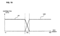
- FIG. 19 is the diagram that shows the feathering process.
- the feathering means a process to add a gradation of contribution ratio to the overlapping area of both volume images.
- the contribution ratio is the ratio of occupation in displaying that area, and less contribution ratio means more transparency.
- the contribution ratio is reduced as closer to the edge of the image.
- the volume images that are reconstructed separately will look more natural by the feathering process, enabling to see it as an integrated image visually.
- the combining unit 14 reads the weighting function reconstructing the contribution ratio shown in FIG. 19 from the external storage unit 1 c , and using this weighting function, while weighting each volume data that constructs the volume image, adds both volume images per view number.
- This weighting function is the function that remains the same until the vicinity of the volume image boundary, and whose contribution ratio is decreased as approaching from the vicinity of the volume image boundary to the boundary.
- FIG. 20 is a flow chart that shows the operation of the image reconstruction process operation.
- the image reconstruction processing apparatus obtains the projection data PD and biological signal data TD and stores them in the storage area (S 71 ). If the image reconstruction processing apparatus is included in X-ray CT apparatus that is described later, the projection data PD obtained by scanning the subject to be examined and the biological signal data TD obtained during the scan are stored. If the image reconstruction processing apparatus is consisted of other computer than X-ray CT apparatus, it is obtained via a network or a portable memory device.
- image reconstruction processing apparatus after the command is input by the image reconstruction process using the input unit 123 , displays the setting screen on the monitor 124 (S 72 ).
- the setting screen displays the pattern diagram of the subject to be examined SG.
- the reconstruction area SE reconstructed in synchronization with the biological signal with reference to the pattern diagram SG of the subject to be examined and the reconstruction area NSE reconstructed in asynchronization with the biological signal are indicated.
- the image reconstruction processing apparatus stores the view number Vx that shows the reconstruction area SE in synchronization with the indicated biological signal and the view number Vx that shows the reconstruction area NSE reconstructed in asynchronization with the biological signal in a partly overlapped way in the memory (S 73 ).
- the image reconstruction processing apparatus is included in X-ray CT apparatus, data indicating the reconstruction area NSE reconstructed in asynchronization with the biological signal and the reconstruction area SE reconstructed in synchronization with the indicated biological signal is stored in advance, at the steps of S 72 to S 73 , and then the projection data PD and biological signal data TD at the S 01 is stored sequentially during the scan.
- image reconstruction processing apparatus When projection data PD and biological signal data TD, as well as the data for the reconstruction area SE reconstructed in synchronization with the biological signal and the reconstruction area NSE in asynchronization with the biological signal are stored, image reconstruction processing apparatus performs the reconstruction process of the volume image.
- image reconstruction processing apparatus reads a view number Vx of the reconstruction area SE that is reconstructed in synchronization with the biological signal (S 74 ).
- the partial data PDa of the projection data PD to which this view number Vx is attached is read (S 75 ).
- the partial data TDa of biological signal data TD that is stored as a pair with the partial data PDa is read (S 76 ).
- the image reconstruction processing apparatus searches the partial data TDa that shows a particular phase among this partial data TDa (S 77 ).
- This search in order to search the phase of the physical movement at the noncontractile period for example, if the biological signal data TD is the electrocardiographic data, it searches the partial data TDa which a specified number of seconds have passed from Q wave.
- the partial data PDa of the projection data PD that is paired with this partial data TDa is further extracted from the read partial data PDa and gathered (S 78 ).
- the image reconstruction processing apparatus reconstructs the volume image from this extracted partial data PDa (S 79 ).
- the reconstructed volume image is kept temporally.
- the image reconstruction processing apparatus reads view number Vx of the reconstruction area NSE that is reconstructed in asynchronization with the biological signal (S 80 ).
- view number Vx of the reconstruction area NSE is read
- partial data PDa of the projection data PD in which this view number Vx is supplied (S 81 ).
- the image reconstruction processing apparatus reconstructs, from this partial data PDa, the volume image (S 82 ). The reconstructed volume image is temporarily kept.
- processing order may be changeable, as for reconstruction of the volume image of the reconstruction area SE reconstructed in synchronization of the biological signal of S 75 to S 79 , and as for that of the volume image of the reconstruction area NSE reconstructed in asynchronization with the biological signal of S 80 to S 82 .
- the image reconstruction processing apparatus performs the feathering process to each overlapping area of volume images (S 83 ), and superimposes such overlapped area to combine the volume image (S 84 ).
- the image reconstruction processing apparatus displays the combined volume image entirely on the monitor 124 (S 85 ).
- this feathering process can be performed prior to obtaining the projection data PD, which means it can be performed to pure raw data in advance.
- the projection data PD obtained during a single scan is segmented into the reconstruction area SE reconstructed in synchronization with the biological signal and the reconstruction area NSE reconstructed in asynchronization with the biological signal, and then a volume image is formed by a separate method for reconstructing the image.
- change of the moving speed of the bed board 112 b may be accompanied with the change of the number of lines of X-ray detecting elements provided by the detector 111 c . Also, even when the bed board 112 b is being accelerated, emission of X-rays is continued, and the image is reconstructed from the projection data PD of the emission area.
- the scan-controlling unit 122 outputs the driving signal of current value that corresponds to the moving speed set for the reconstruction area NSE onto the bed-driving unit 112 c .
- segmentation of the reconstruction area SE reconstructed in synchronization with the biological signal and reconstruction area NSE reconstructed in asynchronization with the biological signal may be performed to the transmission data only, and it can be segmented at the time of projection data or pure raw data.
Abstract
Description
Views(Z 1)≧BPview (Equation 1)
Views(Z 1)={DW/2−(|Z 0 −Z 1|)}/tan θ (Equation 2)
tan θ=f(HP) (Equation 3)
f(HP)≦{DW/2−(|Z 0 −Z 1|)}/BPview (Equation 4)
Views(Z 1)={DW/2−(|Z 0 −Z 1|)}/tan θ+Cviews(Z 1) (
tan θ=f(HP org) (Equation 3′)
Cviews(Z 1)≧BPview−{DW/2−(|Z 0 −Z 1|)}/tan f(HP org) (Equation 4′)
Claims (17)
Applications Claiming Priority (2)
| Application Number | Priority Date | Filing Date | Title |
|---|---|---|---|
| JP2006-071057 | 2006-03-15 | ||
| JP2006071057 | 2006-03-15 |
Publications (2)
| Publication Number | Publication Date |
|---|---|
| US20070217567A1 US20070217567A1 (en) | 2007-09-20 |
| US7885374B2 true US7885374B2 (en) | 2011-02-08 |
Family
ID=38198392
Family Applications (1)
| Application Number | Title | Priority Date | Filing Date |
|---|---|---|---|
| US11/685,985 Active 2028-08-06 US7885374B2 (en) | 2006-03-15 | 2007-03-14 | X-ray CT apparatus, a method for changing the helical pitch, an image reconstruction processing apparatus, an image reconstruction processing method, and an image reconstruction processing program |
Country Status (3)
| Country | Link |
|---|---|
| US (1) | US7885374B2 (en) |
| EP (1) | EP1834585B1 (en) |
| JP (2) | JP5439537B2 (en) |
Cited By (2)
| Publication number | Priority date | Publication date | Assignee | Title |
|---|---|---|---|---|
| US20110286574A1 (en) * | 2010-05-21 | 2011-11-24 | Tatsuro Suzuki | X-ray computed tomography apparatus |
| US20160073974A1 (en) * | 2013-05-28 | 2016-03-17 | Kabushiki Kaisha Toshiba | Medical image diagnosis apparatus and control method |
Families Citing this family (19)
| Publication number | Priority date | Publication date | Assignee | Title |
|---|---|---|---|---|
| ATE550990T1 (en) * | 2006-08-22 | 2012-04-15 | Koninkl Philips Electronics Nv | ARTIFACT CORRECTION FOR MOTION ARTIFACT IMAGES |
| US8355551B2 (en) * | 2009-02-27 | 2013-01-15 | General Electric Company | Method and apparatus for reducing image artifacts |
| US7933377B2 (en) * | 2009-06-03 | 2011-04-26 | General Electric Company | Method of CT perfusion imaging and apparatus for implementing same |
| JP5981129B2 (en) * | 2011-12-01 | 2016-08-31 | 東芝メディカルシステムズ株式会社 | X-ray computed tomography system |
| WO2014050931A1 (en) | 2012-09-26 | 2014-04-03 | 株式会社ニコン | X-ray device and structure manufacturing method |
| CN103330573B (en) * | 2013-06-28 | 2015-05-20 | 上海博恩登特科技有限公司 | Synchronizing impulse perspective oral cavity CT (Computed Tomography) and synchronizing method thereof |
| CN104939861B (en) * | 2015-06-25 | 2018-11-20 | 苏州海斯菲德信息科技有限公司 | Vivo CT scan control method based on segmentation speed regulation |
| US10049449B2 (en) * | 2015-09-21 | 2018-08-14 | Shanghai United Imaging Healthcare Co., Ltd. | System and method for image reconstruction |
| EP3389497B1 (en) * | 2015-12-17 | 2020-12-09 | Koninklijke Philips N.V. | Method and device for a medical image analysis |
| US10939879B2 (en) * | 2016-07-25 | 2021-03-09 | Canon Medical Systems Corporation | X-ray CT apparatus |
| CN106264587B (en) * | 2016-07-25 | 2020-05-19 | 东软医疗系统股份有限公司 | Multi-sequence scanning method and device |
| US10182771B2 (en) * | 2017-02-10 | 2019-01-22 | Siemens Healthcare Gmbh | Method and system for dose-optimized computed tomography scanning of a target organ |
| JP7005240B2 (en) | 2017-09-11 | 2022-01-21 | キヤノンメディカルシステムズ株式会社 | Medical diagnostic imaging equipment |
| CN111615364A (en) * | 2018-01-19 | 2020-09-01 | 皇家飞利浦有限公司 | Scan parameter adjustment during contrast enhanced scan |
| CN109009193A (en) * | 2018-07-13 | 2018-12-18 | 沈阳东软医疗系统有限公司 | Dose modulation, device and helical CT device |
| CN111768858A (en) * | 2020-06-30 | 2020-10-13 | 上海联影医疗科技有限公司 | Method, system and computer equipment for displaying scanning pitch parameters |
| US20220245867A1 (en) * | 2021-01-29 | 2022-08-04 | James R. Glidewell Dental Ceramics, Inc. | Simultaneous ct scanning and reconstruction |
| US11721017B2 (en) | 2021-03-31 | 2023-08-08 | James R. Glidewell Dental Ceramics, Inc. | CT reconstruction quality control |
| CN113362413B (en) * | 2021-06-03 | 2023-11-03 | 东软医疗系统股份有限公司 | CT image data acquisition method and device and computer equipment |
Citations (15)
| Publication number | Priority date | Publication date | Assignee | Title |
|---|---|---|---|---|
| US5390112A (en) * | 1993-10-04 | 1995-02-14 | General Electric Company | Three-dimensional computerized tomography scanning method and system for imaging large objects with smaller area detectors |
| US6256366B1 (en) * | 1999-07-22 | 2001-07-03 | Analogic Corporation | Apparatus and method for reconstruction of volumetric images in a computed tomography system using sementation of slices |
| US6353653B1 (en) * | 1999-11-23 | 2002-03-05 | General Electric Company | Method and apparatus for reducing artifacts in images reconstructed from image data acquired by a computed tomography system |
| US6421411B1 (en) | 2001-05-10 | 2002-07-16 | Ge Medical Systems Global Technology Company, Llc | Methods and apparatus for helical image artifact reduction |
| US20030163039A1 (en) * | 2002-02-28 | 2003-08-28 | Tin-Su Pan | System and method of imaging using a variable speed for thorax imaging |
| US6721386B2 (en) * | 2002-03-15 | 2004-04-13 | Ge Medical Systems Global Technology Co., Llc | Method and apparatus of cardiac CT imaging using ECG and mechanical motion signals |
| JP2004208715A (en) * | 2002-12-26 | 2004-07-29 | Ge Medical Systems Global Technology Co Llc | X-ray ct system, its operation console, and its control method |
| WO2004100791A1 (en) * | 2003-05-16 | 2004-11-25 | Siemens Aktiengesellschaft | Production of ct images by spiral reconstruction of an object for examination moving in a partially cyclical manner |
| JP2005066042A (en) | 2003-08-25 | 2005-03-17 | Toshiba Corp | X-ray computer tomography apparatus |
| US20050074091A1 (en) | 2003-10-03 | 2005-04-07 | Osamu Tsujii | Radiation image-acquiring apparatus, and radiation image-acquiring method |
| US20050158740A1 (en) * | 2003-11-06 | 2005-07-21 | Ronen Shemesh | Variants of human glycoprotein hormone alpha chain: compositions and uses thereof |
| US20050175140A1 (en) * | 2004-02-05 | 2005-08-11 | Canon Kabushiki Kaisha | X-ray image processing apparatus and x-ray image processing method |
| US20060034419A1 (en) * | 2004-08-13 | 2006-02-16 | Ge Medical Systems Global Technology Company, Llc | Scan control method and X-ray CT apparatus |
| EP1712181A2 (en) | 2005-04-15 | 2006-10-18 | Kabushiki Kaisha Toshiba | X-ray computer tomography apparatus with pre-scan to optimise timing of main scan following administration of a contrast medium |
| US20060262896A1 (en) | 2005-05-19 | 2006-11-23 | Ge Medical Systems Global Technology Company, Llc | Scan parameter setting method for shuttle mode helical scan and X-ray CT apparatus |
Family Cites Families (3)
| Publication number | Priority date | Publication date | Assignee | Title |
|---|---|---|---|---|
| JP3748300B2 (en) * | 1996-10-31 | 2006-02-22 | 株式会社東芝 | X-ray computed tomography system |
| JP2002095655A (en) * | 2000-09-26 | 2002-04-02 | Shimadzu Corp | Ct apparatus |
| JP4339202B2 (en) * | 2004-07-30 | 2009-10-07 | ジーイー・メディカル・システムズ・グローバル・テクノロジー・カンパニー・エルエルシー | X-ray CT system |
-
2007
- 2007-03-14 EP EP07005283.2A patent/EP1834585B1/en active Active
- 2007-03-14 US US11/685,985 patent/US7885374B2/en active Active
-
2012
- 2012-05-28 JP JP2012120761A patent/JP5439537B2/en active Active
-
2013
- 2013-06-03 JP JP2013117338A patent/JP2013198747A/en active Pending
Patent Citations (18)
| Publication number | Priority date | Publication date | Assignee | Title |
|---|---|---|---|---|
| US5390112A (en) * | 1993-10-04 | 1995-02-14 | General Electric Company | Three-dimensional computerized tomography scanning method and system for imaging large objects with smaller area detectors |
| US6256366B1 (en) * | 1999-07-22 | 2001-07-03 | Analogic Corporation | Apparatus and method for reconstruction of volumetric images in a computed tomography system using sementation of slices |
| US6353653B1 (en) * | 1999-11-23 | 2002-03-05 | General Electric Company | Method and apparatus for reducing artifacts in images reconstructed from image data acquired by a computed tomography system |
| US6421411B1 (en) | 2001-05-10 | 2002-07-16 | Ge Medical Systems Global Technology Company, Llc | Methods and apparatus for helical image artifact reduction |
| US20030163039A1 (en) * | 2002-02-28 | 2003-08-28 | Tin-Su Pan | System and method of imaging using a variable speed for thorax imaging |
| JP2003275200A (en) | 2002-02-28 | 2003-09-30 | Ge Medical Systems Global Technology Co Llc | System and method of imaging using variable speed table for thorax imaging |
| US6721386B2 (en) * | 2002-03-15 | 2004-04-13 | Ge Medical Systems Global Technology Co., Llc | Method and apparatus of cardiac CT imaging using ECG and mechanical motion signals |
| JP2004208715A (en) * | 2002-12-26 | 2004-07-29 | Ge Medical Systems Global Technology Co Llc | X-ray ct system, its operation console, and its control method |
| WO2004100791A1 (en) * | 2003-05-16 | 2004-11-25 | Siemens Aktiengesellschaft | Production of ct images by spiral reconstruction of an object for examination moving in a partially cyclical manner |
| US20070092057A1 (en) * | 2003-05-16 | 2007-04-26 | Herbert Bruder | Production of ct images by spiral reconstruction of an examination object moving in a partially cyclical manner |
| JP2005066042A (en) | 2003-08-25 | 2005-03-17 | Toshiba Corp | X-ray computer tomography apparatus |
| US20050089133A1 (en) | 2003-08-25 | 2005-04-28 | Masaharu Tsuyuki | X-ray computed tomography apparatus |
| US20050074091A1 (en) | 2003-10-03 | 2005-04-07 | Osamu Tsujii | Radiation image-acquiring apparatus, and radiation image-acquiring method |
| US20050158740A1 (en) * | 2003-11-06 | 2005-07-21 | Ronen Shemesh | Variants of human glycoprotein hormone alpha chain: compositions and uses thereof |
| US20050175140A1 (en) * | 2004-02-05 | 2005-08-11 | Canon Kabushiki Kaisha | X-ray image processing apparatus and x-ray image processing method |
| US20060034419A1 (en) * | 2004-08-13 | 2006-02-16 | Ge Medical Systems Global Technology Company, Llc | Scan control method and X-ray CT apparatus |
| EP1712181A2 (en) | 2005-04-15 | 2006-10-18 | Kabushiki Kaisha Toshiba | X-ray computer tomography apparatus with pre-scan to optimise timing of main scan following administration of a contrast medium |
| US20060262896A1 (en) | 2005-05-19 | 2006-11-23 | Ge Medical Systems Global Technology Company, Llc | Scan parameter setting method for shuttle mode helical scan and X-ray CT apparatus |
Non-Patent Citations (2)
| Title |
|---|
| Hsieh, Computed Tomography: Principles, Designs, Artifacts and Recent Advances, 2003, SPIE Press, ISBN 0-8194-4425-1, pp. 288-292. * |
| PTO 09-8184, Oct. 2009, English translation for JP 2004208715 A. * |
Cited By (4)
| Publication number | Priority date | Publication date | Assignee | Title |
|---|---|---|---|---|
| US20110286574A1 (en) * | 2010-05-21 | 2011-11-24 | Tatsuro Suzuki | X-ray computed tomography apparatus |
| US8693620B2 (en) * | 2010-05-21 | 2014-04-08 | Kabushiki Kaisha Toshiba | X-ray computed tomography apparatus |
| US20160073974A1 (en) * | 2013-05-28 | 2016-03-17 | Kabushiki Kaisha Toshiba | Medical image diagnosis apparatus and control method |
| US10709408B2 (en) * | 2013-05-28 | 2020-07-14 | Canon Medical Systems Corporation | Medical image diagnosis apparatus and control method |
Also Published As
| Publication number | Publication date |
|---|---|
| EP1834585B1 (en) | 2015-09-23 |
| JP2013198747A (en) | 2013-10-03 |
| JP2012183340A (en) | 2012-09-27 |
| US20070217567A1 (en) | 2007-09-20 |
| EP1834585A3 (en) | 2007-10-17 |
| JP5439537B2 (en) | 2014-03-12 |
| EP1834585A2 (en) | 2007-09-19 |
Similar Documents
| Publication | Publication Date | Title |
|---|---|---|
| US7885374B2 (en) | X-ray CT apparatus, a method for changing the helical pitch, an image reconstruction processing apparatus, an image reconstruction processing method, and an image reconstruction processing program | |
| JP4771944B2 (en) | Radiation tomographic imaging system | |
| US6370217B1 (en) | Volumetric computed tomography system for cardiac imaging | |
| US7715520B2 (en) | X-ray computed tomography apparatus | |
| US8379792B2 (en) | X-ray CT apparatus | |
| JP4945203B2 (en) | X-ray computed tomography system | |
| JP4393086B2 (en) | X-ray computed tomography system | |
| JP5165903B2 (en) | X-ray CT apparatus, helical pitch changing method | |
| JP6233980B2 (en) | X-ray CT apparatus and image reconstruction method | |
| JP2001190547A (en) | Method for inspecting body scope of periodic movement | |
| JP2007175258A (en) | Tomographic x-ray equipment and x-ray tomographic method | |
| WO2015194545A1 (en) | X-ray ct device and image reconfiguration method | |
| JP3950849B2 (en) | High-pitch cardiac helical scan using extended reconstruction window | |
| US11006917B2 (en) | Medical-information processing apparatus and X-ray CT apparatus | |
| US10299750B2 (en) | Medical image processing apparatus and X-ray CT apparatus | |
| US20110164800A1 (en) | X-ray ct apparatus | |
| JP2002191594A (en) | X-ray computed tomography photographing system | |
| JP4007928B2 (en) | X-ray CT system | |
| JP4448654B2 (en) | X-ray CT system, operation console thereof, and control method thereof | |
| WO2013187461A1 (en) | X-ray ct apparatus and image reconstruction method | |
| JP2002191595A (en) | X-ray computed tomography photographing system | |
| Flohr et al. | Cardiac gating | |
| Flohr et al. | Cardiac Gating 2 |
Legal Events
| Date | Code | Title | Description |
|---|---|---|---|
| AS | Assignment |
Owner name: KABUSHIKI KAISHA TOSHIBA, JAPAN Free format text: ASSIGNMENT OF ASSIGNORS INTEREST;ASSIGNORS:NOSHI, YASUHIRO;MAEDA, TATSUO;OKUMURA, MIWA;AND OTHERS;SIGNING DATES FROM 20070201 TO 20070219;REEL/FRAME:019010/0437 Owner name: TOSHIBA MEDICAL SYSTEMS CORPORATION, JAPAN Free format text: ASSIGNMENT OF ASSIGNORS INTEREST;ASSIGNORS:NOSHI, YASUHIRO;MAEDA, TATSUO;OKUMURA, MIWA;AND OTHERS;SIGNING DATES FROM 20070201 TO 20070219;REEL/FRAME:019010/0437 Owner name: TOSHIBA MEDICAL SYSTEMS CORPORATION, JAPAN Free format text: ASSIGNMENT OF ASSIGNORS INTEREST;ASSIGNORS:NOSHI, YASUHIRO;MAEDA, TATSUO;OKUMURA, MIWA;AND OTHERS;REEL/FRAME:019010/0437;SIGNING DATES FROM 20070201 TO 20070219 Owner name: KABUSHIKI KAISHA TOSHIBA, JAPAN Free format text: ASSIGNMENT OF ASSIGNORS INTEREST;ASSIGNORS:NOSHI, YASUHIRO;MAEDA, TATSUO;OKUMURA, MIWA;AND OTHERS;REEL/FRAME:019010/0437;SIGNING DATES FROM 20070201 TO 20070219 |
|
| STCF | Information on status: patent grant |
Free format text: PATENTED CASE |
|
| FEPP | Fee payment procedure |
Free format text: PAYOR NUMBER ASSIGNED (ORIGINAL EVENT CODE: ASPN); ENTITY STATUS OF PATENT OWNER: LARGE ENTITY |
|
| FPAY | Fee payment |
Year of fee payment: 4 |
|
| AS | Assignment |
Owner name: TOSHIBA MEDICAL SYSTEMS CORPORATION, JAPAN Free format text: ASSIGNMENT OF ASSIGNORS INTEREST;ASSIGNOR:KABUSHIKI KAISHA TOSHIBA;REEL/FRAME:038891/0693 Effective date: 20160316 |
|
| MAFP | Maintenance fee payment |
Free format text: PAYMENT OF MAINTENANCE FEE, 8TH YEAR, LARGE ENTITY (ORIGINAL EVENT CODE: M1552) Year of fee payment: 8 |
|
| MAFP | Maintenance fee payment |
Free format text: PAYMENT OF MAINTENANCE FEE, 12TH YEAR, LARGE ENTITY (ORIGINAL EVENT CODE: M1553); ENTITY STATUS OF PATENT OWNER: LARGE ENTITY Year of fee payment: 12 |