JP6128751B2 - Image forming apparatus - Google Patents

Image forming apparatus Download PDF

Info

Publication number
JP6128751B2
JP6128751B2 JP2012109929A JP2012109929A JP6128751B2 JP 6128751 B2 JP6128751 B2 JP 6128751B2 JP 2012109929 A JP2012109929 A JP 2012109929A JP 2012109929 A JP2012109929 A JP 2012109929A JP 6128751 B2 JP6128751 B2 JP 6128751B2
Authority
JP
Japan
Prior art keywords
light
amount
detection
light emission
received
Prior art date
Legal status (The legal status is an assumption and is not a legal conclusion. Google has not performed a legal analysis and makes no representation as to the accuracy of the status listed.)
Active
Application number
JP2012109929A
Other languages
Japanese (ja)
Other versions
JP2013238669A5 (en
JP2013238669A (en
Inventor
武士 榛葉
武士 榛葉
中川 健
健 中川
慎理 渡辺
慎理 渡辺
Current Assignee (The listed assignees may be inaccurate. Google has not performed a legal analysis and makes no representation or warranty as to the accuracy of the list.)
Canon Inc
Original Assignee
Canon Inc
Priority date (The priority date is an assumption and is not a legal conclusion. Google has not performed a legal analysis and makes no representation as to the accuracy of the date listed.)
Filing date
Publication date
Application filed by Canon Inc filed Critical Canon Inc
Priority to JP2012109929A priority Critical patent/JP6128751B2/en
Priority to US13/868,555 priority patent/US9594337B2/en
Priority to EP13165035.0A priority patent/EP2682818B1/en
Priority to CN201310170639.XA priority patent/CN103389635B/en
Priority to KR1020130052963A priority patent/KR101676080B1/en
Publication of JP2013238669A publication Critical patent/JP2013238669A/en
Publication of JP2013238669A5 publication Critical patent/JP2013238669A5/ja
Application granted granted Critical
Publication of JP6128751B2 publication Critical patent/JP6128751B2/en
Active legal-status Critical Current
Anticipated expiration legal-status Critical

Links

Images

Classifications

    • GPHYSICS
    • G03PHOTOGRAPHY; CINEMATOGRAPHY; ANALOGOUS TECHNIQUES USING WAVES OTHER THAN OPTICAL WAVES; ELECTROGRAPHY; HOLOGRAPHY
    • G03GELECTROGRAPHY; ELECTROPHOTOGRAPHY; MAGNETOGRAPHY
    • G03G15/00Apparatus for electrographic processes using a charge pattern
    • G03G15/55Self-diagnostics; Malfunction or lifetime display
    • GPHYSICS
    • G03PHOTOGRAPHY; CINEMATOGRAPHY; ANALOGOUS TECHNIQUES USING WAVES OTHER THAN OPTICAL WAVES; ELECTROGRAPHY; HOLOGRAPHY
    • G03GELECTROGRAPHY; ELECTROPHOTOGRAPHY; MAGNETOGRAPHY
    • G03G15/00Apparatus for electrographic processes using a charge pattern
    • G03G15/01Apparatus for electrographic processes using a charge pattern for producing multicoloured copies
    • G03G15/0142Structure of complete machines
    • G03G15/0178Structure of complete machines using more than one reusable electrographic recording member, e.g. one for every monocolour image
    • G03G15/0189Structure of complete machines using more than one reusable electrographic recording member, e.g. one for every monocolour image primary transfer to an intermediate transfer belt
    • GPHYSICS
    • G03PHOTOGRAPHY; CINEMATOGRAPHY; ANALOGOUS TECHNIQUES USING WAVES OTHER THAN OPTICAL WAVES; ELECTROGRAPHY; HOLOGRAPHY
    • G03GELECTROGRAPHY; ELECTROPHOTOGRAPHY; MAGNETOGRAPHY
    • G03G15/00Apparatus for electrographic processes using a charge pattern
    • G03G15/50Machine control of apparatus for electrographic processes using a charge pattern, e.g. regulating differents parts of the machine, multimode copiers, microprocessor control
    • G03G15/5054Machine control of apparatus for electrographic processes using a charge pattern, e.g. regulating differents parts of the machine, multimode copiers, microprocessor control by measuring the characteristics of an intermediate image carrying member or the characteristics of an image on an intermediate image carrying member, e.g. intermediate transfer belt or drum, conveyor belt
    • G03G15/5058Machine control of apparatus for electrographic processes using a charge pattern, e.g. regulating differents parts of the machine, multimode copiers, microprocessor control by measuring the characteristics of an intermediate image carrying member or the characteristics of an image on an intermediate image carrying member, e.g. intermediate transfer belt or drum, conveyor belt using a test patch
    • GPHYSICS
    • G03PHOTOGRAPHY; CINEMATOGRAPHY; ANALOGOUS TECHNIQUES USING WAVES OTHER THAN OPTICAL WAVES; ELECTROGRAPHY; HOLOGRAPHY
    • G03GELECTROGRAPHY; ELECTROPHOTOGRAPHY; MAGNETOGRAPHY
    • G03G2215/00Apparatus for electrophotographic processes
    • G03G2215/00025Machine control, e.g. regulating different parts of the machine
    • G03G2215/00029Image density detection
    • G03G2215/00033Image density detection on recording member
    • G03G2215/00037Toner image detection
    • G03G2215/00042Optical detection
    • GPHYSICS
    • G03PHOTOGRAPHY; CINEMATOGRAPHY; ANALOGOUS TECHNIQUES USING WAVES OTHER THAN OPTICAL WAVES; ELECTROGRAPHY; HOLOGRAPHY
    • G03GELECTROGRAPHY; ELECTROPHOTOGRAPHY; MAGNETOGRAPHY
    • G03G2215/00Apparatus for electrophotographic processes
    • G03G2215/01Apparatus for electrophotographic processes for producing multicoloured copies
    • G03G2215/0151Apparatus for electrophotographic processes for producing multicoloured copies characterised by the technical problem
    • G03G2215/0158Colour registration
    • G03G2215/0161Generation of registration marks
    • GPHYSICS
    • G03PHOTOGRAPHY; CINEMATOGRAPHY; ANALOGOUS TECHNIQUES USING WAVES OTHER THAN OPTICAL WAVES; ELECTROGRAPHY; HOLOGRAPHY
    • G03GELECTROGRAPHY; ELECTROPHOTOGRAPHY; MAGNETOGRAPHY
    • G03G2215/00Apparatus for electrophotographic processes
    • G03G2215/01Apparatus for electrophotographic processes for producing multicoloured copies
    • G03G2215/0151Apparatus for electrophotographic processes for producing multicoloured copies characterised by the technical problem
    • G03G2215/0164Uniformity control of the toner density at separate colour transfers

Description

本発明は、主に電子写真方式、静電記憶方式の複写機、プリンタなどの画像形成装置に関する。特に、画像形成装置における濃度及び位置ずれの制御方法に関する。   The present invention mainly relates to image forming apparatuses such as electrophotographic and electrostatic storage type copying machines and printers. In particular, the present invention relates to a method for controlling density and positional deviation in an image forming apparatus.

複数の感光体を備えた画像形成装置は、感光体の機械的取り付けの誤差や、各色のレーザ光の光路長の誤差や、光路長の変化等により、各色間での相対的な位置ずれが発生する。また、使用環境やプリント枚数などの諸条件によって各色の画像濃度が変動し、カラーバランスが変動する。   An image forming apparatus having a plurality of photoconductors has a relative positional shift between colors due to an error in mechanical attachment of the photoconductors, an error in the optical path length of laser light of each color, or a change in optical path length. Occur. Further, the image density of each color varies depending on various conditions such as the use environment and the number of prints, and the color balance varies.

このため、特許文献1及び2は、中間転写ベルトに位置ずれと、濃度を検出するためのトナー像である検出パターンをそれぞれ形成し、位置ずれ及び濃度の補正を行う構成を開示している。特許文献1及び2では、位置ずれ及び濃度の検出パターンを同一の検出部で検出することで、装置の大型化及びコスト上昇を回避している。   For this reason, Patent Documents 1 and 2 disclose a configuration in which a detection pattern that is a toner image for detecting a positional deviation and a density is formed on the intermediate transfer belt, respectively, and the positional deviation and the density are corrected. In Patent Documents 1 and 2, the detection of misalignment and density is detected by the same detection unit, thereby avoiding an increase in size and cost of the apparatus.

特許文献3は、位置ずれ及び濃度の補正を連続して行う必要がある場合、中間転写ベルトに位置ずれと、濃度の検出パターンの両方を形成して検出することで、補正制御処理の短縮を行うことを開示している。   In Patent Document 3, when it is necessary to continuously perform misregistration and density correction, the correction control process can be shortened by forming and detecting both the misregistration and the density detection pattern on the intermediate transfer belt. Discloses what to do.

特開平01-167769号公報Japanese Patent Laid-Open No. 01-167769 特開平11-143171号公報JP-A-11-143171 特開2001−166553号公報JP 2001-166553 A

濃度検出のためのセンサは、中間転写ベルトや発光素子の劣化が生じても濃度検出を可能とする様に制御されている。これに対して位置ずれの検出は、検出パターン内のトナー濃度や、検出パターンと中間転写ベルト表面との濃度差を利用しているため、例えば、濃度差が小さい場合には、位置ずれを検出できない場合が生じる。位置ずれを検出できない場合には、濃度の検出結果からプロセス条件、例えば、レーザ光量、帯電バイアス、現像バイアス等を変更して、再度、位置ずれの検出を開始することになるが補正制御の時間が長くなってしまう。   The sensor for detecting the density is controlled so that the density can be detected even if the intermediate transfer belt or the light emitting element is deteriorated. On the other hand, since the position deviation is detected using the toner density in the detection pattern or the density difference between the detection pattern and the intermediate transfer belt surface, for example, when the density difference is small, the position deviation is detected. There are cases where it cannot be done. If the position deviation cannot be detected, the process conditions such as the laser light quantity, the charging bias, the developing bias, etc. are changed from the density detection result, and the detection of the position deviation is started again. Will become longer.

本発明は、同じ設定で位置ずれと濃度の両方の検出パターンを検出できる画像形成装置を提供するものである。   The present invention provides an image forming apparatus capable of detecting both misregistration and density detection patterns with the same settings.

本発明の画像形成装置は、像担持体に各色のトナー像を形成する画像形成手段と、記像担持体に形成されたトナー像に光を照射して、その反射光を受光する検出手段と、前記像担持体に形成したトナー像である第1の検出パターンを前記検出手段が検出しているときの前記検出手段の受光量を閾値により判定することで、前記像担持体に形成される前記各色のトナー像の相対的な位置ずれ量を検出し、前記像担持体に形成したトナー像である第2の検出パターンを前記検出手段で検出することで、前記像担持体に形成される前記各色のトナー像の濃度を検出する制御を行う制御手段と、を備えており、前記第1の検出パターンは、ブラックのトナー像の部分であるブラック部分と、その他の色の部分であるカラー部分とを含み、前記位置ずれ量の検出と前記濃度の検出を連続して行う場合、前記画像形成手段は、前記第1の検出パターン及び前記第2の検出パターンの両方を前記像担持体に形成し、記制御手段は、前記第1の検出パターンの検出結果に基づき、前記検出手段が受光する前記ブラック部分からの拡散反射光の受光量が前記閾値未満であり、前記検出手段が受光する前記カラー部分からの拡散反射光の受光量が前記閾値より大きくなる様に、前記第1の検出パターン及び前記第2の検出パターンを検出するために用いられる前記検出手段の発光量、前記閾値、又は、前記検出手段の感度を設定し、かつ、前記第1の検出パターンの検出結果に基づき、前記カラー部分からの拡散反射光の受光量が前記検出手段で受光できる拡散反射光の受光量の上限値未満となる様に、前記第1の検出パターン及び前記第2の検出パターンを検出するために用いられる前記検出手段の発光量、又は、前記検出手段の感度を設定することを特徴とする。
The image forming apparatus of the present invention, by irradiating the image bearing member and image forming means for forming a toner image of each color, the light before the toner image formed on Kizo carrier, detecting means for receiving reflected light And determining the amount of light received by the detection means when the detection means detects the first detection pattern, which is a toner image formed on the image carrier, based on a threshold value. And detecting a second detection pattern, which is a toner image formed on the image carrier, by the detection means. Control means for performing control to detect the density of each color toner image, and the first detection pattern is a black portion that is a portion of a black toner image and a portion of another color. Including the color portion, If the detection of detection and the concentration of the amount in succession, said image forming means, both of said first detection pattern and second detection pattern is formed on the image bearing member, before Symbol control means Based on the detection result of the first detection pattern, the amount of diffuse reflection light received from the black portion received by the detection means is less than the threshold value, and the diffuse reflection from the color portion received by the detection means. The light emission amount of the detection means, the threshold value, or the sensitivity of the detection means used for detecting the first detection pattern and the second detection pattern so that the amount of received light is larger than the threshold value. set, and, based on the detection result of the first detection pattern, the like received light amount of the diffuse reflection light from the collar portion is less than the upper limit value of the received light amount of the diffuse reflection light can be received by the detection means , Light emission amount of the detection means used for detecting the first detection pattern and second detection pattern, or, and sets the sensitivity of said detection means.

本発明の画像形成装置は、像担持体に各色のトナー像を形成する画像形成手段と、記像担持体に形成されたトナー像に光を照射して、その反射光を受光する検出手段と、前記像担持体に形成したトナー像である第1の検出パターンを前記検出手段が検出しているときの前記検出手段の受光量を閾値により判定することで、前記像担持体に形成される前記各色のトナー像の相対的な位置ずれ量を検出し、前記像担持体に形成したトナー像である第2の検出パターンを前記検出手段で検出することで、前記像担持体に形成される前記各色のトナー像の濃度を検出する制御を行う制御手段と、を備えており、前記位置ずれ量の検出と前記濃度の検出を連続して行う場合、前記画像形成手段は、前記第1の検出パターン及び前記第2の検出パターンの両方を前記像担持体に形成し、記制御手段は、前記第1の検出パターンの検出結果に基づき、前記検出手段が受光する前記第1の検出パターンからの正反射光の受光量が前記閾値未満であり、前記検出手段が受光する前記像担持体の表面からの正反射光の受光量が前記閾値より大きくなる様に、前記第1の検出パターン及び前記第2の検出パターンを検出するために用いられる前記検出手段の発光量、前記閾値、又は、前記検出手段の感度を設定し、かつ、前記第1の検出パターンの検出結果に基づき、前記像担持体の表面からの正反射光の受光量が前記検出手段で受光できる正反射光の受光量の上限値未満となる様に、前記第1の検出パターン及び前記第2の検出パターンを検出するために用いられる前記検出手段の発光量、又は、前記検出手段の感度を設定することを特徴とする。

The image forming apparatus of the present invention, by irradiating the image bearing member and image forming means for forming a toner image of each color, the light before the toner image formed on Kizo carrier, detecting means for receiving reflected light And determining the amount of light received by the detection means when the detection means detects the first detection pattern, which is a toner image formed on the image carrier, based on a threshold value. And detecting a second detection pattern, which is a toner image formed on the image carrier, by the detection means. Control means for performing control to detect the density of the toner image of each color, and when the detection of the positional deviation amount and the detection of the density are successively performed, Detection pattern and the second detection pattern Both were formed on the image bearing member, before Symbol control means based on the detection result of the first detection pattern, the received light amount of regular reflection light from the first detection pattern, wherein the detection means for receiving said The first detection pattern and the second detection pattern are detected so that the amount of specularly reflected light from the surface of the image carrier received by the detection means is greater than the threshold, which is less than the threshold. The amount of light emitted from the detection means, the threshold value, or the sensitivity of the detection means used for the purpose is set, and the specularly reflected light from the surface of the image carrier is based on the detection result of the first detection pattern. Of the detection means used for detecting the first detection pattern and the second detection pattern so that the amount of received light is less than the upper limit of the amount of regular reflection light that can be received by the detection means. Quantity or before And setting the sensitivity of the detection means.

画像形成装置は、同じ設定で位置ずれと濃度の両方の検出パターンを検出することが可能になる。   The image forming apparatus can detect both misregistration and density detection patterns with the same setting.

一実施形態による画像形成装置の画像形成部の構成図。1 is a configuration diagram of an image forming unit of an image forming apparatus according to an embodiment. 一実施形態によるセンサ部の構成図。The block diagram of the sensor part by one Embodiment. 一実施形態による画像形成装置の構成図。1 is a configuration diagram of an image forming apparatus according to an embodiment. 一実施形態による検出パターンを示す図。The figure which shows the detection pattern by one Embodiment. 一実施形態による検出パターンと検出電圧との関係を示す図。The figure which shows the relationship between the detection pattern and detection voltage by one Embodiment. 一実施形態による発光素子の光量の決定の説明図。Explanatory drawing of determination of the light quantity of the light emitting element by one Embodiment. 一実施形態による発光素子の光量決定制御のフローチャート。The flowchart of the light quantity determination control of the light emitting element by one Embodiment. 一実施形態による検出パターンを示す図。The figure which shows the detection pattern by one Embodiment. 一実施形態による検出パターンと検出電圧との関係を示す図。The figure which shows the relationship between the detection pattern and detection voltage by one Embodiment. 一実施形態による発光素子の光量の決定の説明図。Explanatory drawing of determination of the light quantity of the light emitting element by one Embodiment. 一実施形態による発光素子の光量決定制御のフローチャート。The flowchart of the light quantity determination control of the light emitting element by one Embodiment. 一実施形態による発光素子の光量の決定の説明図。Explanatory drawing of determination of the light quantity of the light emitting element by one Embodiment. 一実施形態による発光素子の光量決定制御のフローチャート。The flowchart of the light quantity determination control of the light emitting element by one Embodiment. 一実施形態による受光素子を含むセンサ部の構成図。The block diagram of the sensor part containing the light receiving element by one Embodiment. 一実施形態による感度の決定の説明図。Explanatory drawing of the determination of the sensitivity by one Embodiment. 一実施形態によるセンサ部の感度決定制御のフローチャート。The flowchart of the sensitivity determination control of the sensor part by one Embodiment. 一実施形態による受光素子を含むセンサ部の構成図。The block diagram of the sensor part containing the light receiving element by one Embodiment. 一実施形態によるセンサ部の閾値及び感度決定制御のフローチャート。The flowchart of the threshold value of a sensor part and sensitivity determination control by one Embodiment.

(第一実施形態)図1は、本実施形態による画像形成装置の画像形成部の概略的な構成図である。なお、以下の各図において、実施形態の理解に必要ではない構成要素は簡略化のため省略する。なお、図1において、参照符号の最後のアルファベットがaの構成要素は、イエロー(Y)のトナー像を中間転写ベルト80に形成するものである。同様に、参照符号の最後のアルファベットがb、c、dの構成要素は、それぞれ、マゼンタ(M)、シアン(C)、ブラック(K)のトナー像を中間転写ベルト80に形成するものである。なお、各色のトナー像を中間転写ベルト80に形成する構成要素の動作は現像剤であるトナーの色以外は各色の構成要素で同様であるため、以下では、代表してイエローのトナー像を中間転写ベルト80に形成する構成要素について説明する。   (First Embodiment) FIG. 1 is a schematic configuration diagram of an image forming unit of an image forming apparatus according to the present embodiment. In the following drawings, components that are not necessary for understanding the embodiment are omitted for simplification. In FIG. 1, a component having a letter “a” at the end of a reference sign forms a yellow (Y) toner image on the intermediate transfer belt 80. Similarly, components whose reference numerals have the last alphabets b, c, and d form magenta (M), cyan (C), and black (K) toner images on the intermediate transfer belt 80, respectively. . The operation of the constituent elements for forming the toner images of the respective colors on the intermediate transfer belt 80 is the same for the constituent elements of the respective colors other than the toner color as the developer. The components formed on the transfer belt 80 will be described.

帯電ローラ2aは、像担持体である感光体1aと当接し感光体表面を均一に帯電する。露光部11aは、画像信号に基づいて変調されたレーザ光12aを感光体1a上に照射して感光体1aに静電潜像を形成する。現像ユニット8aは、イエローのトナーを有し、感光体1aに当接された現像ローラ4aにより感光体1aの静電潜像をトナーにより現像してトナー像を形成する。1次転写ローラ81aは、感光体1aに形成されたトナー像を像担持体である中間転写ベルト80に転写する。クリーニングユニット3aは、中間転写ベルト80に転写されず、感光体1aに残ったトナーをクリーニングする。なお、感光体1a、帯電ローラ2a、クリーニングユニット3a及び現像ユニット8aは、画像形成装置から着脱自在な一体型のプロセスカートリッジ9aとなっている。   The charging roller 2a is in contact with the photoreceptor 1a which is an image carrier, and uniformly charges the surface of the photoreceptor. The exposure unit 11a irradiates the photosensitive member 1a with a laser beam 12a modulated based on the image signal to form an electrostatic latent image on the photosensitive member 1a. The developing unit 8a has yellow toner, and develops the electrostatic latent image on the photoreceptor 1a with toner by the developing roller 4a that is in contact with the photoreceptor 1a to form a toner image. The primary transfer roller 81a transfers the toner image formed on the photoreceptor 1a to an intermediate transfer belt 80 that is an image carrier. The cleaning unit 3a cleans the toner that is not transferred to the intermediate transfer belt 80 but remains on the photoreceptor 1a. The photosensitive member 1a, the charging roller 2a, the cleaning unit 3a, and the developing unit 8a are an integrated process cartridge 9a that is detachable from the image forming apparatus.

中間転写ベルト80は、二次転写対向ローラ86、駆動ローラ14、テンションローラ15の3本のローラにより支持されており、適当なテンションが維持されるようになっている。駆動ローラ14を駆動させることにより中間転写ベルト80は感光体1a〜1dに対して順方向に略同速度で移動する。中間転写ベルト80に、各色のトナー像を重ね合わせて転写することでカラー画像が形成される。中間転写ベルト80に転写されたトナー像は、二次転写ローラ82により搬送経路87を搬送される記録材に転写される。記録材に転写されたトナー像は図示しない定着部により定着される。   The intermediate transfer belt 80 is supported by three rollers, that is, a secondary transfer counter roller 86, a driving roller 14, and a tension roller 15, so that an appropriate tension is maintained. By driving the drive roller 14, the intermediate transfer belt 80 moves in the forward direction at substantially the same speed with respect to the photoreceptors 1a to 1d. A color image is formed by superimposing and transferring the toner images of the respective colors onto the intermediate transfer belt 80. The toner image transferred to the intermediate transfer belt 80 is transferred to the recording material conveyed through the conveyance path 87 by the secondary transfer roller 82. The toner image transferred to the recording material is fixed by a fixing unit (not shown).

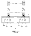
また、画像形成部には、図1に示す様に中間転写ベルト80と対向する位置に、位置ずれ及び濃度検出及び補正のためのセンサ部60が設けられている。図2は、本実施形態によるセンサ部60の構成図である。センサ部60は、中間転写ベルト80に向けて光を照射する発光素子203と、発光素子203が発光し、中間転写ベルト80の表面又はその表面に形成した検出パターンで反射した光を受光する受光素子204及び205を備えている。なお、受光素子204は、中間転写ベルト80の表面又は検出パターンで拡散反射した光を受光し、受光素子205は正反射した光を受光する様に設けられ、受光素子204及び205のそれぞれは受光量に応じた検出電圧を出力する。なお、中間転写ベルト80の各側に形成する検出パターンを検出する様に、発光素子203と、受光素子204及び205の組も、中間転写ベルト80の各側に設けられている。なお、図2は、位置ずれの検出パターン206と、濃度の検出パターン207が中間転写ベルト80に形成されている様子も示している。なお、本実施形態は、検出パターンを中間転写ベルトに形成してセンサ部60で検出するものであるが、検出パターンを形成するのは記録材を含む任意の像担持体とすることができる。   Further, the image forming unit is provided with a sensor unit 60 for detecting and correcting misalignment and density at a position facing the intermediate transfer belt 80 as shown in FIG. FIG. 2 is a configuration diagram of the sensor unit 60 according to the present embodiment. The sensor unit 60 emits light toward the intermediate transfer belt 80, and a light receiving element that receives the light emitted from the light emitting element 203 and reflected from the surface of the intermediate transfer belt 80 or a detection pattern formed on the surface. Elements 204 and 205 are provided. The light receiving element 204 receives light diffusely reflected by the surface of the intermediate transfer belt 80 or the detection pattern, and the light receiving element 205 is provided to receive regular reflected light. Each of the light receiving elements 204 and 205 receives light. The detection voltage corresponding to the amount is output. Note that a set of a light emitting element 203 and light receiving elements 204 and 205 is also provided on each side of the intermediate transfer belt 80 so as to detect a detection pattern formed on each side of the intermediate transfer belt 80. FIG. 2 also shows a state in which the misregistration detection pattern 206 and the density detection pattern 207 are formed on the intermediate transfer belt 80. In this embodiment, a detection pattern is formed on the intermediate transfer belt and detected by the sensor unit 60. However, the detection pattern can be formed by any image carrier including a recording material.

図3は、画像形成装置のシステム構成を説明するためのブロック図である。コントローラ301は、ホストコンピュータ300及びエンジン制御部302と相互に通信が可能となっている。コントローラ301は、位置ずれ及び濃度の補正制御を実行する場合は、補正制御開始コマンドを、エンジン制御部302に出力する。CPU311は、インタフェース部310経由で補正制御開始コマンドを受信すると、画像制御部313に補正制御開始を指示する。画像制御部313は、補正制御開始の指示を受け取ると、画像形成部を制御して、検出パターンを形成するための準備を行う。準備完了後、CPU311は、コントローラ301に、検出パターンに対応する画像信号の送信を要求する。コントローラ301は、CPU311からの要求に応じて画像信号をエンジン制御部302に出力する。   FIG. 3 is a block diagram for explaining the system configuration of the image forming apparatus. The controller 301 can communicate with the host computer 300 and the engine control unit 302. The controller 301 outputs a correction control start command to the engine control unit 302 when executing correction control of positional deviation and density. When receiving the correction control start command via the interface unit 310, the CPU 311 instructs the image control unit 313 to start correction control. Upon receiving an instruction to start correction control, the image control unit 313 controls the image forming unit to prepare for forming a detection pattern. After completing the preparation, the CPU 311 requests the controller 301 to transmit an image signal corresponding to the detection pattern. The controller 301 outputs an image signal to the engine control unit 302 in response to a request from the CPU 311.

画像処理GA312は、コントローラ301から画像信号を受信すると、画像制御部313に画像形成データを送信し、画像制御部313は、画像形成データにより検出パターンを中間転写ベルト80に形成する様に画像形成部を制御する。その後、CPU311は、検出パターンの濃度に応じた電圧値をセンサ部60から取得する。CPU311は、取得したセンサ部60の検出電圧値により、形成した各色の検出パターンの濃度補正量と、主走査及び副走査方向それぞれについての各色の検出パターンの位置ずれ補正量を計算する。CPU311は、その後、計算した位置ずれ補正量及び濃度補正量を、インタフェース部310経由でコントローラ301に通知する。   When the image processing GA 312 receives the image signal from the controller 301, the image processing GA 312 transmits image formation data to the image control unit 313, and the image control unit 313 forms the detection pattern on the intermediate transfer belt 80 based on the image formation data. Control part. Thereafter, the CPU 311 acquires a voltage value corresponding to the density of the detection pattern from the sensor unit 60. The CPU 311 calculates the density correction amount of the formed detection pattern of each color and the position shift correction amount of the detection pattern of each color in the main scanning direction and the sub-scanning direction based on the acquired detection voltage value of the sensor unit 60. Thereafter, the CPU 311 notifies the controller 301 of the calculated misregistration correction amount and density correction amount via the interface unit 310.

図4は、本実施形態で使用する検出パターンを示す図であり、図4(A)は位置ずれの検出パターン206(第1の検出パターン)を、図4(B)は濃度の検出パターン207(第2の検出パターン)を示している。なお、検出パターン206及び207は、図2に示す様にそれぞれ中間転写ベルト80の各側に形成する。また、本実施形態において、位置ずれ及び濃度の補正を連続して行うため、位置ずれの検出パターン206の中間転写ベルト80の進行方向の後ろ側に濃度検出用の検出パターン207を形成する。なお、検出パターン206及びその後の検出パターン207は、例えば、中間転写ベルト80の一周に渡り繰り返し形成することができる。   4A and 4B are diagrams showing detection patterns used in the present embodiment. FIG. 4A shows a positional deviation detection pattern 206 (first detection pattern), and FIG. 4B shows a density detection pattern 207. (Second detection pattern) is shown. The detection patterns 206 and 207 are formed on each side of the intermediate transfer belt 80 as shown in FIG. Further, in this embodiment, in order to continuously perform misregistration and density correction, a density detection detection pattern 207 is formed behind the misregistration detection pattern 206 in the traveling direction of the intermediate transfer belt 80. The detection pattern 206 and the subsequent detection pattern 207 can be repeatedly formed over, for example, one turn of the intermediate transfer belt 80.

図4(A)に示す様に、位置ずれの検出パターン206は、イエロー(Y)のトナー像の上にブラック(K)のトナー像を形成した検出パターンと、マゼンダ(M)及びシアン(C)単独のトナー像の検出パターンで構成される。なお、ブラックのトナー像を形成するのは、イエローのトナー像ではなく、マゼンダ又はシアンのトナー像の上であっても良い。濃度の検出パターン207は、各色について、複数の濃度のトナー像で構成される。なお、以下の説明において、位置ずれの検出パターン206のうち、イエロー、マゼンダ及びシアンの部分を、カラー部分と呼び、ブラックの部分をブラック部分と呼ぶものとする。   As shown in FIG. 4A, the misregistration detection pattern 206 includes a detection pattern in which a black (K) toner image is formed on a yellow (Y) toner image, magenta (M), and cyan (C ) Consists of a single toner image detection pattern. The black toner image may be formed not on the yellow toner image but on the magenta or cyan toner image. The density detection pattern 207 is composed of a plurality of density toner images for each color. In the following description, in the misregistration detection pattern 206, the yellow, magenta, and cyan portions are referred to as color portions, and the black portion is referred to as a black portion.

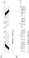
CPU311は、センサ部60の受光素子204が出力する、受光した拡散反射光量に応じた検出電圧を閾値判定することにより各色部分の境界を判定し、これにより、各色間の相対的な位置ずれ量を検出する。ここで、中間転写ベルト80の表面からの拡散反射光は少ないため、センサ部60の検出領域に検出パターンが無い場合、受光素子204の検出電圧は低くなる。この状態で、図5(A)のイエローの部分がセンサ部60の検出領域に移動すると、カラー部分では拡散反射光の受光量が増加するため、受光素子204の検出電圧は上昇する。受光素子204の検出電圧が閾値を超えたときに、CPU311は中間転写ベルト80の表面とカラー部分の境界を越えたと判定する。その後、図5(A)のブラック部分がセンサ部60の検出領域に移動すると、ブラック部分からの拡散反射光は少ないため、受光素子204の検出電圧は減少する。CPU311は、検出電圧が閾値を下回った時にカラー部分とブラック部分の境界を越えたと判定する。その後、再度、受光素子204の検出電圧が上昇し、検出電圧が閾値を超えたときに、CPU311はブラック部分とカラー部分の境界を越えたと判定する。さらに、受光素子204の検出電圧が再度減少し、検出電圧が閾値を下回った時に、CPU311はカラー部分と中間転写ベルト80の表面との境界を越えたと判定する。なお、マゼンダ及びシアンの検出パターンの場合、受光素子204の検出電圧が上昇して閾値を超えたときと、その後の検出電圧の減少により閾値を下回った時に、それぞれ、検出パターン206と中間転写ベルト80の境界を越えたと判定する。   The CPU 311 determines the boundary of each color part by determining the threshold value of the detection voltage according to the received diffuse reflection light amount output from the light receiving element 204 of the sensor unit 60, and thereby the relative positional deviation amount between the colors. Is detected. Here, since the diffuse reflection light from the surface of the intermediate transfer belt 80 is small, the detection voltage of the light receiving element 204 is low when there is no detection pattern in the detection region of the sensor unit 60. In this state, when the yellow part in FIG. 5A moves to the detection region of the sensor unit 60, the amount of light received by the diffuse reflection light increases in the color part, so that the detection voltage of the light receiving element 204 increases. When the detection voltage of the light receiving element 204 exceeds the threshold value, the CPU 311 determines that the boundary between the surface of the intermediate transfer belt 80 and the color portion has been exceeded. Thereafter, when the black portion in FIG. 5A moves to the detection region of the sensor unit 60, the diffused reflected light from the black portion is small, and the detection voltage of the light receiving element 204 decreases. The CPU 311 determines that the boundary between the color part and the black part has been exceeded when the detection voltage falls below the threshold value. Thereafter, when the detection voltage of the light receiving element 204 increases again and the detection voltage exceeds the threshold, the CPU 311 determines that the boundary between the black portion and the color portion has been exceeded. Further, when the detection voltage of the light receiving element 204 decreases again and the detection voltage falls below the threshold value, the CPU 311 determines that the boundary between the color portion and the surface of the intermediate transfer belt 80 has been exceeded. In the case of magenta and cyan detection patterns, the detection pattern 206 and the intermediate transfer belt are respectively detected when the detection voltage of the light receiving element 204 rises and exceeds the threshold value, and when the detection voltage decreases below the threshold value. It is determined that 80 boundaries have been exceeded.

したがって、検出パターン206のカラー部分を検知しているときの受光素子204の検出電圧は閾値より大きくなければならない。また、ブラック部分を検知しているときの受光素子204の検出電圧は閾値より小さくなければならない。   Therefore, the detection voltage of the light receiving element 204 when detecting the color portion of the detection pattern 206 must be larger than the threshold value. Further, the detection voltage of the light receiving element 204 when detecting the black portion must be smaller than the threshold value.

また、濃度制御時、CPU311は、センサ部60の受光素子205が受光する正反射光及び受光素子204が受光する拡散反射光により濃度を判定する。ここで、受光素子204の出力や、出力をデジタル変換する際のA/D変換器において飽和が発生すると濃度の検出ができなくなる。したがって、飽和が発生しない検出電圧の上限値、つまり、受光素子204が受光できる上限値を決定し、図5(B)に示す様に、受光素子204の検出電圧が上限値未満となる様にしなければならない。   At the time of density control, the CPU 311 determines the density based on regular reflection light received by the light receiving element 205 of the sensor unit 60 and diffuse reflection light received by the light receiving element 204. Here, if saturation occurs in the output of the light receiving element 204 or in the A / D converter when digitally converting the output, the density cannot be detected. Therefore, the upper limit value of the detection voltage at which saturation does not occur, that is, the upper limit value at which the light receiving element 204 can receive light is determined, and the detection voltage of the light receiving element 204 becomes less than the upper limit value as shown in FIG. There must be.

例えば、カラー部分の濃度が薄く、かつ、発光素子203の光量が少ないことにより、カラー部分検出時の受光素子204の検出電圧が閾値を越えない場合、CPU311は、検出パターン206の位置を検出することができなくなる。また、ブラック部分の濃度が薄く、かつ、発光素子203の光量が多いことにより、ブラック部分検出時の受光素子204の検出電圧が閾値を下回らない場合にも、CPU311は、検出パターン206の位置を検出することができなくなる。さらに、発光素子203の光量が多いことにより、検出パターン207検出時の受光素子204の検出電圧が飽和する場合には、濃度を検出することができなくなる。   For example, the CPU 311 detects the position of the detection pattern 206 when the density of the color portion is low and the detection voltage of the light receiving element 204 at the time of detecting the color portion does not exceed the threshold because the light amount of the light emitting element 203 is small. I can't do that. Further, even when the detection voltage of the light receiving element 204 at the time of detecting the black part does not fall below the threshold due to the low density of the black part and the light quantity of the light emitting element 203, the CPU 311 determines the position of the detection pattern 206. It cannot be detected. Further, when the detection voltage of the light receiving element 204 at the time of detecting the detection pattern 207 is saturated due to the large amount of light of the light emitting element 203, the density cannot be detected.

位置ずれの検出パターン206は、通常、最大濃度で形成する。しかし、検出パターン206のトナー像の表面の状態は一様ではないため、拡散反射光には、ばらつきが生じる。よって、このばらつきを考慮した上で、受光素子204が検出するカラー部分の最小電圧値と、ブラック部分の最大電圧値を、補正制御の開始によりまず求める。この場合、求めた各電圧値が以下の条件を満たせば、位置検出ができなくなることを防ぐことができる。
カラー部分検出時の最小電圧値 > 閾値 (1)
ブラック部分検出時の最大電圧値 < 閾値 (2)
The misregistration detection pattern 206 is usually formed with the maximum density. However, since the state of the surface of the toner image of the detection pattern 206 is not uniform, the diffuse reflected light varies. Therefore, in consideration of this variation, the minimum voltage value of the color portion and the maximum voltage value of the black portion detected by the light receiving element 204 are first obtained by starting correction control. In this case, if the obtained voltage values satisfy the following conditions, it can be prevented that position detection cannot be performed.
Minimum voltage value when color part is detected> threshold (1)
Maximum voltage when black part is detected <threshold (2)

同様に、受光素子204が検出する濃度の検出パターン207の最大電圧値を測定により求める。この場合、求めた各電圧値が以下の条件を満たせば、濃度検出ができなくなることを防ぐことができる。
検出パターン207検出時の最大電圧値 < 受光素子204の受光量の上限値 (3)
Similarly, the maximum voltage value of the density detection pattern 207 detected by the light receiving element 204 is obtained by measurement. In this case, if the obtained voltage values satisfy the following conditions, it is possible to prevent the concentration from being detected.
Maximum voltage value at detection pattern 207 detection <Upper limit value of light reception amount of light receiving element 204 (3)

なお、濃度検出において、拡散反射光が最大となるのは、最大濃度のトナー像を形成したときであり、位置検出の検出パターン206は最大濃度で形成することから、式(3)の条件は、
カラー部分検出時の最大電圧値 < 受光素子204の受光量の上限値 (4)
との条件に置きかえることができる。
In the density detection, the diffuse reflected light becomes maximum when the toner image having the maximum density is formed, and the detection pattern 206 for position detection is formed with the maximum density. ,
Maximum voltage value at color portion detection <Upper limit value of received light amount of light receiving element 204 (4)
It can be replaced with the condition.

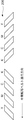
続いて、図6を用いて、式(1)、(2)及び(4)を満たす様に発光素子203の光量を変更する方法を説明する。図6において開始光量とは、発光素子203への電流を増加させたときに、初めて発光を開始する点である。なお、本実施形態においては、点616の開始光量及び受光素子204の暗電圧については、予め図示しない記憶部に保存しておくものとする。点616は、開始光量における検出電圧が暗電圧であることを示し、以下に述べる発光光量制御の基準値となる。なお、本実施形態においては、閾値は予め決められており、センサ部60の感度も、予め決められた値であるものとする。点614は、発光素子203を任意の測定光量にしてセンサ部60が検出したカラー部分の最小電圧値を示す点である。点614と点616を結ぶ直線611は、発光素子203の光量と、カラー部分検出時のセンサ部60の最小電圧値との関係を示すものとなる。式(1)より、発光素子203は、直線611が閾値より上となる光量は使用できるが、閾値以下となる光量は使用できない。よって、符号621で示す位置の光量は、発光素子203の最小光量となる。   Next, a method of changing the light amount of the light emitting element 203 so as to satisfy the expressions (1), (2), and (4) will be described with reference to FIG. In FIG. 6, the starting light amount is a point at which light emission starts for the first time when the current to the light emitting element 203 is increased. In the present embodiment, it is assumed that the light intensity at the point 616 and the dark voltage of the light receiving element 204 are stored in advance in a storage unit (not shown). A point 616 indicates that the detection voltage at the start light amount is a dark voltage, and is a reference value for the light emission amount control described below. In the present embodiment, the threshold value is determined in advance, and the sensitivity of the sensor unit 60 is also a predetermined value. A point 614 is a point indicating the minimum voltage value of the color portion detected by the sensor unit 60 with the light emitting element 203 as an arbitrary measurement light amount. A straight line 611 connecting the points 614 and 616 indicates the relationship between the light amount of the light emitting element 203 and the minimum voltage value of the sensor unit 60 when the color portion is detected. According to the expression (1), the light emitting element 203 can use the light amount with which the straight line 611 is above the threshold value, but cannot use the light amount with the threshold value or less. Accordingly, the light amount at the position indicated by reference numeral 621 is the minimum light amount of the light emitting element 203.

同様に、点615は、発光素子203を任意の測定光量にしてセンサ部60が検出したブラック部分の最大電圧値を示す点である。点616と点615を結ぶ直線612は、発光素子203の光量と、ブラック部分検出時のセンサ部60の最大電圧値との関係を示すものとなる。式(2)より、発光素子203は、直線612が閾値未満となる光量は使用できるが、閾値以上となる光量は使用できない。よって、発光素子203は、少なくとも、符号622で示す光量より小さい光量としなければならない。以下、符号622の位置の光量を最大光量候補と呼ぶものとする。   Similarly, a point 615 is a point indicating the maximum voltage value of the black portion detected by the sensor unit 60 with the light emitting element 203 as an arbitrary measurement light amount. A straight line 612 connecting the points 616 and 615 indicates the relationship between the light amount of the light emitting element 203 and the maximum voltage value of the sensor unit 60 when the black portion is detected. According to Expression (2), the light emitting element 203 can use the light amount that the straight line 612 is less than the threshold value, but cannot use the light amount that is the threshold value or more. Therefore, the light emitting element 203 must have a light amount smaller than at least the light amount indicated by reference numeral 622. Hereinafter, the light quantity at the position indicated by reference numeral 622 is referred to as a maximum light quantity candidate.

さらに、点613は、発光素子203を任意の測定光量にしてセンサ部60が検出したカラー部分の最大電圧値を示す点である。点616と点613を結ぶ直線610は、発光素子203の光量と、カラー部分検出時のセンサ部60の最大電圧値との関係を示すものとなる。式(4)より、発光素子203は、直線610が上限値未満となる光量は使用できるが、上限値以上となる光量は使用できない。よって、発光素子203は、少なくとも、符号620で示す光量より小さい光量としなければならない。以下、符号620の位置の光量を最大光量候補と呼ぶものとする。   Further, a point 613 is a point indicating the maximum voltage value of the color portion detected by the sensor unit 60 with the light emitting element 203 as an arbitrary measurement light amount. A straight line 610 connecting the points 616 and 613 shows the relationship between the light amount of the light emitting element 203 and the maximum voltage value of the sensor unit 60 when the color portion is detected. According to the equation (4), the light emitting element 203 can use the light amount with which the straight line 610 is less than the upper limit value, but cannot use the light amount with the upper limit value or more. Therefore, the light emitting element 203 must have a light amount smaller than at least the light amount indicated by reference numeral 620. Hereinafter, the light amount at the position indicated by reference numeral 620 is referred to as a maximum light amount candidate.

したがって、図6に示す状態である場合、発光素子203に設定可能な光量の下限は符号621で示す最小光量(第2の発光量)となる。一方、発光素子203に設定可能な光量の上限は符号620で示す最大光量候補(第1の発光量)及び符号622で示す最大光量候補(第3の発光量)の小さい方となる。図6の例では、符号620で示す位置の光量が最大光量となる。よって、発光素子203に設定可能な光量の範囲は符号617で示す範囲となる。本実施形態においては、最小光量と最大光量の間の光量、例えば中間の光量を、発光素子203の光量に設定するが、最小光量と最大光量の間であれば、任意の光量に設定可能である。   Therefore, in the state shown in FIG. 6, the lower limit of the light amount that can be set in the light emitting element 203 is the minimum light amount (second light emission amount) indicated by reference numeral 621. On the other hand, the upper limit of the light amount that can be set in the light emitting element 203 is the smaller of the maximum light amount candidate (first light emission amount) indicated by reference numeral 620 and the maximum light amount candidate (third light emission amount) indicated by reference numeral 622. In the example of FIG. 6, the light quantity at the position indicated by reference numeral 620 is the maximum light quantity. Therefore, the range of the amount of light that can be set in the light emitting element 203 is a range indicated by reference numeral 617. In the present embodiment, a light amount between the minimum light amount and the maximum light amount, for example, an intermediate light amount is set as the light amount of the light emitting element 203, but any light amount can be set as long as it is between the minimum light amount and the maximum light amount. is there.

図7は、第一実施形態においてエンジン制御部302が実行する発光素子203の光量設定のフローチャートである。CPU311は、位置ずれ及び濃度検出制御の開始により、S10において、各検出パターンを画像形成部に形成させる。S11において、CPU311は、検出パターン206のカラー部分の検出電圧の最小値及び最大値と、ブラック部分の検出電圧の最大値を取得する。S12において、CPU311は、カラー部分の検出電圧の最小値により最小光量を判定する。S13において、CPU311は、カラー部分の検出電圧の最大値と、ブラック部分の検出電圧の最大値により、上述した様に最大光量を判定する。最後に、CPU311は、S14において、最小光量と最大光量の間の光量を発光素子203に設定する光量に決定する。一例として、最小光量と最大光量の中間の光量を発光素子203に設定することができる。なお、上記処理を行った後、CPU311は、形成した検出パターンにより位置ずれ及び濃度補正を実行する。   FIG. 7 is a flowchart of light amount setting of the light emitting element 203 executed by the engine control unit 302 in the first embodiment. In step S10, the CPU 311 causes the image forming unit to form each detection pattern by starting the positional deviation and density detection control. In S <b> 11, the CPU 311 acquires the minimum value and the maximum value of the detection voltage of the color portion of the detection pattern 206 and the maximum value of the detection voltage of the black portion. In S12, the CPU 311 determines the minimum light amount based on the minimum value of the detection voltage of the color portion. In S13, the CPU 311 determines the maximum light amount as described above based on the maximum value of the detection voltage of the color portion and the maximum value of the detection voltage of the black portion. Finally, in S14, the CPU 311 determines a light amount between the minimum light amount and the maximum light amount as a light amount to be set in the light emitting element 203. As an example, an intermediate light amount between the minimum light amount and the maximum light amount can be set in the light emitting element 203. Note that after performing the above processing, the CPU 311 executes positional deviation and density correction by the formed detection pattern.

以上の構成により、位置ずれ検出と濃度検出を連続して実行するための発光素子203の発光量を決定して設定することができる。   With the above configuration, it is possible to determine and set the light emission amount of the light emitting element 203 for continuously executing the positional deviation detection and the density detection.

(第二実施形態)第一実施形態は、位置ずれ及び濃度の検出の両方に使用する拡散反射光の受光素子204の受光量により発光素子203の光量を設定するものであった。本実施形態においては、受光素子205が受光する正反射光の受光量により位置ずれを決定する。よって、両方の制御で使用する正反射光の受光素子205の受光量により発光素子203の光量を設定する。なお、以下では、第一実施形態との相違点を中心に説明し、画像形成装置の構成等、第一実施形態と同様な部分については説明を省略する。   (Second Embodiment) In the first embodiment, the amount of light emitted from the light emitting element 203 is set according to the amount of diffusely reflected light received by the light receiving element 204 used for both positional deviation and density detection. In the present embodiment, the positional deviation is determined based on the amount of regular reflection light received by the light receiving element 205. Therefore, the light quantity of the light emitting element 203 is set according to the amount of light received by the light receiving element 205 of regular reflection light used in both controls. In the following description, differences from the first embodiment will be mainly described, and description of parts similar to those of the first embodiment such as the configuration of the image forming apparatus will be omitted.

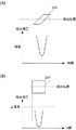
本実施形態においては、位置ずれ検出のために、図4(A)の検出パターン206に代えて、図8に示す検出パターン206を使用する。図8の検出パターンは、イエローのトナー像の上にブラックのトナー像を形成するのではなく、それぞれ、個別に形成する点で、図4(A)の検出パターン206とは異なる。   In the present embodiment, a detection pattern 206 shown in FIG. 8 is used in place of the detection pattern 206 shown in FIG. The detection pattern shown in FIG. 8 is different from the detection pattern 206 shown in FIG. 4A in that a black toner image is not formed on a yellow toner image but is formed individually.

検出パターン206での正反射光は、中間転写ベルト80の表面での正反射光より小さく、かつ、検出パターン206の濃度が濃いほど小さくなる。よって、図9(A)に示す様に、検出パターン206を検出しているときの受光素子205の検出電圧は、中間転写ベルト80の表面を検出している場合より小さくなる。よって、受光素子205の検出電圧が閾値未満のとき、CPU311は検出パターン206を検出していると判定する。つまり、中間転写ベルト80の表面を検出しているときの受光素子205の検出電圧は閾値より大きく、かつ、検出パターン206を検出しているときの受光素子205の検出電圧は閾値より小さくなければならない。   The regular reflection light on the detection pattern 206 is smaller than the regular reflection light on the surface of the intermediate transfer belt 80 and becomes smaller as the density of the detection pattern 206 is higher. Therefore, as shown in FIG. 9A, the detection voltage of the light receiving element 205 when detecting the detection pattern 206 is smaller than that when the surface of the intermediate transfer belt 80 is detected. Therefore, when the detection voltage of the light receiving element 205 is less than the threshold, the CPU 311 determines that the detection pattern 206 is detected. That is, the detection voltage of the light receiving element 205 when detecting the surface of the intermediate transfer belt 80 must be greater than the threshold value, and the detection voltage of the light receiving element 205 when detecting the detection pattern 206 must be less than the threshold value. Don't be.

また、図9(B)に示す様に、濃度検出のためには、濃度の検出パターン207を検出しているときの受光素子205の検出電圧は、受光素子205の検出電圧の上限値、つまり、受光素子205が受光できる上限値より小さくなければならない。   Further, as shown in FIG. 9B, for density detection, the detection voltage of the light receiving element 205 when detecting the density detection pattern 207 is the upper limit value of the detection voltage of the light receiving element 205, that is, The light receiving element 205 must be smaller than the upper limit value capable of receiving light.

中間転写ベルト80や検出パターンからの正反射光は、中間転写ベルト80や検出パターンの表面状態が一様ではないためばらつきが生じる。よって、このばらつきを考慮した上で、受光素子205が検出する中間転写ベルト80の最小電圧値と、位置ずれの検出パターン206の最大電圧値を測定により求める。この場合、求めた各電圧値が以下の条件を満たせば、位置検出ができなくなることを防ぐことができる。
中間転写ベルト表面検出時の最小電圧値 > 閾値 (5)
検出パターン206検出時の最大電圧値 < 閾値 (6)
The regular reflection light from the intermediate transfer belt 80 and the detection pattern varies because the surface state of the intermediate transfer belt 80 and the detection pattern is not uniform. Therefore, in consideration of this variation, the minimum voltage value of the intermediate transfer belt 80 detected by the light receiving element 205 and the maximum voltage value of the misregistration detection pattern 206 are obtained by measurement. In this case, if the obtained voltage values satisfy the following conditions, it can be prevented that position detection cannot be performed.
Minimum voltage when detecting the surface of the intermediate transfer belt> threshold (5)
Maximum voltage value at detection pattern 206 detection <threshold value (6)

同様に、受光素子205が検出する濃度の検出パターン207の最大電圧値を測定により求める。この場合、求めた電圧値が以下の条件を満たせば、濃度検出ができなくなることを防ぐことができる。
検出パターン207検出時の最大電圧値 < 受光素子205の受光量の上限値(7)
Similarly, the maximum voltage value of the density detection pattern 207 detected by the light receiving element 205 is obtained by measurement. In this case, if the obtained voltage value satisfies the following conditions, it is possible to prevent the concentration from being detected.
Maximum voltage value when detecting pattern 207 is detected <Upper limit value of received light amount of light receiving element 205 (7)

なお、正反射光が最大となるのは、中間転写ベルト80表面の検出時であり、よって、式(7)の条件は、
中間転写ベルト表面検出時の最大電圧値 < 受光素子205の受光量の上限値(8)
との条件に置きかえることができる。
The specularly reflected light is maximized when the surface of the intermediate transfer belt 80 is detected. Therefore, the condition of the expression (7) is
Maximum voltage value at the time of detecting the surface of the intermediate transfer belt <Upper limit value of received light amount of light receiving element 205 (8)
It can be replaced with the condition.

続いて、図10を用いて、式(5)、(6)及び(8)を満たす様に発光素子203の光量を変更する方法を説明する。点916は既に説明した開始光量である。なお、本実施形態においても、点916の開始光量及び暗電圧については、予め図示しない記憶部に保存しておくものとする。また、点914は、発光素子203を任意の測定光量に設定し、受光素子205が中間転写ベルト80表面を検出しているときの最小電圧値を示す点である。点914と点916を結ぶ直線911は、発光素子203の光量と、中間転写ベルト80表面検出時の最小電圧値との関係を示すものとなる。式(5)より、発光素子203は、直線911が閾値より上となる光量は使用できるが、閾値以下となる光量は使用できない。よって、符号921で示す位置の光量は、発光素子203の最小光量となる。   Next, a method of changing the light amount of the light emitting element 203 so as to satisfy the expressions (5), (6), and (8) will be described with reference to FIG. A point 916 is the start light quantity already described. Also in this embodiment, the starting light quantity and dark voltage at point 916 are stored in advance in a storage unit (not shown). A point 914 indicates a minimum voltage value when the light emitting element 203 is set to an arbitrary measurement light amount and the light receiving element 205 detects the surface of the intermediate transfer belt 80. A straight line 911 connecting the points 914 and 916 indicates the relationship between the light amount of the light emitting element 203 and the minimum voltage value when the surface of the intermediate transfer belt 80 is detected. According to Expression (5), the light emitting element 203 can use the light amount that the straight line 911 is above the threshold value, but cannot use the light amount that is less than the threshold value. Therefore, the light amount at the position indicated by reference numeral 921 is the minimum light amount of the light emitting element 203.

同様に、点915は、発光素子203を任意の測定光量に設定したときの、受光素子205による検出パターン206検出時の最大電圧値を示す点である。点916と点915を結ぶ直線912は、発光素子203の光量と、検出パターン206を検出しているときの最大電圧値との関係を示すものとなる。式(6)より、発光素子203は、直線912が閾値未満となる光量は使用できるが、閾値以上となる光量は使用できない。よって、発光素子203は、少なくとも、符号922で示す光量より小さい光量としなければならない。以下、符号922の位置の光量を最大光量候補と呼ぶものとする。   Similarly, a point 915 is a point indicating the maximum voltage value when the detection pattern 206 is detected by the light receiving element 205 when the light emitting element 203 is set to an arbitrary measurement light amount. A straight line 912 connecting the points 916 and 915 indicates the relationship between the light amount of the light emitting element 203 and the maximum voltage value when the detection pattern 206 is detected. From Expression (6), the light emitting element 203 can use the light amount that the straight line 912 is less than the threshold value, but cannot use the light amount that exceeds the threshold value. Therefore, the light emitting element 203 must have a light amount smaller than at least the light amount indicated by reference numeral 922. Hereinafter, the light quantity at the position indicated by reference numeral 922 is referred to as a maximum light quantity candidate.

さらに、点913は、発光素子203を任意の測定光量に設定したときの、受光素子205が中間転写ベルト80表面を検出しているときの最大電圧値を示す点である。点916と点913を結ぶ直線910は、発光素子203の光量と、中間転写ベルト80表面を検出している時の最大電圧値との関係を示すものとなる。式(8)より、発光素子203は、直線913が上限値未満となる光量は使用できるが、上限値以上となる光量は使用できない。よって、発光素子203は、少なくとも、符号920で示す光量より小さい光量としなければならない。以下、符号920の位置の光量を最大光量候補と呼ぶものとする。   Further, a point 913 is a point indicating a maximum voltage value when the light receiving element 205 detects the surface of the intermediate transfer belt 80 when the light emitting element 203 is set to an arbitrary measurement light amount. A straight line 910 connecting the points 916 and 913 shows the relationship between the light amount of the light emitting element 203 and the maximum voltage value when the surface of the intermediate transfer belt 80 is detected. According to the equation (8), the light emitting element 203 can use the light amount with which the straight line 913 is less than the upper limit value, but cannot use the light amount with the upper limit value or more. Therefore, the light emitting element 203 must have a light amount smaller than at least the light amount indicated by reference numeral 920. Hereinafter, the light quantity at the position indicated by reference numeral 920 is referred to as a maximum light quantity candidate.

CPU311は、第一実施形態と同様に最大光量候補の小さい方を最大光量とする。第一実施形態と同様、発光素子203に設定可能な光量の範囲は、符号917で示す最小光量より大きく最大光量未満の範囲となる。なお、本実施形態においては、最小光量と最大光量の中間の光量を、発光素子203の光量に設定するが、最小光量と最大光量の間であれば、任意の光量に設定可能である。   As in the first embodiment, the CPU 311 sets the smaller maximum light amount candidate as the maximum light amount. As in the first embodiment, the range of the light amount that can be set in the light emitting element 203 is a range that is larger than the minimum light amount indicated by reference numeral 917 and less than the maximum light amount. In the present embodiment, an intermediate light amount between the minimum light amount and the maximum light amount is set to the light amount of the light emitting element 203, but any light amount can be set as long as it is between the minimum light amount and the maximum light amount.

図11は、第二実施形態においてエンジン制御部302が実行する発光素子203の光量設定のフローチャートである。CPU311は、位置ずれ及び濃度検出制御の開始により、S20において、各検出パターンを画像形成部に形成させる。S21において、CPU311は、受光素子205による中間転写ベルト80表面検出時の検出電圧の最小値及び最大値と、位置ずれの検出パターン206検出時の検出電圧の最大値を取得する。S22において、CPU311は、中間転写ベルト80表面検出時の受光素子205の検出電圧の最小値より最小光量を判定する。S23において、CPU311は、中間転写ベルト80検出時の受光素子205の検出電圧の最大値と、検出パターン206検出時の受光素子205の検出電圧の最大値により、最大光量を判定する。最後に、CPU311は、S24において、最小光量と最大光量の間の光量を発光素子203に設定する光量に決定する。一例として、最小光量と最大光量の中間の光量を発光素子203に設定することができる。   FIG. 11 is a flowchart of light amount setting of the light emitting element 203 executed by the engine control unit 302 in the second embodiment. In step S20, the CPU 311 causes the image forming unit to form each detection pattern by starting the positional deviation and density detection control. In step S <b> 21, the CPU 311 acquires the minimum value and the maximum value of the detection voltage when the surface of the intermediate transfer belt 80 is detected by the light receiving element 205 and the maximum value of the detection voltage when the misregistration detection pattern 206 is detected. In S <b> 22, the CPU 311 determines the minimum light amount from the minimum value of the detection voltage of the light receiving element 205 when the surface of the intermediate transfer belt 80 is detected. In S <b> 23, the CPU 311 determines the maximum light amount based on the maximum value of the detection voltage of the light receiving element 205 when the intermediate transfer belt 80 is detected and the maximum value of the detection voltage of the light receiving element 205 when detecting the detection pattern 206. Finally, in S24, the CPU 311 determines a light amount between the minimum light amount and the maximum light amount as a light amount to be set in the light emitting element 203. As an example, an intermediate light amount between the minimum light amount and the maximum light amount can be set in the light emitting element 203.

以上の構成により、位置ずれ検出と濃度検出を連続して実行するための発光素子203の発光量を決定して設定することができる。   With the above configuration, it is possible to determine and set the light emission amount of the light emitting element 203 for continuously executing the positional deviation detection and the density detection.

(第三実施形態)第一実施形態及び第二実施形態は、受光素子204又は205の受光光量により発光素子203の光量を設定するものであった。しかしながら、いずれか一方の受光素子を使用して、発光素子203の光量を変更すると、他方の受光素子の受光光量も変化し、例えば、他方の受光素子の受光量が受光範囲外となることが生じ得る。本実施形態は、第一実施形態の構成において、受光素子205の検出電圧、つまり正反射光の受光量も考慮して発光素子203の光量の設定を行うものである。なお、以下では、第一実施形態との相違点を中心に説明し、画像形成装置の構成等、第一実施形態と同様な部分については説明を省略する。   (Third Embodiment) In the first embodiment and the second embodiment, the light quantity of the light emitting element 203 is set according to the received light quantity of the light receiving element 204 or 205. However, if the light quantity of the light emitting element 203 is changed by using one of the light receiving elements, the light quantity of the other light receiving element also changes, for example, the amount of light received by the other light receiving element may be outside the light receiving range. Can occur. In the present embodiment, in the configuration of the first embodiment, the light amount of the light emitting element 203 is set in consideration of the detection voltage of the light receiving element 205, that is, the amount of received regular reflected light. In the following description, differences from the first embodiment will be mainly described, and description of parts similar to those of the first embodiment such as the configuration of the image forming apparatus will be omitted.

本実施形態は、第一実施形態における式(1)、式(2)及び式(4)の条件に加えて、第二実施形態における式(8)を条件とすることで、発光素子203の光量を設定するものである。   In the present embodiment, in addition to the conditions of the expressions (1), (2), and (4) in the first embodiment, the condition of the expression (8) in the second embodiment is used. Sets the amount of light.

続いて、図12を用いて、式(1)、(2)、(4)及び式(8)を満たす様に発光素子203の光量を変更する方法を説明する。なお、図12は、図6のグラフに、式(8)に関する関係を追加したものであり、図6にて説明した内容については再度の説明を省略する。   Next, a method for changing the light amount of the light emitting element 203 so as to satisfy Expressions (1), (2), (4), and Expression (8) will be described with reference to FIG. Note that FIG. 12 is obtained by adding the relationship regarding the expression (8) to the graph of FIG. 6, and the description of the contents described in FIG. 6 is omitted.

図12の符号670は、受光素子205の開始光量と暗電圧の関係を示している。つまり、点670は、図10の点916に対応するものである。点671は、任意の測定光量において、中間転写ベルト80表面検出時の受光素子205の最大電圧値を示す点である。点671と点670を結ぶ直線672は、発光素子203の光量と、受光素子205が検出する中間転写ベルト80の最大電圧値との関係を示すものとなる。式(8)より、発光素子203は、直線672が、受光素子205の上限値未満となる光量は使用できるが、受光素子205の上限値以上となる光量は使用できない。よって、符号673で示す光量も、符号622及び620で示す光量と共に発光素子203の最大光量候補となる。   Reference numeral 670 in FIG. 12 indicates the relationship between the starting light amount of the light receiving element 205 and the dark voltage. That is, the point 670 corresponds to the point 916 in FIG. A point 671 is a point indicating the maximum voltage value of the light receiving element 205 when the surface of the intermediate transfer belt 80 is detected with an arbitrary measurement light amount. A straight line 672 connecting the points 671 and 670 shows the relationship between the light amount of the light emitting element 203 and the maximum voltage value of the intermediate transfer belt 80 detected by the light receiving element 205. From Expression (8), the light emitting element 203 can use a light amount for which the straight line 672 is less than the upper limit value of the light receiving element 205, but cannot use a light amount that exceeds the upper limit value of the light receiving element 205. Therefore, the light quantity indicated by reference numeral 673 is also the maximum light quantity candidate of the light emitting element 203 together with the light quantities indicated by reference numerals 622 and 620.

したがって、図12に示す状態である場合、発光素子203に設定可能な光量の下限は符号621で示す最小光量となる。一方、発光素子203に設定可能な光量の上限は符号620、622及び673で示す3つの最大光量候補の最も小さいものとなる。つまり、符号673で示す位置の光量が最大光量となる。よって、発光素子203に設定可能な光量の範囲は符号617で示す範囲となる。本実施形態においては、最小光量と最大光量の中間の光量を、発光素子203の光量に設定するが、最小光量と最大光量の間であれば、任意の光量に設定可能である。   Accordingly, in the state shown in FIG. 12, the lower limit of the light amount that can be set in the light emitting element 203 is the minimum light amount indicated by reference numeral 621. On the other hand, the upper limit of the light quantity that can be set in the light emitting element 203 is the smallest of the three maximum light quantity candidates indicated by reference numerals 620, 622, and 673. That is, the light amount at the position indicated by reference numeral 673 is the maximum light amount. Therefore, the range of the amount of light that can be set in the light emitting element 203 is a range indicated by reference numeral 617. In the present embodiment, an intermediate light amount between the minimum light amount and the maximum light amount is set to the light amount of the light emitting element 203, but any light amount can be set as long as it is between the minimum light amount and the maximum light amount.

図13は、第三実施形態においてエンジン制御部302が実行する発光素子203の光量設定のフローチャートである。CPU311は、位置ずれ及び濃度検出制御の開始により、S30において、各検出パターンを画像形成部に形成させる。S31において、CPU311は、受光素子204が検出するカラー部分の検出電圧の最小値及び最大値と、ブラック部分の検出電圧の最大値を取得する。さらに、受光素子205が検出する中間転写ベルト80表面の検出電圧の最大値を取得する。S32において、CPU311は、カラー部分の検出電圧の最小値により最小光量を判定する。S33において、CPU311は、カラー部分の検出電圧の最大値と、ブラック部分の検出電圧の最大値と、中間転写ベルト80の検出電圧の最大値から、上述した様に最大光量を判定する。最後に、CPU311は、S34において、最小光量と最大光量の間の光量を発光素子203に設定する光量に決定する。   FIG. 13 is a flowchart of light amount setting of the light emitting element 203 executed by the engine control unit 302 in the third embodiment. In step S30, the CPU 311 causes the image forming unit to form each detection pattern by starting the misregistration and density detection control. In S31, the CPU 311 obtains the minimum value and the maximum value of the detection voltage of the color portion detected by the light receiving element 204 and the maximum value of the detection voltage of the black portion. Further, the maximum value of the detection voltage on the surface of the intermediate transfer belt 80 detected by the light receiving element 205 is acquired. In S32, the CPU 311 determines the minimum light amount based on the minimum value of the detection voltage of the color portion. In step S <b> 33, the CPU 311 determines the maximum light amount as described above from the maximum value of the detection voltage of the color portion, the maximum value of the detection voltage of the black portion, and the maximum value of the detection voltage of the intermediate transfer belt 80. Finally, in S34, the CPU 311 determines a light amount between the minimum light amount and the maximum light amount as a light amount to be set in the light emitting element 203.

以上の構成により、位置ずれ検出と濃度検出を連続して実行するための発光素子203の発光量を決定して設定することができる。   With the above configuration, it is possible to determine and set the light emission amount of the light emitting element 203 for continuously executing the positional deviation detection and the density detection.

なお、上記各実施形態において、正反射光や拡散反射光のばらつきを考慮して、受光素子204及び205が検出する検出電圧の最大値や最小値を求めたが本発明はこれに限定されない。つまり、1回の測定の値を使用する構成であっても良い。また、複数回の測定の最大値や最小値ではなく平均値等を使用する構成であっても良い。   In each of the above-described embodiments, the maximum value and the minimum value of the detection voltage detected by the light receiving elements 204 and 205 are obtained in consideration of variations in regular reflection light and diffuse reflection light, but the present invention is not limited to this. That is, a configuration using a single measurement value may be used. Moreover, the structure which uses an average value etc. instead of the maximum value and minimum value of several times of measurement may be sufficient.

(第四実施形態)第一実施形態から第三実施形態は、受光素子204又は205の受光光量により発光素子203の光量を設定するものであった。本実施形態では、受光素子204の受光感度を変更することで、同時に位置ずれ検出と濃度検出を成功させる方法を説明する。なお、以下では、第一実施形態との相違点を中心に説明し、画像形成装置の構成等、第一実施形態と同様な部分については説明を省略する。   (Fourth Embodiment) In the first embodiment to the third embodiment, the light quantity of the light emitting element 203 is set by the received light quantity of the light receiving element 204 or 205. In the present embodiment, a method will be described in which the detection of the positional deviation and the concentration detection are performed simultaneously by changing the light receiving sensitivity of the light receiving element 204. In the following description, differences from the first embodiment will be mainly described, and description of parts similar to those of the first embodiment such as the configuration of the image forming apparatus will be omitted.

図14は、センサ部60の受光素子204の受光感度を変更する構成を示している。CPU311からの駆動信号Vledonは、ベース抵抗1403を介してトランジスタなどのスイッチング素子1404を駆動し、電流制限抵抗1405で発光素子203に流れる電流を制御することで発光制御を行う。中間転写ベルト80及び検出パターンからの拡散反射光を受光素子204で検出し、検出した反射光量に応じた光電流が抵抗1401に流れることにより、反射光量は、アナログ信号として検出される。分圧抵抗1406及び1407で設定する所望の閾値電圧である基準電圧と、検出したアナログ信号とをコンパレータ1402などを用いて比較することにより、アナログ信号はデジタル信号Vdoutに変換される。Vdoutは、例えば、CPU311に入力され、CPU311は、Vdoutの変化から検出パターン206の各色の境界を検出する。つまり、閾値電圧は、例えば、図6に示す位置ずれの検出パターン206を検出するための閾値に対応する。感度調整部1408は、トランジスタなどを用いてコンパレータ1402に入力されるアナログ信号を分圧することで、その電圧レベルを調整する。つまり、感動調整部1406は、受光素子204の受光感度(ゲイン)を変更する。   FIG. 14 shows a configuration for changing the light receiving sensitivity of the light receiving element 204 of the sensor unit 60. The drive signal Vledon from the CPU 311 drives the switching element 1404 such as a transistor via the base resistor 1403 and controls light emission by controlling the current flowing through the light emitting element 203 with the current limiting resistor 1405. The diffuse reflected light from the intermediate transfer belt 80 and the detection pattern is detected by the light receiving element 204, and a photocurrent corresponding to the detected reflected light amount flows through the resistor 1401, whereby the reflected light amount is detected as an analog signal. The analog signal is converted into a digital signal Vdout by comparing the reference voltage, which is a desired threshold voltage set by the voltage dividing resistors 1406 and 1407, with the detected analog signal using the comparator 1402 or the like. For example, Vdout is input to the CPU 311, and the CPU 311 detects the boundary between the colors of the detection pattern 206 from the change in Vdout. That is, the threshold voltage corresponds to, for example, a threshold for detecting the misalignment detection pattern 206 shown in FIG. The sensitivity adjustment unit 1408 adjusts the voltage level by dividing the analog signal input to the comparator 1402 using a transistor or the like. That is, the emotion adjustment unit 1406 changes the light receiving sensitivity (gain) of the light receiving element 204.

図15は、図6のグラフに、各検出電圧との差の値1517から1519を追加したものである。なお、差の値1517は、受光素子204の受光可能な上限値からカラー部分の検出電圧の最大値613を減じたものである。また、差の値1518は、カラー部分の検出電圧の最小値614から閾値を減じたものである。さらに、差の値1519は、閾値からブラック部分の検出電圧の最大値615を減じたものである。なお、図6にて説明した内容については再度の説明を省略する。   FIG. 15 is obtained by adding difference values 1517 to 1519 to the respective detection voltages to the graph of FIG. Note that the difference value 1517 is obtained by subtracting the maximum value 613 of the color portion detection voltage from the upper limit value at which the light receiving element 204 can receive light. The difference value 1518 is obtained by subtracting the threshold value from the minimum value 614 of the color portion detection voltage. Further, the difference value 1519 is obtained by subtracting the maximum value 615 of the black portion detection voltage from the threshold value. Note that the description of FIG. 6 will not be repeated.

図15に示す各値の測定時の感度調整部1408の感度をGとし、開始光量と測定光量の差をXとすると、
最大電圧613−受光素子204の暗電圧=G・α1・X (9)
最小電圧614−受光素子204の暗電圧=G・α2・X (10)
最大電圧615−受光素子204の暗電圧=G・α3・X (11)
となる。なお、α1及びα2はカラー部分からの拡散反射光の反射率及びそのばらつきにより決まる係数であり、α3はブラック部分からの拡散反射光の反射率及びそのばらつきにより決まる係数である。
When the sensitivity of the sensitivity adjustment unit 1408 at the time of measuring each value shown in FIG. 15 is G, and the difference between the starting light quantity and the measured light quantity is X,
Maximum voltage 613-Dark voltage of light receiving element 204 = G · α1 · X (9)
Minimum voltage 614-dark voltage of light receiving element 204 = G · α2 · X (10)
Maximum voltage 615-dark voltage of light receiving element 204 = G · α3 · X (11)
It becomes. Α1 and α2 are coefficients determined by the reflectance of the diffuse reflection light from the color portion and its variation, and α3 is a coefficient determined by the reflectance of the diffuse reflection light from the black portion and its variation.

式(9)〜(11)より、差の値1517、1518及び1519はいずれも感度調整部1408の感度Gの関数となる。本実施形態においては、例えば、差の値1517、1518及び1519の分散が最小になる様に感度Gを設定することで、位置ずれ及び濃度の検出に関するマージンを最適化する。しかしながら、最大値613が上限値を超えず、最小値614が閾値より大きく、最大値615が閾値を超えない任意の感度Gを使用することができる。つまり、各差の値1517、1518及び1519が共に0未満とならない感度Gを使用することができる。なお、分散は、差の値1517、1518及び1519をそれぞれD1、D2、D3とし、D1からD3の平均値をAとすると、
((D1−A)+(D2−A)+(D3−A))/3
である。
From Expressions (9) to (11), the difference values 1517, 1518, and 1519 are all functions of the sensitivity G of the sensitivity adjustment unit 1408. In the present embodiment, for example, the sensitivity G is set so as to minimize the variance of the difference values 1517, 1518, and 1519, thereby optimizing the margins related to misregistration and density detection. However, any sensitivity G where the maximum value 613 does not exceed the upper limit value, the minimum value 614 is greater than the threshold value, and the maximum value 615 does not exceed the threshold value can be used. That is, it is possible to use a sensitivity G in which the difference values 1517, 1518, and 1519 are not less than 0. Note that the variances are as follows: difference values 1517, 1518, and 1519 are D1, D2, and D3, and the average value of D1 to D3 is A.
((D1-A) 2 + (D2-A) 2 + (D3-A) 2) / 3
It is.

図16は、第四実施形態においてエンジン制御部302が実行する受光素子204の感度設定のフローチャートである。CPU311は、位置ずれ及び濃度検出制御開始により、S40において、各検出パターンを画像形成部に形成させる。S41において、CPU311は、受光素子204が検出するカラー部分の検出電圧の最小値及び最大値と、ブラック部分の検出電圧の最大値を取得する。S42において、CPU311は、受光素子204の上限電圧からカラー部分の検出電圧の最大値を減じることで図15の差1517に対応する濃度検知マージンを計算する。S43において、CPU311は、カラー部分の検出電圧の最小値から閾値を減じることにより、図15の差1518に対応するカラー部分の位置ずれ検知マージンを計算する。S44において、CPU311は、閾値からブラック部分の検出電圧の最大値を減じることにより、図15の差1519に対応するブラック部分の位置ずれ検知マージンを計算する。最後に、CPU311は、S45において、例えば、上記3つのマージンの分散が最小になる感度を求める。なお、各マージンが0未満とならない任意の感度とすることができる。   FIG. 16 is a flowchart of sensitivity setting of the light receiving element 204 executed by the engine control unit 302 in the fourth embodiment. The CPU 311 causes the image forming unit to form each detection pattern in S <b> 40 by starting the positional deviation and density detection control. In S41, the CPU 311 acquires the minimum value and the maximum value of the detection voltage of the color portion detected by the light receiving element 204 and the maximum value of the detection voltage of the black portion. In S <b> 42, the CPU 311 calculates a density detection margin corresponding to the difference 1517 in FIG. 15 by subtracting the maximum value of the color portion detection voltage from the upper limit voltage of the light receiving element 204. In S43, the CPU 311 calculates the misalignment detection margin of the color portion corresponding to the difference 1518 in FIG. 15 by subtracting the threshold value from the minimum value of the detection voltage of the color portion. In S <b> 44, the CPU 311 calculates the misalignment detection margin of the black portion corresponding to the difference 1519 in FIG. 15 by subtracting the maximum value of the detection voltage of the black portion from the threshold value. Finally, in S45, for example, the CPU 311 obtains the sensitivity that minimizes the variance of the three margins. In addition, it can be set as the arbitrary sensitivity in which each margin does not become less than zero.

以上の構成により、位置ずれ検出と濃度検出を連続して実行するための受光素子204の感度を決定して設定することができる。なお、拡散反射光の受光素子204ではなく正反射光の受光素子205を使用する場合においても、同様に、受光素子205の感度を調整することにより位置ずれ検出と濃度検出を連続して実行することができる。つまり、第二実施形態における発光光量の制御に代えて、受光素子205の感度を制御することができる。   With the above configuration, it is possible to determine and set the sensitivity of the light receiving element 204 for continuously executing the positional deviation detection and the density detection. In the case where the light receiving element 205 of regular reflection light is used instead of the light receiving element 204 of diffuse reflection light, similarly, the positional deviation detection and the density detection are continuously executed by adjusting the sensitivity of the light receiving element 205. be able to. That is, the sensitivity of the light receiving element 205 can be controlled instead of controlling the amount of emitted light in the second embodiment.

(第五実施形態)第四実施形態は、受光素子の受光感度を変更するものであった。本実施形態は、受光素子の受光感度に加え、閾値も変更することで、同時に位置ずれ検出と濃度検出を成功させる。なお、以下では、第四実施形態との相違点を中心に説明し、画像形成装置の構成等、第四実施形態と同様な部分については説明を省略する。   (Fifth Embodiment) In the fourth embodiment, the light receiving sensitivity of the light receiving element is changed. In the present embodiment, in addition to the light receiving sensitivity of the light receiving element, the threshold value is also changed, so that the positional deviation detection and the density detection are simultaneously successful. In the following description, differences from the fourth embodiment will be mainly described, and description of parts similar to those of the fourth embodiment such as the configuration of the image forming apparatus will be omitted.

図17は、図14に示す検出部に、位置ずれの検出パターン206を検出するための閾値を変更する切替部1409を追加したものである。切替部1409は、トランジスタなどを用いてコンパレータ1402に入力される基準電圧を分圧することで閾値を変更する。   FIG. 17 is obtained by adding a switching unit 1409 for changing a threshold for detecting the misregistration detection pattern 206 to the detection unit shown in FIG. The switching unit 1409 changes the threshold by dividing the reference voltage input to the comparator 1402 using a transistor or the like.

図18は、本実施形態においてエンジン制御部302が実行する閾値及び受光素子の感度設定制御のフローチャートである。なお、S50からS54は、図16のS40からS44と同様であるため説明は省略する。CPU311は、S55において、S52からS54で求めた3つの検知マージンが等しくなるように受光素子204の感度及び閾値を変更する。しかしながら、最大値613が、受光素子204の上限未満であり、閾値が最小値614と最大値615の間にあれば良く、その範囲で閾値及び感度を設定する。   FIG. 18 is a flowchart of threshold value and light receiving element sensitivity setting control executed by the engine control unit 302 in the present embodiment. Note that S50 to S54 are the same as S40 to S44 in FIG. In S55, the CPU 311 changes the sensitivity and threshold value of the light receiving element 204 so that the three detection margins obtained in S52 to S54 are equal. However, the maximum value 613 is less than the upper limit of the light receiving element 204, and the threshold value may be between the minimum value 614 and the maximum value 615, and the threshold value and sensitivity are set within the range.

例えば、最大値613が、受光素子204の上限未満であれば、閾値を最小値614と最大値615の間となる様に調整すれば良い。また、例えば、最大値613が、受光素子204の上限値を超えている場合や、超えていないがマージンが少ない場合いは、十分なマージンを確保できる感度を決定する。その後、CPU311は、決定した感度での最小値615と最小値614の変化を計算し、計算した最小値615と最小値614の間となる閾値を決定することができる。なお、その場合には、例えば、発光素子203の光量は一定としておく。   For example, if the maximum value 613 is less than the upper limit of the light receiving element 204, the threshold value may be adjusted to be between the minimum value 614 and the maximum value 615. For example, when the maximum value 613 exceeds the upper limit value of the light receiving element 204, or when the maximum value 613 does not exceed the upper limit value but the margin is small, the sensitivity that can secure a sufficient margin is determined. Thereafter, the CPU 311 can calculate a change between the minimum value 615 and the minimum value 614 with the determined sensitivity, and can determine a threshold value between the calculated minimum value 615 and the minimum value 614. In that case, for example, the light quantity of the light emitting element 203 is kept constant.

以上の構成により、位置ずれ検出と濃度検出を連続して実行するための受光素子204の受光感度と、位置ずれの検出パターン206検出用の閾値を設定することができる。   With the above configuration, it is possible to set the light receiving sensitivity of the light receiving element 204 and the threshold value for detecting the position shift detection pattern 206 for continuously executing the position shift detection and the density detection.

なお、上記実施形態において、拡散反射光の受光素子204の感度と閾値を制御したが、本発明はこれに限定されない。つまり、第二実施形態と同様に正反射光を使用する構成であっても良い。さらに、上記実施形態においては、受光素子204の感度と閾値を制御対象としていたが、発光素子203の発光光量と閾値とすることもできる。つまり、例えば、図6の最大値613が上限値より大きい場合には、発光光量を制御し、最小値614と最大値615については、閾値を変更する形態であっても良い。より具体的には、図6及び図10の最大値913が受光素子の上限値未満とするために、発光素子203の発光光量及び/又は受光素子の感度を調整する。そして、決定した発光光量及び感度における図6の最小値614及び最大値615や、図10の最小値914と最大値915を計算する。そして閾値が、図6の計算した最小値614及び最大値615の間や、図10の最小値914及び最大値915の間となる様に、発光光量、感度及び/又は閾値を調整すれば良い。   In the above embodiment, the sensitivity and threshold value of the diffused light receiving element 204 are controlled, but the present invention is not limited to this. That is, a configuration using specularly reflected light may be used as in the second embodiment. Furthermore, in the above embodiment, the sensitivity and threshold value of the light receiving element 204 are controlled. However, the light emission amount and threshold value of the light emitting element 203 can also be used. That is, for example, when the maximum value 613 in FIG. 6 is larger than the upper limit value, the amount of emitted light may be controlled, and the threshold value may be changed for the minimum value 614 and the maximum value 615. More specifically, the light emission amount of the light emitting element 203 and / or the sensitivity of the light receiving element is adjusted so that the maximum value 913 in FIGS. 6 and 10 is less than the upper limit value of the light receiving element. Then, the minimum value 614 and the maximum value 615 in FIG. 6 and the minimum value 914 and the maximum value 915 in FIG. Then, the amount of emitted light, the sensitivity, and / or the threshold value may be adjusted so that the threshold value is between the calculated minimum value 614 and maximum value 615 of FIG. 6 or between the minimum value 914 and maximum value 915 of FIG. .

Claims (23)

像担持体に各色のトナー像を形成する画像形成手段と、
記像担持体に形成されたトナー像に光を照射して、その反射光を受光する検出手段と、
前記像担持体に形成したトナー像である第1の検出パターンを前記検出手段が検出しているときの前記検出手段の受光量を閾値により判定することで、前記像担持体に形成される前記各色のトナー像の相対的な位置ずれ量を検出し、前記像担持体に形成したトナー像である第2の検出パターンを前記検出手段で検出することで、前記像担持体に形成される前記各色のトナー像の濃度を検出する制御を行う制御手段と、
を備えており、
前記第1の検出パターンは、ブラックのトナー像の部分であるブラック部分と、その他の色の部分であるカラー部分とを含み、
前記位置ずれ量の検出と前記濃度の検出を連続して行う場合、前記画像形成手段は、前記第1の検出パターン及び前記第2の検出パターンの両方を前記像担持体に形成し、
記制御手段は、前記第1の検出パターンの検出結果に基づき、前記検出手段が受光する前記ブラック部分からの拡散反射光の受光量が前記閾値未満であり、前記検出手段が受光する前記カラー部分からの拡散反射光の受光量が前記閾値より大きくなる様に、前記第1の検出パターン及び前記第2の検出パターンを検出するために用いられる前記検出手段の発光量、前記閾値、又は、前記検出手段の感度を設定し、かつ、前記第1の検出パターンの検出結果に基づき、前記カラー部分からの拡散反射光の受光量が前記検出手段で受光できる拡散反射光の受光量の上限値未満となる様に、前記第1の検出パターン及び前記第2の検出パターンを検出するために用いられる前記検出手段の発光量、又は、前記検出手段の感度を設定することを特徴とする画像形成装置。
Image forming means for forming a toner image of each color on the image carrier;
By irradiating light before the toner image formed on Kizo bearing member, a detector for receiving the reflected light,
The amount of light received by the detection unit when the detection unit is detecting the first detection pattern, which is a toner image formed on the image carrier, is determined based on a threshold value, thereby forming the image formed on the image carrier. By detecting the relative position shift amount of the toner images of the respective colors and detecting the second detection pattern, which is the toner image formed on the image carrier, by the detection means, the above-described image formed on the image carrier. Control means for performing control to detect the density of each color toner image;
With
The first detection pattern includes a black portion that is a portion of a black toner image, and a color portion that is a portion of another color,
In the case where the detection of the displacement amount and the detection of the density are continuously performed, the image forming unit forms both the first detection pattern and the second detection pattern on the image carrier,
Before SL control means based on said first detection pattern of the detection result, the light receiving amount of diffuse reflected light from the black portion where the detection means is received is less than the threshold, the color of the detection means for receiving The amount of light emitted by the detection means used for detecting the first detection pattern and the second detection pattern so that the amount of diffusely reflected light received from the portion is larger than the threshold, the threshold, or The upper limit value of the amount of diffusely reflected light that can be received by the detecting means based on the detection result of the first detection pattern and the amount of diffusely reflected light from the color portion set based on the detection result of the first detection pattern. as less than amount of light emission of said detection means used for detecting the first detection pattern and second detection pattern, or, characterized in that to set the sensitivity of said detection means An image forming apparatus.
前記制御手段は、前記検出手段の発光量と、該発光量で前記検出手段が受光する前記カラー部分からの拡散反射光の受光量と、前記拡散反射光の受光量の上限値から第1の発光量を求め、前記検出手段の発光量を前記第1の発光量より小さい範囲で設定することを特徴とする請求項1に記載の画像形成装置。   The control means is based on a light emission amount of the detection means, a light reception amount of the diffuse reflection light from the color portion received by the detection means with the light emission amount, and an upper limit value of the light reception amount of the diffuse reflection light. The image forming apparatus according to claim 1, wherein a light emission amount is obtained and the light emission amount of the detection unit is set in a range smaller than the first light emission amount. 前記制御手段は、前記検出手段の発光量と前記検出手段が受光する受光量との関係を示す基準値を使用して、前記第1の発光量を求めることを特徴とする請求項2に記載の画像形成装置。   The said control means calculates | requires a said 1st light emission amount using the reference value which shows the relationship between the light emission amount of the said detection means, and the light reception amount which the said detection means light-receives. Image forming apparatus. 前記制御手段は、前記検出手段の発光量と、該発光量で前記検出手段が受光する前記カラー部分からの拡散反射光の受光量と、前記閾値から第2の発光量を求め、前記検出手段の発光量と、該発光量で前記検出手段が受光する前記ブラック部分からの拡散反射光の受光量と、前記閾値から第3の発光量を求め、前記検出手段の発光量を、前記第2の発光量より大きく、かつ、前記第1の発光量及び前記第3の発光量の小さい方より小さい範囲で設定することを特徴とする請求項2又は3に記載の画像形成装置。   The control means obtains a second light emission amount from the light emission amount of the detection means, the light reception amount of diffusely reflected light from the color portion received by the detection means with the light emission amount, and the threshold value, and the detection means. , The amount of received diffusely reflected light from the black portion received by the detection means, and the threshold value, a third light emission amount is obtained, and the light emission amount of the detection means is determined as the second light emission amount. 4. The image forming apparatus according to claim 2, wherein the image forming apparatus is set in a range that is larger than the first light emission amount and smaller than the smaller one of the first light emission amount and the third light emission amount. 前記制御手段は、前記検出手段の発光量と前記検出手段が受光する受光量との関係を示す基準値を使用して、前記第2の発光量および前記第3の発光量を求めることを特徴とする請求項4に記載の画像形成装置。   The control means obtains the second light emission quantity and the third light emission quantity by using a reference value indicating the relationship between the light emission quantity of the detection means and the light reception quantity received by the detection means. The image forming apparatus according to claim 4. 前記制御手段は、前記第1の発光量より小さい範囲で設定した前記検出手段の発光量で前記検出手段が受光する前記カラー部分からの拡散反射光の受光量と、前記ブラック部分からの拡散反射光の受光量との間の値を前記閾値として設定することを特徴とする請求項2又は3に記載の画像形成装置。   The control means receives the amount of diffusely reflected light received from the color portion received by the detection means with the light emission amount of the detection means set in a range smaller than the first light emission amount, and diffuse reflection from the black portion. The image forming apparatus according to claim 2, wherein a value between the amount of received light is set as the threshold value. 前記制御手段は、前記検出手段に設定した発光量で前記検出手段が受光する前記カラー部分からの拡散反射光の受光量が、前記拡散反射光の受光量の上限値未満となる様に、前記検出手段の感度を設定することを特徴とする請求項1に記載の画像形成装置。   The control means is configured so that a light reception amount of the diffuse reflected light from the color portion received by the detection means with a light emission amount set in the detection means is less than an upper limit value of the light reception amount of the diffuse reflection light. The image forming apparatus according to claim 1, wherein the sensitivity of the detection unit is set. 前記制御手段は、前記検出手段に設定した発光量で前記検出手段が受光する前記カラー部分からの拡散反射光の受光量が前記閾値より大きく、かつ、前記ブラック部分からの拡散反射光の受光量が前記閾値未満となる様に、前記検出手段の感度を設定することを特徴とする請求項7に記載の画像形成装置。   The control means has a light reception amount of the diffuse reflection light from the color portion received by the detection means with a light emission amount set in the detection means, and a light reception amount of the diffuse reflection light from the black portion. The image forming apparatus according to claim 7, wherein the sensitivity of the detection unit is set so that is less than the threshold value. 前記制御手段は、前記検出手段に設定した発光量で前記検出手段が受光する前記カラー部分からの拡散反射光の受光量と前記拡散反射光の受光量の上限値との差と、前記カラー部分からの拡散反射光の受光量と前記閾値との差と、前記ブラック部分からの拡散反射光の受光量と前記閾値との差との分散を求めて前記検出手段の感度を設定することを特徴とする請求項8に記載の画像形成装置。   The control means includes a difference between a light reception amount of the diffuse reflected light from the color portion received by the detection means with a light emission amount set in the detection means and an upper limit value of the light reception amount of the diffuse reflection light, and the color portion. The sensitivity of the detection means is set by obtaining a variance between the difference between the amount of diffusely reflected light received from the threshold and the threshold and the difference between the amount of diffusely reflected light received from the black portion and the threshold. The image forming apparatus according to claim 8. 前記制御手段は、前記検出手段に設定した発光量及び当該発光量で前記検出手段が受光する前記カラー部分からの拡散反射光の受光量が前記上限値未満となる様に設定した前記検出手段の感度において、前記カラー部分からの拡散反射光の受光量と前記ブラック部分からの拡散反射光の受光量との間の値を前記閾値として設定することを特徴とする請求項7に記載の画像形成装置。   The control means is configured to detect the light emission amount set in the detection means and the light reception amount of the diffuse reflected light from the color portion received by the detection means with the light emission amount. 8. The image formation according to claim 7, wherein, in the sensitivity, a value between a received light amount of diffuse reflected light from the color portion and a received light amount of diffuse reflected light from the black portion is set as the threshold value. apparatus. 前記制御手段は、前記位置ずれ量の検出と前記濃度の検出を連続して行う場合、前記第1の検出パターン及び前記第2の検出パターンの両方を前記像担持体に形成し、さらに、前記検出手段が受光する前記像担持体の表面からの正反射光の受光量が前記検出手段で受光できる正反射光の受光量の上限値未満となる様に、前記検出手段の発光量、又は、前記検出手段の感度を設定することを特徴とする請求項1から10のいずれか1項に記載の画像形成装置。   The control means forms both the first detection pattern and the second detection pattern on the image carrier when performing the detection of the displacement amount and the detection of the density continuously, and further, The amount of light emitted by the detection means, or the amount of received regular reflection light from the surface of the image carrier received by the detection means is less than the upper limit of the amount of regular reflection light received by the detection means, or The image forming apparatus according to claim 1, wherein sensitivity of the detection unit is set. 像担持体に各色のトナー像を形成する画像形成手段と、
記像担持体に形成されたトナー像に光を照射して、その反射光を受光する検出手段と、
前記像担持体に形成したトナー像である第1の検出パターンを前記検出手段が検出しているときの前記検出手段の受光量を閾値により判定することで、前記像担持体に形成される前記各色のトナー像の相対的な位置ずれ量を検出し、前記像担持体に形成したトナー像である第2の検出パターンを前記検出手段で検出することで、前記像担持体に形成される前記各色のトナー像の濃度を検出する制御を行う制御手段と、
を備えており、
前記位置ずれ量の検出と前記濃度の検出を連続して行う場合、前記画像形成手段は、前記第1の検出パターン及び前記第2の検出パターンの両方を前記像担持体に形成し、
記制御手段は、前記第1の検出パターンの検出結果に基づき、前記検出手段が受光する前記第1の検出パターンからの正反射光の受光量が前記閾値未満であり、前記検出手段が受光する前記像担持体の表面からの正反射光の受光量が前記閾値より大きくなる様に、前記第1の検出パターン及び前記第2の検出パターンを検出するために用いられる前記検出手段の発光量、前記閾値、又は、前記検出手段の感度を設定し、かつ、前記第1の検出パターンの検出結果に基づき、前記像担持体の表面からの正反射光の受光量が前記検出手段で受光できる正反射光の受光量の上限値未満となる様に、前記第1の検出パターン及び前記第2の検出パターンを検出するために用いられる前記検出手段の発光量、又は、前記検出手段の感度を設定することを特徴とする画像形成装置。
Image forming means for forming a toner image of each color on the image carrier;
By irradiating light before the toner image formed on Kizo bearing member, a detector for receiving the reflected light,
The amount of light received by the detection unit when the detection unit is detecting the first detection pattern, which is a toner image formed on the image carrier, is determined based on a threshold value, thereby forming the image formed on the image carrier. By detecting the relative position shift amount of the toner images of the respective colors and detecting the second detection pattern, which is the toner image formed on the image carrier, by the detection means, the above-described image formed on the image carrier. Control means for performing control to detect the density of each color toner image;
With
In the case where the detection of the displacement amount and the detection of the density are continuously performed, the image forming unit forms both the first detection pattern and the second detection pattern on the image carrier,
Before SL control means based on a detection result of the first detection pattern, the detection means is less than said first of said received light amount of regular reflection light from the detection pattern threshold for receiving, the detection means receiving The amount of light emitted by the detection means used for detecting the first detection pattern and the second detection pattern so that the amount of regular reflection light received from the surface of the image carrier is greater than the threshold value. The threshold value or the sensitivity of the detection means is set, and the amount of regular reflection light received from the surface of the image carrier can be received by the detection means based on the detection result of the first detection pattern. The amount of light emitted by the detection means used for detecting the first detection pattern and the second detection pattern or the sensitivity of the detection means is set so that the amount of regular reflection light received is less than the upper limit. To set An image forming apparatus comprising.
前記制御手段は、前記検出手段の発光量と、該発光量で前記検出手段が受光する前記像担持体の表面からの正反射光の受光量と、前記正反射光の受光量の上限値から第1の発光量を求め、前記検出手段の発光量を前記第1の発光量より小さい範囲で設定することを特徴とする請求項12に記載の画像形成装置。   The control means includes a light emission amount of the detection means, a light reception amount of regular reflection light from the surface of the image carrier received by the detection means with the light emission amount, and an upper limit value of the light reception amount of the regular reflection light. 13. The image forming apparatus according to claim 12, wherein a first light emission amount is obtained and the light emission amount of the detection unit is set in a range smaller than the first light emission amount. 前記制御手段は、前記検出手段の発光量と前記検出手段が受光する受光量との関係を示す基準値を使用して、前記第1の発光量を求めることを特徴とする請求項13に記載の画像形成装置。   The said control means calculates | requires a said 1st light emission amount using the reference value which shows the relationship between the light emission amount of the said detection means, and the light reception amount which the said detection means light-receives. Image forming apparatus. 前記制御手段は、前記検出手段の発光量と、該発光量で前記検出手段が受光する前記像担持体の表面からの正反射光の受光量と、前記閾値から第2の発光量を求め、前記検出手段の発光量と、該発光量で前記検出手段が受光する前記第1の検出パターンからの正反射光の受光量と、前記閾値から第3の発光量を求め、前記検出手段の発光量を前記第2の発光量より大きく、かつ、前記第1の発光量及び前記第3の発光量の小さい方より小さい範囲で設定することを特徴とする請求項13又は14に記載の画像形成装置。   The control means obtains a second light emission amount from the light emission amount of the detection means, the light reception amount of specularly reflected light from the surface of the image carrier received by the detection means with the light emission amount, and the threshold value, A light emission amount of the detection unit, a light reception amount of the regular reflection light from the first detection pattern received by the detection unit with the light emission amount, and a third light emission amount from the threshold value are obtained, and the light emission of the detection unit 15. The image formation according to claim 13, wherein the amount is set in a range larger than the second light emission amount and smaller than the smaller one of the first light emission amount and the third light emission amount. apparatus. 前記制御手段は、前記第1の発光量より小さい範囲で設定した前記検出手段の発光量で前記検出手段が受光する前記像担持体の表面からの正反射光の受光量と、前記第1の検出パターンからの正反射光の受光量との間の値を前記閾値として設定することを特徴とする請求項14又は15に記載の画像形成装置。   The control means receives the amount of specularly reflected light from the surface of the image carrier received by the detection means with the light emission amount of the detection means set in a range smaller than the first light emission amount, and the first light emission amount. 16. The image forming apparatus according to claim 14, wherein a value between the amount of regular reflection light received from a detection pattern and the threshold value is set as the threshold value. 前記制御手段は、前記検出手段に設定した発光量で前記検出手段が受光する前記像担持体の表面からの正反射光の受光量が、前記正反射光の受光量の上限値未満となる様に、前記検出手段の感度を設定することを特徴とする請求項12に記載の画像形成装置。   The control means is configured such that the amount of specular reflection light received from the surface of the image carrier received by the detection means with the light emission amount set in the detection means is less than the upper limit value of the light reception amount of the regular reflection light. The image forming apparatus according to claim 12, wherein sensitivity of the detection unit is set. 前記制御手段は、前記検出手段に設定した発光量で前記検出手段が受光する前記像担持体の表面からの正反射光の受光量が前記閾値より大きく、かつ、前記第1の検出パターンからの正反射光の受光量が前記閾値未満となる様に、前記検出手段の感度を設定することを特徴とする請求項17に記載の画像形成装置。   The control means is configured such that the amount of specularly reflected light from the surface of the image carrier received by the detection means with the light emission amount set in the detection means is greater than the threshold value and from the first detection pattern. 18. The image forming apparatus according to claim 17, wherein the sensitivity of the detection unit is set so that the amount of received regular reflection light is less than the threshold value. 前記制御手段は、前記検出手段に設定した発光量及び当該発光量で前記検出手段が受光する前記像担持体の表面からの正反射光の受光量が前記上限値未満となる様に設定した前記検出手段の感度において、前記像担持体の表面からの正反射光の受光量と前記第1の検出パターンからの正反射光の受光量との間の値を前記閾値として設定することを特徴とする請求項18に記載の画像形成装置。   The control means is set such that the light emission amount set in the detection means and the light reception amount of regular reflection light from the surface of the image carrier received by the detection means with the light emission amount is less than the upper limit value. In the sensitivity of the detection means, a value between the amount of regular reflection light received from the surface of the image carrier and the amount of regular reflection light received from the first detection pattern is set as the threshold value. The image forming apparatus according to claim 18. 前記制御手段は、前記第1の検出パターンを検出する場合と、前記第2の検出パターンを検出する場合とにおいて、前記検出手段の発光量、前記閾値、又は、前記検出手段の感度が同一となるように設定することを特徴とする請求項1又は12に記載の画像形成装置。   In the case where the control unit detects the first detection pattern and the case where the second detection pattern is detected, the light emission amount of the detection unit, the threshold value, or the sensitivity of the detection unit is the same. The image forming apparatus according to claim 1, wherein the image forming apparatus is set to be 前記第1の検出パターン及び前記第2の検出パターンは、前記像担持体上に形成された未定着画像であることを特徴とする請求項1又は12に記載の画像形成装置。   The image forming apparatus according to claim 1, wherein the first detection pattern and the second detection pattern are unfixed images formed on the image carrier. 前記像担持体は中間転写ベルトであることを特徴とする請求項1又は12に記載の画像形成装置。   The image forming apparatus according to claim 1, wherein the image carrier is an intermediate transfer belt. 前記検出手段は、一つの発光素子と、前記像担持体の表面又は前記像担持体に形成されたトナー像から正反射した正反射光を受光する第1の受光素子と、前記像担持体の表面又は前記像担持体に形成されたトナー像から拡散反射した拡散反射光を受光する第2の受光素子と、を含むことを特徴とする請求項1又は12に記載の画像形成装置。   The detection means includes one light emitting element, a first light receiving element that receives specularly reflected light from a toner image formed on the surface of the image carrier or the image carrier, and the image carrier. The image forming apparatus according to claim 1, further comprising: a second light receiving element that receives diffusely reflected light diffusely reflected from a toner image formed on a surface or the image carrier.
JP2012109929A 2012-05-11 2012-05-11 Image forming apparatus Active JP6128751B2 (en)

Priority Applications (5)

Application Number Priority Date Filing Date Title
JP2012109929A JP6128751B2 (en) 2012-05-11 2012-05-11 Image forming apparatus
US13/868,555 US9594337B2 (en) 2012-05-11 2013-04-23 Image forming apparatus for detecting misregistration amount and density
EP13165035.0A EP2682818B1 (en) 2012-05-11 2013-04-24 Image forming apparatus for detecting misregistration amount and density
CN201310170639.XA CN103389635B (en) 2012-05-11 2013-05-10 For detecting the image processing system of non-aligned amount and concentration
KR1020130052963A KR101676080B1 (en) 2012-05-11 2013-05-10 Image forming apparatus for detecting misregistration amount and density

Applications Claiming Priority (1)

Application Number Priority Date Filing Date Title
JP2012109929A JP6128751B2 (en) 2012-05-11 2012-05-11 Image forming apparatus

Related Child Applications (1)

Application Number Title Priority Date Filing Date
JP2017016972A Division JP6244047B2 (en) 2017-02-01 2017-02-01 Image forming apparatus

Publications (3)

Publication Number Publication Date
JP2013238669A JP2013238669A (en) 2013-11-28
JP2013238669A5 JP2013238669A5 (en) 2015-07-09
JP6128751B2 true JP6128751B2 (en) 2017-05-17

Family

ID=48143200

Family Applications (1)

Application Number Title Priority Date Filing Date
JP2012109929A Active JP6128751B2 (en) 2012-05-11 2012-05-11 Image forming apparatus

Country Status (5)

Country Link
US (1) US9594337B2 (en)
EP (1) EP2682818B1 (en)
JP (1) JP6128751B2 (en)
KR (1) KR101676080B1 (en)
CN (1) CN103389635B (en)

Families Citing this family (11)

* Cited by examiner, † Cited by third party
Publication number Priority date Publication date Assignee Title
JP5852365B2 (en) 2011-06-30 2016-02-03 キヤノン株式会社 Image forming apparatus
JP6122264B2 (en) 2011-10-24 2017-04-26 キヤノン株式会社 Image forming apparatus
JP5400920B2 (en) * 2012-05-11 2014-01-29 キヤノン株式会社 Image forming apparatus
JP6112778B2 (en) * 2012-05-11 2017-04-12 キヤノン株式会社 Image forming apparatus, density detection pattern detection method, and formation method
JP6197368B2 (en) * 2013-05-24 2017-09-20 ブラザー工業株式会社 Image forming apparatus
JP6335013B2 (en) * 2014-04-30 2018-05-30 キヤノン株式会社 Image forming apparatus
JP6624772B2 (en) * 2014-06-13 2019-12-25 キヤノン株式会社 Image forming apparatus, light amount control method, and control method for image forming apparatus
JP6528572B2 (en) * 2015-07-09 2019-06-12 コニカミノルタ株式会社 Image forming device
JP6455730B2 (en) * 2016-02-09 2019-01-23 京セラドキュメントソリューションズ株式会社 Image forming apparatus
JP2019015786A (en) * 2017-07-04 2019-01-31 キヤノン株式会社 Image formation apparatus
JP7182965B2 (en) * 2018-09-10 2022-12-05 キヤノン株式会社 image forming device

Family Cites Families (41)

* Cited by examiner, † Cited by third party
Publication number Priority date Publication date Assignee Title
JP2573855B2 (en) 1987-12-23 1997-01-22 キヤノン株式会社 Multiple image forming device
JP3697885B2 (en) 1997-09-03 2005-09-21 富士ゼロックス株式会社 Black image density detection method and color image forming apparatus
US6246844B1 (en) * 1998-07-23 2001-06-12 Canon Kabushiki Kaisha Density control apparatus in image formation apparatus
DE19957615A1 (en) * 1999-11-30 2001-06-13 Oce Printing Systems Gmbh Corotron with holding element resting on supports, an arrangement with a voltage supply unit and an arrangement for exchanging a corotron wire
JP2001166553A (en) 1999-12-13 2001-06-22 Ricoh Co Ltd Color image forming device
US6493083B2 (en) * 2000-12-15 2002-12-10 Xerox Corporation Method for measuring color registration and determining registration error in marking platform
JP3644923B2 (en) 2001-12-18 2005-05-11 株式会社リコー Color image forming method and color image forming apparatus
US7020404B2 (en) 2002-08-30 2006-03-28 Oki Data Corporation Image forming apparatus with color shift sensors that are shielded from toner
JP4293767B2 (en) * 2002-08-30 2009-07-08 シャープ株式会社 Image forming control method and image forming apparatus
JP3942566B2 (en) 2002-08-30 2007-07-11 株式会社沖データ Image forming apparatus
JP4004904B2 (en) * 2002-09-17 2007-11-07 シャープ株式会社 Image forming apparatus and color overlay adjustment method of image forming apparatus
JP2004188665A (en) 2002-12-09 2004-07-08 Fuji Xerox Co Ltd Image forming apparatus, correction data generating unit, and method for correcting amount of light of optical printhead
JP2004252172A (en) 2003-02-20 2004-09-09 Canon Inc Image forming apparatus
JP2004252321A (en) 2003-02-21 2004-09-09 Matsushita Electric Ind Co Ltd Color image forming apparatus
ES2323311T3 (en) 2003-06-04 2009-07-13 Inverness Medical Switzerland Gmbh OPTICAL PROVISION FOR ANALYSIS READING DEVICE.
US7315378B2 (en) 2003-06-04 2008-01-01 Inverness Medical Switzerland Gmbh Optical arrangement for assay reading device
JP2005173253A (en) 2003-12-11 2005-06-30 Fuji Xerox Co Ltd Image forming apparatus
JP4693026B2 (en) * 2004-03-18 2011-06-01 株式会社リコー Image forming apparatus and method for controlling the apparatus
US7313352B2 (en) 2004-03-09 2007-12-25 Ricoh Company, Ltd. Image forming apparatus, method of controlling same, machine-readable medium and process cartridge
JP2005337749A (en) * 2004-05-24 2005-12-08 Ricoh Co Ltd Reflected light sensing method and image forming apparatus
JP4422039B2 (en) 2005-01-31 2010-02-24 ニチコン株式会社 Toner adhesion measuring device
JP4695899B2 (en) * 2005-03-14 2011-06-08 キヤノン株式会社 Image forming apparatus
JP2006251652A (en) 2005-03-14 2006-09-21 Canon Inc Image forming apparatus
JP2006267644A (en) 2005-03-24 2006-10-05 Canon Inc Image forming apparatus
JP2006284892A (en) 2005-03-31 2006-10-19 Canon Inc Image forming apparatus
JP2007010744A (en) * 2005-06-28 2007-01-18 Seiko Epson Corp Image forming apparatus and resist adjustment method for the device
JP2008185914A (en) 2007-01-31 2008-08-14 Kyocera Mita Corp Image forming apparatus
JP5219475B2 (en) 2007-11-30 2013-06-26 キヤノン株式会社 Color image forming apparatus and control method thereof
JP2009150690A (en) 2007-12-19 2009-07-09 Nichicon Corp Reflection-type optical sensor
JP5288824B2 (en) 2008-02-20 2013-09-11 キヤノン株式会社 Color image forming apparatus, image forming apparatus, color image processing method, image processing method, and program
JP4639244B2 (en) 2008-04-28 2011-02-23 株式会社リコー Optical sensor and image forming apparatus
JP5381187B2 (en) 2009-03-13 2014-01-08 株式会社リコー Image forming apparatus
JP5321370B2 (en) * 2009-09-09 2013-10-23 株式会社リコー Optical writing apparatus, image forming apparatus, and positional deviation correction method for optical writing apparatus
JP4737336B2 (en) 2010-03-04 2011-07-27 富士ゼロックス株式会社 Image forming apparatus
JP5517737B2 (en) 2010-05-17 2014-06-11 キヤノン株式会社 Image forming apparatus
JP4944981B2 (en) * 2010-08-03 2012-06-06 キヤノン株式会社 Image forming apparatus and control method thereof
JP5725759B2 (en) * 2010-08-18 2015-05-27 キヤノン株式会社 Image forming apparatus
JP2012042884A (en) 2010-08-23 2012-03-01 Fuji Xerox Co Ltd Image detection device and image forming apparatus using the same
JP5807345B2 (en) * 2011-03-01 2015-11-10 株式会社リコー Image forming apparatus
JP5839833B2 (en) * 2011-05-11 2016-01-06 キヤノン株式会社 Image forming apparatus
JP5893377B2 (en) 2011-12-09 2016-03-23 キヤノン株式会社 Image forming apparatus

Also Published As

Publication number Publication date
CN103389635B (en) 2016-08-17
US9594337B2 (en) 2017-03-14
EP2682818B1 (en) 2015-06-10
EP2682818A1 (en) 2014-01-08
KR101676080B1 (en) 2016-11-14
JP2013238669A (en) 2013-11-28
US20130302050A1 (en) 2013-11-14
CN103389635A (en) 2013-11-13
KR20130126526A (en) 2013-11-20

Similar Documents

Publication Publication Date Title
JP6128751B2 (en) Image forming apparatus
US9389564B2 (en) Image forming apparatus for performing registration and density correction control
JP5400920B2 (en) Image forming apparatus
US9310742B2 (en) Image forming apparatus that updates process condition of image formation
US9442447B2 (en) Image forming apparatus, method thereof, and computer program product
US9291973B2 (en) Image forming apparatus for performing color registration control based on detection result of patch image
JP6046945B2 (en) Image forming apparatus
JP6244047B2 (en) Image forming apparatus
US9360786B2 (en) Image forming apparatus for adjusting write start timing of multicolor image
JP6921489B2 (en) Image forming device
JP2008209659A (en) Image forming device and control method
JP2017167304A (en) Image formation device, position deviation correction method, and program
JP5123265B2 (en) Image forming apparatus
JP6798240B2 (en) Image forming device
JP2006039389A (en) Color image forming apparatus
JP2012159605A (en) Image forming device
JP4107550B2 (en) Toner adhesion amount detection method, program, apparatus, and image forming apparatus
JP6018559B2 (en) Image forming apparatus
JP2022090535A (en) Image forming apparatus
JP6011268B2 (en) Image forming apparatus and image forming method
JP2005091537A (en) Image forming apparatus
JP2014119727A (en) Image forming apparatus

Legal Events

Date Code Title Description
A521 Request for written amendment filed

Free format text: JAPANESE INTERMEDIATE CODE: A523

Effective date: 20150508

A621 Written request for application examination

Free format text: JAPANESE INTERMEDIATE CODE: A621

Effective date: 20150508

A977 Report on retrieval

Free format text: JAPANESE INTERMEDIATE CODE: A971007

Effective date: 20160316

A131 Notification of reasons for refusal

Free format text: JAPANESE INTERMEDIATE CODE: A131

Effective date: 20160322

A521 Request for written amendment filed

Free format text: JAPANESE INTERMEDIATE CODE: A523

Effective date: 20160517

A131 Notification of reasons for refusal

Free format text: JAPANESE INTERMEDIATE CODE: A131

Effective date: 20160801

A521 Request for written amendment filed

Free format text: JAPANESE INTERMEDIATE CODE: A523

Effective date: 20160928

A02 Decision of refusal

Free format text: JAPANESE INTERMEDIATE CODE: A02

Effective date: 20161114

A521 Request for written amendment filed

Free format text: JAPANESE INTERMEDIATE CODE: A523

Effective date: 20170201

A911 Transfer to examiner for re-examination before appeal (zenchi)

Free format text: JAPANESE INTERMEDIATE CODE: A911

Effective date: 20170208

TRDD Decision of grant or rejection written
A01 Written decision to grant a patent or to grant a registration (utility model)

Free format text: JAPANESE INTERMEDIATE CODE: A01

Effective date: 20170313

A61 First payment of annual fees (during grant procedure)

Free format text: JAPANESE INTERMEDIATE CODE: A61

Effective date: 20170411

R151 Written notification of patent or utility model registration

Ref document number: 6128751

Country of ref document: JP

Free format text: JAPANESE INTERMEDIATE CODE: R151