JP5219475B2 - Color image forming apparatus and control method thereof - Google Patents
Color image forming apparatus and control method thereof Download PDFInfo
- Publication number
- JP5219475B2 JP5219475B2 JP2007309703A JP2007309703A JP5219475B2 JP 5219475 B2 JP5219475 B2 JP 5219475B2 JP 2007309703 A JP2007309703 A JP 2007309703A JP 2007309703 A JP2007309703 A JP 2007309703A JP 5219475 B2 JP5219475 B2 JP 5219475B2
- Authority
- JP
- Japan
- Prior art keywords
- light
- image
- detection
- amount
- receiving element
- Prior art date
- Legal status (The legal status is an assumption and is not a legal conclusion. Google has not performed a legal analysis and makes no representation as to the accuracy of the status listed.)
- Active
Links
Images


Classifications
-
- G—PHYSICS
- G03—PHOTOGRAPHY; CINEMATOGRAPHY; ANALOGOUS TECHNIQUES USING WAVES OTHER THAN OPTICAL WAVES; ELECTROGRAPHY; HOLOGRAPHY
- G03G—ELECTROGRAPHY; ELECTROPHOTOGRAPHY; MAGNETOGRAPHY
- G03G15/00—Apparatus for electrographic processes using a charge pattern
- G03G15/01—Apparatus for electrographic processes using a charge pattern for producing multicoloured copies
- G03G15/0105—Details of unit
- G03G15/0131—Details of unit for transferring a pattern to a second base
-
- G—PHYSICS
- G03—PHOTOGRAPHY; CINEMATOGRAPHY; ANALOGOUS TECHNIQUES USING WAVES OTHER THAN OPTICAL WAVES; ELECTROGRAPHY; HOLOGRAPHY
- G03G—ELECTROGRAPHY; ELECTROPHOTOGRAPHY; MAGNETOGRAPHY
- G03G15/00—Apparatus for electrographic processes using a charge pattern
- G03G15/50—Machine control of apparatus for electrographic processes using a charge pattern, e.g. regulating differents parts of the machine, multimode copiers, microprocessor control
- G03G15/5054—Machine control of apparatus for electrographic processes using a charge pattern, e.g. regulating differents parts of the machine, multimode copiers, microprocessor control by measuring the characteristics of an intermediate image carrying member or the characteristics of an image on an intermediate image carrying member, e.g. intermediate transfer belt or drum, conveyor belt
- G03G15/5058—Machine control of apparatus for electrographic processes using a charge pattern, e.g. regulating differents parts of the machine, multimode copiers, microprocessor control by measuring the characteristics of an intermediate image carrying member or the characteristics of an image on an intermediate image carrying member, e.g. intermediate transfer belt or drum, conveyor belt using a test patch
-
- G—PHYSICS
- G03—PHOTOGRAPHY; CINEMATOGRAPHY; ANALOGOUS TECHNIQUES USING WAVES OTHER THAN OPTICAL WAVES; ELECTROGRAPHY; HOLOGRAPHY
- G03G—ELECTROGRAPHY; ELECTROPHOTOGRAPHY; MAGNETOGRAPHY
- G03G2215/00—Apparatus for electrophotographic processes
- G03G2215/00025—Machine control, e.g. regulating different parts of the machine
- G03G2215/00029—Image density detection
- G03G2215/00059—Image density detection on intermediate image carrying member, e.g. transfer belt
-
- G—PHYSICS
- G03—PHOTOGRAPHY; CINEMATOGRAPHY; ANALOGOUS TECHNIQUES USING WAVES OTHER THAN OPTICAL WAVES; ELECTROGRAPHY; HOLOGRAPHY
- G03G—ELECTROGRAPHY; ELECTROPHOTOGRAPHY; MAGNETOGRAPHY
- G03G2215/00—Apparatus for electrophotographic processes
- G03G2215/01—Apparatus for electrophotographic processes for producing multicoloured copies
- G03G2215/0103—Plural electrographic recording members
- G03G2215/0119—Linear arrangement adjacent plural transfer points
- G03G2215/0122—Linear arrangement adjacent plural transfer points primary transfer to an intermediate transfer belt
- G03G2215/0135—Linear arrangement adjacent plural transfer points primary transfer to an intermediate transfer belt the linear arrangement being vertical
-
- G—PHYSICS
- G03—PHOTOGRAPHY; CINEMATOGRAPHY; ANALOGOUS TECHNIQUES USING WAVES OTHER THAN OPTICAL WAVES; ELECTROGRAPHY; HOLOGRAPHY
- G03G—ELECTROGRAPHY; ELECTROPHOTOGRAPHY; MAGNETOGRAPHY
- G03G2215/00—Apparatus for electrophotographic processes
- G03G2215/01—Apparatus for electrophotographic processes for producing multicoloured copies
- G03G2215/0151—Apparatus for electrophotographic processes for producing multicoloured copies characterised by the technical problem
- G03G2215/0158—Colour registration
- G03G2215/0161—Generation of registration marks
Description
本発明は電子写真方式を用いたカラー画像形成装置(例えば、複写機、プリンタ、ファクシミリ(FAX))に関するものである。 The present invention relates to a color image forming apparatus (for example, a copying machine, a printer, a facsimile (FAX)) using an electrophotographic system.
近年、電子写真方式を用いたカラー画像形成装置が普及している。このカラー画像形成装置では、正確な色再現性や色味安定性が要求されるため、自動で画像濃度制御を実行する機能を有していることが一般的である。特に、使用する環境の変化や、各種消耗品の使用履歴などにより色味は変動する為、常に色味を安定させるべく、定期的にこの画像濃度制御を実行する必要がある。 In recent years, color image forming apparatuses using an electrophotographic system have become widespread. Since this color image forming apparatus requires accurate color reproducibility and color stability, it generally has a function of automatically performing image density control. In particular, since the tint varies depending on changes in the environment in which it is used, usage histories of various consumables, etc., it is necessary to periodically perform this image density control in order to always stabilize the tint.
この画像濃度制御の一例として、像担持体上に、作像条件を変えながら形成された複数の試験用トナー像(パッチ)を画像形成装置内に配備した光学式の画像濃度検知器で検知する形態がある。この場合では、光学式の画像濃度検知器の検知結果をトナー付着量に換算し、その換算結果を基に、適切な作像条件を設定する。ここで、作像条件としては、例えば、帯電電圧、露光強度、現像電圧等のダイナミックな条件や、ハーフトーン画像を形成する際の変換条件テーブルの補正(調整)等がある。尚、このトナー付着量とは、トナー量(g)そのものではなくとも、プリンタ本体が、トナー量に相当する量と判断できるものであれば良い。 As an example of this image density control, a plurality of test toner images (patches) formed on an image carrier while changing image forming conditions are detected by an optical image density detector provided in the image forming apparatus. There is a form. In this case, the detection result of the optical image density detector is converted into the toner adhesion amount, and appropriate image forming conditions are set based on the conversion result. Here, the image forming conditions include, for example, dynamic conditions such as charging voltage, exposure intensity, and developing voltage, and correction (adjustment) of a conversion condition table when forming a halftone image. The toner adhesion amount is not limited to the toner amount (g) itself, but may be any amount that the printer body can determine as an amount corresponding to the toner amount.
ここで、光学式の画像濃度検知器の動作について少し詳しく説明する。まず、基本であるが、発光素子により照射された、パッチや像担持体自体からの反射光を受光素子で取得し、その結果を基に、当該パッチのトナー付着量を演算する。この際、検知精度を安定させる為には、発光素子から照射される光量を適性値とすることが重要となる。発光光量が多過ぎると、パッチや像担持体自体からの反射光が多くなり過ぎ、受光素子の出力が上限に張り付いてしまう為正確なトナー付着量の演算が行なえない。一方、発光光量が少な過ぎると、パッチや像担持体自体からの反射光が少なくなり過ぎ、パッチのトナー付着量変化に対し、受光素子の出力変化が小さくなり、トナー付着量換算した場合に誤差が大きくなってしまう。また、受光素子の出力は、検出対象面である像担持体の経時劣化による反射率変化や、画像濃度検知器の経時汚れ、画像濃度検知器の各構成部品のロットバラツキ等により変化する観点からも適切な発光光量が重要となる。 Here, the operation of the optical image density detector will be described in a little more detail. First, basically, the reflected light from the patch and the image carrier itself irradiated by the light emitting element is acquired by the light receiving element, and the toner adhesion amount of the patch is calculated based on the result. At this time, in order to stabilize the detection accuracy, it is important to set the light amount irradiated from the light emitting element to an appropriate value. If the amount of emitted light is too large, the amount of reflected light from the patch or the image carrier itself becomes too large, and the output of the light receiving element sticks to the upper limit, so that accurate calculation of the toner adhesion amount cannot be performed. On the other hand, if the amount of emitted light is too small, the reflected light from the patch or the image carrier itself will be too small, and the change in the output of the light receiving element will be small relative to the change in the amount of toner attached to the patch. Will become bigger. Also, from the viewpoint of changing the output of the light receiving element due to a change in reflectance due to deterioration with time of the image carrier that is the detection target surface, contamination with time of the image density detector, lot variation of each component of the image density detector, etc. However, an appropriate amount of emitted light is important.
そして、このような背景のもと、トナー付着量検知(画像濃度制御)を行う前に、センサ特性を校正するのが一般的となっており、例えば、特許文献1や特許文献2に、その一形態が開示されている。尚、ここでの「校正」とは、センサ発光素子(LED等)の発光光量を調整しトナー付着量センサ出力を一定/略一定の値に調整することである。
In such a background, sensor characteristics are generally calibrated before toner adhesion amount detection (image density control) is performed. For example,
この画像濃度制御について、一般的には、まず発光光量調整を行い、次に、トナーが付着していない時の受光素子の出力VBを取得した後、像担持体の周回後に、今度はパッチを作成して、その受光素子の出力VPを取得する。また、発光素子から照射する光量は、光出力が安定化するまでに時間を要することなどから、一般的に、VB、VP取得での発光光量を同じにする。また、光量調整を行う為には、像担持体上にベタパッチを形成する必要が生じる。そして、このベタパッチ(solid patchとも呼ぶ)を完全に除去する必要も出てくる。ベタパッチの除去が十分でない状態でVBの出力を取得すると、正確なトナー量の演算ができなくなるからである。尚、ここでの「完全」とは濃度検知において十分という意味であり、本当の完全という意味ではない。
上述のことを背景に、通常、図27ように、像担持体の周回回数を増やし、トナー除去を行った後で、画像濃度制御を実行するというのが一般的である。 Against the background described above, generally, as shown in FIG. 27, the image density control is generally executed after increasing the number of rotations of the image carrier and removing the toner.
しかしながら、その結果として、画像濃度制御に、図27の2601に示されるパッチの形成・検出以外にも、ベタパッチの除去に伴う、中間転写ベルトクリーニングが多数入るなど、処理時間が長くなるという問題が発生する。 However, as a result, in addition to the patch formation / detection indicated by reference numeral 2601 in FIG. 27, the image density control has a problem that the processing time becomes long, such as a large number of intermediate transfer belt cleanings due to the removal of the solid patch. Occur.
一方、ベタパッチが完全に除去できないリスクを知りつつも、像担持体の周回回数を減らし、トナー除去を省略することで、画像濃度制御時間の短縮を図ることができる。しかし、この場合には、画像濃度制御の精度を低下させてしまう。 On the other hand, while knowing the risk that the solid patch cannot be completely removed, the image density control time can be shortened by reducing the number of rotations of the image carrier and omitting toner removal. However, in this case, the accuracy of image density control is reduced.
従って、画像濃度制御の精度を保ちつつ、且つ、画像濃度制御を迅速に行なえるようにすることが望まれる。 Therefore, it is desired to perform image density control quickly while maintaining the accuracy of image density control.
上記目的を達成するための本発明のカラー画像形成装置は、画像を形成する像形成手段と、複数色のトナー像を担持する像担持体と、光を照射する発光素子及び反射された光を受光する受光素子を含む光学検知手段と、前記像担持体上に形成された複数色からなる位置ずれ検知用画像に前記発光素子により発光した場合の前記受光素子による検知結果に基づき位置ずれ検知用画像の位置を求める位置検知手段と、前記像担持体に形成された濃度検知用画像に前記発光素子により発光した場合の前記受光素子による検知結果に基づき濃度検知を行なう濃度検知手段と、前記像担持体に形成された光量調整用画像に前記発光素子により発光した場合の前記受光素子による検知結果に基づき前記濃度検知手段による濃度検知時における発光光量を求める光量調整手段と、前記像担持体に前記発光素子により発光した場合の前記受光素子による検知結果と、前記光量調整用画像に前記発光素子により発光した場合の前記受光素子による検知結果との大小を比較する比較手段と、を有し、前記像形成手段は、前記像担持体の1周長以内に前記位置ずれ検知用画像及び前記光量調整用画像を形成し、前記位置検知手段は、前記1周長以内に形成された前記位置ずれ検知用画像の前記検知結果に基づき位置ずれ量を求め、前記光量調整手段は、前記位置ずれ検知用画像へ発光を行う際の発光光量を用い前記1周長以内に形成された前記光量調整用画像と前記像担持体に前記発光素子により発光し、該発光に応じた前記受光素子による検知結果のうち、前記比較手段の比較結果により大きい検知結果であると判定された検知結果に基づき、濃度検知時における発光光量を求めることを特徴とする。 Color image forming apparatus of the present invention for achieving the above object, an image forming means for forming an image, an image bearing member for bearing a toner image of multiple several colors, the light-emitting element for irradiating light and reflected light positional deviation based on the detection result of the light receiving element when the light emitting by the optical sensing means and said light emitting element at a position shift detecting image composed of a plurality of colors formed before Kizo bearing member comprising a light receiving element for receiving and position detecting means for determining the position of the detecting image, a density detection means for density detection on the basis of the detection result by the light receiving element when the light emitting by pre Kizo carrier the light emitting element formed density detecting image , calculated light emission amount at the time of density detection by the density detecting means based on the detection result by the light receiving element when the light emitting by pre Kizo carrier the light emitting element to form light quantity adjustment image to A light amount adjustment unit that, the magnitude of the detection result by the light receiving element when the light emitting by the light emitting element to the image bearing member, a detection result by the light receiving element when the light emitting by the light emitting element to the light amount adjustment image have a, comparison means for comparing, said image forming means, the positional deviation forms the detection image and the light quantity adjustment image within one round length of the image bearing member, said position detecting means, wherein Based on the detection result of the misregistration detection image formed within one circumference, the misregistration amount is obtained, and the light amount adjusting means uses the emitted light amount when emitting light to the misregistration detection image. the emitted by the light emitting element and the light quantity adjustment image formed within circumference on said image bearing member, of the detection result by the light receiving element corresponding to the light emitting, greater detection result to the comparison result of the comparing means Based on some with the determined detection results, and obtaining the amount of emitted light during density detection.
本発明によれば、画像濃度制御の精度を保ちつつ、且つ、画像濃度制御を迅速に行なうことができる。 According to the present invention, it is possible to quickly perform image density control while maintaining the accuracy of image density control.
以下に、図面を参照して、この発明の好適な実施の形態を例示的に詳しく説明する。ただし、この実施の形態に記載されている構成要素はあくまで例示であり、この発明の範囲をそれらのみに限定する趣旨のものではない。 Hereinafter, exemplary embodiments of the present invention will be described in detail with reference to the drawings. However, the constituent elements described in this embodiment are merely examples, and are not intended to limit the scope of the present invention only to them.
[第1の実施形態]
以下の説明では、画像濃度制御時に必要となる光学検知センサ40の発光素子の光量調整を、定期的に行なう色ずれ補正制御の期間を利用し且つ色ずれ補正制御用の光量と同一/略同値の光量を用いて事前に行なう例を説明する。そして、濃度制御用の光量調整を事前に行なうことで、画像濃度制御時に光量調整の必要が無く、画像濃度制御をより短い時間で行なうことが出来る。この時間短縮について、具体的には、画像濃度制御の中で行っていた光量調整とそれに付随して発生していたクリーニング動作の時間を削除できる。また、色ずれ補正制御において、中間転写ベルト一周以内に画像濃度制御の為の光量調整用パッチを付加するので、追加のクリーニング動作を必要としない為、色ずれ補正制御自体に要する時間も増加しない。以下、図面を併用して具体的に説明を行なっていく。
[First Embodiment]
In the following description, the light amount adjustment of the light emitting element of the
[画像形成装置の概略断面図:図1]
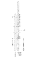
図1は、本実施形態で用いた電子写真プロセスを利用した、Y、M、C、Bkの4色のカラー画像形成装置の一例を示す概略断面図である。尚、以下では、4色のカラー画像形成装置について説明を行うが、勿論、6色等のカラー画像形成装置に本願を適用できることはいうまでもない。
[Schematic sectional view of image forming apparatus: FIG. 1]
FIG. 1 is a schematic cross-sectional view showing an example of a color image forming apparatus for four colors Y, M, C, and Bk using the electrophotographic process used in the present embodiment. In the following description, a four-color image forming apparatus will be described, but it goes without saying that the present application can be applied to a six-color image forming apparatus.
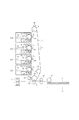
図1の説明に戻ると、本装置は、装置本体に対して着脱可能なプロセスカートリッジ32を縦方向に並置する構成となっている。図1中において、数字の後に付加されたa、b、c、dの符号は各色に対応しており、以下では、このa、b、c、dを区別することなく説明を行なっていく。プロセスカートリッジ32はY、M、C、Bk用の感光ドラム2、感光ドラム2にそれぞれのトナーを現像する現像器、感光ドラム2上の残余トナーを除去するクリーニング部を有する。そして、これらプロセスカートリッジ(画像形成ステーション)32で形成したそれぞれ色の異なるトナー像を、像担持体としての中間転写ベルト31に順次に重ねて転写した後、それを転写材Sに一括転写することでフルカラー画像を得る構成となっている。転写材Sは、給紙ユニット15から給紙され、排紙トレイ(不図示)に排出される。
Returning to the description of FIG. 1, the present apparatus is configured such that process cartridges 32 detachable from the apparatus main body are juxtaposed in the vertical direction. In FIG. 1, the symbols a, b, c, and d added after the numbers correspond to the respective colors, and the following description will be made without distinguishing between a, b, c, and d. The process cartridge 32 has a
感光ドラム2は、繰り返し使用される回転ドラム型の電子写真感光体であり、予め決められた周速度(プロセススピード)をもって回転駆動される。この感光ドラム2は、1次帯電ローラ(帯電手段)3により予め決められた極性・電位(本実施の形態ではマイナス)に一様に帯電処理されている。そして、画像露光手段4(レーザダイオード、ポリゴンスキャナ、レンズ群、等によって構成される)による画像露光を受けることにより、第1〜第4の色成分像(例えば、イエロー、マゼンタ、シアン、ブラック成分像)に対応した静電潜像が形成される。
The
次いで、現像器により、像担持体に形成された静電潜像へ現像剤としてのトナーを付着させる、いわゆる現像が行われる。現像器は、トナーを収容するトナー容器と、トナーを担持し搬送する現像剤担持体としての現像ローラ(現像手段)5からなる。現像ローラ5は、抵抗調整された弾性ゴムで構成されている。現像ローラ5は感光ドラムに対して順方向に回転しながら、感光ドラム2に対して接触配設されている。現像ローラ5に予め決められた極性の高圧(本実施の形態ではマイナス)を印加することで、各現像器内で同一極性に摩擦帯電された状態で現像ローラ5上に担持されているトナーが、感光ドラム2上の静電潜像に転移することで現像が行われる。
Next, the developing device performs so-called development in which toner as a developer is attached to the electrostatic latent image formed on the image carrier. The developing device includes a toner container for containing toner and a developing roller (developing means) 5 as a developer carrying member for carrying and transporting the toner. The developing roller 5 is made of elastic rubber whose resistance is adjusted. The developing roller 5 is disposed in contact with the
中間転写ベルト31(像担持体)は、各感光ドラム2と接触しながら、感光ドラム2とほぼ同じ周速度をもって、駆動ローラ8の作用で回転駆動されている。また、中間転写ベルト31は、108〜1012Ωcmの体積固有抵抗率を持たせた厚さ50〜150μm程度の無端のフィルム状部材で構成されている。さらに、中間転写ベルト31は黒色で反射率の大きなものとした。そして中間転写ベルト31を挟んで、感光ドラム2の対向に配置された一次転写ローラ(1次転写手段)14に印加した高圧による静電気の作用で、感光ドラム2から異なる各色のトナー像が中間転写ベルト31に転写される。一次転写ローラ14は、107〜109Ωに抵抗調整されたソリッドゴムローラである。そして、感光ドラム2から中間転写ベルト31にトナー像の転写が行われた後の感光ドラム2上に残留する一次転写残トナーは、クリーニングブレード6によって除去回収される。
The intermediate transfer belt 31 (image carrier) is rotationally driven by the action of the driving roller 8 at substantially the same peripheral speed as that of the
給紙ユニット15から給紙された転写材Sは、予め決められたタイミングにて駆動回転するレジストローラ対17によって、中間転写ベルト31と二次転写ローラ35のニップ部に向けて給送される。続いて、二次転写ローラ35に印加した高圧による静電気の作用で、中間転写ベルト31上のトナー画像が転写材Sに転写される。二次転写ローラ35は、107〜109Ωに抵抗調整されたソリッドゴムローラである。そして、フルカラートナー像が定着器18による加熱加圧によって、トナーが転写材Sに定着され、機外(画像形成装置本体外部)に排出される。中間転写ベルト31から転写材Sにトナー像の転写が行われた後の中間転写ベルト31上に残留する二次転写残トナーは、クリーニング手段としてのクリーニングブレード33によって除去回収される。
The transfer material S fed from the
[画像形成装置のブロック図:図2]
図2に、本画像形成装置の制御部構成の一例を示すブロック図である。
[Block diagram of image forming apparatus: FIG. 2]
FIG. 2 is a block diagram illustrating an example of the configuration of the control unit of the image forming apparatus.
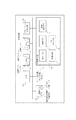
CPU101は、ROM102に格納された各種制御プログラムに基づいてRAM103を作業領域に用い画像形成装置の各部を制御しながら、環境の変化に起因する画像の色味変動を低減し、色味を安定させる為の画像濃度制御処理を行なう。また、精度よくカラー画像を形成するために各色の画像を形成するタイミングを調整する色ずれ補正制御処理など行なう。また、後述の各フローチャートにおける各ステップの処理に係る演算、指示、各部材の制御、センサーからのデータの取り込み処理も行なう。環境の変化とは、例えば、(1)消耗品の交換、(2)使用する環境の変化(温度、湿度、装置の劣化)、(3)消耗品の使用状況変化(プリント枚数)等である。ROM102には、各種制御プログラムや各種データ、テーブルが格納されている。RAM103にはプログラムロード領域、CPU101の作業領域、各種データの格納領域などがある。104はパッチ或いはライン状のトナー像を発生するテストパターン発生手段である。106は中間転写ベルト31上に形成された濃度調整用パッチや光量調整用パッチ(光量調整用画像とも呼ぶ)などのトナー画像(パッチ)を検出する光学検知センサ40等を含むトナー付着量&色ずれ量検出部である。画像形成部108には、上記説明した感光ドラム2、帯電手段3、画像露光手段4、現像手段5、1次転写手段14等などが含まれる。各種データを保存する109は不揮発メモリであり、画像濃度制御実行時の光量設定等が格納されている。この画像濃度制御実行時の光量設定は、後述の図14のフローチャートの実行により、図7のフローチャートが実行される前に先立って、不揮発性メモリに格納される。図14のフローチャートが未実行の場合には、初期値が格納されているものとする。
The
尚、上の例では、CPU101の処理に基づき、各種処理が行なわれるよう説明してきたが、CPU101が行なう処理の一部或いは全てを集積回路であるASICに行なわせても良い。また、その逆で処理を行っても良い。
In the above example, it has been described that various processes are performed based on the process of the
[光学検知センサ:図3]
次に、光学検出部106の詳細について図3を用いて説明する。
[Optical detection sensor: Fig. 3]
Next, details of the optical detection unit 106 will be described with reference to FIG.
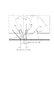
図1に示すように本画像形成装置には、中間転写ベルト31の対向部に光学検知手段としての光学検知センサ40が配置されている。光学検知手段としての光学検知センサ40は、図3に示すように波長950nmのLED発光素子40a、フォトダイオード等のふたつの受光素子40b、40c及びホルダーから構成されている。そして、発光素子40aからの赤外光を中間転写ベルト31自体や、中間転写ベルト31上の各色のパッチや、ライン(位置検知用画像)に照射させ、反射光を受光素子40b、40cで測定する。この測定により中間転写ベルト31の状態や、トナー付着量や、トナー位置ずれ量(色ずれ量)を演算することが出来る。また、光学検知センサ40は、発光素子40aが照射角度15°、受光素子40bが受光角度15°、受光素子40cが受光角度45°に設定されている。ここで、パッチやラインからの反射光には正反射成分と乱反射成分が含まれているが、40bでは、正反射成分と乱反射成分の両方を検出し、40cは、乱反射成分のみを検出する構成となっている。
As shown in FIG. 1, in the image forming apparatus, an
図4で示すように、中間転写ベルト31上にトナーが付着すると、トナーによって光が遮断されるため、正反射光は減少する、即ち、受光素子40bの出力は低下する。一方、本実施形態で使用した950nmの赤外光に対して、黒トナーは吸収し、イエロー、マゼンタ、シアントナーは乱反射する為、中間転写ベルト31上のトナー付着量が増大すると、イエロー、マゼンタ、シアンに関しては、受光素子40cの出力が大きくなる。尚、受光素子40bもその影響を受ける。即ち、イエロー、マゼンタ、シアンに関しては、トナー付着量が多く、トナーで中間転写ベルト31を完全に遮断しても、その出力はゼロにはならない。また、受光素子40bに関しては、乱反射成分の影響をできるだけ小さくするため、受光素子40cより、アパーチャ径を小さくしてある。ここで光学検知センサ40のアパーチャ径は、発光素子40a 0.7mm、受光素子40b 1.5mm、受光素子40c 2.9mmとした。また、受光素子40bによる正反射光成分の検出範囲としてはφ1.0mm程度であり、受光素子40cによる乱反射光成分の検出範囲は、発光素子40aによる照射の拡がりに相当し、φ3.0mm程度となっている。以下、これらのことを、受光素子40bのスポット径、受光素子40cのスポット径と呼ぶ。
As shown in FIG. 4, when toner adheres to the
[画像濃度制御の必要性]
次に、本実施形態における画像濃度制御に関して説明する。
[Necessity of image density control]
Next, image density control in the present embodiment will be described.
一般に、電子写真方式のカラー画像形成装置では、(1)消耗品の交換、(2)使用する環境の変化(温度、湿度、装置の劣化など)、(3)消耗品の使用状況変化(プリント枚数)等の諸条件によって、トナーや上述した各キーパーツの特性が変化する。その特性の変化は、画像濃度の変動、色再現性の変化として顕在化する。即ち、この変動により、本来の正しい色再現性が得られなくなってしまう。そこで、本実施形態では、常に正確な色再現性が得られるようにする為、ユーザの指示に基づく画像形成を行っていない状態で、作像条件を変えながら、複数のパッチ(濃度検知用画像)を試験的に形成し、それらの濃度を光学検知センサ40で検知する。そして、その検知結果を基に、画像濃度に影響を与える因子を制御する濃度検知手段としての画像濃度制御を実行する。この画像濃度制御とは、画像濃度に影響を与える因子を変更し、画像形成条件の調整又は更新することを意味する。そして、画像濃度に影響を与える因子としては、帯電バイアス、現像バイアス、露光強度、ルックアップテーブル等を代表例として挙げることができる。以下では、画像濃度制御として、ルックアップテーブル(後述の図12、13)を更新/調整する例を説明することとする。しかし、画像濃度制御としては、ルックアップテーブルの制御のみに限定されることはなく、上に代表例を挙げた、帯電バイアス、現像バイアス、露光強度等を調整/更新することもできる。尚、画像濃度制御の具体的な動作については後述の図7で詳しく説明する。
In general, in an electrophotographic color image forming apparatus, (1) replacement of consumables, (2) changes in the environment used (temperature, humidity, deterioration of the device, etc.), and (3) changes in the usage status of consumables (printing) The characteristics of the toner and the key parts described above vary depending on various conditions such as the number of sheets. The change in the characteristics is manifested as a change in image density and a change in color reproducibility. That is, due to this variation, the original correct color reproducibility cannot be obtained. Therefore, in this embodiment, in order to obtain accurate color reproducibility at all times, a plurality of patches (density detection images) can be obtained while changing image forming conditions in a state where image formation based on a user instruction is not performed. ) Are formed on a trial basis, and their density is detected by the
[画像濃度制御のための光量調整の必要性]
次に、本実施形態における画像濃度制御に先立って行う光量調整手段としての光量調整に関して説明する。
[Necessity of light intensity adjustment for image density control]
Next, the light amount adjustment as the light amount adjusting means performed prior to the image density control in the present embodiment will be described.
図4のように、受光素子40b、40cの出力とトナー付着量に相関関係を見ることができる。一方、発光光量が多過ぎると、図5のように、トナー付着量が少ない領域において、受光素子40bの出力が上限に張り付いてしまったり、トナー付着量が多い領域において、受光素子40cの出力が上限に張り付いてしまったりしている。この状態では正確なトナー付着量の演算が行えない。また、図6のように、発光光量が少な過ぎると、トナー付着量の変化に対して、受光素子40b、40cの出力変化が小さくなり、トナー付着量換算した場合に誤差が大きくなってしまう。
As shown in FIG. 4, the correlation between the output of the
即ち、画像濃度制御を正確に行うためには、図4のように、受光素子40b、40cの両方とも、その出力が上限に張り付くことなく、トナー付着量の変化に対して、大きな検出レンジを得られるような発光素子の光量を選択することが重要である。ところが、受光素子の出力は、検出対象面である中間転写ベルト31表面の経時による色味変化、光学検知センサの経時汚れ、光学検知センサの各構成部品のロットバラツキ等により変化する。この為、画像濃度制御で用いる発光素子の適切光量設定を随時見直すための校正(光量調整)を定期的に行うことが必要となる。尚、光量調整の具体的な動作については後述する。
That is, in order to accurately control the image density, as shown in FIG. 4, both the
[色ずれ補正制御(位置ずれ補正制御)の必要性]
先に説明したように、電子写真方式のカラー画像形成装置では、(1)消耗品の交換、(2)使用する環境の変化(温度、湿度、装置の劣化など)、(3)プリント枚数等の諸条件によって、上述した各パーツの特性が変化する。そして、駆動ローラ8の耐久磨耗、温湿度による伸縮、画像露光手段4による感光ドラム2へのレーザー照射位置変動等の特性の変化は、カラー画像を形成した際に、各色のトナーが正確に重なり合わなくなる色味変動として顕在化する。
[Necessity of color shift correction control (position shift correction control)]
As described above, in an electrophotographic color image forming apparatus, (1) replacement of consumables, (2) change in environment (temperature, humidity, deterioration of the apparatus, etc.), (3) number of prints, etc. Depending on these conditions, the characteristics of each part described above change. Changes in characteristics such as durable wear of the driving roller 8, expansion and contraction due to temperature and humidity, and fluctuation of the laser irradiation position on the
そこで、常に正確な色再現性を得る為、本実施形態では、ユーザ指示による画像形成を行っていない状態で、複数色のライン画像を試験的に形成し、光学検知センサ40で検知する。そして、その検知結果を基に、色毎に、画像を形成するタイミング(主走査方向、副走査方向)を調整する色ずれ調整制御を実行する。尚、色ずれ補正制御の具体的な動作については後述する。
Therefore, in order to always obtain accurate color reproducibility, in the present embodiment, a line image of a plurality of colors is formed on a trial basis and is detected by the
このように、本実施形態のカラー画像形成装置は、今述べた色ずれ制御用のパッチ(ライン)、また、先に説明した濃度制御用パッチ、濃度制御時の光量調整用パッチの少なくとも3種類のパッチを形成する。そして、これらのことを、夫々、第1検知用画像(第1検出用画像)、第2検知用画像(第2検出用画像)、第3検知用画像(第3検出用画像)などと区別して呼ぶこともある。 As described above, the color image forming apparatus according to this embodiment includes at least three types of patches (lines) for color misregistration described above, a density control patch described above, and a light amount adjustment patch for density control. Form a patch. These are separated from the first detection image (first detection image), the second detection image (second detection image), the third detection image (third detection image), and the like. Sometimes called separately.
[画像濃度制御の具体例]
次に本実施形態における画像濃度制御の具体例について図7、図8を用いて説明する。まずステップS1で、画像濃度制御が起動されると、中間転写ベルト31の回転動作を開始する。またそれと共に、ステップS2で、不揮発性メモリ109(不揮発性記憶手段109)に格納された画像濃度制御実行時の光量設定を読込み、光学検知センサ40を発光させる。このステップS2の処理により、画像濃度制御の中で行っていた光量調整とそれに付随して発生していたクリーニング動作の時間を削除でき、結果、画像濃度制御の時間の短縮を実現することができる。
[Specific example of image density control]
Next, a specific example of image density control in this embodiment will be described with reference to FIGS. First, when image density control is activated in step S1, the rotation operation of the
次にステップS3で、中間転写ベルト31を2周させ、中間転写ベルト31上に付着したトナーを、クリーニングブレード33の作用で、除去する。
Next, in step S <b> 3, the
次に、ステップS4で光学検知センサ40の発光が安定した所で、ステップS5で、中間転写ベルト31自体からの受光素子40b、40cそれぞれの反射光信号Bb,Bcの取得を開始する。その後、中間転写ベルト31がさらに1周回転した所で、図8の804下部に示したような色毎のパッチ画像を形成する。図8の804の下部のY、M、C、Kのパッチは、中間転写ベルト31の2周目で形成及び検知されるパッチである。
Next, when the light emission of the
そしてステップS6で、パッチ画像の中央部において、受光素子40b、40cそれぞれの反射光信号Pb、Pcの取得を行う。この際、ステップS5、S6過程では、中間転写ベルト31上の同一/略同一箇所での信号を取得するように制御する。なお、パッチ画像の中央部とは、図8の下部に示される個々の正方形のパッチの中央を指す。
In step S6, the reflected light signals Pb and Pc of the
尚、本実施形態では、パッチ画像全体が中間転写ベルト31の周長以内に収めるようにしている。これは、パッチ画像全体の長さが、中間転写ベルト31の形成が一周長以上になり、一周分のパッチ形成を終えた後に、クリーニング動作などが入り、処理時間を長く要することを防止する為である。
In the present embodiment, the entire patch image is set within the circumference of the
そして、ステップS11で、ステップS6での受光素子40b、40cによる反射光信号Pb、Pcの取得を完了すると、光学検知センサ40の発光素子40aを消灯させる。
In step S11, when the acquisition of the reflected light signals Pb and Pc by the
また、ステップS7で、各パッチに関して、ステップS5,S6の結果を基に、トナー付着相当量を換算する。換算方法は、種々のものが考えられる。例えば、Bb,Bc,Pb,Pcを用いて、以下のような式で演算することが可能である。
トナー付着相当量={Pb−α*(Pc−Bc)}/Bb ・・・数式1
ここで、αは定数であり、RAM103あるいは不揮発メモリ109に格納してあるもの(画像形成装置の所定の動作により演算)を使用したり、予めROM102に格納されてあるものを用いたりする。このトナー付着相当量は、値が小さくなるほど、実際にはトナー付着量が多くなる。この数式の分子は、パッチ画像に光を照射した際の受光素子40bによって受光される正味の正反射光(乱反射成分を差し引く)を意味していることになる。
In step S7, for each patch, the toner adhesion equivalent amount is converted based on the results of steps S5 and S6. Various conversion methods are conceivable. For example, using Bb, Bc, Pb, Pc, it is possible to calculate with the following formula.
Toner adhesion equivalent amount = {Pb−α * (Pc−Bc)} /
Here, α is a constant, and one stored in the
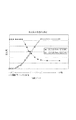
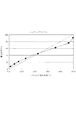
さらに、このトナー付着相当量は、ROM102に内蔵してある図9で示したようなテーブルを用いて、トナー付着量や実際に紙へ印字した際の画像濃度に換算することが可能となる。紙上濃度への換算は、パッチとして用いたハーフトーン画像を、キヤノンCLC−Sk(坪量80g)の用紙に印字し、それをGretag Macbeth社製のRD918にて測定した結果との相関を取ったものである。 Further, the toner adhesion equivalent amount can be converted into the toner adhesion amount and the image density when actually printed on paper by using a table as shown in FIG. The conversion to the density on paper was correlated with the result of printing the halftone image used as a patch on Canon CLC-Sk (basis weight 80 g) paper and measuring it with RD918 manufactured by Gretag Macbeth. Is.
その後、ステップS8で、トナー付着量あるいは画像濃度への換算結果を基に、ルックアップテーブルの更新を行う。さらに、ステップS6の処理終了後、ステップS7、S8と並行して、ステップS9で、中間転写ベルト31上に形成した画像のクリーニング(中間転写ベルト31を2周)を行う。そして、クリーニングが終了した時点で、ステップS10で、中間転写ベルト31の回転を停止し、画像濃度制御は完了となる。
Thereafter, in step S8, the look-up table is updated based on the result of conversion into the toner adhesion amount or the image density. Further, after the processing in step S6 is completed, in parallel with steps S7 and S8, in step S9, the image formed on the
[画像濃度制御の詳細]
以下、図10乃至12を用いて、図7のステップS8の処理の詳細の一例について説明する。まず、パッチ画像のサイズであるが8mmX8mmの複数のハーフトーンパターンを用いた。上述した受光素子40cのスポット径がφ3.0mmであること、パッチエッジ部ではトナー載り量が不均一になる傾向があること、パッチ中央部で複数回のサンプリングを行うことを鑑み、パッチサイズを決定している。これらは、実際の画像形成に用いる多値ディザ処理を施したパターンであり、画像露光手段4による露光比率が6%、13%、21%、31%、43%、61%、75%、90%の8個のハーフトーン画像をパッチとして用いた。尚、ルックアップテーブルの更新の概略は以下の通りである。
[Details of image density control]
Hereinafter, an example of details of the processing in step S8 in FIG. 7 will be described with reference to FIGS. First, a plurality of halftone patterns of 8 mm × 8 mm as the size of the patch image were used. In view of the fact that the spot diameter of the
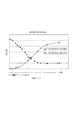
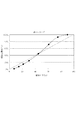
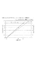
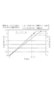
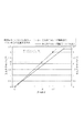
図10の横軸は、露光比率であり階調に相当し、縦軸は紙に印刷した際の画像濃度である。また、図11は、図10により概算される最大濃度(露光時間100%時の濃度)で規格化し、各ポイントを線形補間したものである。この曲線のことを「素のγカーブ」と呼ぶ。そして、この「素のγカーブ」の縦軸と横軸を入れ替えたテーブルがルックアップテーブル(図12)である。ホストからの入力画像データをルックアップテーブルで変換して実際の画像形成を行うことで、ホストによる画像濃度指示と実際の濃度の間に、線形の関係(図13)が生まれ、正確な色再現を行うことができるようになる。 The horizontal axis in FIG. 10 is the exposure ratio and corresponds to the gradation, and the vertical axis is the image density when printed on paper. FIG. 11 is a graph obtained by normalizing the maximum density (density at an exposure time of 100%) estimated by FIG. 10 and linearly interpolating each point. This curve is called a “primary γ curve”. A table in which the vertical axis and the horizontal axis of the “primary γ curve” are exchanged is a lookup table (FIG. 12). By converting the input image data from the host using a lookup table and performing actual image formation, a linear relationship (FIG. 13) is created between the image density instruction from the host and the actual density, and accurate color reproduction is achieved. Will be able to do.
[色ずれ補正制御&画像濃度制御時の光量調整]
次に、本実施形態における色ずれ補正制御及び画像濃度制御時の光量調整の処理について、図14、図15を用いて説明する。尚、本実施形態では、受光素子40bの出力に基づいて、色ずれ補正制御を実施する場合について説明する。
[Light intensity adjustment during color shift correction control & image density control]
Next, light amount adjustment processing during color misregistration correction control and image density control in the present embodiment will be described with reference to FIGS. 14 and 15. In the present embodiment, a case where color misregistration correction control is performed based on the output of the light receiving element 40b will be described.
ステップS21で、色ずれ補正制御が起動されると、中間転写ベルト31の回転動作を開始する。
In step S21, when the color misregistration correction control is activated, the rotation operation of the
次に、ステップS22で、色ずれ補正制御用発光光量の設定及び、設定された色ずれ補正制御用の光量で光学検知センサ40を発光させる。一般的に、色ずれ補正制御用の光量設定に対する精度の許容範囲は、画像濃度制御における光量設定に比べて大きい。上述の通り、色ずれ補正制御はライン画像のエッジ部変化が読み取れればよいからである。そこで、色ずれ補正制御用の光量を決定する為の動作としては、例えば、色ずれ補正制御に先立ち、光量の設定値をいくつか割り振って、中間転写ベルト31自体を照射し、受光素子40bの出力が、所定範囲となるような光量の設定値を選択する。この場合、画像濃度制御のように調整用パッチを形成する場合に比べ、時間短縮を実現できる。
Next, in step S22, the
次に、ステップS23で、中間転写ベルト31を2周させ、中間転写ベルト31上に付着(残留)した残トナーを、クリーニングブレード33の作用で除去する。
Next, in step S <b> 23, the
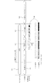
次に、ステップS24で、光学検知センサ40の発光が安定した所で、ステップS25で、色ずれ検知用のパターンとして、図15に示したような主走査方向の長さが2mmである、色ずれ補正制御用の斜めライン画像を中間転写ベルト31上に形成する。図15の1503の下部に示されたパッチがそれに相当する。また、この時に、光量調整用パッチも、中間転写ベルト31の1周以内に形成する。図15の1504の下部に示される正方形の4つのパッチがそれに相当する。ここで、光量調整用パッチは、画像濃度制御で用いたパッチと同サイズの8mmX8mmのベタ画像であり、各色で合計4個ある。従って、光量調整用パッチを検出するのに時間をあまり要せず、色ずれ補正制御の時間を大幅に伸ばしてしまうことは無い。また、図15中では、光量調整用パッチが斜めライン画像の後に形成されているが、斜めライン画像の前に形成しても良い。
Next, in step S24, where the light emission of the
次に、ステップS26で、受光素子40bの出力変動を基に、それぞれのライン画像位置の特定を行う。より具体的には、同一のライン画像をベルト搬送方向軸に対して45°と−45°の線により配置することで、ライン画像の主走査方向ずれ量、副走査方向ずれ量の特定を行う。尚、上述した色ずれ補正制御で使用する受光素子40bのスポット径はφ1.0mmであること、ライン画像のエッジ部での出力変化が取得できれば良いことを鑑み、ライン画像の主走査方向の長さ設定を行っている。尚、検出された主走査方向ずれ量及び副走査方向ずれ量を基に、具体的にどのように色ずれ補正を行なうかについては、色毎に、画像を形成するタイミング(主走査方向、副走査方向)を調整する等が従来から知られており、詳しい説明はここでは省略する。また、求められた各色のずれ量から、レーザダイオードの発光タイミングを変更する等の画像形成条件を変更するなども既に良く知られた技術なので詳しい説明を省略する。 Next, in step S26, each line image position is specified based on the output fluctuation of the light receiving element 40b. More specifically, the same line image is arranged by 45 ° and −45 ° lines with respect to the belt conveyance direction axis, thereby specifying the amount of deviation of the line image in the main scanning direction and the amount of deviation in the sub scanning direction. . In view of the fact that the spot diameter of the light receiving element 40b used in the color misregistration correction control described above is φ1.0 mm and that it is sufficient to obtain the output change at the edge portion of the line image, the length of the line image in the main scanning direction is sufficient. The setting is done. Note that, based on the detected amount of deviation in the main scanning direction and the amount of deviation in the sub-scanning direction, the color misregistration correction is specifically described with respect to the timing of image formation for each color (main scanning direction, sub-scanning direction). The adjustment of the scanning direction is conventionally known, and detailed description thereof is omitted here. Further, since it is a well-known technique to change the image forming conditions such as changing the light emission timing of the laser diode from the obtained shift amount of each color, detailed description is omitted.
次に、ステップS27で、色ずれ検知用の斜めライン画像に引き続いて、画像濃度制御用の光量を決定する為の光量調整用パッチについて、パッチの中央部からの反射光に対応する受光素子40cの出力を取得する。取得方法は、画像濃度制御におけるそれと同様である。また、ステップS27では、受光素子40cの出力に基づき、濃度検知時における光量設定を行う。ここで、光量調整用パッチへの発光に際して、光量設定を変化させた場合、出力が安定するまでに時間を長く必要とする。しかし、これでは、光量調整用パッチを色ずれ検知用の画像に引き続き連続して読み込むことができない。これに対して、ステップS27では、光量調整用パッチ出力の取得に際して、色ずれ補正制御用の光量設定と同じ或いは略同じで光学検知センサ40を発光する。なお、濃度制御用の光量設定については、実際には濃度制御時までに行えば良く、ステップS27のタイミングに限定されるものではない。
Next, in step S27, the
次に、ステップS30で、受光素子40cによる光量調整用パッチの出力の取得完了後、光学検知センサ40の発光素子40aを消灯させる。またステップS30の処理とともに、ステップS28で、中間転写ベルト31上に形成した画像をクリーニングするために、中間転写ベルト31を2周させ、ステップS29で、中間転写ベルト31の回転を停止する。これで、色ずれ補正制御&画像濃度制御の光量調整は終了となる。
Next, in step S30, after completing the acquisition of the light amount adjustment patch output by the
[画像濃度制御用の光量決定方法]
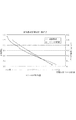
以下、図16を用いて、濃度制御用の光量調整に係る詳細について説明する。尚、図16では、ベタ画像と中間転写ベルト31夫々に関する発光光量−受光素子出力特性について、ベタ画像のそれのほうが大きい場合に対応する。これは後述する図21の中間転写ベルト31をある程度使用した場合に対応するともいえる。尚、受光素子出力特性とは、ある大きさの光を照射した場合に、受光素子がどれくらいの光を検知し、その検知に対応した出力を行なうかというものであり、発光光量−検知出力特性などと呼ぶこともある。尚、中間転写ベルト31に関する発光光量−受光素子出力特性がグラフ中にあるのは、濃度検出を行なう上で、中間転写ベルト31の下地濃度特性を計測する必要があり、その中間転写ベルト31の検知結果も、正常範囲内に収める必要があるからである。グラフ中の線は、(IO、0)と、(IR、Sc)の2点を直線で結ぶことで作成されたものである。
[Light intensity determination method for image density control]
Hereinafter, the details relating to the light amount adjustment for density control will be described with reference to FIG. Note that FIG. 16 corresponds to a case where the solid light image and the light receiving element output characteristics of the solid image and the
所定値I0は、受光素子の特性により予め定まったものであり、検知可能な最小の光量を意味する。言い換えれば、I0以上の光量に設定することで発光素子40aによる発光が開始される。また、I0は予め決まった値なので、予め不揮発メモリ109に格納されているものとする。なお、当該格納は、CPU101の格納制御により行なわれるものとする。
The predetermined value I0 is determined in advance by the characteristics of the light receiving element, and means the minimum detectable light amount. In other words, the light emission by the light emitting element 40a is started by setting the light amount to I0 or more. Since I0 is a predetermined value, it is assumed that it is stored in advance in the
またIRは、上述の光量調整用パッチを検出する際に使用した色ずれ補正用の光量設定である。このIRは、ステップS22で決定された色ずれ補正制御用発光光量に相当する。 IR is a light amount setting for color misregistration correction used when the above-described light amount adjustment patch is detected. This IR corresponds to the light emission amount for color misregistration correction control determined in step S22.
また、4つの光量調整用パッチ(イエロー、マゼンタ、シアン、ブラック)を受光素子40cで検出した時の最大値をScとする。例えばイエロー、マゼンダ、シアン、ブラックのうち、受光素子40cの出力値が、マゼンダが最大であれば、そのマゼンダの出力値が、図16中のScとし設定される。また、ターゲットラインをSt(固定値)とする。ターゲットラインStは、予め受光素子の特性より仕様として決まっており、ROM102等に事前に記憶され、CPU101がROM102から必要な時に読込み特定される。
The maximum value when four light intensity adjustment patches (yellow, magenta, cyan, and black) are detected by the
ここで、光量設定が大き過ぎると、受光素子40c、受光素子40bの出力が上限に張り付いてしまう。受光素子40cの検出レンジをなるべく大きくしつつ、上限に張り付かないような値(図16のターゲットライン)に設定するのが、もっとも好ましい。
Here, if the light amount setting is too large, the outputs of the
そして、この好ましい形態を実現すべく、画像濃度制御用の光量設定IDは、以下のようにして演算される。
ID = (St/Sc)*(IR−I0)+I0 ・・・数式2
そして、演算された画像濃度制御用の光量設定IDを不揮発メモリ109に格納し更新する。尚、この不揮発性メモリ109に記憶された光量設定IDは、図7のS2で、不揮発性メモリ109から読込まれる値に相当する。また、光量を設定できる値であれば、光量そのものの値でも良いし、或いは、間接的に光量を設定できる値であっても良い。
In order to realize this preferable mode, the light amount setting ID for image density control is calculated as follows.
ID = (St / Sc) * (IR−I0) +
Then, the calculated light amount setting ID for image density control is stored in the
[反射光の種類と色ずれ補正制御用パッチの長さの関係]
図17(a)は、本実施形態の一効果を説明する為の表である。縦軸には、受光素子で受光する光の種類を、横軸には各種処理の対応関係を示している。
[Relationship between reflected light type and color misregistration correction patch length]
FIG. 17A is a table for explaining one effect of the present embodiment. The vertical axis indicates the type of light received by the light receiving element, and the horizontal axis indicates the correspondence between various processes.
図17(a)には、画像濃度制御において、正反射光、乱反射光(拡散反射光)の双方を用いることが示されている。先にも述べたように、乱反射成分を差し引いた正反射出力を利用するのが濃度検知用画像の検出で一般的である。これまで述べてきた通り、例えば本実施例で示した光学検知センサ40では、受光素子40bで取得される反射光量には、正反射光成分のみならず、一部乱反射成分を含んでいる。この乱反射成分を差し引き、正味の正反射光に基づいて制御することで、画像濃度制御の精度を確保することが可能となるからである。
FIG. 17A shows that both regular reflection light and irregular reflection light (diffuse reflection light) are used in image density control. As described above, it is common to detect the density detection image that uses the regular reflection output obtained by subtracting the irregular reflection component. As described so far, for example, in the
また、色ずれ補正制御については、どのような状態/種類の像担持体に、色ずれ補正制御用のパッチを形成するかによって、パッチの検知にどのような種類の光を用いるかが変わってくることが示されている。まず、安価な像担持体では、色ずれ補正制御用のパッチの検知に乱反射が適することが示されている。これは、安価な像担持体は高価な場合に対して表面の凹凸が激しくなり、像担持体表面の光沢度が低下することで、像担持体表面からの正反射光成分が少なくなり、色ずれ補正制御の精度を確保する為の反射光が確保できなくなることを踏まえている。これに対し、乱反射であれば、スポット径が大きく、反射光も多いため、像担持体の表面の凹凸影響割合が少なく、より高精度な検知を行なえる。一方、高価な像担持体上に色ずれ補正制御用のパッチを形成する場合には、安価な像担持体の場合と比べて、表面の凹凸が少なく、正反射光による検出を行なっても、像担持体表面の凹凸の影響を心配する必要が少ない。この安価な像担持体と高価な像担持体とを採用した夫々の場合において、色ずれ補正制御用パッチの長さに差異が出てくる。安価な像担持体の場合には、乱反射光が適しているので、スポット径が大きく、その結果、色ずれ補正制御用パッチの長さが長くなる。一方、高価な像担持体の場合には、正反射光用いることができ、この場合、図3に示した通り、乱反射光を用いる場合に比べて、スポット径を小さく出来、その結果、色ずれ補正制御用パッチの長さを短くすることができる。 Regarding color misregistration correction control, the type of light used for patch detection varies depending on the state / type of image carrier on which the color misregistration correction control patch is formed. Shown to come. First, it has been shown that an inexpensive image carrier is suitable for irregular reflection for detecting a patch for color misregistration correction control. This is because an inexpensive image carrier has a rough surface as compared with an expensive image carrier, and the glossiness of the surface of the image carrier is reduced, so that the component of specular reflection light from the surface of the image carrier is reduced. It is based on the fact that reflected light for ensuring the accuracy of deviation correction control cannot be secured. On the other hand, in the case of irregular reflection, since the spot diameter is large and the amount of reflected light is large, the ratio of unevenness on the surface of the image carrier is small, and more accurate detection can be performed. On the other hand, when forming a patch for color misregistration correction control on an expensive image carrier, there are fewer surface irregularities than in the case of an inexpensive image carrier, and even if detection by specular reflection light is performed, There is little need to worry about the effects of irregularities on the surface of the image carrier. In each case where the inexpensive image carrier and the expensive image carrier are employed, there is a difference in the length of the color misregistration correction control patch. In the case of an inexpensive image carrier, irregularly reflected light is suitable, so that the spot diameter is large, and as a result, the length of the color misregistration correction control patch becomes long. On the other hand, in the case of an expensive image carrier, specular reflection light can be used. In this case, as shown in FIG. The length of the correction control patch can be shortened.
本実施形態では、色ずれ補正制御用パッチの検出に、正反射光を用いており、結果、図17(b)に示すように、色ずれ補正制御用パッチの副走査方向の長さを短くできる。その結果、色ずれ補正制御用パッチを像担持体1周分に多数形成することができ、色ずれ補正制御の精度を一定のレベルに維持することが出来る。また、画像濃度制御用の光量調整のため、光量調整用パッチが4色分続いているが、この長さを考慮しても、乱反射光を色ずれ補正制御用パッチに用いた場合に比べ、パターンの全長を短くすることができる。例えば像担持体の1周の長さを600mmとすれば、光量調整用パッチにより、色ずれ補正制御用パッチの精度にはさほど影響しない。 In the present embodiment, regular reflection light is used for detecting the color misregistration correction control patch. As a result, as shown in FIG. 17B, the length of the color misregistration correction control patch in the sub-scanning direction is shortened. it can. As a result, a large number of color misregistration correction control patches can be formed for one rotation of the image carrier, and the accuracy of color misregistration correction control can be maintained at a certain level. Also, the light intensity adjustment patch continues for four colors for light intensity adjustment for image density control, but even if this length is taken into consideration, compared with the case where irregularly reflected light is used for the color misregistration correction control patch, The total length of the pattern can be shortened. For example, if the length of one circumference of the image carrier is 600 mm, the accuracy of the color misregistration correction control patch is not significantly affected by the light amount adjustment patch.
一方、色ずれ補正制御用パッチを用いて光量調整を行なうことも考えられるが、その場合には、以下の問題を発生してしまう。光量調整は、ベタ画像のため、乱反射光の検出量のほうが一般的に大きく(図4を参照)、その乱反射光で検出を行なう必要がある。すると、色ずれ補正制御用のパッチも乱反射光で検出する必要があり、乱反射光のスポット径が大きいため、色ずれ補正制御用パッチの副走査方向幅を太くする必要がある(例えば図17(b)中の光量調整用パッチと同じ8mm)。その結果、像担持体1周以内に形成できる色ずれ補正制御用パッチの数が少なくなり、色ずれ補正制御の精度を低下させてしまう。また、色ずれ補正制御の為に一部のパッチの副走査方向幅を太くすることも一見して想定されるかもしれない。しかしながら、色ずれ補正制御用パッチの間隔は一定間隔でなければ、像担持体上のムラを偏って検知してしまう可能性が高くなり、実際には、そのような形態は現実的ではない。 On the other hand, it is conceivable to adjust the light amount by using a color misregistration correction control patch, but in this case, the following problems occur. Since the light amount adjustment is a solid image, the detected amount of the irregularly reflected light is generally larger (see FIG. 4), and it is necessary to perform detection with the irregularly reflected light. Then, the color misregistration correction control patch also needs to be detected by irregular reflection light, and since the spot diameter of the irregular reflection light is large, it is necessary to increase the width of the color misregistration correction control patch in the sub-scanning direction (for example, FIG. b) Same as the light quantity adjustment patch in 8 mm). As a result, the number of color misregistration correction control patches that can be formed within one rotation of the image carrier is reduced, and the accuracy of color misregistration correction control is reduced. Also, it may be assumed at a glance that the width in the sub-scanning direction of some patches is increased for color misregistration correction control. However, if the interval between the color misregistration correction control patches is not a fixed interval, there is a high possibility that unevenness on the image carrier is detected unevenly, and such a configuration is not practical in practice.
即ち、上記実施形態では、必ずしも限定されるものではないが、色ずれ補正制御について乱反射光ではなく、正反射光を利用する場合に、特に有用となってくる。 That is, in the above embodiment, although not necessarily limited, the color misregistration correction control is particularly useful when using regular reflection light instead of irregular reflection light.
[第1の実施形態の効果]
上にも述べたように、画像濃度制御を行なう際に、光量調整を行なおうとすると、まず、像担持体として中間転写ベルト31の下地を校正済みの光量で検出する必要がある為、必ず、光量調整用パッチの前後に中間転写ベルトクリーニングを入れなければならない。この従来技術に対し、図14、15での説明によれば、事前に濃度制御用調整パッチで光量調整を行って、図7の濃度制御実行を行うので、従来に比べ、少なくとも、図27の2602に要する中間転写ベルトクリーニング処理を削減することが出来る。これにより、光量調整用画像であるベタパッチの検知を、画像濃度制御の精度を保ちつつ、且つ、画像濃度制御を迅速に行なうことが出来る。
[Effect of the first embodiment]
As described above, when adjusting the light amount when performing image density control, first, it is necessary to detect the background of the
さらに、図14、15で説明した処理によれば、色ずれ検出のパターンと、同一回転内の中間転写ベルト31に光量調整用パッチを形成し、色ずれ検出パターンの光量を用い、光量調整を行うので、色ずれと光量調整に係るトータル処理時間を短縮することが出来る。
Further, according to the processing described with reference to FIGS. 14 and 15, the color misregistration detection pattern and the light quantity adjustment patch are formed on the
また、画像濃度制御時間を短縮するという観点では、色ずれ位置制御時と別に、光量調整用パッチを形成するようにしても良いが、図14、15の処理では、その場合と比べても、色ずれ制御と、光量調整用パッチ制御に要するトータル時間を短縮することが出来る。 Further, from the viewpoint of shortening the image density control time, a light amount adjustment patch may be formed separately from the color misregistration position control. However, in the processing of FIGS. The total time required for color misregistration control and light amount adjustment patch control can be shortened.
また、色ずれ検出の時と同じ光量によって光量調整用パッチの検出を行なった場合、光量調整用パッチの設定を行えるテーブル(変換手段)を持つので、LED発光素子40aの発光光量の安定までに、ある一定の時間を要する課題に対しても対応できる。もし、図15の様子において、光量調整用パッチの発光光量を濃検時と同様にしてしまうと、発光素子の発光が安定するまでに時間を要してしまい、結果、色ずれ位置制御と、光量調整用パッチのトータル時間が長くなり、プリンタのダウンタイムを長くしてしまう。一方、図14、15の仕組みによれば、このダウンタイムを短縮することができるので、ユーザビリティーを向上させることもできる。 Further, when the light amount adjustment patch is detected with the same light amount as that at the time of color misregistration detection, a table (conversion means) for setting the light amount adjustment patch is provided, so that the light emission amount of the LED light emitting element 40a is stabilized. It is possible to cope with a problem that requires a certain time. In the state of FIG. 15, if the light emission amount of the light amount adjustment patch is made the same as that at the time of the dark test, it takes time until the light emission of the light emitting element is stabilized, and as a result, the color misregistration position control, The total time of the light amount adjustment patch becomes longer, and the downtime of the printer becomes longer. On the other hand, according to the mechanism shown in FIGS. 14 and 15, the downtime can be shortened, so that the usability can be improved.
[第2の実施形態]
第1の実施形態では、ベタ画像と中間転写ベルト31夫々の光量−受光素子出力特性について、ベタ画像の光量−受光素子出力特性のほうが大きい場合を例に説明を行なってきた。これに対し、第2の実施形態では、中間転写ベルト31とベタ画像における、光量−受光素子出力特性の大小関係が、逆になる場合をも想定し、適切な濃度制御用の光量を設定する場合の説明を行なう。
[Second Embodiment]
In the first embodiment, the light quantity-light receiving element output characteristics of the solid image and the
[色ずれ補正制御&画像濃度制御の光量調整準備]
以下、色ずれ補正制御の具体例について図18、図19を用いて説明する。まず、ステップS41乃至S46の処理は、図14のステップS21乃至S26と同様の処理を行う。また、S47の処理は、この部分では濃度制御用の光量設定を行わないことを除いて、S27と同様の処理を行う。
[Preparation of light amount adjustment for color misregistration correction control & image density control]
Hereinafter, a specific example of the color misregistration correction control will be described with reference to FIGS. First, the processes in steps S41 to S46 are the same as those in steps S21 to S26 in FIG. Further, the process of S47 is the same as S27 except that the light amount setting for density control is not performed in this part.
その後、ステップS48で、中間転写ベルト31のクリーニングを開始する。このクリーニングは図19中の符号1806に対応する。そして、中間転写ベルト31を2周分回転させながら、中間転写ベルト31上に形成したライン画像や光量調整用パッチを、クリーニングブレード33の作用で除去する。
Thereafter, in step S48, cleaning of the
そして、ステップS48の処理と並行して、ステップS49で、発光素子40aの光量設定を、不揮発メモリ109に格納されてある画像濃度制御用の光量(光量設定IDに対応)に変更し点灯を行なう。この点灯が図19中の1805に対応する。
In parallel with the processing in step S48, in step S49, the light amount setting of the light emitting element 40a is changed to the light amount for image density control (corresponding to the light amount setting ID) stored in the
そして、ステップS50で、さらに光学検知センサの発光を安定化させる。 In step S50, the light emission of the optical detection sensor is further stabilized.
ステップS51では、中間転写ベルト31自体からの反射光信号を所定の間隔で受光素子40bにより中間転写ベルト31の1周分取得する(図19の1807に対応)。この中間転写ベルト31自体の下地検出は、中間転写ベルト31とベタ画像における光量−受光素子出力特性の大小関係を明らかにする為に行なう。これにより、後述の光量設定をケース1(図20)とケース2(図21)のいずれで行うかを決定することができる。また、このステップS51の処理で取得された受光素子の出力値が、後述の図22、23で説明する、濃度制御用の光量調整演算に用いられる。
In step S51, the reflected light signal from the
ここで更なる応用例として、このS51の処理を、中間転写ベルト31の状態が、図20から図21に遷移する境界状態で実行すれば、より効率的な処理を行なえる。より具体的には、画像形成装置或いはプロセスカートリッジ32の駆動量をパラメータに前記境界状態か否かを判定すれば良い。更に具体的には、例えば印字枚数が所定枚数に達したか否かや、プリンタの駆動時間が所定時間に達したか否かで判断すれば良い。
As a further application example, if the processing of S51 is executed in a boundary state where the state of the
そして、ステップS51の取得処理が終了すると、ステップS52で中間転写ベルト31の回転を停止し、また、ステップS53で、光学検知センサ40の発光素子40aを消灯し、色ずれ補正制御&画像濃度制御の光量調整準備を終了する。
When the acquisition process in step S51 is completed, the rotation of the
尚、図18のフローチャートには、光量調整自体を求める処理は含まれていないが、ステップS51以降であれば、画像濃度制御を実行する前のどの段階で行っても良いものとする。 The flowchart in FIG. 18 does not include the process for obtaining the light amount adjustment itself, but may be performed at any stage before the execution of the image density control as long as it is after step S51.
[画像濃度制御の光量決定方法]
以下では、中間転写ベルト31及び光量調整用のベタ画像パッチの双方の反射率の大小関係を考慮した、濃度制御時の光量調整の実施形態について説明を行なう。より具体的には、中間転写ベルト31及び光量調整用のベタ画像パッチに発光素子40aから照射を行った各々の場合の受光素子40b及び受光素子40cの出力値の大小関係を比較し、この比較結果に応じて光量調整方法を切り替える処理について説明する。尚、中間転写ベルト31に対して光照射を行なった場合の出力値としては、ある光量(ID)で照射し得られる複数の検知結果より最大のものを採用することとする。また、光量調整用のベタ画像に照射を行なった場合の出力値としては、イエロー、マゼンダ、シアン、ブラックのベタ画像から得られる濃度(検知値)より最大のものを採用することとする。
[Light intensity determination method for image density control]
In the following, an embodiment of light amount adjustment at the time of density control in consideration of the magnitude relationship between the reflectances of both the
例えば、図20のように、中間転写ベルト31が新品に近い場合は、その表面の反射率が高く、中間転写ベルト31自体の受光素子40bの出力の最大値の方が大きくなる(ケース1)。一方、図21のように、中間転写ベルト31が長期に使用された場合には、その表面の反射率が低下し、結果として中間転写ベルト31自体の受光素子40bの出力の最大値の方が小さくなる(ケース2)ということが想定される。尚、中間転写ベルト31自体の表面反射率は、画像データでいうとベタ白に対応する反射率(受光量)を参照すれば良い。図22、図23は、上述のケース1、ケース2に相当する、光量設定と受光素子40b、40cの出力の関係を示したものである。本カラー画像形成装置は、ステップS51で得られた結果が、図22と図23のどちらの出力特性であるかを判断し、夫々に対応した、濃度制御時の光量調整方法を選択し実行する。
For example, as shown in FIG. 20, when the
図22では、画像濃度制御用の光量設定IDで発光を行い、検出対象から検出した受光素子40bの中間転写ベルト31 1周分の出力の最大値Sbをグラフ中にプロットしている。この画像濃度制御用の光量設定IDは、上述のステップS49で読込まれた値に対応する。
In FIG. 22, light is emitted with the light amount setting ID for image density control, and the maximum value Sb of the output for one rotation of the
また、図23では、色ずれ補正制御用の光量設定IRで検出した4つの光量調整用パッチ(イエロー、マゼンタ、シアン、ブラック)の受光素子40cの出力の最大値Scをグラフ中にプロットしている。尚、Scについては、第1の実施形態で説明した通りである。
In FIG. 23, the maximum output value Sc of the
受光素子40c、受光素子40bの出力の両方が上限に張り付くことなく、できるだけ大きな値(図22、23のターゲットライン)に設定するのが好ましい。
(i) ケース1の場合には、画像濃度制御用の光量設定IDの更新は、以下のようにして演算することができる。画像濃度制御用の光量設定IDの更新した値をID’と表記する。
ID’ = (St/Sb)*(ID−I0)+I0 ・・・数式3
(ii) また、ケース2の場合には、画像濃度制御用の光量設定ID’は、以下のようにして演算することができる。この演算式は第1の実施形態において、IDを更新するのと用いた演算式(数式2)と同じである。
ID’ = (St/Sc)*(IR−I0)+I0 ・・・数式4
この光量決定方法は、以下のように言い換えることもできる。色ずれ補正用の光量設定IRで検出した4つの光量調整用パッチ(イエロー、マゼンタ、シアン、ブラック)の受光素子40cの出力の最大値Scに関し、以下の数式を用いて、画像濃度制御用の光量設定IDで検出した場合に想定される出力値Sc’へ変換する。
Sc’ = Sc/(IR−I0)*(ID−I0) ・・・数式5
Sc’、Sbの値の大きい方を、Smaxと表記した場合、画像濃度制御用の光量設定IDの更新値ID’は以下のように計算できる。
ID’ = (St/Smax)*(ID−I0)+I0・・・数式6
[第2の実施形態の効果]
上記説明したように、所定の光量を用いた際に、乱反射光を受光する受光素子40cの出力の最大値と、正反射光を受光する受光素子40bの出力の最大値の大小関係が、画像形成装置の使用状況に応じて変動したとしても、適確に光量設定を行える。そして、色ずれ補正制御用の光量で、画像濃度制御用の適切な光量設定を演算することが可能となり、画像濃度制御時間を長くさせることなく、画像濃度制御の検知精度を維持することが可能となる。本実施形態では、第1の実施形態に比べて、中間転写ベルト31の1周分の処理が余分に入っている形であるが、画像濃度制御を迅速に行なえるという意味では、第1の実施形態と同様の効果を得ることが出来る。
It is preferable to set the
(I) In
ID ′ = (St / Sb) * (ID−I0) +
(Ii) In
ID ′ = (St / Sc) * (IR−I0) +
This light quantity determination method can be paraphrased as follows. For the maximum value Sc of the
Sc ′ = Sc / (IR−I0) * (ID−I0) Equation 5
When the larger value of Sc ′ and Sb is expressed as Smax, the update value ID ′ of the light amount setting ID for image density control can be calculated as follows.
ID ′ = (St / Smax) * (ID−I0) +
[Effects of Second Embodiment]
As described above, the relationship between the maximum value of the output of the
[第3の実施形態]
上述の各実施形態では、受光素子40b、受光素子40cから得られる最大の出力値が、ターゲットラインStとなるように、画像濃度制御用の光量設定ID(図16)若しくはID’(図22、22)で調整することを説明してきた。例えば実施例1の[画像濃度制御の為の光量調整の必要性]にて説明したように、画像濃度制御において、受光素子40b、40cの出力レンジをなるべく大きくすることで演算誤差(量子化誤差)を小さくに抑え、画像濃度制御の精度を確保する為である。通常想定においては、トナー付着量に対して、受光素子40b、受光素子40cの出力は、図20若しくは図21に示すような挙動を示す。即ち、主に正反射光を受光する受光素子40bは、トナー付着量が増大すると、トナーにより光が遮蔽されるため、出力が減少する。一方、乱反射光のみを受光する受講素子40cは、トナー付着量が増大する光散乱が多くなり出力が増大する。ここで、この原理に基づくと、受光素子40b、受光素子40cから得られる出力値の最大は、トナーが付着していない状態の受光素子40bの出力値、ベタパッチに対する受光素子40cの出力値の何れかであることがわかる。そして、この前提で、本願発明を適用したのが実施例2に記載した例である。
[Third Embodiment]
In each of the embodiments described above, the light amount setting ID (FIG. 16) or ID ′ (FIG. 22, FIG. 22) for controlling the image density so that the maximum output value obtained from the light receiving element 40b and the
しかしながら、更なるケースとして、例えば、光検知センサのロットばらつきにより、主に正反射光を受光するように設計された受光素子40bが、多くの乱反射光を取り込んでしまうことも想定され得る。この場合、受光素子40cと同様、トナー付着量が増大した際に、出力が増大する可能性がある(図25参照)。以下、第3の実施形態では、このような更なるケースが発生した場合においても、適正な画像濃度制御用の光設定ID’を選択できるように、考案した例である。即ち、正反射光を受光する受光素子40bの中間転写体自体の出力、及び正反射光を受光する受光素子40bのベタ画像の出力、及び乱反射光のみを受光する受光素子40cのベタ画像の出力の3つを用い、画像濃度制御用の適切な光量設定を行なえる。
However, as a further case, for example, it may be assumed that the light receiving element 40b designed mainly to receive specularly reflected light captures a large amount of irregularly reflected light due to, for example, lot variation of the light detection sensor. In this case, as with the
[色ずれ補正制御&画像濃度制御の光量調整]
次に本実施形態における色ずれ補正制御の具体例について図24を用いて説明する。本実施形態における処理(S61)〜(S66)は、実施例2における処理(S41)〜(S46)と同様である。
[Light intensity adjustment for color misregistration correction control & image density control]
Next, a specific example of color misregistration correction control in this embodiment will be described with reference to FIG. Processes (S61) to (S66) in the present embodiment are the same as the processes (S41) to (S46) in the second embodiment.
本実施形態では、その後、光量調整用のパッチを形成し、その出力をモニタする際に、受光素子40bと受光素子40cの両方の出力を取得(S67)する。
In this embodiment, after that, a patch for adjusting the amount of light is formed, and when the output is monitored, the outputs of both the light receiving element 40b and the
また、これ以後の処理(S68)〜(S73)は、実施例2における処理(S48)〜(S53)と同様である。 The subsequent processes (S68) to (S73) are the same as the processes (S48) to (S53) in the second embodiment.
[画像濃度制御の光量決定方法]
以下では、図25のように、中間転写ベルト31及びパッチ画像に発光素子40aから照射を行った際、受光素子40bによる中間転写ベルト31自体の出力よりも、Y、M、C、Bkのベタ画像を検知した際の最大の出力値の方が大きくなる場合を説明する。これは、中間転写ベルト31が長期使用された上に、センサのロットばらつき等の要因で、受光素子40bが多くの乱反射成分を取り込むようなケースが想定される。
[Light intensity determination method for image density control]
In the following, as shown in FIG. 25, when the
図26は、光量設定と受光素子40bの中間転写体31自体、受光素子40bのベタ画像、受光素子40cのベタ画像の出力を示したものである。色ずれ補正用の光量設定IRで検出した4つの光量調整用パッチ(Y、M、C、Bk)の受光素子40bの出力の最大値をSdと表記した場合、以下の数式を用いて、画像濃度制御用の光量設定IDで検出した場合に想定される出力値Sd’へ変換できる。
Sd’ = Sd/(IR−I0)*(ID−I0) ・・・数式7
Sd’、Sc’(実施例2の数式5参照)、Sbの値の大小を比較し一番大きな値を、Smax2と表記した場合、画像濃度制御用の光量設定IDの更新値ID’は以下のように計算できる。
ID’ = (St/Smax2)*(ID−I0)+I0・・・数式8
このように、所定光量で中間転写ベルト31及びパッチ画像に発光素子40aで照射を行った際、受光素子40bの中間転写ベルト31自体の出力値よりも、Y、M、C、Bkのベタ画像からの最大の出力値の方が大きくなるケースに対応できる。色ずれ補正制御用の光量で、画像濃度制御用の適切な光量設定を演算することが可能となり、画像濃度制御時間を長くさせることなく、画像濃度制御の検知精度を維持することが可能となる。本実施形態でも上述の実施形態と同様の色ずれ補正制御の所要時間短縮の効果を得ることができる。
FIG. 26 shows the light amount setting and output of the
Sd ′ = Sd / (IR−I0) * (ID−I0) (7)
When Sd ′, Sc ′ (see Formula 5 of Example 2) and Sb are compared and the largest value is expressed as Smax2, the update value ID ′ of the light intensity setting ID for image density control is as follows: It can be calculated as follows.
ID ′ = (St / Smax2) * (ID−I0) + I0 Expression 8
As described above, when the
[第4の実施形態]
第1乃至第3の実施形態では、図7及び図8に示される濃度制御と、図15、図19における光量調整処理とを非同期に実行するよう説明してきた。しかし、これに限定されない。
[Fourth Embodiment]
In the first to third embodiments, it has been described that the density control shown in FIGS. 7 and 8 and the light amount adjustment processing in FIGS. 15 and 19 are executed asynchronously. However, it is not limited to this.
前記像担持体の1周長以内に形成された前記位置ずれ検知用画像及び前記光量調整用画像の検知結果に基づく位置ずれ検知用画像の位置を求める処理及び前記発光光量を求める処理と、前記濃度検知と、を間に印刷ジョブの印刷を行なうことなく、連続して実行する。 A process for determining the position of a position shift detection image based on the detection result of the position shift detection image and the light amount adjustment image formed within one circumference of the image carrier, and a process for determining the light emission amount; This is executed continuously without printing the print job in between the density detection.
例えば、図15の1505を、図8の802とし、図15に示される処理の後に、連続して図8に示される処理を実行することもある。即ち、像担持体の1周長以内に形成された位置ずれ検知用画像及び光量調整用画像の検知結果に基づく位置ずれ検知用画像の位置を求める処理及び発光光量を求める処理と、濃度検知と、を間に印刷ジョブの印刷を行なうことなく連続して実行することも出来る。 For example, 1505 in FIG. 15 may be changed to 802 in FIG. 8, and the processing shown in FIG. 8 may be executed continuously after the processing shown in FIG. That is, a process for determining the position of a position shift detection image based on the detection result of the position shift detection image and the light amount adjustment image formed within one circumference of the image carrier, a process for determining the amount of emitted light, a density detection, Can be executed continuously without printing a print job.
また、別の例では、図19の1805、1806、1807を、図8の801、802として図19に示される処理の後に、連続して図8に示される処理を実行しても良い。尚、この時に図8の801の処理は、図19の1805に示されるように、濃度制御用光量で、804の処理が終了するまで点灯がなされる。本実施形態における処理によっても、第1乃至第4実施形態と同様の処理を得ることが出来る。 In another example, the processing shown in FIG. 8 may be executed continuously after the processing shown in FIG. 19 with 1805, 1806, and 1807 in FIG. 19 as 801 and 802 in FIG. At this time, the process 801 in FIG. 8 is lit with the light amount for density control as shown by 1805 in FIG. 19 until the process 804 is completed. Also by the processing in the present embodiment, the same processing as in the first to fourth embodiments can be obtained.
[他の実施例]
上述の画像形成装置では、中間転写ベルト31のクリーニング手段として、クリーニングブレード33を用いたが、それの限定されるものではない。例えば、中間転写ベルト31に対し、ブラシ部材やローラ部材を接触させ、機械的あるいは静電的にトナーを(一時的に)収集する方式のクリーニング手段を採用できる。また、ローラ部材、コロナ部材、ブラシ等の帯電器を用いて、中間転写ベルト31に付着したトナーに電荷を付与し、それを感光ドラム2へ静電的に戻すという方式のクリーニング手段でも採用できる。
[Other embodiments]
In the image forming apparatus described above, the
Claims (10)
複数色のトナー像を担持する像担持体と、
光を照射する発光素子及び反射された光を受光する受光素子を含む光学検知手段と、
前記像担持体上に形成された複数色からなる位置ずれ検知用画像に前記発光素子により発光した場合の前記受光素子による検知結果に基づき位置ずれ検知用画像の位置を求める位置検知手段と、
前記像担持体に形成された濃度検知用画像に前記発光素子により発光した場合の前記受光素子による検知結果に基づき濃度検知を行なう濃度検知手段と、
前記像担持体に形成された光量調整用画像に前記発光素子により発光した場合の前記受光素子による検知結果に基づき前記濃度検知手段による濃度検知時における発光光量を求める光量調整手段と、
前記像担持体に前記発光素子により発光した場合の前記受光素子による検知結果と、前記光量調整用画像に前記発光素子により発光した場合の前記受光素子による検知結果との大小を比較する比較手段と、を有し、
前記像形成手段は、前記像担持体の1周長以内に前記位置ずれ検知用画像及び前記光量調整用画像を形成し、
前記位置検知手段は、前記1周長以内に形成された前記位置ずれ検知用画像の前記検知結果に基づき位置ずれ量を求め、
前記光量調整手段は、前記位置ずれ検知用画像へ発光を行う際の発光光量を用い前記1周長以内に形成された前記光量調整用画像と前記像担持体に前記発光素子により発光し、該発光に応じた前記受光素子による検知結果のうち、前記比較手段の比較結果により大きい検知結果であると判定された検知結果に基づき、濃度検知時における発光光量を求めることを特徴とするカラー画像形成装置。 Image forming means for forming an image;
An image bearing member for bearing a toner image of multiple several colors,
An optical detection means including a light emitting element for irradiating light and a light receiving element for receiving reflected light;
And position detecting means for determining the position of the misalignment detecting image based on the detection result by the light receiving element when the light emitting by the light emitting element at a position shift detecting image composed of a plurality of colors formed on the front Kizo carrier,
And density detecting means for density detection on the basis of the detection result by the light receiving element when the light emitting by the light emitting element before the formed density detecting image Kizo carrier,
And light quantity adjusting means for determining a light emission amount at the time of density detection by the density detecting means based on a detection result by the light receiving element when the light emitting by the light emitting element prior to the light quantity adjustment image formed on Kizo carrier,
A comparison means for comparing the detection result by the light receiving element when the light emitting element emits light to the image carrier and the detection result by the light receiving element when the light amount adjustment image emits light by the light emitting element; , have a,
The image forming means forms the misregistration detection image and the light amount adjustment image within one circumference of the image carrier,
The position detection means obtains a positional deviation amount based on the detection result of the positional deviation detection image formed within the one circumference,
The light amount adjusting means emits light from the light emitting element to the image adjusting body and the light amount adjusting image formed within the one circumference using the emitted light amount when emitting light to the misregistration detection image, Color image formation characterized in that a light emission quantity at the time of density detection is obtained based on a detection result determined to be a detection result larger than a comparison result of the comparison unit among detection results by the light receiving element according to light emission. apparatus.
複数色のトナー像を担持する像担持体と、An image carrier that carries toner images of a plurality of colors;
光を照射する発光素子及び反射された光を受光する受光素子を含む光学検知手段と、An optical detection means including a light emitting element for irradiating light and a light receiving element for receiving reflected light;
前記像担持体上に形成された複数色からなる位置ずれ検知用画像に前記発光素子により発光した場合の前記受光素子による検知結果に基づき位置ずれ検知用画像の位置を求める位置検知手段と、A position detection means for obtaining a position of a position shift detection image based on a detection result by the light receiving element when the light emission element emits light to a position shift detection image formed of a plurality of colors formed on the image carrier;
前記像担持体に形成された濃度検知用画像に前記発光素子により発光した場合の前記受光素子による検知結果に基づき濃度検知を行なう濃度検知手段と、Density detecting means for performing density detection based on a detection result by the light receiving element when the light emitting element emits light to a density detection image formed on the image carrier;
前記像担持体に形成された光量調整用画像に前記発光素子により発光した場合の前記受光素子による検知結果に基づき前記濃度検知手段による濃度検知時における発光光量を求める光量調整手段と、A light amount adjustment means for obtaining a light emission amount at the time of density detection by the density detection means based on a detection result by the light receiving element when the light emission element emits light to the light amount adjustment image formed on the image carrier;
前記光量調整手段によって決定した前記濃度検知用画像への発光光量を不揮発性記憶手段に格納させる格納制御手段と、を有し、Storage control means for storing in a nonvolatile storage means the amount of light emitted to the density detection image determined by the light quantity adjustment means,
前記像形成手段は、前記像担持体の1周長以内に前記位置ずれ検知用画像及び前記光量調整用画像を形成し、The image forming means forms the misregistration detection image and the light amount adjustment image within one circumference of the image carrier,
前記位置検知手段は、前記1周長以内に形成された前記位置ずれ検知用画像の前記検知結果に基づき位置ずれ量を求め、The position detection means obtains a positional deviation amount based on the detection result of the positional deviation detection image formed within the one circumference,
前記光量調整手段は、前記位置ずれ検知用画像へ発光を行う際の発光光量を用い前記1周長以内に形成された前記光量調整用画像に前記発光素子により発光し、該発光に応じた前記受光素子による検知結果に基づき、濃度検知時における発光光量を求め、The light amount adjusting means emits light to the light amount adjustment image formed within the one circumference using the light emission amount when light is emitted to the misregistration detection image, and the light amount adjustment unit responds to the light emission. Based on the detection result by the light receiving element, obtain the amount of emitted light at the time of concentration detection,
前記濃度検知手段は、前記不揮発性記憶手段に格納された前記濃度検知用画像への発光光量を用いて、トナー像が形成されていない状態の前記像担持体上に前記発光素子により発光し、該発光に応じた前記受光素子による検知結果を取得することを特徴とするカラー画像形成装置。The density detection unit emits light from the light emitting element on the image carrier in a state where a toner image is not formed using a light emission amount to the density detection image stored in the nonvolatile storage unit. A color image forming apparatus, wherein a detection result by the light receiving element corresponding to the light emission is acquired.
複数色のトナー像を担持する像担持体と、
光を照射する発光素子及び反射された光を受光する受光素子を含む光学検知手段と、
前記像担持体上に形成された複数色からなる位置ずれ検知用画像に前記発光素子により発光した場合の前記受光素子による検知結果に基づき位置ずれ検知用画像の位置を求める位置検知手段と、
前記像担持体に形成された濃度検知用画像に前記発光素子により発光した場合の前記受光素子による検知結果に基づき濃度検知を行なう濃度検知手段と、
前記像担持体に形成された光量調整用画像に前記発光素子により発光した場合の前記受光素子による検知結果に基づき前記濃度検知手段による濃度検知時における発光光量を求める光量調整手段と、
前記像担持体に前記発光素子により発光した場合の前記受光素子による検知結果と、前記光量調整用画像に前記発光素子により発光した場合の前記受光素子による検知結果との大小を比較する比較手段と、を有し、
前記像形成手段により前記像担持体の1周長以内に前記位置ずれ検知用画像及び前記光量調整用画像を形成する工程と、
前記位置検知手段により前記1周長以内に形成された前記位置ずれ検知用画像の前記検知結果に基づき位置ずれ量を求める工程と、
前記位置ずれ検知用画像へ発光を行う際の発光光量を用い前記1周長以内に形成された前記光量調整用画像と前記像担持体に前記発光素子により発光し、該発光に応じた前記受光素子による検知結果のうち、前記比較手段の比較結果により大きい検知結果であると判定された検知結果に基づき、前記光量調整手段により濃度検知時における発光光量を求める工程とを有することを特徴とするカラー画像形成装置における制御方法。 An image forming means for forming the images,
An image bearing member for bearing a toner image of multiple several colors,
An optical detection means including a light emitting element for irradiating light and a light receiving element for receiving reflected light;
And position detecting means for determining the position of the misalignment detecting image based on the detection result by the light receiving element when the light emitting by the light emitting element at a position shift detecting image composed of a plurality of colors formed on the front Kizo carrier,
And density detecting means for density detection on the basis of the detection result by the light receiving element when the light emitting by the light emitting element before the formed density detecting image Kizo carrier,
And light quantity adjusting means for determining a light emission amount at the time of density detection by the density detecting means based on a detection result by the light receiving element when the light emitting by the light emitting element prior to the light quantity adjustment image formed on Kizo carrier,
A comparison means for comparing the detection result by the light receiving element when the light emitting element emits light to the image carrier and the detection result by the light receiving element when the light amount adjustment image emits light by the light emitting element; , have a,
Forming the misregistration detection image and the light amount adjustment image within one circumference of the image carrier by the image forming means;
Obtaining a displacement amount based on the detection result of the displacement detection image formed within the circumference by the position detection means;
The light-emission adjustment image formed within the one circumference and the image carrier are made to emit light by the light-emitting element using the light emission amount at the time of emitting light to the misregistration detection image, and the light reception according to the light emission. And a step of obtaining a light emission quantity at the time of density detection by the light quantity adjustment means based on a detection result determined to be a detection result larger than a comparison result of the comparison means among detection results by the element. A control method in a color image forming apparatus.
複数色のトナー像を担持する像担持体と、An image carrier that carries toner images of a plurality of colors;
光を照射する発光素子及び反射された光を受光する受光素子を含む光学検知手段と、An optical detection means including a light emitting element for irradiating light and a light receiving element for receiving reflected light;
前記像担持体上に形成された複数色からなる位置ずれ検知用画像に前記発光素子により発光した場合の前記受光素子による検知結果に基づき位置ずれ検知用画像の位置を求める位置検知手段と、A position detection means for obtaining a position of a position shift detection image based on a detection result by the light receiving element when the light emission element emits light to a position shift detection image formed of a plurality of colors formed on the image carrier;
前記像担持体に形成された濃度検知用画像に前記発光素子により発光した場合の前記受光素子による検知結果に基づき濃度検知を行なう濃度検知手段と、Density detecting means for performing density detection based on a detection result by the light receiving element when the light emitting element emits light to a density detection image formed on the image carrier;
前記像担持体に形成された光量調整用画像に前記発光素子により発光した場合の前記受光素子による検知結果に基づき前記濃度検知手段による濃度検知時における発光光量を求める光量調整手段と、A light amount adjustment means for obtaining a light emission amount at the time of density detection by the density detection means based on a detection result by the light receiving element when the light emission element emits light to the light amount adjustment image formed on the image carrier;
前記光量調整手段によって決定した前記濃度検知用画像への発光光量を不揮発性記憶手段に格納させる格納制御手段と、を有し、Storage control means for storing in a nonvolatile storage means the amount of light emitted to the density detection image determined by the light quantity adjustment means,
前記像形成手段により前記像担持体の1周長以内に前記位置ずれ検知用画像及び前記光量調整用画像を形成する工程と、Forming the misregistration detection image and the light amount adjustment image within one circumference of the image carrier by the image forming means;
前記位置検知手段により前記1周長以内に形成された前記位置ずれ検知用画像の前記検知結果に基づき位置ずれ量を求める工程と、Obtaining a displacement amount based on the detection result of the displacement detection image formed within the circumference by the position detection means;
前記光量調整手段により前記位置ずれ検知用画像へ発光を行う際の発光光量を用い前記1周長以内に形成された前記光量調整用画像に前記発光素子により発光し、該発光に応じた前記受光素子による検知結果に基づき、濃度検知時における発光光量を求める工程と、The light amount adjustment means emits light to the light amount adjustment image formed within the circumference by using the light emission amount when light is emitted to the misregistration detection image, and the light reception according to the light emission. Based on the detection result by the element, the step of obtaining the amount of emitted light at the time of concentration detection;
前記濃度検知手段により前記不揮発性記憶手段に格納された前記濃度検知用画像への発光光量を用いて、トナー像が形成されていない状態の前記像担持体上に前記発光素子により発光し、該発光に応じた前記受光素子による検知結果を取得する工程とを有することを特徴とするカラー画像形成装置における制御方法。The light emitting element emits light on the image carrier in a state where no toner image is formed, using the light emission amount to the density detection image stored in the nonvolatile storage means by the density detection means, And a step of acquiring a detection result by the light receiving element according to light emission.
Priority Applications (3)
| Application Number | Priority Date | Filing Date | Title |
|---|---|---|---|
| JP2007309703A JP5219475B2 (en) | 2007-11-30 | 2007-11-30 | Color image forming apparatus and control method thereof |
| US12/276,194 US7894101B2 (en) | 2007-11-30 | 2008-11-21 | Color image forming apparatus and method of controlling the same |
| CN200810179718.6A CN101446787B (en) | 2007-11-30 | 2008-11-28 | Color image forming apparatus and method of controlling the same |
Applications Claiming Priority (1)
| Application Number | Priority Date | Filing Date | Title |
|---|---|---|---|
| JP2007309703A JP5219475B2 (en) | 2007-11-30 | 2007-11-30 | Color image forming apparatus and control method thereof |
Publications (3)
| Publication Number | Publication Date |
|---|---|
| JP2009134037A JP2009134037A (en) | 2009-06-18 |
| JP2009134037A5 JP2009134037A5 (en) | 2011-01-13 |
| JP5219475B2 true JP5219475B2 (en) | 2013-06-26 |
Family
ID=40675386
Family Applications (1)
| Application Number | Title | Priority Date | Filing Date |
|---|---|---|---|
| JP2007309703A Active JP5219475B2 (en) | 2007-11-30 | 2007-11-30 | Color image forming apparatus and control method thereof |
Country Status (3)
| Country | Link |
|---|---|
| US (1) | US7894101B2 (en) |
| JP (1) | JP5219475B2 (en) |
| CN (1) | CN101446787B (en) |
Families Citing this family (15)
| Publication number | Priority date | Publication date | Assignee | Title |
|---|---|---|---|---|
| KR101305500B1 (en) * | 2008-09-30 | 2013-09-05 | 삼성전자주식회사 | Image forming apparatus and method for correcting color registration error thereof |
| JP5652022B2 (en) * | 2009-08-07 | 2015-01-14 | 株式会社リコー | Color material amount determination table creation method and color material amount measurement device |
| JP5310388B2 (en) * | 2009-08-27 | 2013-10-09 | 株式会社リコー | Image forming apparatus and pattern image detection method for image quality adjustment |
| JP5747436B2 (en) * | 2009-09-10 | 2015-07-15 | 株式会社リコー | Misalignment correction apparatus and image forming apparatus |
| JP5428724B2 (en) * | 2009-10-06 | 2014-02-26 | 富士ゼロックス株式会社 | Image processing apparatus, image forming apparatus, and program |
| JP2011133870A (en) * | 2009-11-27 | 2011-07-07 | Canon Inc | Image forming device and control method therefor |
| JP5777295B2 (en) * | 2010-05-14 | 2015-09-09 | キヤノン株式会社 | Image forming apparatus |
| JP5821350B2 (en) * | 2011-07-12 | 2015-11-24 | コニカミノルタ株式会社 | Image forming apparatus |
| JP6128751B2 (en) | 2012-05-11 | 2017-05-17 | キヤノン株式会社 | Image forming apparatus |
| JP6039235B2 (en) | 2012-05-11 | 2016-12-07 | キヤノン株式会社 | Image forming apparatus |
| JP6087577B2 (en) | 2012-10-26 | 2017-03-01 | キヤノン株式会社 | Image forming apparatus and density detection apparatus |
| JP7005210B2 (en) * | 2017-07-31 | 2022-01-21 | キヤノン株式会社 | Image forming device |
| JP7118727B2 (en) * | 2018-04-27 | 2022-08-16 | キヤノン株式会社 | image forming device |
| US11126130B2 (en) * | 2018-08-14 | 2021-09-21 | Canon Kabushiki Kaisha | Optical sensor and image forming apparatus |
| JP2020118923A (en) * | 2019-01-28 | 2020-08-06 | キヤノン株式会社 | Image formation device |
Family Cites Families (12)
| Publication number | Priority date | Publication date | Assignee | Title |
|---|---|---|---|---|
| US6246844B1 (en) * | 1998-07-23 | 2001-06-12 | Canon Kabushiki Kaisha | Density control apparatus in image formation apparatus |
| JP2000131900A (en) | 1998-10-28 | 2000-05-12 | Canon Inc | Device and method for controlling density |
| JP2001166553A (en) * | 1999-12-13 | 2001-06-22 | Ricoh Co Ltd | Color image forming device |
| JP4107550B2 (en) | 2001-01-31 | 2008-06-25 | 株式会社リコー | Toner adhesion amount detection method, program, apparatus, and image forming apparatus |
| JP3644923B2 (en) * | 2001-12-18 | 2005-05-11 | 株式会社リコー | Color image forming method and color image forming apparatus |
| JP4250393B2 (en) * | 2002-09-26 | 2009-04-08 | キヤノン株式会社 | Image forming apparatus |
| EP1575258A3 (en) * | 2004-03-09 | 2007-12-05 | Ricoh Company, Ltd. | Image forming apparatus, method of controlling the same, computer product, and process cartridge |
| JP4695899B2 (en) * | 2005-03-14 | 2011-06-08 | キヤノン株式会社 | Image forming apparatus |
| JP2007093761A (en) * | 2005-09-27 | 2007-04-12 | Ricoh Co Ltd | Image forming apparatus, control method for image forming apparatus, program, and computer readable recording medium |
| JP4866671B2 (en) * | 2006-07-13 | 2012-02-01 | 株式会社リコー | Image forming apparatus |
| JP2008180946A (en) * | 2007-01-25 | 2008-08-07 | Ricoh Co Ltd | Image forming method, image forming apparatus, and program for image forming apparatus |
| US8099004B2 (en) * | 2007-12-28 | 2012-01-17 | Seiko Epson Corporation | Image forming apparatus and image forming apparatus control method |
-
2007
- 2007-11-30 JP JP2007309703A patent/JP5219475B2/en active Active
-
2008
- 2008-11-21 US US12/276,194 patent/US7894101B2/en active Active
- 2008-11-28 CN CN200810179718.6A patent/CN101446787B/en not_active Expired - Fee Related
Also Published As
| Publication number | Publication date |
|---|---|
| JP2009134037A (en) | 2009-06-18 |
| CN101446787B (en) | 2011-01-05 |
| US7894101B2 (en) | 2011-02-22 |
| CN101446787A (en) | 2009-06-03 |
| US20090141296A1 (en) | 2009-06-04 |
Similar Documents
| Publication | Publication Date | Title |
|---|---|---|
| JP5219475B2 (en) | Color image forming apparatus and control method thereof | |
| KR100741595B1 (en) | Color image forming apparatus and control method therefor | |
| JP5558736B2 (en) | Image forming apparatus and control method thereof | |
| US7433615B2 (en) | Method of and image forming apparatus for controlling a light exposure condition | |
| JP5806474B2 (en) | Image forming apparatus | |
| JP2010008804A (en) | Image forming apparatus and control method thereof | |
| US8111415B2 (en) | Image forming apparatus and method of controlling the same to correct image forming position in an amount smaller than one pixel | |
| EP2472334B1 (en) | Image forming apparatus and method for controlling image forming apparatus | |
| JP4107638B2 (en) | Image forming apparatus | |
| JP6087577B2 (en) | Image forming apparatus and density detection apparatus | |
| JP2011027796A (en) | Image forming apparatus | |
| JP2010026102A (en) | Image forming apparatus and control method for the same | |
| JP4250393B2 (en) | Image forming apparatus | |
| US20090297189A1 (en) | Image forming apparatus | |
| US10274882B2 (en) | Image forming apparatus capable of controlling density of output image | |
| JP2010217601A (en) | Image forming device, and method of controlling the same | |
| US7324768B2 (en) | Method and device for determining one or more operating points in an image forming device | |
| JP6744753B2 (en) | Image forming apparatus and image quality adjusting method | |
| JP4107550B2 (en) | Toner adhesion amount detection method, program, apparatus, and image forming apparatus | |
| JP2021162698A (en) | Image forming apparatus | |
| JP6566751B2 (en) | Image forming apparatus | |
| JP2019197197A (en) | Image forming apparatus | |
| JPH11133700A (en) | Image forming device | |
| JP2017078745A (en) | Image forming apparatus | |
| JP2006251521A (en) | Image forming apparatus |
Legal Events
| Date | Code | Title | Description |
|---|---|---|---|
| RD04 | Notification of resignation of power of attorney |
Free format text: JAPANESE INTERMEDIATE CODE: A7424 Effective date: 20100201 |
|
| RD01 | Notification of change of attorney |
Free format text: JAPANESE INTERMEDIATE CODE: A7421 Effective date: 20100630 |
|
| A521 | Written amendment |
Free format text: JAPANESE INTERMEDIATE CODE: A523 Effective date: 20101122 |
|
| A621 | Written request for application examination |
Free format text: JAPANESE INTERMEDIATE CODE: A621 Effective date: 20101122 |
|
| A977 | Report on retrieval |
Free format text: JAPANESE INTERMEDIATE CODE: A971007 Effective date: 20120809 |
|
| A131 | Notification of reasons for refusal |
Free format text: JAPANESE INTERMEDIATE CODE: A131 Effective date: 20120821 |
|
| A521 | Written amendment |
Free format text: JAPANESE INTERMEDIATE CODE: A523 Effective date: 20121022 |
|
| TRDD | Decision of grant or rejection written | ||
| A01 | Written decision to grant a patent or to grant a registration (utility model) |
Free format text: JAPANESE INTERMEDIATE CODE: A01 Effective date: 20130205 |
|
| A61 | First payment of annual fees (during grant procedure) |
Free format text: JAPANESE INTERMEDIATE CODE: A61 Effective date: 20130305 |
|
| FPAY | Renewal fee payment (event date is renewal date of database) |
Free format text: PAYMENT UNTIL: 20160315 Year of fee payment: 3 |
|
| R151 | Written notification of patent or utility model registration |
Ref document number: 5219475 Country of ref document: JP Free format text: JAPANESE INTERMEDIATE CODE: R151 |
|
| FPAY | Renewal fee payment (event date is renewal date of database) |
Free format text: PAYMENT UNTIL: 20160315 Year of fee payment: 3 |