JP6128317B2 - Brake device - Google Patents
Brake device Download PDFInfo
- Publication number
- JP6128317B2 JP6128317B2 JP2013122169A JP2013122169A JP6128317B2 JP 6128317 B2 JP6128317 B2 JP 6128317B2 JP 2013122169 A JP2013122169 A JP 2013122169A JP 2013122169 A JP2013122169 A JP 2013122169A JP 6128317 B2 JP6128317 B2 JP 6128317B2
- Authority
- JP
- Japan
- Prior art keywords
- brake
- hydraulic
- hydraulic pressure
- brake pedal
- detected
- Prior art date
- Legal status (The legal status is an assumption and is not a legal conclusion. Google has not performed a legal analysis and makes no representation as to the accuracy of the status listed.)
- Active
Links
Images
Landscapes
- Valves And Accessory Devices For Braking Systems (AREA)
- Braking Elements And Transmission Devices (AREA)
- Regulating Braking Force (AREA)
Description
本発明は、ブレーキペダルの操作、動力源の駆動により液圧を発生させて車輪を制動させる液圧ブレーキを備えたブレーキ装置に関する。 The present invention relates to a brake device including a hydraulic brake that brakes a wheel by generating a hydraulic pressure by operating a brake pedal and driving a power source.
設定車速を保った状態で、先行車両との距離を所定距離に維持する機能を有する車両が知られている。このような車両では、スロットル、及び、ブレーキが制御されることで、所望の走行状態が維持されている。 A vehicle having a function of maintaining a distance from a preceding vehicle at a predetermined distance while keeping a set vehicle speed is known. In such a vehicle, a desired running state is maintained by controlling the throttle and the brake.
ブレーキの制御を行うブレーキ装置としては、動力源(電動ポンプ)の駆動により液圧を発生させ、発生した液圧により車輪を制動させる液圧ブレーキを備えた装置が知られている(自動ブレーキ装置)。自動ブレーキ装置では、ブレーキシリンダの圧力を圧力センサーにより検出して異常を判断し、液圧ブレーキの信頼性を高めている(特許文献1参照)。 As a brake device for controlling a brake, a device having a hydraulic brake that generates hydraulic pressure by driving a power source (electric pump) and brakes a wheel by the generated hydraulic pressure is known (automatic brake device). ). In the automatic brake device, the pressure of the brake cylinder is detected by a pressure sensor to determine abnormality, and the reliability of the hydraulic brake is improved (see Patent Document 1).
一方、通常の走行時にブレーキ操作を行う場合には、ブレーキペダルの踏み込みによりブレーキ系統に液圧を発生させ、発生した液圧により液圧ブレーキを作動させている。ブレーキペダルの操作量は操作量センサーにより検出され、ブレーキペダルの操作量と発生した液圧との関係により、操作量センサーの検出値が正常であるかが判断されている。 On the other hand, when a brake operation is performed during normal traveling, hydraulic pressure is generated in the brake system by depressing the brake pedal, and the hydraulic brake is operated by the generated hydraulic pressure. The operation amount of the brake pedal is detected by an operation amount sensor, and it is determined whether the detected value of the operation amount sensor is normal based on the relationship between the operation amount of the brake pedal and the generated hydraulic pressure.
自動ブレーキ装置によりブレーキの制御が実施されている際に、運転者がブレーキペダルを踏み込んでブレーキシリンダの圧力を発生させることが考えられる。この場合、ブレーキペダルの踏み込みだけでブレーキ系統に液圧が発生していないので、ブレーキペダルの操作量と発生した液圧との関係が一義的に決まらない虞があった。 When the brake is controlled by the automatic brake device, it is conceivable that the driver depresses the brake pedal to generate the pressure of the brake cylinder. In this case, since the hydraulic pressure is not generated in the brake system only by depressing the brake pedal, there is a possibility that the relationship between the operation amount of the brake pedal and the generated hydraulic pressure cannot be uniquely determined.
このため、車両の運転状況によっては、ブレーキペダルの操作量を検出する操作量センサーの検出値の状態が実際の制動状態とは相違して、操作量センサーの検出値の判断に影響を及ぼすことが考えられる。従って、自動ブレーキ装置によりブレーキの制御が実施されている時であっても(車両の運転状況に拘わらず)、ブレーキペダルの操作量を検出する操作量センサーの検出値の信頼性を高めることが望まれているのが実情である。 For this reason, depending on the driving conditions of the vehicle, the state of the detection value of the operation amount sensor that detects the operation amount of the brake pedal is different from the actual braking state, and affects the determination of the detection value of the operation amount sensor. Can be considered. Therefore, even when the brake is controlled by the automatic brake device (regardless of the driving state of the vehicle), the reliability of the detection value of the operation amount sensor for detecting the operation amount of the brake pedal can be improved. The reality is what is desired.
本発明は上記状況に鑑みてなされたもので、車両の運転状況に拘わらず、ブレーキペダルの踏み込みに対する操作量検出手段の検出値の判断の信頼性を高めたブレーキ装置を提供することを目的とする。 The present invention has been made in view of the above situation, and an object of the present invention is to provide a brake device that improves the reliability of the determination of the detection value of the operation amount detection means for the depression of the brake pedal regardless of the driving state of the vehicle. To do.
ブレーキ装置としては、作動液の液圧によって車輪に制動力を付与する液圧ブレーキと、前記液圧ブレーキの液圧を高める駆動手段を駆動させて前記液圧ブレーキを自動ブレーキとして作動させる自動ブレーキ系統と、ブレーキペダルの操作により前記液圧ブレーキの液圧を高めて前記液圧ブレーキをサービスブレーキとして作動させるサービスブレーキ系統と、前記自動ブレーキの作動時に前記サービスブレーキ系統の液圧を遮断し、前記自動ブレーキ系統の液圧により前記液圧ブレーキを作動させる選択手段と、前記ブレーキペダルの操作量を検出する操作量検出手段と、前記液圧ブレーキに作用する液圧の液圧値を検出する液圧検出手段と、前記液圧検出手段で検出された液圧値と前記操作量検出手段で検出された操作量とに基づいて前記操作量検出手段の正常又は異常を判断する判断手段と、前記選択手段により前記自動ブレーキを選択した際に、前記判断手段による前記操作量検出手段の正常又は異常の判断を停止する停止手段とを備えることが好ましい。 Bed as rake device, an automatic actuating a hydraulic brake for applying braking force to the wheel by the hydraulic pressure of the hydraulic fluid, the fluid pressure the hydraulic brake driving means is driven to increase the hydraulic pressure of the brake as automatic brake A brake system, a service brake system that operates the hydraulic brake as a service brake by increasing the hydraulic pressure of the hydraulic brake by operating a brake pedal, and shuts off the hydraulic pressure of the service brake system when the automatic brake is operated. , A selection means for operating the hydraulic brake according to the hydraulic pressure of the automatic brake system, an operation amount detection means for detecting an operation amount of the brake pedal, and a hydraulic pressure value of the hydraulic pressure acting on the hydraulic brake is detected. Based on the hydraulic pressure detection means, the hydraulic pressure value detected by the hydraulic pressure detection means, and the operation amount detected by the operation amount detection means Determination means for determining whether the operation amount detection means is normal or abnormal; and stopping means for stopping the determination of the operation amount detection means by the determination means when the automatic brake is selected by the selection means; Rukoto equipped with is preferred.
これにより、自動ブレーキ系統からブレーキ液圧が供給され、駆動手段により発生する液圧で液圧ブレーキを自動ブレーキとして作動させている状態で、ブレーキペダルの操作により液圧を発生させた場合、自動ブレーキ系統に蓄えられた液圧がサービスブレーキ系統に影響を及ぼし、液圧検出手段で検出される液圧ブレーキに作用する液圧の圧力に対して操作量検出手段で検出されるブレーキペダルの操作量が、ブレーキペダルが踏まれていない状態と判断される。この判断を回避するため、自動ブレーキの作動時やヒルスタートアシスト作動時には、判断手段により判断される操作量検出手段の正常又は異常の判断を停止手段により停止する。 As a result , when the hydraulic pressure is generated by operating the brake pedal while the hydraulic brake is operated as an automatic brake with the hydraulic pressure generated by the driving means supplied from the automatic brake system, The brake pedal operation detected by the operation amount detection means with respect to the hydraulic pressure acting on the hydraulic brake detected by the hydraulic pressure detection means due to the hydraulic pressure stored in the brake system affecting the service brake system The amount is determined to be a state where the brake pedal is not depressed. In order to avoid this determination, when the automatic brake is activated or when the hill start assist is activated, the determination of whether the operation amount detection means is normal or abnormal is stopped by the stop means.
このため、自動ブレーキやヒルスタートアシストが作動している状態でブレーキペダルを操作しても、操作量検出手段で検出されるブレーキペダルの操作量の検出値は、正常又は異常であるかの判断に反映されないため、車両の運転状況に拘わらず、ブレーキペダルの踏み込みに対する操作量検出手段の検出値の判断の信頼性を高めることが可能になる。 For this reason, even if the brake pedal is operated in a state where the automatic brake or hill start assist is operating, it is determined whether the detected value of the operation amount of the brake pedal detected by the operation amount detection means is normal or abnormal. Therefore, the reliability of the determination of the detection value of the operation amount detection means for the depression of the brake pedal can be improved regardless of the driving situation of the vehicle.
そして、上述したブレーキ装置において、前記操作量検出手段は、前記ブレーキペダルの操作量を電圧値として検出するストロークセンサーであり、前記判断手段は、前記液圧検出手段で検出される液圧値が前記ストロークセンサーで検出される電圧値に対応している際に、前記ストロークセンサーの状態が正常であると判断することが好ましい。 In the brake device described above , the operation amount detection means is a stroke sensor that detects the operation amount of the brake pedal as a voltage value, and the determination means has a hydraulic pressure value detected by the hydraulic pressure detection means. It is preferable to determine that the state of the stroke sensor is normal when it corresponds to a voltage value detected by the stroke sensor .
これにより、ストロークセンサーで検出される電圧値に基づいてストロークセンサーの状態が正常であることが判断される。 Thus, it is determined that the state of the stroke sensor is normal based on the voltage value detected by the stroke sensor.
また、上述したブレーキ装置において、前記判断手段は、前記サービスブレーキが選択されている際は、前記液圧検出手段で検出される液圧値の上昇の程度に対し、前記ストロークセンサーで検出される電圧値の上昇の程度が低いと判断された場合に、前記ストロークセンサーが異常であると判断し、前記停止手段は、前記自動ブレーキが作動された際は、前記液圧値の上昇の程度に対して前記電圧値の上昇の程度が低いと判断されたとしても前記ストロークセンサーの異常判断を停止することが好ましい。 Further, in the brake device described above , the determination means is detected by the stroke sensor with respect to the degree of increase in the hydraulic pressure value detected by the hydraulic pressure detection means when the service brake is selected. When it is determined that the degree of increase in the voltage value is low, it is determined that the stroke sensor is abnormal, and when the automatic brake is operated, the stop means is set to the degree of increase in the hydraulic pressure value. On the other hand, even if it is determined that the degree of increase in the voltage value is low, it is preferable to stop the abnormality determination of the stroke sensor .
これにより、自動ブレーキの作動時には、ストロークセンサーで検出される電圧値の上昇の程度が低いと判断されていても、ストロークセンサーが異常であることの判断が停止される。 Thus, when the automatic brake is activated, the determination that the stroke sensor is abnormal is stopped even if it is determined that the degree of increase in the voltage value detected by the stroke sensor is low.
また、上述したブレーキ装置において、前記停止手段は、前記ストロークセンサーが異常であることの判断を停止した後、所定の車速以上で加速状態になった際に、前記ストロークセンサーの異常判断の停止を解除することが好ましい。 Further, in the brake device described above , the stop means stops stopping the abnormality determination of the stroke sensor when the acceleration becomes an acceleration state at a predetermined vehicle speed or higher after stopping the determination that the stroke sensor is abnormal. It is preferable to cancel .
これにより、所定の車速以上での加速状態になった際に、自動ブレーキが作動している状態が終了したとされ、ストロークセンサーが異常であることの判断の停止が解除され、ストロークセンサーの電圧値に応じてストロークセンサーが正常又は異常であるかが判断される。 As a result, when an acceleration state at a predetermined vehicle speed or higher is reached, it is considered that the state in which the automatic brake is operating has ended, the stop of the determination that the stroke sensor is abnormal is released, and the voltage of the stroke sensor Whether the stroke sensor is normal or abnormal is determined according to the value.
前記判断手段は、ストップランプが点灯する状態になった後、前記ストロークセンサーの電圧値の上昇の程度が所定時間の間低いと判断された際に、前記ストロークセンサーが異常であると判断することができる。これにより、ストップランプが点灯する状態になった後、ストロークセンサーで検出される電圧値の上昇の程度が低いと判断された時に、ストロークセンサーが異常であると判断される。 The determination means determines that the stroke sensor is abnormal when it is determined that the degree of increase in the voltage value of the stroke sensor is low for a predetermined time after the stop lamp is turned on. Can do. Thereby, after the stop lamp is turned on, when it is determined that the degree of increase in the voltage value detected by the stroke sensor is low, it is determined that the stroke sensor is abnormal.
上記目的を達成するための請求項1に係る本発明のブレーキ装置は、作動液の液圧によって車輪に制動力を付与する液圧ブレーキと、ブレーキペダルの操作により前記液圧ブレーキの液圧を高めて前記液圧ブレーキをサービスブレーキとして作動させるサービスブレーキ系統と、前記ブレーキペダルが操作されている際に、車両の傾きに基づいて前記サービスブレーキ系統の液圧を保持する保持弁と、前記ブレーキペダルの操作量を検出する操作量検出手段と、前記液圧ブレーキに作用する液圧の液圧値を検出する液圧検出手段と、前記液圧検出手段で検出された液圧値と前記操作量検出手段で検出された操作量とに基づいて前記操作量検出手段の正常又は異常を判断する判断手段と、前記保持弁により前記サービスブレーキの液圧が保持された後に、前記ブレーキペダルの操作をキャンセルし、所定時間内に再び前記ブレーキペダルを操作した場合に、前記判断手段による前記操作量検出手段の正常又は異常の判断を停止する停止手段とを備えたことを特徴とする。 In order to achieve the above object, a brake device according to a first aspect of the present invention includes a hydraulic brake that applies a braking force to a wheel by the hydraulic pressure of hydraulic fluid, and the hydraulic pressure of the hydraulic brake by operating a brake pedal. A service brake system for operating the hydraulic brake as a service brake, a holding valve for maintaining the hydraulic pressure of the service brake system based on a vehicle inclination when the brake pedal is operated, and the brake An operation amount detection means for detecting an operation amount of the pedal, a hydraulic pressure detection means for detecting a hydraulic pressure value acting on the hydraulic brake, a hydraulic pressure value detected by the hydraulic pressure detection means, and the operation Determination means for determining whether the operation amount detection means is normal or abnormal based on the operation amount detected by the amount detection means, and the hydraulic pressure of the service brake is held by the holding valve. And a stop means for stopping the determination of the normality or abnormality of the operation amount detection means by the determination means when the operation of the brake pedal is canceled and the brake pedal is operated again within a predetermined time. It is characterized by that.
請求項1に係る本発明では、サービスブレーキ系統からブレーキ液圧が供給されてサービスブレーキとして作動させている際に、保持弁によりブレーキ系統のブレーキ液圧が保持されて液圧ブレーキを作動させた後に、ブレーキペダルの操作をキャンセルし、所定時間内に再び前記ブレーキペダルを操作した場合に、判断手段により判断される操作量検出手段の正常又は異常の判断を停止手段により停止する。
In the present invention according to
本発明のブレーキ装置は、車両の運転状況に拘わらず、ブレーキペダルの踏み込みに対する操作量検出手段の検出値の判断の信頼性を高めることが可能になる。 The brake device of the present invention can improve the reliability of the determination of the detection value of the operation amount detection means for the depression of the brake pedal regardless of the driving situation of the vehicle.
本発明のブレーキ装置は、例えば、先行車両との距離を所定距離に維持する機能を有する車両に搭載され、動力源(電動ポンプ)の駆動で発生した液圧(油圧)により車輪を制動させる液圧ブレーキ(油圧ブレーキ)を備えている。このブレーキ装置は、例えば、前方の障害物を検出した際に、乗員のブレーキ操作とは別に電動ポンプの駆動で発生した油圧により油圧ブレーキを作動させ、強制的に車輪を制動させる装置として適用される。また、例えば、坂道の発進の際に、車両が傾斜を感知しサービスブレーキ作動時に蓄えた液圧を適宜保持し車両のずり下がりを所定時間抑制し、車両が後退しないように補助するアシスト装置(ヒルスタートアシスト)として適用される。 The brake device of the present invention is mounted on, for example, a vehicle having a function of maintaining a distance from a preceding vehicle at a predetermined distance, and brakes a wheel by hydraulic pressure (hydraulic pressure) generated by driving a power source (electric pump). A pressure brake (hydraulic brake) is provided. This brake device is applied, for example, as a device that forcibly brakes a wheel by operating a hydraulic brake by hydraulic pressure generated by driving an electric pump separately from an occupant's brake operation when an obstacle ahead is detected. The Also, for example, when starting a slope, an assist device that assists the vehicle to prevent the vehicle from moving backward by detecting the inclination of the vehicle and appropriately holding the hydraulic pressure stored during service brake operation to suppress the vehicle from sliding down for a predetermined time. It is applied as Hill Start Assist).
即ち、本実施例のブレーキ装置は、ブレーキペダルの操作により油圧ブレーキに油圧を発生させて車輪を制動させるサービスブレーキに加え、上述した自動ブレーキ(ヒルスタートアシスト)の機能を備えている。 That is, the brake device of the present embodiment has the above-described automatic brake (hill start assist) function in addition to the service brake that brakes the wheels by generating hydraulic pressure in the hydraulic brake by operating the brake pedal.
そして、ブレーキペダルの操作量が操作量検出手段としてのストロークセンサーにより電圧値として検出され、また、油圧ブレーキに発生する油圧が液圧検出手段としての油圧センサーにより圧力値として検出される。油圧センサーによる圧力値に対し(油圧ブレーキの作動状態に対し)、ストロークセンサーによる電圧値(ブレーキペダルのストローク量)が対応していると判断された場合、ストロークセンサーが正常であると判断される。 The operation amount of the brake pedal is detected as a voltage value by a stroke sensor as an operation amount detection means, and the hydraulic pressure generated in the hydraulic brake is detected as a pressure value by a hydraulic pressure sensor as a hydraulic pressure detection means. When it is determined that the voltage value (brake pedal stroke amount) by the stroke sensor corresponds to the pressure value by the hydraulic sensor (to the operating state of the hydraulic brake), the stroke sensor is determined to be normal. .
つまり、油圧ブレーキの作動状態に対し、ストロークセンサーにより検出されるブレーキペダルのストローク量が対応していないことが検出された場合、例えば、油圧ブレーキが十分に効いている状態であるにも拘らず、ブレーキペダルのストローク量が少ない(ストロークセンサーの電圧値の変化が少ない)ことが判断された場合、ストロークセンサーの異常(故障)が判断される。 In other words, if it is detected that the stroke amount of the brake pedal detected by the stroke sensor does not correspond to the operating state of the hydraulic brake, for example, even though the hydraulic brake is sufficiently effective When it is determined that the stroke amount of the brake pedal is small (the change in the voltage value of the stroke sensor is small), an abnormality (failure) of the stroke sensor is determined.
本実施例のブレーキ装置は、自動ブレーキが作動している時には、ストロークセンサーの異常(故障)の判断を停止し、油圧ブレーキが十分に効いている状態の時にブレーキペダルのストローク量が少なくても(ストロークセンサーの電圧値の変化が少なくても)、ストロークセンサーが故障であると判断しないようにしている。 The brake device of the present embodiment stops the determination of the abnormality (failure) of the stroke sensor when the automatic brake is operating, and even when the stroke amount of the brake pedal is small when the hydraulic brake is sufficiently effective. The stroke sensor is not judged to be faulty (even if the voltage value of the stroke sensor is small).
このため、車両の運転状況に拘わらず、ブレーキペダルの踏み込みに対するストロークセンサーの検出値の判断の信頼性が高められたブレーキ装置となる。 For this reason, it becomes a brake device in which the reliability of the determination of the detection value of the stroke sensor with respect to the depression of the brake pedal is enhanced regardless of the driving situation of the vehicle.
図面に基づいて本発明のブレーキ装置の実施例を説明する。 An embodiment of a brake device of the present invention will be described based on the drawings.
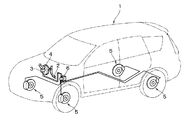
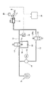
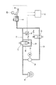
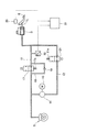
図1には本発明の一実施例に係るブレーキ装置を説明する車両の全体を表す概略構成を示してある。図2から図4にはブレーキ装置の概略系統を示してあり、図2はブレーキペダルの踏み込みによるサービスブレーキの動作時、図3は自動ブレーキの動作時でブレーキペダルが踏まれていない状態、図4は自動ブレーキの動作時でブレーキペダルが踏み込まれた状態である。
FIG. 1 shows a schematic configuration representing an entire vehicle for explaining a brake device according to an embodiment of the present invention. 2 to 4 show a schematic system of the brake device. FIG. 2 shows a state in which the service brake is operated by depressing the brake pedal, and FIG. 3 shows a state in which the brake pedal is not depressed during the automatic brake operation.
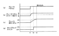
また、図5にはブレーキ装置の各構成部材の状況の経時変化を説明するタイムチャートを示してあり、図5中の実線はブレーキペダルの踏み込みによるサービスブレーキの動作時、図5中の一点差線は自動ブレーキの動作時でブレーキペダルが踏み込まれた状態である。そして、図6にはブレーキ装置の動作の状況を表すフローチャートを示してある。 FIG. 5 is a time chart for explaining the change over time of the status of each component of the brake device. The solid line in FIG. 5 indicates the difference in one point in FIG. 5 when the service brake is operated by depressing the brake pedal. The line shows the state where the brake pedal is depressed during the automatic brake operation. FIG. 6 is a flowchart showing the state of operation of the brake device.
図1に基づいてブレーキ装置の全体を説明する。 The entire brake device will be described with reference to FIG.
車両1のブレーキペダル2にはマスタシリンダー3が接続され、ブレーキペダル2を踏み込むことによりブレーキブースタ4に補助されてマスタシリンダー3が操作される。マスタシリンダー3にはブレーキ系統の経路が接続され、マスタシリンダー3が操作されることでブレーキ系統の経路に油圧が発生する。車両1の車輪の部位には液圧ブレーキとしての油圧ブレーキ(ディスクブレーキ)5が設けられ、油圧ブレーキ5のキャリパに油圧が作用することにより車輪側のディスクの回転が止められて制動される。
A
ブレーキ系統の経路には、自動ブレーキ用の油圧コントロールユニット6が設けられている。油圧コントロールユニット6は図示しない制御装置からの指令により、ブレーキ系統の経路に油圧を発生させ、油圧ブレーキ5のキャリパに油圧を作用させて自動ブレーキを動作させる。
A
図2に基づいてブレーキ系統の経路を具体的に説明する。 The route of the brake system will be specifically described based on FIG.
マスタシリンダー3につながるブレーキ系統の経路には、ブレーキペダル2の操作により油圧ブレーキ5をサービスブレーキとして作動させるサービスブレーキ系統11が備えられ、サービスブレーキの作動時にサービスブレーキ系統11に油圧が蓄えられる。
The brake system path connected to the
一方、ブレーキ系統の経路には、サービスブレーキ系統11と並列に自動ブレーキ系統12が備えられ、自動ブレーキ系統12には電動モータ13で駆動される駆動手段としての油圧ポンプ14が備えられている。油圧ポンプ14の駆動で発生した油圧により油圧ブレーキ5が自動ブレーキとして作動し、自動ブレーキの作動時に自動ブレーキ系統12から油圧ブレーキ5へ油圧が蓄えられる。
On the other hand, the brake system path is provided with an
サービスブレーキ系統11には液圧検出手段としての油圧センサー16が備えられ、油圧ブレーキ5に作用する油圧の圧力の値が油圧センサー16で検出される。つまり、油圧センサー16で検出される圧力値により油圧ブレーキ5の作動状態が推定される。
The
油圧センサー16の下流のサービスブレーキ系統11には選択手段としてのカットバルブ17が設けられている。カットバルブ17が切換えられることにより、サービスブレーキ系統11に油圧が流通する状態と、油圧センサー16の下流のサービスブレーキ系統11の油圧の流通が遮断される状態とが選択される。
The
サービスブレーキ系統11のカットバルブ17が設けられている部位には、カットバルブ17をバイパスするバイパス路18が設けられている。バイパス路18には逆止弁19が設けられ、下流側方向(油圧ブレーキ5の方向)にのみ油圧の流通が許容されている。
A
油圧ポンプ14の上流側の自動ブレーキ系統12には、ソレノイドバルブ21が設けられ、ソレノイドバルブ21が切換えられることにより、自動ブレーキ系統12に油圧が流通する状態と、油圧ポンプ14への油圧の流通が遮断される状態とが選択される。
The
電動モータ13(油圧ポンプ14)の駆動、及び、カットバルブ17、ソレノイドバルブ21の切換え動作は、車両1(図1参照)の運転状態、乗員の指示状態に応じて図示しない制御手段からの指令により制御される。例えば、先行車両との距離を所定距離に維持するための自動ブレーキや、前方の障害物を検出した際に強制的に車輪を制動させる自動ブレーキ、坂道の発進時に車両が後退しないように補助する自動ブレーキとして適用される。
The drive of the electric motor 13 (hydraulic pump 14) and the switching operation of the
ブレーキペダル2には、ブレーキペダル2の操作量(ストローク量)を電圧値により検出する操作量検出手段としてのストロークセンサー25が設けられている。ストロークセンサー25で検出された電圧値(ブレーキペダル2のストローク量)の情報は判断手段である制御手段31に送られる。また、制御手段31には油圧センサー16で検出された油圧の圧力値(油圧ブレーキ5の作動状態)の情報が入力される。
The
制御手段31では、油圧センサー16で検出される圧力値に対し、ストロークセンサー25で検出された電圧値(ブレーキペダル2のストローク量)が対応しているかどうかが判断される。
In the control means 31, it is determined whether or not the voltage value (stroke amount of the brake pedal 2) detected by the
つまり、油圧ブレーキ5の作動状態に対し、ストロークセンサー25により検出されるブレーキペダル2のストローク量が対応していないことが判断された場合、例えば、油圧センサー16が所定圧力以上であるにも拘らず、ブレーキペダル2のストローク量が少ない(ストロークセンサー25の電圧値の変化が少ない)ことが判断された場合、ストロークセンサー25の故障が判断される。
That is, when it is determined that the stroke amount of the
図2に基づいて油圧ブレーキ5をサービスブレーキとして作動させる場合を説明する。
A case where the
油圧ブレーキ5をサービスブレーキとして作動させる場合、サービスブレーキ系統11に油圧が流通する状態にカットバルブ17を動作させる。即ち、カットバルブ17の励磁をオフにして付勢ばね17aにより流路を切り替えてサービスブレーキ系統11に油圧が流通する状態にする。
When the
同時に、自動ブレーキ系統12から油圧ポンプ14への油圧の流通が遮断される状態にソレノイドバルブ21を動作させる。即ち、ソレノイドバルブ21の励磁をオフにして付勢ばね21aにより流路を切り替えて自動ブレーキ系統12の油圧の流通を遮断する状態にする。
At the same time, the
この状態で、ブレーキペダル2を操作すると、図2中太線で示すように、マスタシリンダー3からの油圧がサービスブレーキ系統11から油圧ブレーキ5に送られ、ブレーキペダル2の操作に応じた油圧力により油圧ブレーキ5が作動する。ブレーキペダル2の操作に伴いサービスブレーキ系統11の油圧が油圧センサー16で所定以上の圧力を検出したにも拘らず、ブレーキペダル2の操作前後の電圧差が小さい場合、ストロークセンサー25の故障が判断されている。
When the
この状態で、ブレーキペダル2を操作すると、図2中太線で示すように、マスタシリンダー3からの油圧がサービスブレーキ系統11から油圧ブレーキ5に送られ、ブレーキペダル2の操作に応じた油圧力により油圧ブレーキ5が作動する。サービスブレーキ系統11の油圧は油圧センサー16で検出され、ブレーキペダル2の操作に伴うストロークセンサー25の故障が判断されている。
When the
図3に基づいて油圧ブレーキ5を自動ブレーキとして作動させる場合を説明する。
A case where the
油圧ブレーキ5を自動ブレーキとして作動させる場合、サービスブレーキ系統11の油圧の流通を遮断する状態にカットバルブ17を動作させる。即ち、カットバルブ17を励磁し、付勢ばね17aの付勢力に抗して流路を切り替えてサービスブレーキ系統11の油圧の流通を遮断する状態にする。
When the
同時に、自動ブレーキ系統12から油圧ポンプ14へ油圧が流通する状態にソレノイドバルブ21を動作させる。即ち、ソレノイドバルブ21を励磁し、付勢ばね21aの付勢力に抗して流路を切り替えて自動ブレーキ系統12に油圧が流通する状態にする。
At the same time, the
この状態で、電動モータ13(油圧ポンプ14)を駆動させると、図3中太線で示すように、油圧ポンプ14の駆動に応じた油圧がマスタシリンダー3から自動ブレーキ系統12を介して油圧ブレーキ5に送られ、ブレーキペダル2の操作が行なわれない状態で油圧ブレーキ5が作動する。サービスブレーキ系統11に油圧が発生していないので油圧センサー16では油圧が検出されず、ストロークセンサー25の故障の判断は行われない。
When the electric motor 13 (hydraulic pump 14) is driven in this state, the hydraulic pressure corresponding to the driving of the
図4に基づいて油圧ブレーキ5を自動ブレーキとして作動させている際にブレーキペダル2が踏み込まれた場合を説明する。
A case where the
油圧ブレーキ5が自動ブレーキとして作動している状態(図3に示した状態)でブレーキペダル2が踏み込まれると、例えば、先行車両との距離を所定距離に維持するための自動ブレーキが作動している状態で、ブレーキペダル2が踏み込まれると、サービスブレーキ系統11に油圧が流通する状態にカットバルブ17が動作される。即ち、カットバルブ17の電磁力が開放されて付勢ばね17aにより流路が切り替えられ、サービスブレーキ系統11に油圧が流通する状態にされる。
When the
この状態では、すでに図3の状態で油圧ブレーキ5の圧力が上昇しており、図4中太線で示すように、乗員のブレーキ操作によりマスタシリンダー3のブレーキ液がサービスブレーキ系統11から油圧ブレーキ5に送られる。ブレーキペダル2の操作が少ない状態にも拘らず、すでに油圧ブレーキ5は圧力が上昇しているため、油圧センサー16で検出されるサービスブレーキ系統11の油圧の圧力値は、早期に上昇する。
In this state, the pressure of the
自動ブレーキが作動している状態でブレーキペダル2が踏み込まれると、サービスブレーキ系統11に油圧が発生するが、カットバルブ17の下流側の油圧の圧力によっては油圧がマスタシリンダー3側に逆流する虞がある。この場合、逆流の反力によりブレーキペダル2を踏み込むことが困難な状態になり、ストローク量が少ない場合であっても、油圧センサー16で検出される油圧の圧力値が高い状態になることが考えられる。
If the
また、車両の傾斜角の大きさに基づいてカットバルブ17(保持弁)を調整することで、サービスブレーキ系統で発生する油圧を保持するヒルスタートアシスト時にも、自動ブレーキ作動時と同様、ストローク量が少ない場合であっても、油圧センサー16で検出される油圧の圧力値が高い状態になることが考えられる。
Further, by adjusting the cut valve 17 (holding valve) based on the inclination angle of the vehicle, the stroke amount can be obtained at the time of hill start assist for maintaining the hydraulic pressure generated in the service brake system, as in the case of the automatic brake operation. Even when there is a small amount, it is conceivable that the pressure value of the oil pressure detected by the
つまり、ブレーキ操作により図2の状態で停車すると、ヒルスタートアシストが作動してカットバルブ17(保持弁)が閉じられる。これにより、カットバルブ17(保持弁)から油圧ブレーキ5までの系統の液圧が保持される時にも、油圧センサー16で検出される油圧の圧力値が高い状態になることが考えられる。
That is, when the vehicle is stopped in the state of FIG. 2 by a brake operation, the hill start assist is activated and the cut valve 17 (holding valve) is closed. Thereby, even when the hydraulic pressure of the system from the cut valve 17 (holding valve) to the
ヒルスタートアシストが作動している状態は、乗員のブレーキ操作によりブレーキペダル2が踏み込まれた油圧が、カットバルブ17(保持弁)の調整により適宜保持される。この場合、一度ブレーキペダルを離した後、所定時間内に再びブレーキペダルを操作した際に、逆流の反力によりブレーキペダル2を踏み込むことが困難な状態になり、ストローク量が少ない場合であっても、油圧センサー16で検出される油圧の圧力値が高い状態になる。
In the state where the hill start assist is operating, the hydraulic pressure at which the
つまり、ブレーキペダル2が踏み込まれた際に、サービスブレーキ系統11の油圧が遮断されたままの状態にカットバルブ17が制御される場合であっても、カットバルブ17までのサービスブレーキ系統11の経路長が短いため、ブレーキペダル2のストローク量が少ない状態にも拘らず油圧センサー16で検出される油圧の圧力値は高い状態になり、ストロークセンサー25の故障が判断されてしまう虞がある。
That is, even when the
油圧ブレーキ5の作動状態に対し、ストロークセンサー25により検出されるブレーキペダル2のストローク量が対応していないことが判断された場合、例えば、油圧ブレーキ5が十分に効いている状態であるにも拘らず、ブレーキペダル2のストローク量が少ない(ストロークセンサー25の電圧値の変化が少ない)ことが判断された場合、ストロークセンサー25の故障が判断されてしまう。
If it is determined that the stroke amount of the
このため、本実施例のブレーキ装置は、自動ブレーキやヒルスタートアシストが作動している時には、ストロークセンサー25の故障判断を停止し、油圧ブレーキ5が十分に効いている状態の時にブレーキペダル2のストローク量が少なくても(ストロークセンサー25の電圧値の変化が少なくても)、ストロークセンサー25が故障であると判断しないようにしている。
For this reason, the brake device of the present embodiment stops the failure determination of the
図5、図6に基づいて、自動ブレーキが作動している際にストロークセンサー25が故障であると判断しない状況を具体的に説明する。
A situation in which the
図5に基づいて各構成部材の動作状況の経時変化を説明する。 Based on FIG. 5, the change with time of the operation state of each component will be described.
油圧ブレーキ5がサービスブレーキとして作動する場合、図5(a)に示すように、時刻t1でブレーキペダル2が踏み込まれると、図5(b)に実線で示すように、ブレーキペダル2のストローク量(ストロークセンサー25の電圧値)が時刻t1のA(ブレーキオフの電圧値)から時刻t2のB(ブレーキオンの電圧値)まで増加する。
When the
図5(c)に実線で示すように、時刻t1で油圧センサー16により検出される油圧の圧力値がP1から高くなり始め、時刻t3で圧力値がP2まで増加し所望のブレーキ力が得られる。図5(d)に実線で示すように、時刻t2でストップランプスイッチがオンになり(ストップランプが点灯する状態になり)、時刻t2以降の所定時間経過時に、電圧値Aと電圧値Bの差(B−A)が所定の値を超えているかが判定される。
As shown by a solid line in FIG. 5C, the pressure value of the hydraulic pressure detected by the
時刻t2以降で、電圧値Aと電圧値Bの差(B−A)が所定値であることが判断されると、油圧センサー16により検出される油圧の圧力値P2(油圧ブレーキ5の作動状態)に対し、ブレーキペダル2のストローク量(ストロークセンサー25の電圧値)が対応していると判断される。 After time t2, when it is determined that the difference (B−A) between the voltage value A and the voltage value B is a predetermined value, the hydraulic pressure value P2 detected by the hydraulic sensor 16 (the operating state of the hydraulic brake 5) ) Is determined to correspond to the stroke amount of the brake pedal 2 (the voltage value of the stroke sensor 25).
これにより、ストロークセンサー25が正常であることが判断される。
Thereby, it is determined that the
油圧ブレーキ5が自動ブレーキとして作動している際にブレーキペダル2が踏み込まれた場合、図5(a)に示すように、時刻t1でブレーキペダル2が踏み込まれ、図5(b)に一点鎖線で示すように、ブレーキペダル2のストローク量(ストロークセンサー25の電圧値)が時刻t1のA(ブレーキオフの電圧値)から時刻t2のb(電圧値B>電圧値b)まで増加する。
When the
図5(c)に一点鎖線で示すように、時刻t1で油圧センサー16により検出される油圧の圧力値がP1から急激に高くなり、短時間で圧力値がP2まで増加し所望のブレーキ力が得られる。図5(d)に実線で示すように、時刻t2でストップランプスイッチがオンになり(ストップランプが点灯する状態になり)、時刻t2以降の所定時間経過時に、電圧値Aと電圧値bの差(b−A)が所定の値を超えているかが判定される。
As indicated by the alternate long and short dash line in FIG. 5 (c), the pressure value of the hydraulic pressure detected by the
サービスブレーキ系統11の逆流の反力によりブレーキペダル2が踏み込めず、ブレーキペダル2のストローク量は所定の値よりも小さいので(電圧値b)、時刻t2以降における所定時間経過時の電圧値Aと電圧値bの差(b−A)が小さいと判断される。故障判定カウンタの加算等により、この状態が所定回数継続して判断されることで、油圧センサー16により検出される油圧の圧力値P2に対し、ブレーキペダル2のストローク量(ストロークセンサー25の電圧値)が少ないと判断される。
Since the
これにより、ストロークセンサー25が故障であると判断されてしまう。このため、自動ブレーキが作動している時には、ストロークセンサー25が故障であると判断しないようになっている(停止手段)。
Thereby, it is determined that the
従って、自動ブレーキが作動している状態でブレーキペダル2を操作しても、ストロークセンサー25で検出されるブレーキペダル2のストローク量の検出値は、正常状態であるかの判断に反映されない。つまり、油圧ブレーキ5が十分に効いている状態の時にブレーキペダル2のストローク量が少なくても(ストロークセンサー25の電圧値の変化が少なくても)、ストロークセンサー25が故障であるとは判断しない。
Therefore, even if the
これにより、車両1の運転状況に拘わらず、ブレーキペダル2の踏み込みに対するストロークセンサー25の検出値の判断の信頼性を高めることが可能になる。
Thereby, it becomes possible to improve the reliability of the determination of the detection value of the
図6に基づいて、自動ブレーキ(ヒルスタートアシスト)が作動している時におけるストロークセンサー25の故障の判断を停止することが加味された故障判定の流れを説明する。
Based on FIG. 6, the flow of failure determination that takes into account the determination of failure of the
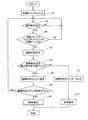
ステップS1で各種のカウンタがリセットされ、ステップS2でストロークセンサー25の故障を判断する条件である判定条件(判定許可条件)が成立しているか否かが判断される。ストロークセンサー25の故障を判断する判定許可条件は、例えば、制御電圧が所定電圧以上で所定時間継続している、ストロークセンサー25の電源が正常である(異常がない)、車両の走行を制御する制御手段との通信が正常である(異常がない)、油圧センサー16が正常である(異常がない)、車両の車速、加速度が所定値以上で所定時間継続している、との条件が全て成立した時に、判定許可条件が成立していると判断される。
In step S1, various counters are reset, and in step S2, it is determined whether a determination condition (determination permission condition) that is a condition for determining a failure of the
ステップS2で判定許可条件が成立していないと判断された場合、判定許可条件が成立するまでステップS2の判断を繰り返す。ステップS2で判定許可条件が成立していると判断された場合、ステップS3で自動ブレーキやヒルスタートアシストが作動していないか否かが判断される。ステップS3で自動ブレーキやヒルスタートアシストが作動していると判断された場合(NO)、ストロークセンサー25の故障の判断を停止する(停止手段)。再度、判定許可条件が成立し、自動ブレーキやヒルスタートアシストが作動するまで、ステップS2及びステップS3の処理を繰り返す。
If it is determined in step S2 that the determination permission condition is not satisfied, the determination in step S2 is repeated until the determination permission condition is satisfied. If it is determined in step S2 that the determination permission condition is satisfied, it is determined in step S3 whether or not automatic braking or hill start assist is operating. If it is determined in step S3 that automatic braking or hill start assist is operating (NO), the determination of failure of the
つまり、自動ブレーキやヒルスタートアシストが作動している状態でブレーキペダル2を操作しても、ストロークセンサー25で検出されるブレーキペダル2のストローク量の検出値による異常判断は行わず、油圧ブレーキ5が十分に効いている状態の時にブレーキペダル2のストローク量が少なくても(ストロークセンサー25の電圧値の変化が少なくても)、ストロークセンサー25が故障であるとは判断しない。
That is, even if the
ステップS3で自動ブレーキやヒルスタートアシストが作動していないと判断された場合、ステップS4で故障判定が許可され、ステップS5で故障条件が成立しているか否かが判断される。即ち、ブレーキペダル2のストローク量の検出値と油圧センサー16の圧力値との間の関係に基づいて、例えば、ブレーキペダル2のストローク量が所定の値よりも小さいか否か(電圧差が所定値(V)以下でありブレーキペダル2のストローク量が異常であるか否か)により故障条件が成立しているか否かが判断される。
If it is determined in step S3 that automatic braking or hill start assist is not activated, failure determination is permitted in step S4, and it is determined whether or not a failure condition is satisfied in step S5. That is, based on the relationship between the detected value of the stroke amount of the
ステップS5で故障条件が成立していると判断された場合、ステップS6で故障判定カウンタが加算される。ステップS5で故障条件が成立していないと判断された場合、ステップS7で故障判定カウンタがリセットされ、ステップS10で正常判定されて処理が終了する。 If it is determined in step S5 that the failure condition is satisfied, a failure determination counter is added in step S6. If it is determined in step S5 that the failure condition is not satisfied, the failure determination counter is reset in step S7, normal determination is made in step S10, and the process ends.
ステップS6で故障判定カウンタが加算された後、ステップS8で故障判定カウンタが所定カウント数に達したか否かが判断され、所定カウント数に達したと判断された場合、即ち、ブレーキペダル2のストローク量が異常であることが所定回数(例えば、3回)繰り返して認識された場合、ステップS9で故障判定が行われて処理が終了する。
After the failure determination counter is added in step S6, it is determined in step S8 whether or not the failure determination counter has reached a predetermined count number. If it is determined that the predetermined count number has been reached, that is, the
ステップS8で故障判定カウンタが所定カウント数に達していないと判断された場合、ステップS2の処理に移行する。 If it is determined in step S8 that the failure determination counter has not reached the predetermined count, the process proceeds to step S2.
上述したブレーキ装置は、自動ブレーキ(ヒルスタートアシスト)が作動している状態でブレーキペダル2を操作しても、ストロークセンサー25で検出されるブレーキペダル2のストローク量の検出値による異常の判断を行わないので、油圧ブレーキ5が十分に効いている状態の時にブレーキペダル2のストローク量が少なくても、ストロークセンサー25が故障であるとは判断されない。このため、自動ブレーキ(ヒルスタートアシスト)によりブレーキの制御が実施されている時であっても(車両の運転状況に拘わらず)、ブレーキペダル2のストロークセンサー25の検出値の信頼性を高めることが可能になる。
Even if the
本発明は、ブレーキペダルの操作、動力源の駆動により液圧を発生させて車輪を制動させる液圧ブレーキを備えたブレーキ装置の産業分野で利用することができる。 INDUSTRIAL APPLICABILITY The present invention can be used in the industrial field of a brake device including a hydraulic brake that brakes wheels by generating hydraulic pressure by operating a brake pedal and driving a power source.
1 車両
2 ブレーキペダル
3 マスタシリンダー
4 ブレーキブースタ
5 油圧ブレーキ
6 油圧コントロールユニット
11 サービスブレーキ系統
12 自動ブレーキ系統
13 電動モータ
14 油圧ポンプ
16 油圧センサー
17 カットバルブ
18 バイパス路
19 逆止弁
21 ソレノイドバルブ
25 ストロークセンサー
31 制御手段
DESCRIPTION OF
Claims (1)
ブレーキペダルの操作により前記液圧ブレーキの液圧を高めて前記液圧ブレーキをサービスブレーキとして作動させるサービスブレーキ系統と、
前記ブレーキペダルが操作されている際に、車両の傾きに基づいて前記サービスブレーキ系統の液圧を保持する保持弁と、
前記ブレーキペダルの操作量を検出する操作量検出手段と、
前記液圧ブレーキに作用する液圧の液圧値を検出する液圧検出手段と、
前記液圧検出手段で検出された液圧値と前記操作量検出手段で検出された操作量とに基づいて前記操作量検出手段の正常又は異常を判断する判断手段と、
前記保持弁により前記サービスブレーキの液圧が保持された後に、前記ブレーキペダルの操作をキャンセルし、所定時間内に再び前記ブレーキペダルを操作した場合に、前記判断手段による前記操作量検出手段の正常又は異常の判断を停止する停止手段とを備えた
ことを特徴とするブレーキ装置。 A hydraulic brake that applies braking force to the wheel by the hydraulic pressure of the hydraulic fluid;
A service brake system for operating the hydraulic brake as a service brake by increasing the hydraulic pressure of the hydraulic brake by operating a brake pedal;
A holding valve that holds the hydraulic pressure of the service brake system based on the inclination of the vehicle when the brake pedal is operated;
An operation amount detection means for detecting an operation amount of the brake pedal;
Hydraulic pressure detecting means for detecting the hydraulic pressure value of the hydraulic pressure acting on the hydraulic brake;
A determination means for determining whether the operation amount detection means is normal or abnormal based on the fluid pressure value detected by the fluid pressure detection means and the operation amount detected by the operation amount detection means;
After the hydraulic pressure of the service brake is held by the holding valve, when the operation of the brake pedal is canceled and the brake pedal is operated again within a predetermined time, the operation amount detection means by the determination means is normal. Or a brake device comprising stop means for stopping determination of abnormality.
Priority Applications (1)
| Application Number | Priority Date | Filing Date | Title |
|---|---|---|---|
| JP2013122169A JP6128317B2 (en) | 2013-06-10 | 2013-06-10 | Brake device |
Applications Claiming Priority (1)
| Application Number | Priority Date | Filing Date | Title |
|---|---|---|---|
| JP2013122169A JP6128317B2 (en) | 2013-06-10 | 2013-06-10 | Brake device |
Related Child Applications (1)
| Application Number | Title | Priority Date | Filing Date |
|---|---|---|---|
| JP2017004625A Division JP6268506B2 (en) | 2017-01-13 | 2017-01-13 | Brake device |
Publications (2)
| Publication Number | Publication Date |
|---|---|
| JP2014237421A JP2014237421A (en) | 2014-12-18 |
| JP6128317B2 true JP6128317B2 (en) | 2017-05-17 |
Family
ID=52134991
Family Applications (1)
| Application Number | Title | Priority Date | Filing Date |
|---|---|---|---|
| JP2013122169A Active JP6128317B2 (en) | 2013-06-10 | 2013-06-10 | Brake device |
Country Status (1)
| Country | Link |
|---|---|
| JP (1) | JP6128317B2 (en) |
Cited By (1)
| Publication number | Priority date | Publication date | Assignee | Title |
|---|---|---|---|---|
| JP3299756B2 (en) | 1993-01-18 | 2002-07-08 | セイコーインスツルメンツ株式会社 | Electronic clock |
Family Cites Families (11)
| Publication number | Priority date | Publication date | Assignee | Title |
|---|---|---|---|---|
| JPS5413133A (en) * | 1977-06-29 | 1979-01-31 | Nissan Diesel Motor Co Ltd | Automatic parking brake device |
| JPS60206757A (en) * | 1984-03-30 | 1985-10-18 | Keihin Seiki Mfg Co Ltd | Car brake device |
| JP2891166B2 (en) * | 1996-04-05 | 1999-05-17 | 三菱自動車工業株式会社 | Brake actuator |
| JPH11310119A (en) * | 1998-04-27 | 1999-11-09 | Toyota Motor Corp | Vehicle brake system |
| JP3769969B2 (en) * | 1999-03-09 | 2006-04-26 | トヨタ自動車株式会社 | Abnormality detection method for vehicle braking force control device |
| JP3714116B2 (en) * | 1999-08-09 | 2005-11-09 | トヨタ自動車株式会社 | Steering stability control device |
| JP2006123631A (en) * | 2004-10-27 | 2006-05-18 | Hitachi Ltd | Vehicle control device |
| JP5013191B2 (en) * | 2007-10-10 | 2012-08-29 | マツダ株式会社 | Vehicle travel control device |
| JP5471528B2 (en) * | 2010-02-02 | 2014-04-16 | トヨタ自動車株式会社 | Brake system |
| US9216740B2 (en) * | 2010-06-15 | 2015-12-22 | Toyota Jidosha Kabushiki Kaisha | Driving support system |
| JP5360429B2 (en) * | 2010-10-01 | 2013-12-04 | 三菱自動車工業株式会社 | Brake control device for vehicle |
-
2013
- 2013-06-10 JP JP2013122169A patent/JP6128317B2/en active Active
Cited By (1)
| Publication number | Priority date | Publication date | Assignee | Title |
|---|---|---|---|---|
| JP3299756B2 (en) | 1993-01-18 | 2002-07-08 | セイコーインスツルメンツ株式会社 | Electronic clock |
Also Published As
| Publication number | Publication date |
|---|---|
| JP2014237421A (en) | 2014-12-18 |
Similar Documents
| Publication | Publication Date | Title |
|---|---|---|
| JP4902373B2 (en) | Brake device and control method of brake device | |
| JP5497742B2 (en) | Brake device for vehicle | |
| JP5220827B2 (en) | Brake device for vehicle | |
| KR101298138B1 (en) | Brake system for a vehicle and control method the same | |
| US20120193975A1 (en) | Vehicle brake apparatus | |
| WO2010128652A1 (en) | Vehicle braking device | |
| WO2015072446A1 (en) | Vehicle control device and vehicle control system | |
| JP2007216946A (en) | Braking control device | |
| WO2014199419A1 (en) | Brake device for vehicle | |
| CN107150672A (en) | Vehicle console device | |
| CN112313132A (en) | Control device and control method for driving assistance system of motorcycle and driving assistance system for motorcycle | |
| JP6727705B2 (en) | Electric parking brake device | |
| WO2012049747A1 (en) | Brake device for vehicle and control device | |
| US20210284116A1 (en) | Brake device | |
| JP2005343248A (en) | Parking assist brake controlling device | |
| JP6128317B2 (en) | Brake device | |
| KR102813028B1 (en) | Braking systems for saddle-mounted vehicles and saddle-mounted vehicles | |
| JP2010089599A (en) | Vehicular brake device | |
| JP2008179191A (en) | Brake controller for vehicle | |
| CN112368189A (en) | Control device and control method for controlling action of motorcycle | |
| KR20120136860A (en) | Hybrid brake for vehicle | |
| JP5291807B2 (en) | Auxiliary braking device for vehicle | |
| JP6268506B2 (en) | Brake device | |
| JP2009184576A (en) | Brake device | |
| JP6354426B2 (en) | Brake device for vehicle |
Legal Events
| Date | Code | Title | Description |
|---|---|---|---|
| RD04 | Notification of resignation of power of attorney |
Free format text: JAPANESE INTERMEDIATE CODE: A7424 Effective date: 20150422 |
|
| A621 | Written request for application examination |
Free format text: JAPANESE INTERMEDIATE CODE: A621 Effective date: 20160219 |
|
| A977 | Report on retrieval |
Free format text: JAPANESE INTERMEDIATE CODE: A971007 Effective date: 20161026 |
|
| A131 | Notification of reasons for refusal |
Free format text: JAPANESE INTERMEDIATE CODE: A131 Effective date: 20161116 |
|
| A521 | Written amendment |
Free format text: JAPANESE INTERMEDIATE CODE: A523 Effective date: 20170113 |
|
| TRDD | Decision of grant or rejection written | ||
| A01 | Written decision to grant a patent or to grant a registration (utility model) |
Free format text: JAPANESE INTERMEDIATE CODE: A01 Effective date: 20170315 |
|
| A61 | First payment of annual fees (during grant procedure) |
Free format text: JAPANESE INTERMEDIATE CODE: A61 Effective date: 20170328 |
|
| R151 | Written notification of patent or utility model registration |
Ref document number: 6128317 Country of ref document: JP Free format text: JAPANESE INTERMEDIATE CODE: R151 |
|
| S531 | Written request for registration of change of domicile |
Free format text: JAPANESE INTERMEDIATE CODE: R313531 |
|
| R350 | Written notification of registration of transfer |
Free format text: JAPANESE INTERMEDIATE CODE: R350 |