JP2008179191A - Brake controller for vehicle - Google Patents
Brake controller for vehicle Download PDFInfo
- Publication number
- JP2008179191A JP2008179191A JP2007012483A JP2007012483A JP2008179191A JP 2008179191 A JP2008179191 A JP 2008179191A JP 2007012483 A JP2007012483 A JP 2007012483A JP 2007012483 A JP2007012483 A JP 2007012483A JP 2008179191 A JP2008179191 A JP 2008179191A
- Authority
- JP
- Japan
- Prior art keywords
- pressure
- brake
- control
- pump
- master cylinder
- Prior art date
- Legal status (The legal status is an assumption and is not a legal conclusion. Google has not performed a legal analysis and makes no representation as to the accuracy of the status listed.)
- Pending
Links
Images


Classifications
-
- B—PERFORMING OPERATIONS; TRANSPORTING
- B60—VEHICLES IN GENERAL
- B60T—VEHICLE BRAKE CONTROL SYSTEMS OR PARTS THEREOF; BRAKE CONTROL SYSTEMS OR PARTS THEREOF, IN GENERAL; ARRANGEMENT OF BRAKING ELEMENTS ON VEHICLES IN GENERAL; PORTABLE DEVICES FOR PREVENTING UNWANTED MOVEMENT OF VEHICLES; VEHICLE MODIFICATIONS TO FACILITATE COOLING OF BRAKES
- B60T13/00—Transmitting braking action from initiating means to ultimate brake actuator with power assistance or drive; Brake systems incorporating such transmitting means, e.g. air-pressure brake systems
- B60T13/10—Transmitting braking action from initiating means to ultimate brake actuator with power assistance or drive; Brake systems incorporating such transmitting means, e.g. air-pressure brake systems with fluid assistance, drive, or release
- B60T13/66—Electrical control in fluid-pressure brake systems
- B60T13/68—Electrical control in fluid-pressure brake systems by electrically-controlled valves
- B60T13/686—Electrical control in fluid-pressure brake systems by electrically-controlled valves in hydraulic systems or parts thereof
-
- B—PERFORMING OPERATIONS; TRANSPORTING
- B60—VEHICLES IN GENERAL
- B60T—VEHICLE BRAKE CONTROL SYSTEMS OR PARTS THEREOF; BRAKE CONTROL SYSTEMS OR PARTS THEREOF, IN GENERAL; ARRANGEMENT OF BRAKING ELEMENTS ON VEHICLES IN GENERAL; PORTABLE DEVICES FOR PREVENTING UNWANTED MOVEMENT OF VEHICLES; VEHICLE MODIFICATIONS TO FACILITATE COOLING OF BRAKES
- B60T13/00—Transmitting braking action from initiating means to ultimate brake actuator with power assistance or drive; Brake systems incorporating such transmitting means, e.g. air-pressure brake systems
- B60T13/10—Transmitting braking action from initiating means to ultimate brake actuator with power assistance or drive; Brake systems incorporating such transmitting means, e.g. air-pressure brake systems with fluid assistance, drive, or release
- B60T13/12—Transmitting braking action from initiating means to ultimate brake actuator with power assistance or drive; Brake systems incorporating such transmitting means, e.g. air-pressure brake systems with fluid assistance, drive, or release the fluid being liquid
- B60T13/16—Transmitting braking action from initiating means to ultimate brake actuator with power assistance or drive; Brake systems incorporating such transmitting means, e.g. air-pressure brake systems with fluid assistance, drive, or release the fluid being liquid using pumps directly, i.e. without interposition of accumulators or reservoirs
- B60T13/161—Systems with master cylinder
-
- B—PERFORMING OPERATIONS; TRANSPORTING
- B60—VEHICLES IN GENERAL
- B60T—VEHICLE BRAKE CONTROL SYSTEMS OR PARTS THEREOF; BRAKE CONTROL SYSTEMS OR PARTS THEREOF, IN GENERAL; ARRANGEMENT OF BRAKING ELEMENTS ON VEHICLES IN GENERAL; PORTABLE DEVICES FOR PREVENTING UNWANTED MOVEMENT OF VEHICLES; VEHICLE MODIFICATIONS TO FACILITATE COOLING OF BRAKES
- B60T8/00—Arrangements for adjusting wheel-braking force to meet varying vehicular or ground-surface conditions, e.g. limiting or varying distribution of braking force
- B60T8/32—Arrangements for adjusting wheel-braking force to meet varying vehicular or ground-surface conditions, e.g. limiting or varying distribution of braking force responsive to a speed condition, e.g. acceleration or deceleration
- B60T8/321—Arrangements for adjusting wheel-braking force to meet varying vehicular or ground-surface conditions, e.g. limiting or varying distribution of braking force responsive to a speed condition, e.g. acceleration or deceleration deceleration
- B60T8/3255—Systems in which the braking action is dependent on brake pedal data
- B60T8/3275—Systems with a braking assistant function, i.e. automatic full braking initiation in dependence of brake pedal velocity
Abstract
Description
本発明は、緊急ブレーキ時にホイールシリンダ(以下、W/Cという)の液圧(以下、W/C圧という)を早急に高められる車両用ブレーキ制御装置に関するものである。 The present invention relates to a vehicle brake control device that can quickly increase the hydraulic pressure (hereinafter referred to as W / C pressure) of a wheel cylinder (hereinafter referred to as W / C pressure) during emergency braking.
従来より、ポンプにてマスタシリンダ(以下、M/Cという)からブレーキ液を吸入し、W/Cに向けて吐出することにより、W/C圧を上昇させる車両用ブレーキ制御システムがある。このような車両用ブレーキ制御システムでは、例えば、ブレーキペダルが早踏みされた場合を緊急ブレーキ時であると判定し、緊急ブレーキ時にポンプ加圧を実施することで、W/C圧をM/Cの液圧(以下、M/C圧という)以上に上昇させるようにしている(例えば、特許文献1参照)。 2. Description of the Related Art Conventionally, there is a vehicle brake control system that increases W / C pressure by sucking brake fluid from a master cylinder (hereinafter referred to as M / C) with a pump and discharging the brake fluid toward the W / C. In such a vehicle brake control system, for example, it is determined that emergency braking is performed when the brake pedal is depressed quickly, and pump pressure is applied during emergency braking, so that the W / C pressure is set to M / C. It is made to raise more than the hydraulic pressure (henceforth M / C pressure) (for example, refer to patent documents 1).
この緊急ブレーキ時のブレーキ液圧の伝わり方について、図3を参照して説明する。図3に示されるように、緊急ブレーキ時と判定されると、M/C13とW/C14、15(34、35)とを接続する管路A(E)中に備えられた差圧制御弁16(36)を差圧状態に制御することで、W/C圧がM/C圧よりも高められる状態にしておく。そして、ポンプ19(39)にてM/C13内のブレーキ液を吸入し、差圧制御弁16(36)よりもW/C14、15(34、35)側にブレーキ液を吐出することにより、W/C圧をM/C圧よりも上昇させられるようにしている。なお、本明細書において、差圧状態とは、W/C圧とM/C圧との間に何らかの差圧が発生させられる状態のことをいう。
上記のように、ポンプ19(39)によってW/C圧を上昇させられるようにすることで、W/C14、15(34、35)の加圧をより速く、より大きくできるようにしている。しかしながら、W/C14、15(34、35)をより速く加圧できるようにしたいという要望がある。
As described above, the W / C pressure can be increased by the pump 19 (39), so that the pressurization of the W /
なお、ここでは緊急ブレーキ時にW/C圧をM/C圧よりも高められるようにするようなブレーキアシスト機能を有する車両用ブレーキ制御システムを例に上げて説明しているが、緊急ブレーキ時に、W/C圧をM/C圧の値に等しくするもので、緊急ブレーキ時ではない通常ブレーキ時と比べて、より速くW/C圧をM/C圧まで高めるような形態の場合にも、上記と同様のことが言える。 Here, a vehicle brake control system having a brake assist function that allows the W / C pressure to be higher than the M / C pressure during emergency braking is described as an example, but during emergency braking, Even when the W / C pressure is made equal to the value of the M / C pressure, and the W / C pressure is increased to the M / C pressure more quickly than in the normal braking that is not in emergency braking, The same can be said for the above.
本発明は上記点に鑑みて、緊急ブレーキ時により速くW/C圧を上昇させられるようにすることを目的とする。 In view of the above points, an object of the present invention is to increase the W / C pressure more quickly during emergency braking.
上記目的を達成するために、本発明者らは、従来の緊急ブレーキ時におけるブレーキ液の流動の仕方について考察した。 In order to achieve the above-mentioned object, the present inventors have studied how the brake fluid flows during conventional emergency braking.
従来では、緊急ブレーキ時と判定された瞬間から差圧制御弁16(36)を差圧状態にしているため、M/C13側からW/C14、15(34、35)側に向かうブレーキ液の供給経路は、差圧制御弁16(36)に並列的に備えられる踏増弁16a(36a)を通じる経路R2とポンプ19(39)を通じる経路R3となる。しかしながら、この場合、差圧制御弁16(36)を通じる経路R1は使用されない。すなわち、従来の形態では、緊急ブレーキ時には、差圧制御弁16(36)を緊急ブレーキと判定された瞬間に差圧状態に切り替えるという制御を行っており、ポンプ19(39)の応答遅れにより、実際のW/C圧が上昇する途中の過渡的な状態に関しては考慮されていない。したがって、差圧制御弁16(36)を通じる経路R1を昇圧に使用することにより、W/C圧をより速く上昇させることが可能となる。
Conventionally, since the differential pressure control valve 16 (36) is in a differential pressure state from the moment when the emergency braking is determined, the brake fluid flowing from the M /
そこで、請求項1に記載の発明では、緊急ブレーキ制御を実行するか否かの判定を行う第1判定手段(120)と、該第1判定手段により緊急ブレーキ制御を実行すると判定されたときに、差圧制御弁にてマスタシリンダとホイールシリンダとの間に差圧が発生させられる状態にすると共に、ポンプを駆動することで、ポンプにて差圧制御弁とホイールシリンダとの間に補助管路を介してブレーキ液を供給し、ホイールシリンダ圧をマスタシリンダ圧よりも高めるブレーキアシスト制御を行う第1制御手段(140、145、155)と、第1判定手段により緊急ブレーキ制御を実行すると判定されたときに、差圧制御弁を連通状態に制御する第2制御手段(145、160、175)と、第1判定手段により緊急ブレーキ制御を実行すると判定されたときのマスタシリンダからホイールシリンダへのブレーキ液の供給経路は、第2制御手段が差圧制御弁の差圧が発生させられる状態への駆動をポンプの駆動より遅らせることにより連通状態にした主管路と補助管路とを有することを特徴としている。 Therefore, in the first aspect of the invention, when it is determined that the emergency brake control is to be executed by the first determination means (120) for determining whether or not to execute the emergency brake control, and the first determination means. The differential pressure control valve is in a state where a differential pressure is generated between the master cylinder and the wheel cylinder, and the pump is driven so that the auxiliary pipe is provided between the differential pressure control valve and the wheel cylinder by the pump. It is determined that emergency brake control is to be executed by first control means (140, 145, 155) for supplying brake fluid via the road and performing brake assist control for increasing the wheel cylinder pressure higher than the master cylinder pressure, and the first determination means. When the emergency brake control is executed by the second control means (145, 160, 175) for controlling the differential pressure control valve to the communication state and the first determination means, The supply path of the brake fluid from the master cylinder to the wheel cylinder at the fixed time is set in a communication state by delaying the drive to the state where the differential pressure of the differential pressure control valve is generated by the second control means from the drive of the pump. The main line and the auxiliary line are provided.
このように、第1判定手段により緊急ブレーキ制御を実行すると判定されたときに、第2制御手段が差圧制御弁の差圧が発生させられる状態への駆動をポンプの駆動より遅らせることにより、主管路と補助管路がマスタシリンダからホイールシリンダへのブレーキ液の供給経路となるようにしている。したがって、制動開始直後の緊急ブレーキ時に、差圧制御弁を通じる経路(R1)を通じてマスタシリンダからホイールシリンダへブレーキ液を供給することができる。このため、マスタシリンダ圧の上昇に追従して、速くホイールシリンダ圧を上昇させることが可能となる。 Thus, when it is determined by the first determination means that the emergency brake control is to be executed, the second control means delays the drive to the state where the differential pressure of the differential pressure control valve is generated from the drive of the pump, The main pipeline and the auxiliary pipeline serve as a brake fluid supply path from the master cylinder to the wheel cylinder. Therefore, at the time of emergency braking immediately after the start of braking, the brake fluid can be supplied from the master cylinder to the wheel cylinder through the path (R1) through the differential pressure control valve. Therefore, it is possible to quickly increase the wheel cylinder pressure following the increase in the master cylinder pressure.
この場合、請求項2に示すように、車両用ブレーキ制御装置がポンプとマスタシリンダとの間に開閉制御弁(24、44)が備えられるブレーキ制御システム(1)に適用される場合に、第1制御手段は、緊急ブレーキ制御を実行すると判定されたときに、補助管路中において、ポンプとマスタシリンダとの間に備えられた開閉制御弁(24、44)を連通状態に制御することにより、補助管路をマスタシリンダからホイールシリンダへのブレーキ液の供給経路とすることもできる。
In this case, as shown in
このように、開閉制御弁が連通状態に制御されることにより、補助管路をマスタシリンダからホイールシリンダへのブレーキ液の供給経路にできるが、さらに上述した差圧制御弁を通じる経路(R1)もその供給経路とされるため、よりマスタシリンダ圧の上昇に追従して、速くホイールシリンダ圧を上昇させることが可能となる。 In this way, the open / close control valve is controlled to be in a communicating state, whereby the auxiliary pipe line can be used as a brake fluid supply path from the master cylinder to the wheel cylinder, but the path through the differential pressure control valve described above (R1). Therefore, the wheel cylinder pressure can be quickly increased following the increase in the master cylinder pressure.
また、請求項3に示すように、第1制御手段は、検出手段がマスタシリンダ圧に対してホイールシリンダ圧が追従していないことを検出したときに、差圧制御弁の駆動をポンプの駆動より遅らせることを特徴としている。 According to a third aspect of the present invention, when the detecting means detects that the wheel cylinder pressure does not follow the master cylinder pressure, the first control means drives the differential pressure control valve to drive the pump. It is characterized by being delayed more.
このように、検出手段がマスタシリンダ圧に対してホイールシリンダ圧が追従していないことを検出したときに、ポンプの駆動よりも差圧制御弁の駆動を遅らせることで、補助管路を通じてマスタシリンダからホイールシリンダへのブレーキ液の供給を多くすることができる。例えば、請求項2に示したように補助管路に開閉制御弁が配置される形態のブレーキ制御システムに対しては、開閉制御弁を連通状態に制御すると共にモータを駆動することで、ホイールシリンダに多くのブレーキ液を供給できる。また、開閉制御弁が備えられないようなブレーキ制御システムに関しても、同様のことが言える。
In this way, when the detecting means detects that the wheel cylinder pressure does not follow the master cylinder pressure, the master cylinder is passed through the auxiliary pipeline by delaying the drive of the differential pressure control valve rather than the pump drive. Therefore, it is possible to increase the supply of brake fluid to the wheel cylinder. For example, for a brake control system in which an open / close control valve is arranged in an auxiliary pipeline as described in
なお、請求項4に示すように、第2判定手段は、検出手段にて検出されたホイールシリンダ圧がマスタシリンダ圧から所定値を減算した値以上になったときに、差圧制御弁を駆動することができる。 The second determination means drives the differential pressure control valve when the wheel cylinder pressure detected by the detection means is equal to or greater than a value obtained by subtracting a predetermined value from the master cylinder pressure. can do.
請求項5に記載の発明では、緊急ブレーキ制御を実行するか否かの判定を行う判定手段(230)と、緊急ブレーキ制御を実行すると判定されたときに、補助管路中において、ポンプとマスタシリンダとの間に備えられた開閉制御弁(24、44)を連通状態に制御する制御手段(240)とを有し、該制御手段により、マスタシリンダからホイールシリンダへのブレーキ液は通常の主管路に加えて補助管路からも行われることを特徴としている。 According to the fifth aspect of the present invention, the determination means (230) for determining whether or not to execute the emergency brake control, and the pump and the master in the auxiliary pipe when it is determined to execute the emergency brake control. Control means (240) for controlling the open / close control valves (24, 44) provided between the cylinder and the cylinder to communicate with each other. By the control means, the brake fluid from the master cylinder to the wheel cylinder is a normal main pipe. It is characterized by being carried out from the auxiliary pipeline in addition to the road.
このように、ブレーキアシスト制御が行われない形態に対しても、緊急ブレーキ制御を実行すると判定されたときに、補助管路をマスタシリンダからホイールシリンダへのブレーキ液の供給経路とすることができる。これにより、請求項1と同様の効果を得ることができる。
As described above, even when the brake assist control is not performed, when it is determined that the emergency brake control is performed, the auxiliary pipeline can be used as a brake fluid supply path from the master cylinder to the wheel cylinder. . Thereby, the same effect as that of
例えば、請求項6に示すように、制御手段は、緊急ブレーキ制御を実行すると判定されたときに、ポンプを駆動し、該ポンプの吐出によりホイールシリンダへブレーキ液を供給することができる。 For example, when it is determined that the emergency brake control is to be executed, the control unit can drive the pump and supply brake fluid to the wheel cylinder by discharging the pump.
また、請求項7に示すように、制御手段は、緊急ブレーキ制御を実行すると判定されたときに、ポンプを駆動せず、ポンプ内の隙間を通じてホイールシリンダへブレーキ液を供給することもできる。 According to a seventh aspect of the present invention, when it is determined that the emergency brake control is to be executed, the control means can supply the brake fluid to the wheel cylinder through the gap in the pump without driving the pump.
さらに、請求項8に記載の発明では、緊急ブレーキ制御を実行するか否かの判定を行う判定手段(230)を有し、緊急ブレーキ制御を実行すると判定されたときに、補助管路中において、ポンプを駆動して、補助管路に接続された調圧リザーバ(20、40)内のブレーキ液を吸入吐出することにより、ホイールシリンダへブレーキ液を供給することを特徴としている。 Furthermore, the invention according to claim 8 further includes determination means (230) for determining whether or not to execute emergency brake control, and when it is determined to execute emergency brake control, The brake fluid is supplied to the wheel cylinder by driving the pump and sucking and discharging the brake fluid in the pressure regulating reservoir (20, 40) connected to the auxiliary pipeline.
このように、緊急ブレーキ制御を実行すると判定されたときに、補助管路中において、ポンプを駆動して、補助管路に接続された調圧リザーバ(20、40)内のブレーキ液を吸入吐出することにより、ホイールシリンダへブレーキ液を供給することもできる。これにより、補助管路をマスタシリンダからホイールシリンダへのブレーキ液の供給経路とすることができ、請求項1と同様の効果を得ることができる。 As described above, when it is determined that the emergency brake control is to be executed, the pump is driven in the auxiliary pipe, and the brake fluid in the pressure regulating reservoir (20, 40) connected to the auxiliary pipe is sucked and discharged. By doing so, it is also possible to supply brake fluid to the wheel cylinder. Thereby, the auxiliary pipeline can be used as a brake fluid supply path from the master cylinder to the wheel cylinder, and the same effect as in the first aspect can be obtained.
なお、上記各手段の括弧内の符号は、後述する実施形態に記載の具体的手段との対応関係を示すものである。 In addition, the code | symbol in the bracket | parenthesis of each said means shows the correspondence with the specific means as described in embodiment mentioned later.
以下、本発明の実施形態について図に基づいて説明する。なお、以下の各実施形態相互において、互いに同一もしくは均等である部分には、図中、同一符号を付してある。 Hereinafter, embodiments of the present invention will be described with reference to the drawings. In the following embodiments, the same or equivalent parts are denoted by the same reference numerals in the drawings.
(第1実施形態)
本発明の第1実施形態について説明する。図1は、緊急ブレーキ制御を実現するブレーキ制御システム1の全体構成を示したものである。以下、図1を参照して、本実施形態のブレーキ制御システム1について説明する。
(First embodiment)
A first embodiment of the present invention will be described. FIG. 1 shows an overall configuration of a
図1に示されるように、ブレーキ制御システム1には、ブレーキペダル11と、倍力装置12と、M/C13と、W/C14、15、34、35と、ブレーキ液圧制御用アクチュエータ(以下、ブレーキACTという)50と、電子制御装置(以下、ECUという)70とが備えられている。
As shown in FIG. 1, the
車両に制動力を加える際にドライバによって踏み込まれるブレーキ操作部材としてのブレーキペダル11は、ブレーキ液圧発生源となる倍力装置12およびM/C13に接続されており、ドライバがブレーキペダル11を踏み込むと、倍力装置12にて踏力が倍力され、M/C13に配設されたマスタピストン13a、13bを押圧する。これにより、これらマスタピストン13a、13bによって区画されるプライマリ室13cとセカンダリ室13dとに同圧のM/C圧が発生させられる。そして、このM/C圧がブレーキACT50を通じて各W/C14、15、34、35に伝えられるようになっている。
A
M/C13には、プライマリ室13cおよびセカンダリ室13dそれぞれと連通する通路を有するマスタリザーバ13eが備えられている。マスタリザーバ13eは、その通路を通じてM/C13内にブレーキ液を供給したり、M/C13内の余剰のブレーキ液を貯留したりする。
The M /
ブレーキACT50は、第1配管系統50aと第2配管系統50bとを有して構成されている。第1配管系統50aは、左前輪FLと右前輪FRに加えられるブレーキ液圧を制御するもので、第2配管系統50bは、右後輪RRと左後輪RLに加えられるブレーキ液圧を制御するものであり、これら第1、第2配管系統50a、50bの2配管系により前後配管が構成されている。
The
以下、第1、第2配管系統50a、50bについて説明するが、第1配管系統50aと第2配管系統50bとは、略同様の構成であるため、ここでは第1配管系統50aについて説明し、第2配管系統50bについては、第1配管系統50aを参照して説明を省略する。
Hereinafter, the first and
第1配管系統50aには、上述したM/C圧を左前輪FLに備えられたW/C14及び右前輪FRに備えられたW/C15に伝達する主管路となる管路Aが備えられている。この管路Aを通じて、各W/C14、15それぞれにW/C圧が発生させられる。
The
また、管路Aには、連通・差圧・遮断状態に制御できる電磁弁で構成された周知構成の第1差圧制御弁16が備えられている。構成については、特開平10−152041号公報に詳述されているのでここでは記載を省略する。第1差圧制御弁16は、ソレノイドコイルに流す電流の値に応じて差圧値をリニアに調整でき、その電流値を所定値まで大きくすると遮断状態となる構成とされている。この第1差圧制御弁16は、通常ブレーキ状態では連通状態、緊急ブレーキ時においてソレノイドコイルに電力供給が為されると差圧状態もしくは遮断状態となる。第1差圧制御弁16が差圧状態のときに、W/C圧がM/C圧よりも所定以上高くなると、W/C14、15側からM/C13側へのみブレーキ液の流動が許可される。このため、常時W/C14、15側がM/C13側よりも所定圧力以上高くならないように維持され、それぞれの管路の保護が為されている。
Further, the pipe A is provided with a first differential
管路Aは、この第1差圧制御弁16よりもW/C14、15側の下流において、2つの管路A1、A2に分岐する。2つの管路A1、A2の一方にはW/C14へのブレーキ液圧の増圧を制御する増圧制御弁17が備えられ、他方にはW/C15へのブレーキ液圧の増圧を制御する増圧制御弁18が備えられている。
The pipe A branches into two pipes A1 and A2 downstream of the first differential
各増圧制御弁17、18は、連通・遮断状態を制御できる2位置弁として電磁弁により構成されている。これら増圧制御弁17、18が連通状態に制御されているときには、M/C圧あるいは後述するポンプ19からのブレーキ液の吐出によるブレーキ液圧をW/C14、15に加えられる。
Each of the pressure
なお、ドライバが行うブレーキペダル11の操作による通常のブレーキ時においては、第1差圧制御弁16及び増圧制御弁17、18は、常時連通状態に制御されている。
Note that, during normal braking by the operation of the
また、第1差圧制御弁16及び増圧制御弁17、18には、それぞれ踏増弁16aや安全弁17a、18aが並列に設けられている。第1差圧制御弁16の踏増弁16aは、第1差圧制御弁16が差圧状態もしくは遮断状態の際にドライバによりブレーキペダル11が踏み込まれた場合に、M/C圧をW/C14、15に伝達可能とするために設けられている。また、各増圧制御弁17、18の安全弁17a、18aは、特にABS制御時において各増圧制御弁17、18が遮断状態に制御されている際に、ドライバによりブレーキペダル11が戻された場合において、この戻し操作に対応して左前輪FLおよび右前輪FRのW/C圧を減圧可能とするために設けられている。
The first differential
管路Aにおける増圧制御弁17、18及び各W/C14、15の間とリザーバ20とを結ぶ減圧管路としての管路Bには、連通・遮断状態を制御できる2位置弁として、電磁弁からなる減圧制御弁21、22がそれぞれ配設されている。そして、これら減圧制御弁21、22は、通常ブレーキ時には、常時遮断状態とされている。
The pressure-increasing
リザーバ20と主管路である管路Aとの間を結ぶように還流管路となる管路Cが配設されている。この管路Cにはリザーバ20からM/C13側あるいはW/C14、15側に向けてブレーキ液を吸入吐出するように、モータ60によって駆動される自吸式のポンプ19が設けられている。
A conduit C serving as a reflux conduit is disposed so as to connect between the
なお、ポンプ19の吐出口側には、ポンプ19に対して高圧なブレーキ液が加えられないように、安全弁19aが備えられている。また、ポンプ19が吐出したブレーキ液の脈動を緩和するために管路Cのうちポンプ19の吐出側には固定容量ダンパ23が配設されている。
A
そして、リザーバ20とM/C13とを接続するように補助管路となる管路Dが設けられており、管路Dには開閉制御弁24が備えられている。開閉制御弁24は、連通・遮断状態を制御できる2位置弁として電磁弁により構成され、非通電時には遮断状態、通電時には連通状態となる。この開閉制御弁24により、管路Dの連通・遮断状態が制御され、開閉制御弁24が連通状態の際には、管路Dを通じ、ポンプ19にてM/C13からブレーキ液を吸入し、管路Aに吐出することで、緊急ブレーキ時などにおいて、W/C14、15側にブレーキ液を供給し、W/C圧をM/C圧よりも高くできる構成とされている。
A pipeline D serving as an auxiliary pipeline is provided so as to connect the
一方、上述したように、第2配管系統50bは、第1配管系統50aにおける構成と略同様となっている。つまり、第1差圧制御弁16および踏増弁16aは、第2差圧制御弁36および踏増弁36aに対応する。増圧制御弁17、18および安全弁17a、18aは、それぞれ第3、第4増圧制御弁37、38および安全弁37a、38aに対応し、減圧制御弁21、22は、それぞれ第3、第4減圧制御弁41、42に対応する。リザーバ20は、リザーバ40に対応する。ポンプ19は、ポンプ39に対応する。ダンパ23は、ダンパ43に対応する。開閉制御弁24は、開閉制御弁44と対応する。また、管路A、管路B、管路C、管路Dは、それぞれ管路E、管路F、管路G、管路Hに対応する。以上のようにブレーキ制御システム1における液圧配管構造が構成されている。
On the other hand, as described above, the
また、ブレーキ制御システム1には、車輪速度センサ71〜74も備えられている。車輪速度センサ71〜74は、各車輪FL〜RRに対応して配設され、各車輪FL〜RRの回転速度、すなわち車輪速度に比例するパルス数のパルス信号をECU70に向けて出力する。
The
さらに、ブレーキ制御システム1には、M/C圧センサ75、W/C圧センサ76〜79およびストップランプスイッチ80が備えられている。W/C圧センサ76〜79は、各W/C14、15、34、35で発生しているW/C圧を検出するものである。ストップランプスイッチ80は、制動中にONされるものであり、ストップランプスイッチ80の状態を利用して制動中か否かを判定することが可能となる。これらW/C圧センサ76〜79およびストップランプスイッチ80の検出信号もECU70に入力されている。
Further, the
ECU70は、本発明の車両用ブレーキ制御装置に相当するものであり、CPU、ROM、RAM、I/Oなどを備えた周知のマイクロコンピュータによって構成される。ECU70では、車輪速度センサ71〜74やW/C圧センサ76〜79およびストップランプスイッチ80の検出信号等を受け取り、これら各検出信号を用いて、ROMなどに記憶されたプログラムに従って緊急ブレーキを含めた様々なブレーキ制御に関する処理を実行する。
The
このECU70からの制御信号に基づいて、上記のように構成されたブレーキACT50における各制御弁16〜18、21、22、24、36〜38、41、42、44及びポンプ19、39を駆動するためのモータ60への電流供給が制御され、これにより、各W/C14、15、34、35に発生させられるW/C圧の制御が行われる。
Based on the control signal from the
続いて、本実施形態のブレーキ制御システム1の作動について説明する。上述した構成のブレーキ制御システム1によれば、緊急ブレーキに加えて、ABS(アンチスキッド)制御等のブレーキ制御を実行できるが、ここでは緊急ブレーキが特徴となる部分であるため、緊急ブレーキ時とブレーキ制御が実行されない通常ブレーキ時についてのみ説明する。
Subsequently, the operation of the
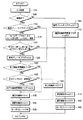
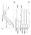
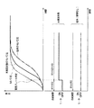
図2は、ECU70にて実行される緊急ブレーキ制御処理のフローチャートである。図3は、緊急ブレーキ時や通常ブレーキ時におけるブレーキ制御システム1の配管形態を簡略化して示した図である。また、図4は、制動開始初期からの時間経過に伴うM/C圧およびW/C圧の変化を本実施形態の制御を行う場合と従来のように本実施形態の制御を行わない場合それぞれについて示したタイミングチャートである。以下、これらの図を参照して緊急ブレーキ時および通常ブレーキ時の動作について説明する。
FIG. 2 is a flowchart of an emergency brake control process executed by the
図2に示す緊急ブレーキ制御処理は、図示しないイグニッションスイッチがOFFからONに切り替えられた際に、予め決められた演算周期毎に実行される。まず、ステップ100では、入力処理を実行する。この入力処理により、各種センサ類の検出信号の入力や制御に用いられる演算値の入力を行う。具体的には、M/C圧センサ75やW/C圧センサ76〜79およびストップランプスイッチ80の検出信号等が入力される。
The emergency brake control process shown in FIG. 2 is executed every predetermined calculation cycle when an ignition switch (not shown) is switched from OFF to ON. First, in
ステップ105では、制動中であるか否かを判定する。この判定はストップランプスイッチ80がONされているか否かに基づいて行われ、ストップランプスイッチ80がONされていれば制動中であると判定される。すなわち、制動中にのみ緊急ブレーキが必要になるため、肯定判定された場合にのみステップ110に進む。
In
続く、ステップ110では、緊急ブレーキフラグがONされているか否かを判定する。緊急ブレーキフラグとは、緊急ブレーキ時(緊急ブレーキの必要性あり)と判定された場合にONされるフラグであり、ECU70に備えられた図示しないメモリ内に備えられている。この判定は、後述するステップ120において行われる。ここで制動開始直後であれば、ステップ110において否定判定され、ステップ115に進む。
In the
ステップ115では、ステップ100で入力されたM/C圧PMCに基づき、M/C圧勾配dPMCを演算する。この演算は、例えば、今回の演算周期に求められたM/C圧と前回の演算周期に求められたM/C圧との差として求められる。そして、ステップ120に進み、M/C圧PMCが第1しきい値よりも大きく、かつ、M/C圧勾配dPMCが第2しきい値よりも大きいか否かを判定する。M/C圧PMCが第1しきい値より大きい場合とは、ブレーキペダル11が大きく踏み込まれ、高い制動力を発生させたいという要求が有ることを示すもので、M/C圧勾配dPMCが第2しきい値より大きい場合とは、ブレーキペダル11の踏み込み速度が早く、緊急性が高いことを示している。このような場合には、緊急ブレーキが必要であると考えられる。従って、ステップ120で肯定判定されれば、ステップ125に進み、緊急ブレーキフラグをオンする。
In
続いて、ステップ130に進み、差圧制御弁閉要求フラグがONされているか否かを判定する。差圧制御弁閉要求フラグとは、ブレーキアシスト制御を実行すると判定された場合にONされるフラグ、つまり第1、第2差圧制御弁16、36を遮断状態にするという要求を示すフラグであり、ECU70に備えられたRAM等のメモリ内に備えられている。この判定は、次のステップ135において実行される。具体的には、今回の演算周期に求められたM/C圧から所定値を減算した値よりもW/C圧センサ76〜79の検出信号に基づいて演算されたW/C圧が大きいか否かを判定する。すなわち、上述した緊急ブレーキ時であると判定された場合にはブレーキアシスト制御を同時に実行することになるが、W/C圧をM/C圧以上に高める前の過渡的な段階において、W/C圧の上昇がM/C圧の上昇に追従できていればW/C圧の上昇を速める必要が無いが、追従できていなければW/C圧の上昇を速める必要がある。
Subsequently, the routine proceeds to step 130, where it is determined whether or not the differential pressure control valve closing request flag is ON. The differential pressure control valve closing request flag is a flag that is turned on when it is determined that brake assist control is to be executed, that is, a flag that indicates a request to turn off the first and second differential
したがって、ステップ135で肯定判定されればステップ140に進み、差圧制御弁閉要求フラグをONさせる。この後、ステップ145に進み、第1、第2差圧制御弁16、36への通電をONさせる。このとき、第1、第2差圧制御弁16、36を遮断状態にするのに必要な電流値の電流を流す。そして、ステップ150にて、開閉制御弁24、44への通電をONさせ、これらを連通状態にすると共に、ステップ155にて、モータ60に対しても通電すべく、図示しないモータリレーをONさせる。
Therefore, if an affirmative determination is made in
このような形態とされる場合、第1、第2差圧制御弁16、36が差圧状態とされるため、図3に示した踏増弁16a、36aを通じる経路R2とポンプ19、39を通じる経路R3を通ってM/C13から各W/C14、15、34、35へのブレーキ液の供給が可能となる。
In such a configuration, the first and second differential
一方、W/C圧をM/C圧以上に高める前の過渡的な段階において、W/C圧の上昇がM/C圧の上昇に追従できていない場合、ステップ135で否定判定される。この場合には、M/C圧の上昇に比べてW/C圧の上昇が遅れることから、より速くW/C圧を上昇させられるようにしたい。このため、W/C圧がM/C圧から所定値を減算した値より小さければ、まだW/C圧の上昇が足りないものとして、ステップ160に進み、第1、第2差圧制御弁16、36への通電をOFFにする。そして、ステップ150にて、開閉制御弁24、44への通電をONさせ、これらを連通状態にすると共に、ステップ155にて、モータ60に対しても通電すべく、図示しないモータリレーをONさせる。
On the other hand, if the increase in the W / C pressure cannot follow the increase in the M / C pressure in the transitional stage before the W / C pressure is increased to the M / C pressure or higher, a negative determination is made in
このような形態とされる場合、第1、第2差圧制御弁16、36が連通状態とされるため、図3中、踏増弁16a、36aを通じる経路R2とポンプ19、39を通じる経路R3に加え、第1、第2差圧制御弁16、36を通じる経路R1も通ってM/C13から各W/C14、15、34、35へのブレーキ液の供給が可能となる。
In such a configuration, since the first and second differential
そして、制動が終了すると、上述したステップ105において、制動中ではないと否定判定され、ステップ165にて緊急ブレーキフラグをOFFにすると共に、ステップ170にて差圧制御弁閉要求フラグをOFFにする。さらに、ステップ175において、第1、第2差圧制御弁16、36への通電をOFFすると共に、ステップ180にて開閉制御弁24、44への通電もOFFし、ステップ185にてモータ60への通電もOFFすべくモータリレーもOFFする。
When braking is completed, a negative determination is made in
同様に、ステップ120において、緊急ブレーキ時とは判定されなかった場合にも、ステップ175〜185に進み、第1、第2差圧制御弁16、36や開閉制御弁24、44への通電をOFFし、モータリレーもOFFする。この場合が通常ブレーキ時に相当し、各制御弁16〜18、21、22、24、36〜38、41、42、44は図1に示す状態とされているため、M/C圧がそのままW/C圧に伝えられることになる。
Similarly, if it is not determined in
以上のような緊急ブレーキ制御処理が実行された場合、まず、図4中の制動開始直後の期間T1、つまり緊急ブレーキ時と判定される前までは、通常ブレーキ時の動作となり、第1、第2差圧制御弁16、36や開閉制御弁24、44への通電はOFF、モータリレーもOFFとなる。このため、図3中の経路R1、R2を通じてM/C13からW/C14、15、34、35へブレーキ液が供給される。
When the emergency brake control process as described above is executed, first, during the period T1 immediately after the start of braking in FIG. The energization of the two differential
続いて、緊急ブレーキ時と判定されたのちW/C圧が十分に上昇するまでの期間T2では、緊急ブレーキ時の動作となるが、このときにはW/C圧がM/C圧から所定値を減算した値よりも小さいため、開閉制御弁24への通電はON、モータリレーもONにされるものの、第1、第2差圧制御弁16、36への通電はOFFのままとされる。このため、図3中の経路R1、R2、R3すべてを通じてM/C13からW/C14、15、34、35へブレーキ液が供給される。なお、従来の場合、この期間T2という過渡的な期間中にも第1、第2差圧制御弁16、36への通電をONしているため、図3中の経路R2、R3のみを通じてM/C13からW/C14、15、34、35へブレーキ液が供給されることになる。
Subsequently, during the period T2 until the W / C pressure sufficiently rises after it is determined that the emergency brake is being performed, the operation is performed during an emergency brake. Since it is smaller than the subtracted value, the energization to the open /
その後、W/C圧がM/C圧から所定値を減算した値よりも大きくなった期間T3には、第1、第2差圧制御弁16、36への通電もONされる。そして、W/C圧がM/C圧以上に高くなると、図3中の経路R3のみを通じてM/C13からW/C14、15、34、35へブレーキ液が供給されることになる。なお、図4では、W/C圧をM/C圧から所定値を減算した値と大小比較するときの所定値をゼロとした場合を例に挙げているが、このように所定値をゼロとしても良い。
Thereafter, energization of the first and second differential
以上説明したように、本実施形態のブレーキ制御システム1によれば、制動開始直後の緊急ブレーキ時に、第1、第2差圧制御弁16、36への通電をまだOFFにし、差圧制御弁の差圧状態への駆動をポンプ19、39の駆動より期間T2だけ遅らせることで、T2の期間、図3中の経路R1、R2、R3すべてを通じてM/C13からW/C14、15、34、35へブレーキ液を供給することができる。このため、M/C圧の上昇に追従して、速くW/C圧を上昇させることが可能となる。特に、経路R1は、第1、第2差圧制御弁16、36が連通状態のときには、非常に小さな流動抵抗でブレーキ液を供給できるため、W/C圧の上昇をより速めることが可能となる。
As described above, according to the
(第2実施形態)
本発明の第2実施形態について説明する。本実施形態は、第1実施形態に示したブレーキ制御システム1において、緊急ブレーキ時にブレーキアシスト制御を実行しない場合について説明する。なお、本実施形態は、第1実施形態に対してECU70で実行する緊急ブレーキ制御処理を一部変更したものであり、その他に関しては第1実施形態と同様であるため、異なる部分についてのみ説明する。
(Second Embodiment)
A second embodiment of the present invention will be described. This embodiment demonstrates the case where brake assist control is not performed in emergency braking in the
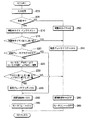
図5は、本実施形態のECU70が実行する緊急ブレーキ制御処理のフローチャートである。また、図6は、制動開始初期からの時間経過に伴うM/C圧およびW/C圧の変化を本実施形態の制御を行う場合と従来のように本実施形態の制御を行わない場合それぞれについて示したタイミングチャートである。以下、これらの図を参照して緊急ブレーキ時および通常ブレーキ時の動作について説明する。
FIG. 5 is a flowchart of the emergency brake control process executed by the
まず、ステップ200、205では、図2のステップ100、105と同様の処理を行う。そして、ステップ205で肯定判定された場合には、ステップ210に進む。
First, in
ステップ210では制動中タイマをインクリメントし、さらにステップ215では制動中タイマが第3しきい値を超えているか否かを判定する。制動中タイマは、制動中であると判定されてからの経過時間を計測するものである。緊急ブレーキ制御は、制動を開始した直後に必要とされるものであり、W/C圧が十分に上昇した後や緊急性がない場合には必要とされない。したがって、制動開始から所定時間達したことを、制動中タイマが第3しきい値を超えたか否かにより判定し、制動中タイマが第3しきい値を超えるまでの期間が緊急ブレーキ制御の必要がある期間として位置づけられている。なお、制動中タイマは演算周期毎にインクリメントされるため、演算周期×第3しきい値が緊急ブレーキ制御の必要がある期間(所定時間)に相当する。
In
そして、ステップ215で否定判定された場合には、ステップ220〜235において、図2のステップ110〜125と同様の処理を行う。ステップ220で否定判定されたのちステップ230で肯定判定された場合、および、ステップ220で肯定判定された場合には、ステップ240に進む。そして、ステップ240、245において、図2のステップ150、155と同様の処理を行い、開閉制御弁24、44への通電をONすると共に、モータリレーをONにする。
If a negative determination is made in
このような形態とされる場合、第1、第2制御弁16、36に関しては通常ブレーキ時から変化が無い状態、つまり連通状態のままにされるため、図3に示した経路R1〜R3すべてを通ってM/C13から各W/C14、15、34、35へのブレーキ液の供給が可能となる。
In such a configuration, the first and
そして、制動が終了すると、上述したステップ205において、制動中ではないと否定判定され、ステップ250にて制動中タイマを0にリセットすると共に、ステップ255にて緊急ブレーキフラグをOFFにする。さらに、ステップ260にて開閉制御弁24、44への通電をOFFし、ステップ265にてモータ60への通電もOFFすべくモータリレーもOFFする。
When braking is completed, a negative determination is made in
同様に、ステップ230において、緊急ブレーキ時とは判定されなかった場合にも、ステップ260、265に進み、開閉制御弁24、44への通電をOFFし、モータリレーもOFFする。この場合が通常ブレーキ時に相当し、各制御弁16〜18、21、22、24、36〜38、41、42、44は図1に示す状態とされているため、M/C圧がそのままW/C圧に伝えられることになる。
Similarly, if it is not determined in
以上のような緊急ブレーキ制御処理が実行された場合、まず、図6中の制動開始直後の期間T1、つまり緊急ブレーキ時と判定される前までは、通常ブレーキ時の動作となり、開閉制御弁24、44への通電はOFF、モータリレーもOFFとなる。このため、図3中の経路R1、R2を通じてM/C13からW/C14、15、34、35へブレーキ液が供給される。
When the emergency brake control process as described above is executed, first, during the period T1 immediately after the start of braking in FIG. 6, that is, before the emergency brake is determined, the normal brake operation is performed, and the open /
続いて、緊急ブレーキ時と判定されたのちW/C圧が十分に上昇するまでの期間T2では、緊急ブレーキ時の動作となるが、このときには開閉制御弁24、44への通電はON、モータリレーもONにされる。このとき、第1、第2差圧制御弁16、36への通電はOFFのままである。このため、図3中の経路R1、R2、R3すべてを通じてM/C13からW/C14、15、34、35へブレーキ液が供給される。なお、従来の場合、この期間T2という過渡的な期間中にはモータ60への通電が行われないため、図3中の経路R1、R2のみを通じてM/C13からW/C14、15、34、35へブレーキ液が供給されることになる。そして、制動中タイマが第3しきい値を超えると、緊急ブレーキ制御を終え、通常ブレーキとされる。
Subsequently, during the period T2 until the W / C pressure is sufficiently increased after the emergency braking is determined, the emergency braking operation is performed. At this time, the energization of the open /
以上説明したように、本実施形態のブレーキ制御システム1によれば、制動開始直後の緊急ブレーキ時に、ブレーキアシスト制御を実行しなくてもポンプ19、39を駆動することにより、図3中の経路R1、R2、R3すべてを通じてM/C13からW/C14、15、34、35へブレーキ液を供給することができる。このため、M/C圧の上昇に追従して、速くW/C圧を上昇させることが可能となる。
As described above, according to the
なお、図5のステップ245を括弧で囲んでいるが、モータリレーをONすることは必須ではない。すなわち、本実施形態のように緊急ブレーキ時に開閉制御弁24、44への通電をONした場合、管路D、Hを通じてM/C13とリザーバ20、40が連通状態になるが、リザーバ20、40に蓄積されたブレーキ液はポンプ19、39による吸入・吐出動作を行わなくても、ポンプ19、39の隙間を通じてW/C14、15、34、35側に供給することができる。このため、ポンプ19、39を駆動した場合と比べれば少ないながらも図3中の経路R3を通じたブレーキ液の供給を行える。したがって、モータリレーをONさせなくても、従来と比べ、M/C圧の上昇に追従して、速くW/C圧を上昇させることが可能となる。
Note that although
(第3実施形態)
本発明の第3実施形態について説明する。本実施形態は、第1実施形態に示したブレーキ制御システム1の構造および緊急ブレーキ制御処理を一部変更したものである。このため、第1実施形態と同様の部分に関しては省略し、異なる部分についてのみ説明する。
(Third embodiment)
A third embodiment of the present invention will be described. In the present embodiment, the structure of the
図7は、本実施形態のブレーキ制御システム1の全体構成を示したものである。図7に示すように、第1実施形態で示したリザーバ20、40を調圧リザーバにて構成し、開閉制御弁24、44を無くした構造とされている。つまり、第1実施形態では、ブレーキ制御システム1が12個の制御弁を備えた構造とされているが、本実施形態では10個の制御弁を備えた構造とされている。
FIG. 7 shows the overall configuration of the
リザーバ20は、管路Dに接続されてM/C13側からのブレーキ液を受け入れるリザーバ孔20aと、管路B及び管路Cに接続されW/C14、15から逃がされるブレーキ液を受け入れると共にポンプ19の吸入側にブレーキ液を供給するリザーバ孔20bとが備えられ、これらがリザーバ室20cと連通している。リザーバ孔20aより内側には、ボール弁20dが配設されている。このボール弁20dには、ボール弁20dを上下に移動させるための所定ストロークを有するロッド20fがボール弁20dと別体で設けられている。
The
また、リザーバ室20c内には、ロッド20fと連動するピストン20gと、このピストン20gをボール弁20d側に押圧してリザーバ室20c内のブレーキ液を押し出そうとする力を発生するスプリング20hが備えられている。
Also, in the
このように構成されたリザーバ20は、所定量のブレーキ液が貯留されると、ボール弁20dが弁座20eに着座してリザーバ20内にブレーキ液が流入しないようになっている。このため、ポンプ19の吸入能力より多くのブレーキ液がリザーバ室20c内に流動することがなく、ポンプ19の吸入側に高圧が印加されないようになっている。
In the
リザーバ40は、リザーバ20と同様の構造とされており、各構成要素40a〜40hがそれぞれリザーバ20の各構成要素20a〜20hと同様の働きをする。
The
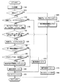
図8は、本実施形態のECU70が実行する緊急ブレーキ制御処理のフローチャートである。図9は、緊急ブレーキ時や通常ブレーキ時におけるブレーキ制御システム1の配管形態を簡略化して示した図である。
FIG. 8 is a flowchart of the emergency brake control process executed by the
図8に示すように、本実施形態の場合、第1実施形態で示した図2のステップ150およびステップ180の処理を無くした処理により、緊急ブレーキ制御処理を実行することができる。
As shown in FIG. 8, in the case of the present embodiment, the emergency brake control process can be executed by the process that eliminates the process of
具体的には、緊急ブレーキ時には、基本的にはブレーキアシスト制御を実行するが、W/C圧がM/C圧から所定値減算する値を超えるまでは第1、第2差圧制御弁16、36が連通状態にされる。この状態においては、図9中の経路R1、R2が通じていると共に、リザーバ20、40とM/C13とが管路D、Hを通じて連通状態となっているため、ポンプ19、39を駆動することにより、図9中の経路R3も通じた状態となる。したがって、経路R1〜R3すべてを通じてM/C13からW/C14、15、34、35へブレーキ液を供給することができる。このため、M/C圧の上昇に追従して、速くW/C圧を上昇させることが可能となる。そして、W/C圧がM/C圧から所定値減算する値を超えると、第1、第2差圧制御弁16、36が遮断状態とされ、経路R3(もしくは経路R2、R3)を通じてM/C13からW/C14、15、34、35へブレーキ液を供給することができる。
Specifically, during emergency braking, brake assist control is basically executed, but the first and second differential
また、通常ブレーキ時には、第1、第2差圧制御弁16、36が連通状態にされているため、ブレーキペダル11が踏み込まれてM/C圧が発生すると、図9中の経路R1、R2を通じてM/C13からW/C14、15、34、35へブレーキ液を供給することができる。
Further, during normal braking, the first and second differential
このような緊急ブレーキ制御処理が実行された場合、ブレーキ制御システム1は、上述した第1実施形態と同様の作動、つまり図4のタイミングチャートと同様の作動が行われる。このため、第1実施形態と同様の効果を得ることができる。
When such an emergency brake control process is executed, the
(第4実施形態)
本発明の第4実施形態について説明する。本実施形態は、第3実施形態に示したブレーキ制御システム1において、緊急ブレーキ時にブレーキアシスト制御を実行しない場合について説明する。なお、本実施形態は、第2実施形態に対してECU70で実行する緊急ブレーキ制御処理を一部変更したものであり、その他に関しては第2実施形態と同様であるため、異なる部分についてのみ説明する。
(Fourth embodiment)
A fourth embodiment of the present invention will be described. This embodiment demonstrates the case where brake assist control is not performed at the time of emergency braking in the
図10は、本実施形態のECU70が実行する緊急ブレーキ制御処理のフローチャートである。また、図11は、制動開始初期からの時間経過に伴うM/C圧およびW/C圧の変化を本実施形態の制御を行う場合と従来のように本実施形態の制御を行わない場合それぞれについて示したタイミングチャートである。
FIG. 10 is a flowchart of emergency brake control processing executed by the
図10に示すように、本実施形態の場合、第2実施形態で示した図5のステップ240およびステップ260の処理を無くした処理により、緊急ブレーキ制御処理を実行することができる。 As shown in FIG. 10, in the case of the present embodiment, the emergency brake control process can be executed by the process in which the processes of Step 240 and Step 260 of FIG. 5 shown in the second embodiment are eliminated.
具体的には、緊急ブレーキ時には、W/C圧が十分に上昇するまで、モータリレーがONにされる。このとき、第1、第2差圧制御弁16、36への通電はOFFのままである。このため、図9中の経路R1〜R3すべてを通じてM/C13からW/C14、15、34、35へブレーキ液が供給される。そして、制動中タイマが第3しきい値を超えると、緊急ブレーキ制御を終え、通常ブレーキとされる。
Specifically, at the time of emergency braking, the motor relay is turned on until the W / C pressure sufficiently increases. At this time, the energization to the first and second differential
また、通常ブレーキ時には、第1、第2差圧制御弁16、36が連通状態にされているため、ブレーキペダル11が踏み込まれてM/C圧が発生すると、図9中の経路R1、R2を通じてM/C13からW/C14、15、34、35へブレーキ液を供給することができる。
Further, during normal braking, the first and second differential
このような緊急ブレーキ制御処理が実行された場合、ブレーキ制御システム1は、上述した第2実施形態と同様の作動、つまり図6のタイミングチャートと同様の作動が行われる。このため、第2実施形態と同様の効果を得ることができる。
When such an emergency brake control process is executed, the
(他の実施形態)
上記各実施形態では、制御弁の数が12個もしくは10個のものを代表例として示したが、第1、第2差圧制御弁16、36が備えられると共に、ポンプ19、39にて第1、第2差圧制御弁16、36と各W/C14、15、34、35の間にブレーキ液を吐出できるような構造のものであれば、制御弁がどのような数であっても構わない。
(Other embodiments)
In the above embodiments, the number of control valves is 12 or 10 as a representative example. However, the first and second differential
また、上記実施形態では、M/C圧をM/C圧センサ75の検出信号に基づいて検出し、W/C圧をW/C圧センサ76〜79の検出信号に基づいて検出している。しかしながら、これらは単なる一例であり、例えばブレーキペダル11のストローク量や踏力に基づいてM/C圧を演算したり、M/C圧と第1、第2差圧制御弁16、36に流す電流の電流値やポンプ19、39に流す電流の電流値などからW/C圧を換算したりするなど、周知となっている他の手法によりM/C圧やW/C圧を求めるようにしても良い。
Moreover, in the said embodiment, M / C pressure is detected based on the detection signal of the M /
なお、各図中に示したステップは、各種処理を実行する手段に対応するものである。 The steps shown in each figure correspond to means for executing various processes.
1…ブレーキ制御システム、11…ブレーキペダル、12…倍力装置、13…M/C、14、15、34、35…W/C、16、36…第1、第2差圧制御弁、16a、36a…踏増弁、19、39…ポンプ、20、40…リザーバ、24、44…開閉制御弁、60…モータ、70…ECU、71〜74…車輪速度センサ、75…M/C圧センサ、76〜79…W/C圧センサ、80…ストップランプスイッチ、FL〜FR…各車輪。
DESCRIPTION OF
Claims (8)
緊急ブレーキ制御を実行するか否かの判定を行う第1判定手段(120)と、
該第1判定手段により前記緊急ブレーキ制御を実行すると判定されたときに、前記差圧制御弁にて前記マスタシリンダと前記ホイールシリンダとの間に差圧が発生させられる状態にすると共に、前記ポンプを駆動することで、前記ポンプにて前記差圧制御弁と前記ホイールシリンダとの間に前記補助管路を介してブレーキ液を供給し、前記ホイールシリンダ圧を前記マスタシリンダ圧よりも高めるブレーキアシスト制御を行う第1制御手段(140、145、155)と、
前記第1判定手段により前記緊急ブレーキ制御を実行すると判定されたときに、前記差圧制御弁を連通状態に制御する第2制御手段(145、160、175)と、
前記第1判定手段により前記緊急ブレーキ制御を実行すると判定されたときの前記マスタシリンダから前記ホイールシリンダへのブレーキ液の供給経路は、前記第2制御手段が前記差圧制御弁の前記差圧が発生させられる状態への駆動を前記ポンプの駆動より遅らせることにより連通状態にした前記主管路と前記補助管路とを有することを特徴とする車両用ブレーキ制御装置。 The master cylinder (13) and the wheel cylinders (14, 15, 34, 35) provided in each of the plurality of wheels (FR to RL) are connected via the main pipeline (A, E) and the auxiliary pipeline (D, H). The wheel is controlled from the master cylinder during braking by controlling the differential pressure control valve (16, 36) provided in the main line and the pump (19, 39) provided in the auxiliary line. A vehicle brake control device for controlling supply of brake fluid to a cylinder,
First determination means (120) for determining whether or not to execute emergency brake control;
When the first determination means determines that the emergency brake control is to be executed, the differential pressure control valve causes the differential pressure to be generated between the master cylinder and the wheel cylinder, and the pump By driving the brake pump, the brake fluid is supplied between the differential pressure control valve and the wheel cylinder by the pump via the auxiliary pipe line, and the wheel cylinder pressure is increased to be higher than the master cylinder pressure. First control means (140, 145, 155) for controlling;
Second control means (145, 160, 175) for controlling the differential pressure control valve to a communication state when it is determined by the first determination means to execute the emergency brake control;
The brake fluid supply path from the master cylinder to the wheel cylinder when it is determined by the first determination means to execute the emergency brake control is determined by the second control means so that the differential pressure of the differential pressure control valve is A vehicular brake control apparatus comprising: the main pipe line and the auxiliary pipe line which are brought into a communication state by delaying driving to a generated state from driving of the pump.
前記第2制御手段は、前記検出手段が前記マスタシリンダ圧に対して前記ホイールシリンダ圧が追従していないことを検出したときに、前記差圧制御弁の前記駆動を前記ポンプの駆動より遅らせることを特徴とする請求項1または2に記載の車両用ブレーキ制御装置。 The first control means detects a master cylinder pressure generated in the master cylinder and a wheel cylinder pressure generated in the wheel cylinder, and the wheel cylinder pressure follows the master cylinder pressure based on the detection result. Detection means (100) for detecting that the
The second control means delays the driving of the differential pressure control valve from the driving of the pump when the detecting means detects that the wheel cylinder pressure does not follow the master cylinder pressure. The vehicular brake control device according to claim 1 or 2.
緊急ブレーキ制御を実行するか否かの判定を行う判定手段(230)と、
前記緊急ブレーキ制御を実行すると判定されたときに、前記補助管路中において、前記ポンプと前記マスタシリンダとの間に備えられた開閉制御弁(24、44)を連通状態に制御する制御手段(240)とを有し、
前記判定手段が緊急ブレーキ制御を実行すると判定した場合は、前記差圧制御弁を開いて前記主管路より前記マスタシリンダから前記ホイールシリンダへブレーキ液が供給されると共に、前記制御手段が前記開閉制御弁を連通状態に制御することにより、前記マスタシリンダから前記ホイールシリンダへのブレーキ液は前記補助管路からも供給されることを特徴とする車両用ブレーキ制御装置。 The master cylinder (13) and the wheel cylinders (14, 15, 34, 35) provided in each of the plurality of wheels (FR to RL) are connected via the main pipeline (A, E) and the auxiliary pipeline (D, H). The wheel is controlled from the master cylinder during braking by controlling the differential pressure control valve (16, 36) provided in the main line and the pump (19, 39) provided in the auxiliary line. A vehicle brake control device for controlling supply of brake fluid to a cylinder,
Determination means (230) for determining whether or not to execute emergency brake control;
Control means for controlling the open / close control valves (24, 44) provided between the pump and the master cylinder in a communication state in the auxiliary pipeline when it is determined to execute the emergency brake control ( 240)
When the determination means determines that emergency brake control is to be performed, the differential pressure control valve is opened, brake fluid is supplied from the master cylinder to the wheel cylinder from the main line, and the control means is configured to perform the opening / closing control. A brake control device for a vehicle, wherein the brake fluid from the master cylinder to the wheel cylinder is also supplied from the auxiliary pipe line by controlling the valve in a communicating state.
緊急ブレーキ制御を実行するか否かの判定を行う判定手段(230)を有し、
前記緊急ブレーキ制御を実行すると判定されたときに、前記補助管路中において、前記ポンプを駆動して、前記補助管路に接続された調圧リザーバ(20、40)内のブレーキ液を吸入吐出することにより、前記ホイールシリンダへ前記ブレーキ液を供給することを特徴とする車両用ブレーキ制御装置。 The master cylinder (13) and the wheel cylinders (14, 15, 34, 35) provided in each of the plurality of wheels (FR to RL) are connected via the main pipeline (A, E) and the auxiliary pipeline (D, H). The wheel is controlled from the master cylinder during braking by controlling a differential pressure control valve (16, 36) provided in the main line and a pump (19, 39) provided in the auxiliary line. A vehicle brake control device for controlling supply of brake fluid to a cylinder,
Determination means (230) for determining whether or not to execute emergency brake control;
When it is determined that the emergency brake control is to be executed, the pump is driven in the auxiliary pipe to suck and discharge the brake fluid in the pressure regulating reservoir (20, 40) connected to the auxiliary pipe. Thus, the vehicle brake control device supplies the brake fluid to the wheel cylinder.
Priority Applications (2)
| Application Number | Priority Date | Filing Date | Title |
|---|---|---|---|
| JP2007012483A JP2008179191A (en) | 2007-01-23 | 2007-01-23 | Brake controller for vehicle |
| US12/003,941 US20080174173A1 (en) | 2007-01-23 | 2008-01-03 | Brake control device for vehicle |
Applications Claiming Priority (1)
| Application Number | Priority Date | Filing Date | Title |
|---|---|---|---|
| JP2007012483A JP2008179191A (en) | 2007-01-23 | 2007-01-23 | Brake controller for vehicle |
Publications (2)
| Publication Number | Publication Date |
|---|---|
| JP2008179191A true JP2008179191A (en) | 2008-08-07 |
| JP2008179191A5 JP2008179191A5 (en) | 2009-12-10 |
Family
ID=39640538
Family Applications (1)
| Application Number | Title | Priority Date | Filing Date |
|---|---|---|---|
| JP2007012483A Pending JP2008179191A (en) | 2007-01-23 | 2007-01-23 | Brake controller for vehicle |
Country Status (2)
| Country | Link |
|---|---|
| US (1) | US20080174173A1 (en) |
| JP (1) | JP2008179191A (en) |
Cited By (3)
| Publication number | Priority date | Publication date | Assignee | Title |
|---|---|---|---|---|
| JP2015063286A (en) * | 2013-09-26 | 2015-04-09 | 株式会社アドヴィックス | Vehicular braking control apparatus |
| JP2018039447A (en) * | 2016-09-09 | 2018-03-15 | 株式会社アドヴィックス | Vehicle brake device |
| JP2022033022A (en) * | 2020-08-13 | 2022-02-25 | 慧能車電技術整合有限公司 | External driving support device |
Families Citing this family (2)
| Publication number | Priority date | Publication date | Assignee | Title |
|---|---|---|---|---|
| DE102017216001A1 (en) | 2017-09-12 | 2019-03-14 | Robert Bosch Gmbh | Hydraulic block for a hydraulic power-operated vehicle brake system |
| CN108819933B (en) * | 2018-06-26 | 2023-07-04 | 山东临工工程机械有限公司 | Double-driving-position parking brake control system of engineering machinery |
Citations (3)
| Publication number | Priority date | Publication date | Assignee | Title |
|---|---|---|---|---|
| JPH10152041A (en) * | 1996-09-26 | 1998-06-09 | Toyota Motor Corp | Brake device |
| JPH10244917A (en) * | 1997-03-06 | 1998-09-14 | Toyota Motor Corp | Braking force control device |
| JPH10310041A (en) * | 1997-05-09 | 1998-11-24 | Toyota Motor Corp | Braking force controller |
Family Cites Families (2)
| Publication number | Priority date | Publication date | Assignee | Title |
|---|---|---|---|---|
| CA2267203C (en) * | 1996-09-26 | 2002-08-06 | Toyota Jidosha Kabushiki Kaisha | Braking device |
| JP3433786B2 (en) * | 1997-07-08 | 2003-08-04 | トヨタ自動車株式会社 | Braking force control device |
-
2007
- 2007-01-23 JP JP2007012483A patent/JP2008179191A/en active Pending
-
2008
- 2008-01-03 US US12/003,941 patent/US20080174173A1/en not_active Abandoned
Patent Citations (3)
| Publication number | Priority date | Publication date | Assignee | Title |
|---|---|---|---|---|
| JPH10152041A (en) * | 1996-09-26 | 1998-06-09 | Toyota Motor Corp | Brake device |
| JPH10244917A (en) * | 1997-03-06 | 1998-09-14 | Toyota Motor Corp | Braking force control device |
| JPH10310041A (en) * | 1997-05-09 | 1998-11-24 | Toyota Motor Corp | Braking force controller |
Cited By (7)
| Publication number | Priority date | Publication date | Assignee | Title |
|---|---|---|---|---|
| JP2015063286A (en) * | 2013-09-26 | 2015-04-09 | 株式会社アドヴィックス | Vehicular braking control apparatus |
| US9387765B2 (en) | 2013-09-26 | 2016-07-12 | Advics Co., Ltd. | Vehicle braking control device |
| JP2018039447A (en) * | 2016-09-09 | 2018-03-15 | 株式会社アドヴィックス | Vehicle brake device |
| WO2018047902A1 (en) * | 2016-09-09 | 2018-03-15 | 株式会社アドヴィックス | Braking device for vehicle |
| JP2022033022A (en) * | 2020-08-13 | 2022-02-25 | 慧能車電技術整合有限公司 | External driving support device |
| JP7161006B2 (en) | 2020-08-13 | 2022-10-25 | 慧能車電技術整合有限公司 | External driving support device |
| JP7161006B6 (en) | 2020-08-13 | 2022-11-07 | 慧能車電技術整合有限公司 | External driving support device |
Also Published As
| Publication number | Publication date |
|---|---|
| US20080174173A1 (en) | 2008-07-24 |
Similar Documents
| Publication | Publication Date | Title |
|---|---|---|
| JP5119646B2 (en) | Brake control device for vehicle | |
| JP4696950B2 (en) | Brake control device for vehicle | |
| JP4462153B2 (en) | Braking force distribution control device | |
| JP5003205B2 (en) | Brake control device for vehicle | |
| JP4561464B2 (en) | Brake hydraulic pressure control device for vehicles | |
| JP2015202725A (en) | Vehicular brake device | |
| JP4899796B2 (en) | Anti-skid control device | |
| JP2007276684A (en) | Vehicular brake control device | |
| JP4847894B2 (en) | Brake hydraulic pressure control device for bar handle vehicle | |
| JP2008179191A (en) | Brake controller for vehicle | |
| JPH09286323A (en) | Braking pressure controller | |
| US8915555B2 (en) | Brake control device for vehicle | |
| JP2009107614A (en) | Anti-skid control device and automatic brake control device | |
| JP5252099B2 (en) | Brake control device and brake control method | |
| JP4847893B2 (en) | Brake hydraulic pressure control device for bar handle vehicle | |
| JP4736971B2 (en) | BRAKE TIME DETECTION DEVICE AND BRAKE CONTROL DEVICE USING THE SAME | |
| JP2007276683A (en) | Vehicular brake control device | |
| JP4816121B2 (en) | Brake control device for vehicle | |
| JP2007237777A (en) | Brake control device for vehicle | |
| JP4379272B2 (en) | Brake control device for vehicle | |
| JP4802878B2 (en) | Anti-skid control device | |
| JP6354426B2 (en) | Brake device for vehicle | |
| JP4866379B2 (en) | Brake hydraulic pressure control device for bar handle vehicle | |
| JP5977691B2 (en) | Brake control device | |
| JP4760431B2 (en) | Brake control device for vehicle |
Legal Events
| Date | Code | Title | Description |
|---|---|---|---|
| A521 | Written amendment |
Free format text: JAPANESE INTERMEDIATE CODE: A523 Effective date: 20091026 |
|
| A621 | Written request for application examination |
Free format text: JAPANESE INTERMEDIATE CODE: A621 Effective date: 20091026 |
|
| A977 | Report on retrieval |
Free format text: JAPANESE INTERMEDIATE CODE: A971007 Effective date: 20110629 |
|
| A131 | Notification of reasons for refusal |
Free format text: JAPANESE INTERMEDIATE CODE: A131 Effective date: 20110705 |
|
| A02 | Decision of refusal |
Free format text: JAPANESE INTERMEDIATE CODE: A02 Effective date: 20111101 |