JP2005343248A - Parking assist brake controlling device - Google Patents
Parking assist brake controlling device Download PDFInfo
- Publication number
- JP2005343248A JP2005343248A JP2004163067A JP2004163067A JP2005343248A JP 2005343248 A JP2005343248 A JP 2005343248A JP 2004163067 A JP2004163067 A JP 2004163067A JP 2004163067 A JP2004163067 A JP 2004163067A JP 2005343248 A JP2005343248 A JP 2005343248A
- Authority
- JP
- Japan
- Prior art keywords
- brake
- vehicle
- braking force
- control
- parking assist
- Prior art date
- Legal status (The legal status is an assumption and is not a legal conclusion. Google has not performed a legal analysis and makes no representation as to the accuracy of the status listed.)
- Pending
Links
Images


Abstract
Description
本発明は、車両における駐車を支援する際に、車両の車輪に制動力を付与する駐車補助ブレーキ制御装置に関するものである。 The present invention relates to a parking assist brake control device that applies a braking force to wheels of a vehicle when assisting parking in the vehicle.
近年、車両における駐車を支援することで、容易に駐車が行える駐車補助制御を実行する駐車補助制御装置が開発されている。例えば、ドライバが車室内に備えられた駐車補助スイッチを押すと、それに伴って車両が自動的に駐車スペースに移動し、ドライバが何も行わないでも駐車を行ってくれるものや、車庫入れや縦列駐車のときに車両の移動に伴って「左方向にハンドルを切ってください」等のように、ハンドルなどの操作指示を出すもの、駐車中の車両の移動軌跡を示すものがある(例えば、特許文献1参照)。このとき、自動的に車両を移動させるに際して、既存の技術である自動加圧システムによって適宜車輪に制動力を付与しながら車両を適切な所定速度(例えば一定速度)とする駐車補助ブレーキ制御を実行するものがある。このような装置を駐車補助ブレーキ装置と呼ぶ。
上記のような駐車補助ブレーキ制御装置においては、自動加圧システムのブレーキ失陥(ブレーキフェール)が発生する可能性がある。しかしながら、従来の駐車補助ブレーキ制御装置では、このようなブレーキ失陥に対して何ら対策がとられていない。したがって、ブレーキ失陥が発生した場合、駐車補助制御中に自動的に制動力を発生させることができず、車両を適切に所定速度で移動させることができなくなる可能性がある。かかる場合、ドライバに警告を与え、ブレーキ操作を促すという対策が取られている。このため、駐車補助ブレーキ制御装置にブレーキ失陥が発生した場合に対応できるフェールセーフ機能を備えることが望まれる。 In the parking assist brake control device as described above, a brake failure (brake failure) of the automatic pressurization system may occur. However, the conventional parking assist brake control device does not take any measures against such a brake failure. Therefore, when a brake failure occurs, the braking force cannot be automatically generated during the parking assist control, and there is a possibility that the vehicle cannot be appropriately moved at a predetermined speed. In such a case, a countermeasure is taken to give a warning to the driver and prompt a brake operation. For this reason, it is desirable to provide a fail-safe function that can cope with a brake failure occurring in the parking assist brake control device.
なお、駐車補助ブレーキ制御装置では、イグニッションスイッチがオンされた後のイニシャルチェック時に、駐車補助ブレーキ制御装置における制動力を付与するための自動加圧システムに備えられる電磁弁の空打ちが行われることでハード的な異常チェックが行われる場合がある。しかしながら、このような場合にも、駐車補助ブレーキ制御直前のチェックでは自動加圧システムの電気的な異常チェックが行われるのみでり、ハード的な異常チェックが行われてない。したがって、駐車補助ブレーキ制御中にハード的な異常が発生することもあり得る。 In the parking assist brake control device, when the initial check is performed after the ignition switch is turned on, the electromagnetic valve provided in the automatic pressurization system for applying the braking force in the parking assist brake control device is idled. In some cases, a hardware abnormality check is performed. However, even in such a case, in the check immediately before the parking assist brake control, only an electrical abnormality check of the automatic pressurization system is performed, and a hardware abnormality check is not performed. Therefore, a hardware abnormality may occur during parking assist brake control.
本発明は上記点に鑑みて、駐車補助ブレーキ制御を実行するにあたり、自動加圧システムにブレーキ失陥が発生した場合に、そのブレーキ失陥に対応できるフェールセーフ機能を備えた駐車補助ブレーキ制御装置を提供することを目的とする。 In view of the above points, the present invention provides a parking assist brake control device having a fail-safe function capable of responding to a brake failure when a brake failure occurs in the automatic pressurization system when executing the parking assist brake control. The purpose is to provide.
上記目的を達成するため、請求項1に記載の発明では、異常検出手段(103)にて、駐車補助ブレーキ制御時に車両の速度を制御するため、ドライバの意思とは無関係に車両(VL)に備えられる各車輪(4FL、4FR、4RL、4RR)に制動力を付与する第1ブレーキ手段(2)に異常が発生したことが検出された場合に、車両制動制御手段(115)により、第1ブレーキ手段とは異なる第2ブレーキ手段(3)に指示信号を出力し、制動力を発生させることで、車両を所定速度で走行させるもしくは停止させることを特徴としている。 In order to achieve the above object, according to the first aspect of the present invention, the abnormality detecting means (103) controls the speed of the vehicle during the parking assist brake control. When it is detected that an abnormality has occurred in the first brake means (2) for applying a braking force to each wheel (4FL, 4FR, 4RL, 4RR) provided, the vehicle braking control means (115) The vehicle is caused to travel or stop at a predetermined speed by outputting an instruction signal to the second brake means (3) different from the brake means and generating a braking force.
このように、駐車補助ブレーキ制御中に第1ブレーキ手段にブレーキ失陥が発生したときには、第2ブレーキ手段によって車両に所定速度(例えば一定速度)を形成させたり、車両を自動的に停止させる。これにより、駐車補助ブレーキ制御を実行するにあたり、ブレーキ失陥が検出された場合に、それのブレーキ失陥に対応できるフェールセーフ機能を備えた駐車補助ブレーキ制御装置とすることができる。 Thus, when a brake failure occurs in the first brake means during the parking assist brake control, the second brake means causes the vehicle to form a predetermined speed (for example, a constant speed) or automatically stops the vehicle. Thus, when executing the parking assist brake control, when a brake failure is detected, a parking assist brake control device having a fail-safe function that can cope with the brake failure can be provided.
請求項2に記載の発明では、目標減速度検出手段(109)にて、車速を示すデータから目標減速度を求め、車両制動制御手段が車輪に付加する制動力を制御し、目標減速度検出手段によって求められた目標減速度が得られるように、車両制動制御手段から指示信号を出力させることを特徴としている。 In the second aspect of the invention, the target deceleration detecting means (109) obtains the target deceleration from the data indicating the vehicle speed, controls the braking force applied to the wheel by the vehicle braking control means, and detects the target deceleration. An instruction signal is outputted from the vehicle braking control means so that the target deceleration obtained by the means can be obtained.
このように、車速に応じた目標減速度を設定し、車両を停止させれば、車両の停止が急ブレーキにならないようにできる。なお、請求項3に示されるように、減速度増加勾配検出手段によって求められた減速度増加勾配が得られるように、車両制動制御手段から指示信号を出力させるようにしても、請求項2と同様の効果を得ることができる。 Thus, if the target deceleration according to the vehicle speed is set and the vehicle is stopped, the stop of the vehicle can be prevented from sudden braking. It is to be noted that, as shown in claim 3, the instruction signal may be output from the vehicle braking control means so that the deceleration increasing gradient obtained by the deceleration increasing gradient detecting means is obtained. Similar effects can be obtained.
請求項4に記載の発明のように、第1ブレーキ手段の異常が発生した場所に応じて、第2ブレーキ手段に指示信号を出力して制動力を発生させるか、第2ブレーキ手段に指示信号を出力せず、第1ブレーキ手段によって制動力を発生させるかを変えることも可能である。これにより、第1ブレーキ手段における異常が発生した場所に応じて、駐車補助ブレーキ制御を継続させることが可能となる。 According to a fourth aspect of the present invention, an instruction signal is output to the second brake means to generate a braking force according to a place where the abnormality of the first brake means has occurred, or an instruction signal is sent to the second brake means. It is also possible to change whether the braking force is generated by the first brake means without outputting. Thereby, it becomes possible to continue parking assistance brake control according to the place where abnormality in the 1st brake means occurred.
例えば、請求項5に示されるように、第1ブレーキ手段が、車両に備えられる車輪を2系統に分けて制動力を付加するように構成されたものである場合、第1ブレーキ手段の異常が発生した場所が2系統のうちのいずれか1系統のみであれば、第1ブレーキ手段によって制動力を発生させ、駐車補助ブレーキ制御を継続させることができる。 For example, as shown in claim 5, when the first brake means is configured to add a braking force by dividing the wheels provided in the vehicle into two systems, the abnormality of the first brake means If the generated place is only one of the two systems, the braking force can be generated by the first brake means and the parking assist brake control can be continued.
そして、請求項6に示されるように、第1ブレーキ手段の2系統共に異常が発生した場合には、第2ブレーキ手段に指示信号を出力し、第2ブレーキ手段によって制動力を発生させるようにしても良い。 Further, as shown in claim 6, when an abnormality occurs in both systems of the first brake means, an instruction signal is output to the second brake means, and a braking force is generated by the second brake means. May be.
なお、ここでいう車両制動制御手段における第2ブレーキ手段としては、請求項7に示すように、電動パーキングブレーキを挙げることができる。
In addition, as a 2nd brake means in the vehicle braking control means here, as shown in
また、上記請求項1ないし7では、本発明を駐車補助ブレーキ制御装置という形態として示したものであるが、本発明は必ずしもこのような形態のみに適用されるものではない。例えば、請求項8に示されるように、駐車補助ブレーキ制御プログラムという形態として本発明を捉えることも可能であるし、駐車補助ブレーキ制御方法等の他の形態として本発明を捉えることも可能である。
Moreover, in the said
なお、上記各手段の括弧内の符号は、後述する実施形態に記載の具体的手段との対応関係を示すものである。 In addition, the code | symbol in the bracket | parenthesis of each said means shows the correspondence with the specific means as described in embodiment mentioned later.
以下、本発明の実施形態について図に基づいて説明する。なお、以下の各実施形態相互において、互いに同一もしくは均等である部分には、図中、同一符号を付してある。 Hereinafter, embodiments of the present invention will be described with reference to the drawings. In the following embodiments, the same or equivalent parts are denoted by the same reference numerals in the drawings.
(第1実施形態)
本発明の一実施形態を適用した車両に搭載される駐車補助ブレーキ装置について、図面を参照して説明する。
(First embodiment)
A parking assistance brake device mounted on a vehicle to which an embodiment of the present invention is applied will be described with reference to the drawings.
本実施形態の駐車補助ブレーキ装置は、特開2004−50925号公報に示される装置と同様に、定速モードおよび停止モードなどで動作する駐車補助ブレーキ装置に関するものである。 The parking assist brake device of the present embodiment relates to a parking assist brake device that operates in a constant speed mode, a stop mode, and the like, similarly to the device disclosed in Japanese Patent Application Laid-Open No. 2004-50925.
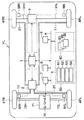
図1は、本実施形態の駐車補助ブレーキ装置の全体構成を示す図である。図中、車両VLの右前輪、左前輪、右後輪、左後輪をそれぞれに対応する構成要素にFR、FL、RR、RLを付して表わしてある。 FIG. 1 is a diagram illustrating an overall configuration of a parking assist brake device according to the present embodiment. In the figure, the front right wheel, the left front wheel, the right rear wheel, and the left rear wheel of the vehicle VL are represented by FR, FL, RR, and RL as components corresponding thereto.
本実施形態の駐車補助ブレーキ装置は、ブレーキ制御ECU1、油圧ブレーキ装置2、電動パーキングブレーキ(以下、PKBという)3、各車輪4FR、4RL、4FL、4RR毎に備えられたホイールシリンダ(以下、W/Cという)41FR、41RL、41FL、車輪速度センサ5FR、5RL、5FL、5RR、車内LANバス6、エンジンECU7、周辺監視制御ECU8、警告表示・警報装置9、各種センサ類50、および制動要求出力部80を備えた構成となっている。
The parking assist brake device according to the present embodiment includes a
これらの構成要素のうち、ブレーキ制御ECU1、エンジン制御ECU7、周辺監視制御ECU8、警告表示・警報装置9、センサ類50、および制動要求出力部80は、それぞれ車内LANバス6に接続され、車内LANバス6を介して互いに信号の送受を行えるようになっている。
Among these components, the
ブレーキ制御ECU1は、車両制動制御手段を構成するもので、コンピュータにより構成されており、車内LANバス6を介して周辺監視制御ECU8や制動要求出力手段80からの制動要求、および各車輪速度センサ5a〜5dおよびセンサ類50からのセンサ信号を入力し、後述する油圧ブレーキ装置2およびPKB3を制御するための駆動信号やエンジン制御ECU7への制御信号を出力する。
The
油圧ブレーキ装置2は、本発明における第1ブレーキ手段を構成するもので、PKB3は、本発明における第2ブレーキ手段を構成するものである。
The
図2は、第1ブレーキ手段である油圧ブレーキ装置2の具体的な配管構成を示した図である。この図を参照して、油圧ブレーキ装置2について説明する。
FIG. 2 is a diagram showing a specific piping configuration of the
マスタシリンダ(以下、M/Cという)10は、運転者により図示しないブレーキペダルが踏み込まれると、センサ類50に含まれる後述するブレーキ操作量センサ53で検出されるブレーキペダルの踏力に応じたM/C圧を発生させる。このM/C10には、第1配管系統11および第2配管系統21が接続されており、これら各配管系統11、21に対して各W/C41FR、41RL、41FL、41RRがダイアゴナル接続されている。
A master cylinder (hereinafter referred to as “M / C”) 10 is configured such that when a brake pedal (not shown) is depressed by a driver, the M corresponding to the depression force of the brake pedal detected by a brake operation amount sensor 53 (described later) included in the
M/C10で発生させられたブレーキ液圧は、それぞれ第1配管系統11および第2配管系統21を介して各車輪に備えられたW/C41FR、41RL及び41FL、41RRに伝達され、第1の制動力を発生するようになっている。
The brake hydraulic pressure generated by the M /
以下では、第1配管系統11、特に、右前輪4FRに関わる配管系統を中心に説明するが、他の車輪および第2配管系統についても同様である。
Hereinafter, the
第1配管系統11には、右前輪4FRおよび左後輪4RLのそれぞれに対して、ABS制御時に各W/C41FR、41RLの増圧および保持を調整する増圧制御弁14a、14bが設けられている。増圧制御弁14a、14bそれぞれに並列に逆止弁141a、141bが設けられ、増圧制御弁14a、14bの遮断時にW/C圧が過剰となった場合に液流をM/C10側へ逃がすようになっている。
The
増圧制御弁14a、14bとW/C41FR、41RLとの間から伸びる減圧管路12にはABS制御におけるW/C41FR、41RLの減圧、保持を調整する減圧制御弁15a、15bが設けられている。この減圧管路12はリザーバ16と接続されている。
Pressure reducing
リザーバ16に貯溜されるブレーキ液はモータ20により駆動されるポンプ17によって汲み上げられたのち、増圧制御弁14a、14bと後述するマスタカット弁(以下、SM弁という)18との間となっている。なお、ポンプ17の吐出口には逆止弁171が設けられ、ポンプ17の吐出口に高いブレーキ液圧が加えられないようになっている。
The brake fluid stored in the
M/C10と増圧制御弁14a、14bとの間には、SM弁18が配置されている。このSM弁18は、非通電時は連通状態、通電時には図示方向の逆止弁による遮断状態となる2位置弁である。SM弁18は、遮断状態のときには、W/C41FR、41RL側の圧が逆止弁のばねによるクラッキング圧分M/C10側の圧よりも高くなったときにリリースされ、圧を逃がす構造となっている。このSM弁18には、並列に逆止弁181が設けられており、M/C10側からW/C41FR、41RL側への流動のみが許容されるようになっている。
An
M/C10とSM弁18との間と、リザーバ16とは吸引管路13で接続されている。
The M /
第1配管系統11のM/C10とSM弁18との間には油圧センサ30が設けられ、M/C10が発生したブレーキ液圧を検出できるようになっている。この油圧センサ30で検出されるブレーキ液圧は、M/C10の図示しないセカンダリ室の発生圧力であるが、第2配管系統が接続されるプライマリ室にも同圧が発生しているので、油圧センサ30により実質的にM/C圧を検出することができる。
A
また、増圧制御弁14a、14bとW/C41FR、41RLとの間にも油圧センサ19a、19bが設けられ、それぞれのW/C圧が検出できるようになっている。
Also,
これら、油圧センサ30および油圧センサ19a、19bの出力信号は、ブレーキ制御ECU1に入力される。
The output signals of the
上記増圧制御弁14a、14b、減圧制御弁15a、15bは2位置弁であり、ブレーキペダルの非操作時および通常ブレーキ時などの非通電(OFF)時には図示の弁体位置、すなわち、増圧制御弁14a、14bは連通状態、減圧制御弁15a、15bは遮断(カット)状態にある。また、SM弁18も通常の非通電時には図示の弁体位置、すなわち連通状態にある。
The pressure-increasing
これら各制御弁は、ブレーキ制御ECU1からの作動信号により駆動される。また、ポンプ17、27を駆動するモータ20もブレーキ制御ECU1からの作動信号により駆動される。
Each of these control valves is driven by an operation signal from the
なお、これらの油圧ブレーキ装置2に対する各作動信号は、総じて第1駆動信号に相当する。また、油圧ブレーキ装置2を制御停止(または、制御禁止)にするとは、第1駆動信号を0(非作動状態)、具体的には、増圧制御弁14a、14b、24a、24b、減圧制御弁15a、15b、25a、25bおよびSM弁18、28を全て非通電とし、かつ、モータ20の駆動電流を0とすることを意味している。したがって、油圧ブレーキ装置2で示される第1ブレーキ手段は、第1駆動信号が解除されると制動力も解除(制動力=0)されることになる。
Each operation signal for the
このように構成される第1ブレーキ手段としての油圧ブレーキ装置2においては、ブレーキ失陥が発生しているか否かを検出する異常チェックが行われる。この異常チェックには、ハード的なものと電気的なもののチェックがある。
In the
ハード的なものの異常チェックは、増圧制御弁14a、14b、24a、24b、減圧制御弁15a、15b、25a、25bおよびSM弁18、28を作動させ、さらにはモータ20を駆動してポンプ17、27を作動させることによって行われる。このときに、これら各ハード構成が正常に作動すれば、異常がないものとされ、作動しなければ異常が検出される。このようなハード的な異常チェックは、例えば、イグニッションスイッチがオンされた直後に行われるイニシャルチェック時や駐車補助ブレーキ制御が実行されるときに行われる。
In the hardware check, the pressure
電気的なものの異常チェックは、ハード的なものの異常チェックを行う際に、各ハード構成を作動させるための制御信号を発生するブレーキ制御ECU1が正常に作動する否かを検出することで行われる。つまり、各ハード構成を作動させるための制御信号が正常に出力されていれば、異常がないものとされ、正常に出力されていなければ異常が検出される。
The electrical abnormality check is performed by detecting whether or not the
この異常チェック時に異常が検出された場合には、ブレーキ制御ECU1に備えられる図示しないメモリの異常検出フラグがセットされることで、ブレーキ失陥が発生したことが確認できるようになっている。
If an abnormality is detected during the abnormality check, an abnormality detection flag in a memory (not shown) provided in the
続いて、この油圧ブレーキ装置2の基本的な制御方法について説明する。
Subsequently, a basic control method of the
運転者によりブレーキペダルが踏み込まれるときの通常のブレーキ操作においては、全ての制御弁(SM弁18、増圧制御弁14a、減圧制御弁15a)は非通電(OFF)状態とされる。このため、M/C圧がそのままW/C41FR、41RLに作用し、W/C圧=M/C圧となる。
In a normal brake operation when the driver depresses the brake pedal, all the control valves (
ABS制御中は、タイヤロックを回避するためにW/C圧を減圧する過程と制動力を回復するためにW/C圧を増圧する過程とでそれぞれ動作が異なる。なお、SM弁18はABS制御中は、通常OFF(連通状態)にするとともに、ポンプ17を駆動してリザーバ16よりブレーキ液を吸引する。
During the ABS control, the operation differs between a process of reducing the W / C pressure in order to avoid tire lock and a process of increasing the W / C pressure in order to recover the braking force. The
まず、ABS制御の減圧過程では、増圧制御弁14aを通電状態(ON)すなわち遮断(カット)状態とし、かつ、減圧制御弁15aをON/OFFのデューティー比制御する。これにより、連通/カットの切換えが繰り返されて、W/C41FRよりブレーキ液が所定の変化勾配でリザーバ16へ流れ出しW/C圧が減圧する。
First, in the depressurization process of the ABS control, the pressure
ABS制御の増圧過程では、減圧制御弁15aを非通電状態(OFF)すなわちカット状態とし、かつ、増圧制御弁14aをOFF/ONのデューティー比制御する。これにより、連通/カットの切換えが繰り返されて、M/C10よりブレーキ液がW/C41FRに供給されてW/C圧は増圧する。
In the pressure increasing process of the ABS control, the pressure reducing
次に、駐車補助ブレーキ制御、すなわち、ブレーキペダルの踏み込み操作の有無に関わらず、周辺監視制御ECU8や制動要求出力手段80からの制動要求信号に基づいて、ブレーキ制御ECU1が油圧ブレーキ装置2に対して指示するブレーキ動作中の増圧過程および減圧過程について説明する。
Next, regardless of whether there is parking assist brake control, that is, whether or not the brake pedal is depressed, the
駐車補助ブレーキ制御の増圧過程では、SM弁18をON(カット状態)に、かつ、減圧制御弁15aをOFF(カット状態)にする。また、ポンプ17を駆動してリザーバ16よりブレーキ液を吸引して吐出圧を発生させた状態で、油圧センサ19aの検出値との比較を行いながら、増圧制御弁14aをOFF/ONのデューティー比制御により所定の変化勾配で、あるいは設定された目標の圧力までW/C圧を増圧する。このとき、必要に応じてM/C10から吸引管路13、リザーバ16を介してブレーキ液がポンプ17の吸引口に補充される。
In the pressure increasing process of the parking assist brake control, the
駐車補助ブレーキ制御の減圧過程では、SM弁18をON(カット状態)に、かつ、増圧制御弁14aをON(カット状態)にするとともに、ポンプ17を駆動してリザーバ16よりブレーキ液を吸引して吐出圧を発生させた状態で、油圧センサ19aの検出値との比較を行いながら、減圧制御弁15aをON/OFFのデューティー比制御により所定の勾配で、あるいは設定された目標の圧力までW/C41FRよりブレーキ液を吸引してW/C圧を減圧する。このとき、増圧制御弁14aおよびSM弁18がともにカット状態であるため、ポンプ17の吐出圧は増大するが、その圧がSM弁18の逆止弁のばねのクラッキング力より大きくなるとリリースされて圧力が低下する。
In the depressurization process of the parking assist brake control, the
次に、第2ブレーキ手段であるPKB3について説明する。 Next, PKB3 which is a 2nd brake means is demonstrated.
PKB3は、ブレーキワイヤ31R、31L後輪4RL、4RRの各ブレーキキャリパと接続されている。このPKB31は、ブレーキ制御ECU1からの第2駆動信号により動作する図示しないモータおよびギア機構からなるアクチュエータが、ブレーキワイヤ31R、31Lを介して左右後輪4RR、4RLのブレーキキャリパを駆動することにより、制動力すなわち、第2の制動力を発生させる。PKB3のモータは、第2駆動信号に基づきデューティー駆動されて正転または逆転させられる。これにより、第2の制動力の大きさが制御されるようになっている。
The PKB 3 is connected to the brake calipers of the
このとき、デューティー比に応じた制動力が発生し、目標の制動力となったらPKB3のモータがロックし、モータロックが検出されるとモータの駆動電流が遮断、すなわち、第2駆動信号が解除されて、PKB3は制御停止(制御禁止)の状態となる。このPKB3の制御停止状態ではギア機構は動かないので、第2の制動力は維持され、ロック状態となる。 At this time, a braking force corresponding to the duty ratio is generated. When the target braking force is reached, the motor of the PKB 3 is locked, and when the motor lock is detected, the driving current of the motor is cut off, that is, the second driving signal is released. Thus, the PKB 3 enters a control stop (control prohibited) state. Since the gear mechanism does not move in the control stop state of PKB3, the second braking force is maintained and the lock state is established.
このPKB3は、駐車補助ブレーキ制御中にブレーキ制御ECU1からの第2駆動信号によって行われる以外に、運転者により図示しないパーキングブレーキスイッチをON/OFF操作した場合にも、その操作信号に基づきブレーキ制御ECU1がPKB3の第2駆動信号を出力することにより駆動されるようになっている。
This PKB3 is not controlled by the second drive signal from the
車輪速度5FL〜5RRセンサは、図2に示すように、各車輪の回転速度を検出できるように、各車輪それぞれに備えられ、それぞれの出力信号が直接ブレーキ制御ECU1に入力されるようになっている。車輪速度センサ5FR、5FL、5RR、5RLには、例えばホール素子による半導体式速度センサが用いられ、低速度でも確実な車輪回転パルスを得ることで、駐車時の速度でも正確な車速が検出できるようになっている。
As shown in FIG. 2, the wheel speeds 5FL to 5RR sensors are provided in the respective wheels so that the rotational speeds of the respective wheels can be detected, and the respective output signals are directly input to the
エンジン制御ECU7は、アクセル操作量センサ52からのアクセル操作量であるアクセル開度信号や、エンジン回転数、水温や排気中の酸素濃度などに基づき走行状態に応じて燃料噴射量を調整してエンジン70へ指令値を与えることによりエンジン出力を制御する。これにより、自動変速機(AT)71および車軸72R、72Lを介して回転駆動される左右の前輪4FR、4FLの駆動力が調整されるようになっている。
The
なお、AT71は、エンジン70の回転を車軸72R、72Lに伝達するトルクコンバータを内蔵した公知の装置であり、図示しない制御装置により変速制御されるものである。本実施形態では、クリープ現象により車両を低速で走行させる(以下、クリープ走行という)状態を積極的に利用して駐車補助ブレーキ制御を行うものであり、AT71の制御に関しては特に関係ないため、AT71の制御装置については説明を省略する。
The
すなわち、本実施形態においては、ブレーキ制御ECU1からのエンジン出力調整信号により、エンジン制御ECU7がアイドル状態からエンジン出力を増加、または、アイドル状態への出力減少を行うことによる駆動力の制御と、ブレーキ制御ECU1による制動力の制御を併用して車両VLを定速モードで走行させるようになっている。
That is, in the present embodiment, the
周辺監視制御ECU8は、周辺監視手段に相当するもので、センサ類50に含まれる後述する障害物センサ54により計測された障害物までの距離xに基づき、車両VLを停止すべき位置までの距離である制動距離Lを算出する。そして、周辺監視制御ECU8は、求めた制動距離Lを制動要求値としてブレーキ制御ECU1へ出力するようになっている。
The surrounding monitoring control ECU 8 corresponds to surrounding monitoring means, and is based on a distance x to an obstacle measured by an obstacle sensor 54 (described later) included in the
警告表示・警報装置9は、ランプやディスプレイ等の警告表示器およびブザーやスピーカ等の警報器を備えたもので、各種制御を実行していること等をランプ点灯やディスプレイ表示、ブザーやスピーカを通じての警告音によってドライバに報知するものである。 The warning display / alarm device 9 is provided with a warning indicator such as a lamp and a display and an alarm device such as a buzzer and a speaker. A warning sound is sent to the driver.
センサ類50には、操舵量センサ51、アクセル操作量センサ52、ブレーキ操作量センサ53および障害物センサ54が含まれている。
The
操舵量センサ51は、ハンドル操舵量を検出するものであり、アクセル操作量センサ52は、アクセルペダルの操作量を検出するものである。ブレーキ操作量センサ53は、ブレーキペダルの操作量を検出するものである。
The
障害物センサ54は、車両VL周辺の障害物を検出するためのもので、車両の前部および後部の例えばバンパに設けられたコーナーソナーにより車両の前方および後方に存在する障害物までの距離xを計測し、その微分信号と共に車内LANバス6を介してブレーキ制御ECU1や他の制動要求出力手段へ送る。距離xの微分信号は、前方または後方の走行車両などの障害物との相対速度に相当する。
The obstacle sensor 54 is for detecting an obstacle around the vehicle VL, and is a distance x to an obstacle existing in the front and rear of the vehicle by corner sonar provided in, for example, a bumper at the front and rear of the vehicle. Is sent to the
制動要求出力部80は、制動要求出力手段に相当するもので、渋滞追従ECU81、車間制御ECU82および居眠り防止ECU83を含んでいる。
The braking
渋滞追従ECU81は、交通渋滞時に前方車両の制動および停車状態を検出し、自車VLの車速より前方車両に追突することなく所定車間距離の位置に停止または車間距離を維持するための目標減速度(たとえば、「0.23G(G:重力加速度)の減速」)を算出する。そして、渋滞追従ECU82は、その算出結果をECU要求値として、車内LANバス6を介してブレーキ制御ECU1へ出力する。
The traffic
これに基づき、ブレーキ制御ECU1では、例えば、減速度1Gが制動圧10MPa(Pa:圧力単位、パスカル)に相当するものとして、ECU要求値として示される減速度を制動圧(制動油圧)に変換し、その大きさを評価するようになっている。
Based on this, the
車間制御ECU82は、前後の車両などの障害物と自車VLとの距離および相対速度を検出し、障害物との車間距離を、予め設定された、あるいは運転者により設定変更された所定値に保つよう、エンジン制御ECU7による駆動制御やブレーキ制御ECU1による制動制御を行うものである。
The inter-vehicle control ECU 82 detects the distance and relative speed between the obstacles such as the front and rear vehicles and the own vehicle VL, and sets the inter-vehicle distance to the obstacle to a predetermined value set in advance or changed by the driver. The drive control by the
さらに、ECU要求値として、ブレーキ制御ECU1へ目標制動距離(たとえば、「28mで停止」)を出力する。また、前後の障害物との距離が急激に小さくなった場合に、車両進行方向への歩行者等の急な飛び出しの可能性があるため、急制動を可能にする制動要求を出す。なお、前後障害物との距離は障害物センサ54により検出される。
Further, a target braking distance (for example, “stop at 28 m”) is output to the
これに基づき、ブレーキ制御ECU1では、現在車速と目標制動距離とから目標減速度を求め、あるいは急制動時の最大減速度の設定を行い、これを、上述と同様制動圧に変換して、大きさを評価するようになっている。
Based on this, the
居眠り防止ECU83は、運転操作状態あるいは運転者の生理状態を検出して運転者の居眠り状態を判定し、運転者に覚醒を促すためにブザーなどの警報や断続的な瞬間制動を行うものであるが、本実施形態においては、ECU要求値として、ブレーキ制御ECU1へ上記覚醒のための目標制動液圧の時間変化値を与える。この制動力の時間変化は、例えば、三角波形状とすることができる。
The dozing prevention ECU 83 detects the driving operation state or the physiological state of the driver, determines the driver's dozing state, and performs an alarm such as a buzzer or intermittent momentary braking to prompt the driver to wake up. However, in this embodiment, the time change value of the target brake hydraulic pressure for awakening is given to the
以上のように本実施形態の駐車補助ブレーキ装置が構成されている。このように構成される駐車補助ブレーキ装置では、図示しない駐車補助ブレーキ制御開始用のスイッチが投入され、上述した駐車補助制御が実行される駐車補助モードが設定されると、駐車補助ブレーキ制御が実行されるようになっている。この駐車補助ブレーキ制御は、駐車補助制御中実行される。具体的には、ブレーキ制御ECU1、エンジン制御ECU7および周辺監視ECU8により、車輪速度センサ5FL〜5RRやW/C圧センサ19a、19b、29a、29bおよびセンサ類50からの検出信号、さらには、制動要求出力部80からECU要求値として出される目標減速度等に基づいて、駐車補助ブレーキ制御およびフェールセーフ制御などの各種制御が実行される。
As described above, the parking assist brake device of the present embodiment is configured. In the parking assist brake device configured as described above, when a parking assist brake control start switch (not shown) is turned on and a parking assist mode in which the above-described parking assist control is executed is set, the parking assist brake control is executed. It has come to be. This parking assistance brake control is executed during parking assistance control. Specifically, the
そして、駐車補助ブレーキ制御が実行されると、車両VLと障害物との距離xが比較的長い場合には、定速モードでの動作によりブレーキ操作量および道路勾配に応じた目標速度(クリープ速度)で車両VLがクリープ走行するように調整され、障害物との距離xが短くなると停車モードでの動作に切り替わり、車速に応じて決められた制動距離となるように制動力が発生させられ、車両VLが減速するように調整される。 When the parking assist brake control is executed, when the distance x between the vehicle VL and the obstacle is relatively long, the target speed (creep speed) corresponding to the brake operation amount and the road gradient is obtained by the operation in the constant speed mode. ) Is adjusted so that the vehicle VL creeps, and when the distance x to the obstacle is shortened, the operation is switched to the operation in the stop mode, and the braking force is generated so that the braking distance determined according to the vehicle speed is obtained. Adjustment is made so that the vehicle VL decelerates.
このような駐車補助ブレーキ制御の詳細に関しては、特開2004−50925号公報等に示されるものと同様であるため、ここでは省略する。 The details of such parking assist brake control are the same as those disclosed in Japanese Patent Application Laid-Open No. 2004-50925 and the like, and are therefore omitted here.
続いて、この駐車補助ブレーキ制御中に実行されるフェールセーフ制御に関して説明する。 Next, the fail safe control executed during the parking assist brake control will be described.
このフェールセーフ制御処理は、駐車補助ブレーキ制御中に、ブレーキ失陥が発生すると、油圧ブレーキ装置2によって制動力を発生させられなくなる可能性があることから、異常チェックによってブレーキ失陥が発生したことが検出された場合には、PKB3によって制動力を発生させるものである。
In this fail-safe control process, if a brake failure occurs during the parking assist brake control, the brake force may not be generated by the
図3は、フェールセーフ制御処理のフローチャートを示したものである。このフローチャートに示されるフェールセーフ制御処理は、ブレーキ制御ECU1において、車両における図示しない駐車補助ブレーキ制御開始用のスイッチがオンされたときに、所定の制御周期毎に実行される。
FIG. 3 shows a flowchart of the fail-safe control process. The fail-safe control process shown in this flowchart is executed every predetermined control period when the
まず、ステップ101では、駐車補助ブレーキ制御中であるか否かが判定される。例えば、駐車補助ブレーキ制御が実行されるときに、ブレーキ制御ECU1内に備えられる図示しないメモリのフラグをセットしておき、そのフラグがセットされているかリセットされているかを確認することで、この判定を行うことができる。
First, in
このステップで肯定判定された場合には、駐車補助ブレーキ制御中であるものとして、ステップ103に進む。 If an affirmative determination is made in this step, it is determined that the parking assist brake control is being performed, and the routine proceeds to step 103.
ステップ103では、ブレーキ失陥が検出されているか否かが判定される。この判定は、上記したように、駐車補助ブレーキ制御が実行されるときに行われた異常チェックによってブレーキ制御ECU1に備えられる図示しないメモリに異常検出フラグがセットされたか否かに基づいて行われる。そして、異常検出フラグがセットされいなければ何ら問題がない。このため、このステップで否定判定された場合には、そのまま処理が終了される。そして、このステップで肯定判定された場合には、ステップ105に進む。
In
ステップ105では、ブレーキ失陥が発生して油圧ブレーキ装置2によって制動力が発生させられない状態になっている可能性があることから、駐車補助ブレーキ制御を終了させるための処理が実行される。これにより、油圧ブレーキ装置2によって制動力を発生させるために出される第1駆動信号が出力されなくなり、駐車補助ブレーキ制御が終了される。
In
続いて、ステップ107に進み、警告処理が実行される。この処理では、警告音およびランプもしくはディスプレイ表示による警告を行うべく、警告表示・警報装置9にフェールセーフ制御が実行されたことを示す制御信号が出力される。これにより、警告表示・警報装置9でランプ点灯やディスプレイ表示や、ブザーやスピーカを通じての警告音での警報が行われ、ドライバにブレーキ失陥が発生し、フェールセーフ制御が実行されることが報知される。 Then, it progresses to step 107 and a warning process is performed. In this process, a warning signal and a control signal indicating that fail-safe control has been executed are output to the warning display / alarm device 9 in order to issue a warning by a lamp or display. As a result, the warning display / alarm device 9 is lit on the lamp, displayed on the display, and an alarm with a warning sound through a buzzer or speaker is performed, and the driver is informed that the brake has failed and the fail-safe control is executed. Is done.
次に、ステップ109で、現在の車速より目標減速度および減速度増加勾配選択が行われる。現在の車速は、例えば、車輪速度センサ5FL〜5RRからの信号に基づいて駐車補助ブレーキ制御中に求められる車速や、他のECUで既に求められている車速が用いられる。減速度増加勾配選択は、予めブレーキ制御ECU1内に設けられた車速に応じた減速度増加勾配マップを利用して行われる。
Next, in
続いて、ステップ111に進み、選択された減速度増加勾配を得るための制御ブレーキ力が演算される。なお、減速度に対する制動圧の換算に関しては、上記と同様である。 Subsequently, the routine proceeds to step 111, where the control brake force for obtaining the selected deceleration increasing gradient is calculated. Note that the conversion of braking pressure to deceleration is the same as described above.
続いて、ステップ113に進み、ドライバが要求する制動力(以下、ドライバ要求制動力という)に対して制御ブレーキ力が大きいか否かが判定される。ここでいうドライバ要求制動力とは、ドライバによるブレーキペダルの踏み込みに応じて発生させられる制動力を意味する。このドライバ要求制動力よりも制御ブレーキ力が大きい場合には、ドライバの要求以上のブレーキ力が必要になっているということであるから、制御ブレーキ力を発生させるべく、ステップ115に進む。逆に、ドライバ要求制動力の方が制御ブレーキ力よりも大きい場合には、ドライバが要求するブレーキ力の方がフェールセーフ制御によって求められるブレーキ力よりも大きいということであるから、ドライバの制動意志を尊重し、ドライバ要求制動力が優先される。この場合、ステップ115を飛び越えてそのまま処理が終了される。 Subsequently, the routine proceeds to step 113, where it is determined whether or not the control braking force is greater than the braking force requested by the driver (hereinafter referred to as driver-requested braking force). The driver-required braking force here means a braking force generated in response to the driver depressing the brake pedal. If the control braking force is greater than the driver required braking force, it means that a braking force greater than the driver's request is required, and the process proceeds to step 115 to generate the control braking force. On the other hand, if the braking force required by the driver is greater than the control braking force, the braking force required by the driver is greater than the braking force required by fail-safe control. The driver's requested braking force is prioritized. In this case, the process skips step 115 and ends as it is.
ステップ115では、制御ブレーキ力を発生させるための強制制動処理が実行される。具体的には、制御ブレーキ力に相当する制動圧が発生させることを指示する第2駆動信号が出力される。これにより、PKB3が発生させる第2の制動力の大きさが調整され、制御ブレーキ力が発生させられる。なお、この強制制動処理が実行されたときには、この処理が実行されたことを示すべく、ブレーキ制御ECU1に備えられる図示しない強制制動フラグがセットされる。
In step 115, a forced braking process for generating a control braking force is executed. Specifically, a second drive signal that instructs to generate a braking pressure corresponding to the control braking force is output. Thereby, the magnitude | size of the 2nd braking force which PKB3 generates is adjusted, and a control braking force is generated. When this forced braking process is executed, a forced braking flag (not shown) provided in the
一方、ステップ101で否定判定された場合には、駐車補助ブレーキ制御が行われていない状態もしくは駐車補助ブレーキ制御が強制的に終了させられた状態であるものとして、ステップ117に進む。
On the other hand, if a negative determination is made in
ステップ117では、強制制動処理が実行された後か否かが判定される。この判定は、上述した強制制動フラグがセットされているか否かに基づいて行われる。そして、強制制動フラグがセットされていればステップ119に進み、リセットされていればそのまま処理が終了される。例えば、駐車補助ブレーキ制御が実行されていない通常走行中や、駐車補助ブレーキ制御中にブレーキ失陥が発生してもドライバのブレーキペダル操作に基づいて発生させられた制動力によって車両VLを停止させた場合には、このステップで否定判定されることになる。
In
ステップ119では、強制制動処理が実行された後に解除操作がなされたか否かが判定される。ここでいう解除操作とは、一定時間、車両VLが停止させること、もしくは、アクセル操作がなされたこと等を意味する。このような解除操作の有無は、車輪速度センサ5FL〜5RRからの検出信号に基づいて、もしくは、アクセル操作量センサ52の検出信号に基づいて判定される。
In
このステップで肯定判定されれば、強制制動フラグをリセットしたのち、ステップ121に進んで強制制動解除処理が実行され、PKB3に発生させられている制動圧を解除すべく、第2駆動信号が解除される。また、このステップで否定判定されれば、そのまま処理が終了される。この場合、強制制動処理で設定されたPKB3に発生させた制動圧が維持されることになる。 If an affirmative determination is made in this step, the forced braking flag is reset, and then the process proceeds to step 121 where a forced braking release process is executed, and the second drive signal is released to release the braking pressure generated in PKB3. Is done. If a negative determination is made in this step, the process is terminated as it is. In this case, the braking pressure generated in the PKB 3 set in the forced braking process is maintained.
以上説明したように、本実施形態の駐車補助ブレーキ装置によれば、駐車補助ブレーキ制御中にブレーキ失陥が発生したときには、車両VLを自動的に停止させるようにしている。これにより、駐車補助ブレーキ制御を実行するにあたり、ブレーキ失陥が検出された場合に、そのブレーキ失陥に対応できるフェールセーフ機能を備えた駐車補助ブレーキ制御装置とすることができる。 As described above, according to the parking assist brake device of this embodiment, the vehicle VL is automatically stopped when a brake failure occurs during the parking assist brake control. Thus, when executing the parking assist brake control, when a brake failure is detected, a parking assist brake control device having a fail-safe function that can cope with the brake failure can be provided.
また、本実施形態のフェールセーフ制御では、車速に応じた減速度増加勾配を選択し、その選択された減速度増加勾配が得られる目標減速度となるように車両VLを減速させて停止させるようにしている。このため、車両VLの停止が急ブレーキにならないようにできる。 Further, in the fail-safe control of the present embodiment, a deceleration increase gradient corresponding to the vehicle speed is selected, and the vehicle VL is decelerated and stopped so that the selected deceleration increase gradient is obtained as a target deceleration. I have to. For this reason, it is possible to prevent the vehicle VL from stopping suddenly.
ただし、ここで選択された減速度増加勾配を得るための制御ブレーキ力よりもドライバ要求制動力の方が大きい場合には、ドライバ要求制動力が得られるようにすることで、ドライバの制動意志を尊重することもできる。 However, if the driver-requested braking force is greater than the control braking force for obtaining the deceleration increase gradient selected here, the driver's braking intention can be increased by ensuring that the driver-requested braking force is obtained. You can respect it.
なお、図3中に示したステップは、各種処理を実行する手段に対応するものである。 Note that the steps shown in FIG. 3 correspond to means for executing various processes.
(第2実施形態)
本発明の第2実施形態について説明する。本実施形態は、第1実施形態に対して、ブレーキ制御ECU1が実行するフェールセーフ制御処理の内容を変更したものであり、駐車補助ブレーキ制御装置の構成などについては第1実施形態と同様であるため、異なる部分についてのみ説明する。
(Second Embodiment)
A second embodiment of the present invention will be described. The present embodiment is different from the first embodiment in the content of fail-safe control processing executed by the
上記第1実施形態では、ブレーキ失陥が発生した場合に、PKB3を用いて強制的に車両VLを停止させるようにしているが、本実施形態では、ブレーキ失陥の形態に応じて、駐車補助ブレーキ制御を継続するか、強制的に車両VLを停止させるかを決め、制御形態を変化させるようにしている。 In the first embodiment, when the brake failure occurs, the vehicle VL is forcibly stopped using the PKB 3, but in this embodiment, parking assistance is performed according to the brake failure mode. Whether to continue the brake control or to forcibly stop the vehicle VL is determined, and the control mode is changed.
図4は、本実施形態の駐車補助ブレーキ制御装置におけるブレーキ制御ECU1が実行するフェールセーフ制御処理のフローチャートを示したものである。
FIG. 4 shows a flowchart of the fail safe control process executed by the
この図に示されるステップ101、103では、第1実施形態で示した図3におけるステップ101、103と同様の処理が実行される。そして、ステップ103でブレーキ失陥が検出された場合に、ステップ201に進み、ブレーキ失陥の内容に応じた制御形態が決められる。すなわち、ステップ201において、ブレーキ失陥は、油圧ブレーキ装置2に備えられる2系統の配管構成のうちのいずれか一方のみに異常が検出されたものなのか、それとも2系統共に異常が検出されたものなのかが判定される。
In
この判定は、例えば、第1実施形態で説明した異常チェック時に異常が検出された場合に、異常検出フラグをセットするのと共に、その異常が検出された対象物を記憶しておき、その対象物が2系統の配管構成のうちのいずれに属するものかをチェックすることにより行われる。 For example, when an abnormality is detected during the abnormality check described in the first embodiment, this determination is performed by setting an abnormality detection flag and storing the object in which the abnormality is detected. Is performed by checking which one of the two systems of piping configurations belongs.
これにより、異常が検出されたのが2系統のうちのいずれか一方であった場合には、ステップ203に進み、ドライバーへの警告処理が行われる。この処理では、警告音およびランプもしくはディスプレイ表示による警告を行うべく、警告表示・警報装置9に油圧ブレーキ装置2に備えられる2系統の配管構成のうちのいずれか一方においてブレーキ失陥が発生したことを示す制御信号が出力される。これにより、警告表示・警報装置9でランプ点灯やディスプレイ表示や、ブザーやスピーカを通じての警告音での警報が行われ、ドライバにブレーキ失陥が発生したことが報知される。
As a result, if the abnormality is detected in any one of the two systems, the process proceeds to step 203 where warning processing for the driver is performed. In this process, a brake failure has occurred in one of the two systems of pipes provided in the
逆に、ステップ201において、2系統共に異常が検出されていた場合には、第1実施形態と同様にステップ105以降の処理が実行される。
On the other hand, if an abnormality is detected in both systems in
また、ステップ101において、駐車補助ブレーキ制御中でなかった場合に関しても、第1実施形態にステップ111以降の処理が実行される。
Moreover, also in the case where the parking assist brake control is not being performed in
以上説明したように、本実施形態では、油圧ブレーキ装置2に備えられる2系統の配管構成のうちのいずれか一方のみに異常が検出されただけの場合には、その旨の警告を行いつつ、駐車補助ブレーキ制御を継続させるようにしている。このため、ドライバにブレーキ失陥が発生したことを知らせつつ、駐車補助ブレーキ制御を継続して実行することが可能となる。
As described above, in the present embodiment, when an abnormality is detected only in one of the two systems of the piping configuration provided in the
なお、駐車補助ブレーキ制御中には、車両VLの車速が低速なクリープ走行とされることから、油圧ブレーキ装置2のうちいずれか一系統のみでしか制動圧を発生させられなくても、十分に車速を減速させることができ、本実施形態のような制御を行っても問題はない。
Note that, during the parking assist brake control, the vehicle VL is creeping at a low speed, so that even if only one of the
(第3実施形態)
本発明の第3実施形態について説明する。本実施形態は、第1実施形態に対して、ブレーキ制御ECU1が実行するフェールセーフ制御処理の内容を変更したものであり、駐車補助ブレーキ制御装置の構成などについては第1実施形態と同様であるため、異なる部分についてのみ説明する。
(Third embodiment)
A third embodiment of the present invention will be described. The present embodiment is different from the first embodiment in the content of fail-safe control processing executed by the
上記第1実施形態では、ブレーキ失陥が発生した場合に、PKB3を用いて強制的に車両VLを停止させるようにしているが、本実施形態では、PKB3を用いて車両VLにおける車速を調整し、駐車補助ブレーキ制御を継続する。 In the first embodiment, when the brake failure occurs, the vehicle VL is forcibly stopped using the PKB 3. In the present embodiment, the vehicle speed in the vehicle VL is adjusted using the PKB 3. Continue parking assist brake control.
図5は、本実施形態の駐車補助ブレーキ制御装置におけるブレーキ制御ECU1が実行するフェールセーフ制御処理のフローチャートを示したものである。
FIG. 5 shows a flowchart of the fail-safe control process executed by the
この図に示されるステップ101、103では、第1実施形態で示した図3におけるステップ101、103と同様の処理が実行される。
In
そして、ステップ103においてブレーキ失陥が発生していると判定された場合には、第1実施形態における図3のステップ105で示した処理を行うことなく、ステップ107に進み、警告処理がなされる。
If it is determined in
この後、ステップ301に進み、クリープ走行が行えるように、駐車補助ブレーキ制御において決められた目標減速度を発生させために必要なPKB3に加える制動力に応じた第2駆動信号が出力される。これにより、PKB3によって車輪4RL、4RRに制動力が発生させられ、駐車補助ブレーキ制御で決められたクリープ走行が実現される。 Thereafter, the process proceeds to step 301 where a second drive signal corresponding to the braking force applied to the PKB 3 necessary for generating the target deceleration determined in the parking assist brake control is output so that creep travel can be performed. As a result, braking force is generated on the wheels 4RL and 4RR by the PKB 3, and the creep running determined by the parking assist brake control is realized.
以上説明したように、本実施形態では、油圧ブレーキ装置2にブレーキ失陥が発生した場合にはPKB3によって制動力を発生さえることで駐車補助ブレーキ制御が継続できるようにしている。このように制動力付与手段として第1ブレーキ手段と第2ブレーキ手段が存在する場合に、通常時に駐車補助ブレーキ制御に用いられる第1ブレーキ手段がブレーキ失陥したとしても第2ブレーキ手段を用いることで、駐車補助ブレーキ制御を継続することが可能である。
As described above, in the present embodiment, when the brake failure occurs in the
(他の実施形態)
上記実施形態では、第1ブレーキ手段を油圧ブレーキ2とし、第2ブレーキ手段をPKB3としているが、自動的に制動力を発生させられるものであれば必ずしもこれらの構成にする必要はない。例えば、電動ブレーキによって第1、第2ブレーキ手段を構成しても良い。さらに、回生ブレーキなどの構成が含まれる場合には、それらと共同して自動的な制動力を発生させるようにしても良い。
(Other embodiments)
In the above-described embodiment, the first brake means is the
また、上記実施形態では、ブレーキ制御ECU1によってフェールセーフ制御処理を実行させるようにしたが、必ずしもブレーキ制御ECU1である必要はない。特に、近年研究が進められている車両における各種制御を統合的に行う統合ECUなどが存在する場合、その統合ECUによってフェールセーフ制御処理を実行させるようにしても良い。また、複数のECUによってフェールセーフ制御処理が実行されるようにしても良い。
In the above embodiment, the fail-safe control process is executed by the
1…ブレーキ制御ECU、2…油圧ブレーキ装置、3…PKB、
4FR、FL、RR、RL…車輪、5FR、FL、RR、RL…車輪速度センサ、
6…車内LANバス、7…エンジン制御ECU、8…周辺監視制御ECU、
9…警告表示・警報装置、50…センサ類、55…ドア開閉センサ、VL…車両。
DESCRIPTION OF
4FR, FL, RR, RL ... wheels, 5FR, FL, RR, RL ... wheel speed sensors,
6 ... In-vehicle LAN bus, 7 ... Engine control ECU, 8 ... Perimeter monitoring control ECU,
9 ... Warning display / alarm device, 50 ... Sensors, 55 ... Door open / close sensor, VL ... Vehicle.
Claims (8)
前記駐車補助ブレーキ制御にあたり、前記車両に備えられる各車輪(4FL、4FR、4RL、4RR)に、ドライバの意思とは無関係に前記制動力を付与可能な第1ブレーキ手段(2)の異常状態を示す検出信号を受け取り、前記第1ブレーキ手段に異常が発生したことを検出する異常検出手段(103)と、
前記異常検出手段によって、前記第1ブレーキ手段に異常が発生したことが検出された場合に、前記車両に備えられる車輪に制動力を付与する前記第1ブレーキ手段とは異なる第2ブレーキ手段(3)に指示信号を出力し、制動力を発生させることで、前記車両を所定速度で走行させるもしくは停止させる車両制動制御手段(115)と、を備えていることを特徴とする駐車補助ブレーキ制御装置。 In a parking assistance brake control device that executes parking assistance brake control for controlling the speed of the vehicle with a braking force when a parking assistance mode for assisting parking of the vehicle (VL) is set for the driver,
In the parking assist brake control, the abnormal state of the first brake means (2) that can apply the braking force to each wheel (4FL, 4FR, 4RL, 4RR) provided in the vehicle regardless of the driver's intention. An abnormality detection means (103) for receiving a detection signal indicating and detecting that an abnormality has occurred in the first brake means;
When the abnormality detecting means detects that an abnormality has occurred in the first brake means, a second brake means (3 different from the first brake means for applying a braking force to a wheel provided in the vehicle is provided. And a vehicle braking control means (115) for causing the vehicle to travel or stop at a predetermined speed by generating an instruction signal and generating a braking force. .
前記車両制動制御手段は、前記第2ブレーキ手段が前記車輪に付加する制動力を制御して前記目標減速度検出手段によって求められた前記目標減速度が得られるように、前記指示信号を出力し、前記第2ブレーキ手段が前記車輪に付与する制動力を調整することを特徴とする請求項1に記載の駐車補助ブレーキ制御装置。 Receiving a data indicating the vehicle speed of the vehicle, and having a target deceleration detecting means (109) for obtaining a target deceleration based on the data indicating the vehicle speed;
The vehicle braking control means outputs the instruction signal so as to obtain the target deceleration obtained by the target deceleration detecting means by controlling the braking force applied to the wheel by the second brake means. The parking assist brake control device according to claim 1, wherein the second brake means adjusts a braking force applied to the wheel.
前記車両制動制御手段は、前記第2ブレーキ手段が前記車輪に付加する制動力を制御して前記減速度増加勾配検出手段によって求められた前記減速度増加勾配が得られるように、前記指示信号を出力し、前記第2ブレーキ手段が前記車輪に付与する制動力を調整することを特徴とする請求項1または2に記載の駐車補助ブレーキ制御装置。 Deceleration increasing gradient detecting means (109) which receives data indicating the vehicle speed of the vehicle and obtains a deceleration increasing gradient based on the data indicating the vehicle speed;
The vehicle braking control means controls the braking force applied to the wheel by the second brake means so as to obtain the deceleration increasing gradient determined by the deceleration increasing gradient detecting means. The parking assist brake control device according to claim 1 or 2, wherein the parking assist brake control device outputs and adjusts a braking force applied to the wheel by the second brake means.
前記車両制動制御手段は、前記第1ブレーキ手段の異常が発生した場所が2系統のうちのいずれか1系統のみであった場合には、前記前記第2ブレーキ手段に指示信号を出力せず、前記第1ブレーキ手段によって制動力を発生させることを特徴とする請求項4に記載の駐車補助ブレーキ制御装置。 In the case where the first brake means is configured to add the braking force by dividing the wheel provided in the vehicle into two systems,
The vehicle braking control means does not output an instruction signal to the second brake means when the location where the abnormality of the first brake means occurs is only one of the two systems. The parking assist brake control device according to claim 4, wherein a braking force is generated by the first brake means.
前記車両に備えられる車輪(4FL、4FR、4RL、4RR)に、ドライバの意思とは無関係に前記制動力を付与する第1ブレーキ手段(2)の異常状態を示す検出信号を受け取り、前記第1ブレーキ手段に異常が発生したことを検出する異常検出機能と、
前記異常検出手段によって、前記第1ブレーキ手段に異常が発生したことが検出された場合に、前記車両に備えられる各車輪(4FL、4FR、4RL、4RR)に制動力を付与する前記第1ブレーキ手段とは異なる第2ブレーキ手段(3)に指示信号を出力し、制動力を発生させることで、前記車両を所定速度で走行させるもしくは停止させる車両制動制御機能と、を備えていることを特徴とする駐車補助ブレーキ制御プログラム。
A parking assistance brake control program for causing a computer to execute a function of controlling the speed of the vehicle with a braking force when a parking assistance mode for assisting the driver in parking the vehicle (VL) is set. ,
A detection signal indicating an abnormal state of the first brake means (2) for applying the braking force to the wheels (4FL, 4FR, 4RL, 4RR) provided in the vehicle regardless of the driver's intention is received, and the first An abnormality detection function for detecting that an abnormality has occurred in the brake means;
The first brake that applies a braking force to each wheel (4FL, 4FR, 4RL, 4RR) provided in the vehicle when the abnormality detecting means detects that an abnormality has occurred in the first brake means. A vehicle braking control function for outputting an instruction signal to a second brake means (3) different from the means and generating a braking force to cause the vehicle to run or stop at a predetermined speed. A parking assistance brake control program.
Priority Applications (2)
| Application Number | Priority Date | Filing Date | Title |
|---|---|---|---|
| JP2004163067A JP2005343248A (en) | 2004-06-01 | 2004-06-01 | Parking assist brake controlling device |
| US11/137,397 US7344205B2 (en) | 2004-06-01 | 2005-05-26 | Parking assist control apparatus and storage medium for parking assist control program |
Applications Claiming Priority (1)
| Application Number | Priority Date | Filing Date | Title |
|---|---|---|---|
| JP2004163067A JP2005343248A (en) | 2004-06-01 | 2004-06-01 | Parking assist brake controlling device |
Publications (1)
| Publication Number | Publication Date |
|---|---|
| JP2005343248A true JP2005343248A (en) | 2005-12-15 |
Family
ID=35496029
Family Applications (1)
| Application Number | Title | Priority Date | Filing Date |
|---|---|---|---|
| JP2004163067A Pending JP2005343248A (en) | 2004-06-01 | 2004-06-01 | Parking assist brake controlling device |
Country Status (1)
| Country | Link |
|---|---|
| JP (1) | JP2005343248A (en) |
Cited By (9)
| Publication number | Priority date | Publication date | Assignee | Title |
|---|---|---|---|---|
| JP2007196714A (en) * | 2006-01-23 | 2007-08-09 | Toyota Motor Corp | Traveling control device for vehicle |
| JP2008137442A (en) * | 2006-11-30 | 2008-06-19 | Toyota Motor Corp | Traveling controller |
| JP2009539676A (en) * | 2006-10-17 | 2009-11-19 | ロベルト・ボッシュ・ゲゼルシャフト・ミト・ベシュレンクテル・ハフツング | Method and system for protecting parking assistance system |
| WO2013047599A1 (en) * | 2011-09-27 | 2013-04-04 | 株式会社アドヴィックス | Parking brake control apparatus |
| JP2016159829A (en) * | 2015-03-04 | 2016-09-05 | 富士重工業株式会社 | Vehicular brake equipment |
| WO2018062097A1 (en) * | 2016-09-28 | 2018-04-05 | 日立オートモティブシステムズ株式会社 | Electric brake device |
| WO2018216054A1 (en) * | 2017-05-22 | 2018-11-29 | 日産自動車株式会社 | Automatic parking control method and automatic parking control apparatus for vehicles |
| CN111267802A (en) * | 2020-03-11 | 2020-06-12 | 三一专用汽车有限责任公司 | Vehicle control method, vehicle control system and automobile |
| CN114670794A (en) * | 2021-01-29 | 2022-06-28 | 北京新能源汽车股份有限公司 | Parking control method and device and electric automobile |
Citations (6)
| Publication number | Priority date | Publication date | Assignee | Title |
|---|---|---|---|---|
| JPH10310040A (en) * | 1997-05-09 | 1998-11-24 | Toyota Motor Corp | Braking device |
| JPH1111274A (en) * | 1997-06-20 | 1999-01-19 | Fujitsu Ten Ltd | Automatic braking device for vehicle |
| JP2001018770A (en) * | 1999-07-07 | 2001-01-23 | Honda Motor Co Ltd | Automatic steering device for vehicle |
| JP2001247025A (en) * | 2000-03-03 | 2001-09-11 | Toyota Motor Corp | Vehicle braking system and multi-system braking system |
| JP2004034746A (en) * | 2002-06-28 | 2004-02-05 | Toyota Motor Corp | Traveling control device for vehicle |
| JP2004050925A (en) * | 2002-07-18 | 2004-02-19 | Advics:Kk | Parking auxiliary brake device |
-
2004
- 2004-06-01 JP JP2004163067A patent/JP2005343248A/en active Pending
Patent Citations (6)
| Publication number | Priority date | Publication date | Assignee | Title |
|---|---|---|---|---|
| JPH10310040A (en) * | 1997-05-09 | 1998-11-24 | Toyota Motor Corp | Braking device |
| JPH1111274A (en) * | 1997-06-20 | 1999-01-19 | Fujitsu Ten Ltd | Automatic braking device for vehicle |
| JP2001018770A (en) * | 1999-07-07 | 2001-01-23 | Honda Motor Co Ltd | Automatic steering device for vehicle |
| JP2001247025A (en) * | 2000-03-03 | 2001-09-11 | Toyota Motor Corp | Vehicle braking system and multi-system braking system |
| JP2004034746A (en) * | 2002-06-28 | 2004-02-05 | Toyota Motor Corp | Traveling control device for vehicle |
| JP2004050925A (en) * | 2002-07-18 | 2004-02-19 | Advics:Kk | Parking auxiliary brake device |
Cited By (15)
| Publication number | Priority date | Publication date | Assignee | Title |
|---|---|---|---|---|
| JP2007196714A (en) * | 2006-01-23 | 2007-08-09 | Toyota Motor Corp | Traveling control device for vehicle |
| US9511756B2 (en) | 2006-10-17 | 2016-12-06 | Robert Bosch Gmbh | Failsafe parking assistance system |
| JP2009539676A (en) * | 2006-10-17 | 2009-11-19 | ロベルト・ボッシュ・ゲゼルシャフト・ミト・ベシュレンクテル・ハフツング | Method and system for protecting parking assistance system |
| JP2012096793A (en) * | 2006-10-17 | 2012-05-24 | Robert Bosch Gmbh | Method and system for protecting parking support system |
| JP2008137442A (en) * | 2006-11-30 | 2008-06-19 | Toyota Motor Corp | Traveling controller |
| WO2013047599A1 (en) * | 2011-09-27 | 2013-04-04 | 株式会社アドヴィックス | Parking brake control apparatus |
| JP2013071521A (en) * | 2011-09-27 | 2013-04-22 | Advics Co Ltd | Parking brake control apparatus |
| JP2016159829A (en) * | 2015-03-04 | 2016-09-05 | 富士重工業株式会社 | Vehicular brake equipment |
| WO2018062097A1 (en) * | 2016-09-28 | 2018-04-05 | 日立オートモティブシステムズ株式会社 | Electric brake device |
| JPWO2018062097A1 (en) * | 2016-09-28 | 2019-02-28 | 日立オートモティブシステムズ株式会社 | Electric brake device |
| WO2018216054A1 (en) * | 2017-05-22 | 2018-11-29 | 日産自動車株式会社 | Automatic parking control method and automatic parking control apparatus for vehicles |
| RU2729143C1 (en) * | 2017-05-22 | 2020-08-04 | Ниссан Мотор Ко., Лтд. | Automatic parking control method and automatic parking control device for vehicles |
| US11292440B2 (en) | 2017-05-22 | 2022-04-05 | Nissan Motor Co., Ltd. | Automatic parking control method and automatic parking control apparatus for vehicles |
| CN111267802A (en) * | 2020-03-11 | 2020-06-12 | 三一专用汽车有限责任公司 | Vehicle control method, vehicle control system and automobile |
| CN114670794A (en) * | 2021-01-29 | 2022-06-28 | 北京新能源汽车股份有限公司 | Parking control method and device and electric automobile |
Similar Documents
| Publication | Publication Date | Title |
|---|---|---|
| JP4470592B2 (en) | Parking auxiliary control device | |
| JP4882302B2 (en) | Parking assistance control device and parking assistance control system | |
| US7344205B2 (en) | Parking assist control apparatus and storage medium for parking assist control program | |
| JP4618035B2 (en) | Vehicle travel control device | |
| JP4862516B2 (en) | Vehicle deceleration control device | |
| JP4214764B2 (en) | Electric parking brake device | |
| US20150066326A1 (en) | Brake System, Brake Apparatus, and Method for Controlling Brake System | |
| US20130138316A1 (en) | Brake Control Apparatus | |
| JP2005035535A (en) | Low speed collision avoidance system for vehicle | |
| JP2004050925A (en) | Parking auxiliary brake device | |
| JP6384503B2 (en) | Vehicle control device | |
| JP2007296950A (en) | Drive support control device | |
| JP2011166996A (en) | Apparatus and method for control of motor-driven vehicle | |
| US10266161B2 (en) | Vehicle brake system | |
| JP2010018193A (en) | Brake control device | |
| JP2010120601A (en) | Vehicle brake control apparatus | |
| JP2005343248A (en) | Parking assist brake controlling device | |
| JP4613520B2 (en) | Parking assistance control device, parking assistance control system, and parking assistance program | |
| JP2004058937A (en) | Vehicle stopping and holding device | |
| JP2008162456A (en) | Automatic braking device | |
| JP2013075542A (en) | Vehicle antitheft control system | |
| JP2008184157A (en) | Automatic brake device | |
| JP6287244B2 (en) | Brake control device for vehicle | |
| JP2012214190A (en) | Braking power control system | |
| US10315633B2 (en) | Vehicle behavior control device |
Legal Events
| Date | Code | Title | Description |
|---|---|---|---|
| A621 | Written request for application examination |
Free format text: JAPANESE INTERMEDIATE CODE: A621 Effective date: 20070130 |
|
| A977 | Report on retrieval |
Free format text: JAPANESE INTERMEDIATE CODE: A971007 Effective date: 20081113 |
|
| A131 | Notification of reasons for refusal |
Free format text: JAPANESE INTERMEDIATE CODE: A131 Effective date: 20081118 |
|
| A521 | Written amendment |
Free format text: JAPANESE INTERMEDIATE CODE: A523 Effective date: 20090113 |
|
| A131 | Notification of reasons for refusal |
Free format text: JAPANESE INTERMEDIATE CODE: A131 Effective date: 20090303 |
|
| A521 | Written amendment |
Free format text: JAPANESE INTERMEDIATE CODE: A523 Effective date: 20090428 |
|
| A02 | Decision of refusal |
Free format text: JAPANESE INTERMEDIATE CODE: A02 Effective date: 20100112 |
|
| A521 | Written amendment |
Free format text: JAPANESE INTERMEDIATE CODE: A523 Effective date: 20100412 |
|
| A911 | Transfer of reconsideration by examiner before appeal (zenchi) |
Free format text: JAPANESE INTERMEDIATE CODE: A911 Effective date: 20100420 |
|
| A912 | Removal of reconsideration by examiner before appeal (zenchi) |
Free format text: JAPANESE INTERMEDIATE CODE: A912 Effective date: 20100618 |