JP6122513B2 - Automotive headlight lighting system - Google Patents
Automotive headlight lighting system Download PDFInfo
- Publication number
- JP6122513B2 JP6122513B2 JP2015559394A JP2015559394A JP6122513B2 JP 6122513 B2 JP6122513 B2 JP 6122513B2 JP 2015559394 A JP2015559394 A JP 2015559394A JP 2015559394 A JP2015559394 A JP 2015559394A JP 6122513 B2 JP6122513 B2 JP 6122513B2
- Authority
- JP
- Japan
- Prior art keywords
- light source
- support
- reflector
- reflectors
- lighting device
- Prior art date
- Legal status (The legal status is an assumption and is not a legal conclusion. Google has not performed a legal analysis and makes no representation as to the accuracy of the status listed.)
- Active
Links
- 238000009826 distribution Methods 0.000 claims description 33
- 238000001816 cooling Methods 0.000 claims description 17
- 238000005286 illumination Methods 0.000 claims description 17
- 230000008878 coupling Effects 0.000 claims description 15
- 238000010168 coupling process Methods 0.000 claims description 15
- 238000005859 coupling reaction Methods 0.000 claims description 15
- 230000000694 effects Effects 0.000 description 4
- 238000000034 method Methods 0.000 description 4
- 230000008569 process Effects 0.000 description 4
- 230000003287 optical effect Effects 0.000 description 3
- 239000000758 substrate Substances 0.000 description 3
- 230000008901 benefit Effects 0.000 description 2
- 230000008859 change Effects 0.000 description 2
- 230000001627 detrimental effect Effects 0.000 description 2
- 229910052751 metal Inorganic materials 0.000 description 2
- 239000002184 metal Substances 0.000 description 2
- 230000009467 reduction Effects 0.000 description 2
- 229910052782 aluminium Inorganic materials 0.000 description 1
- XAGFODPZIPBFFR-UHFFFAOYSA-N aluminium Chemical compound [Al] XAGFODPZIPBFFR-UHFFFAOYSA-N 0.000 description 1
- 238000010276 construction Methods 0.000 description 1
- 238000005520 cutting process Methods 0.000 description 1
- 238000004519 manufacturing process Methods 0.000 description 1
- 238000003801 milling Methods 0.000 description 1
- 238000000465 moulding Methods 0.000 description 1
- 238000010079 rubber tapping Methods 0.000 description 1
- 239000007787 solid Substances 0.000 description 1
Images


Classifications
-
- F—MECHANICAL ENGINEERING; LIGHTING; HEATING; WEAPONS; BLASTING
- F21—LIGHTING
- F21S—NON-PORTABLE LIGHTING DEVICES; SYSTEMS THEREOF; VEHICLE LIGHTING DEVICES SPECIALLY ADAPTED FOR VEHICLE EXTERIORS
- F21S41/00—Illuminating devices specially adapted for vehicle exteriors, e.g. headlamps
- F21S41/10—Illuminating devices specially adapted for vehicle exteriors, e.g. headlamps characterised by the light source
- F21S41/19—Attachment of light sources or lamp holders
- F21S41/192—Details of lamp holders, terminals or connectors
-
- F—MECHANICAL ENGINEERING; LIGHTING; HEATING; WEAPONS; BLASTING
- F21—LIGHTING
- F21S—NON-PORTABLE LIGHTING DEVICES; SYSTEMS THEREOF; VEHICLE LIGHTING DEVICES SPECIALLY ADAPTED FOR VEHICLE EXTERIORS
- F21S41/00—Illuminating devices specially adapted for vehicle exteriors, e.g. headlamps
- F21S41/10—Illuminating devices specially adapted for vehicle exteriors, e.g. headlamps characterised by the light source
- F21S41/14—Illuminating devices specially adapted for vehicle exteriors, e.g. headlamps characterised by the light source characterised by the type of light source
- F21S41/141—Light emitting diodes [LED]
- F21S41/147—Light emitting diodes [LED] the main emission direction of the LED being angled to the optical axis of the illuminating device
- F21S41/148—Light emitting diodes [LED] the main emission direction of the LED being angled to the optical axis of the illuminating device the main emission direction of the LED being perpendicular to the optical axis
-
- F—MECHANICAL ENGINEERING; LIGHTING; HEATING; WEAPONS; BLASTING
- F21—LIGHTING
- F21S—NON-PORTABLE LIGHTING DEVICES; SYSTEMS THEREOF; VEHICLE LIGHTING DEVICES SPECIALLY ADAPTED FOR VEHICLE EXTERIORS
- F21S41/00—Illuminating devices specially adapted for vehicle exteriors, e.g. headlamps
- F21S41/10—Illuminating devices specially adapted for vehicle exteriors, e.g. headlamps characterised by the light source
- F21S41/14—Illuminating devices specially adapted for vehicle exteriors, e.g. headlamps characterised by the light source characterised by the type of light source
- F21S41/141—Light emitting diodes [LED]
- F21S41/151—Light emitting diodes [LED] arranged in one or more lines
-
- F—MECHANICAL ENGINEERING; LIGHTING; HEATING; WEAPONS; BLASTING
- F21—LIGHTING
- F21S—NON-PORTABLE LIGHTING DEVICES; SYSTEMS THEREOF; VEHICLE LIGHTING DEVICES SPECIALLY ADAPTED FOR VEHICLE EXTERIORS
- F21S41/00—Illuminating devices specially adapted for vehicle exteriors, e.g. headlamps
- F21S41/10—Illuminating devices specially adapted for vehicle exteriors, e.g. headlamps characterised by the light source
- F21S41/19—Attachment of light sources or lamp holders
-
- F—MECHANICAL ENGINEERING; LIGHTING; HEATING; WEAPONS; BLASTING
- F21—LIGHTING
- F21S—NON-PORTABLE LIGHTING DEVICES; SYSTEMS THEREOF; VEHICLE LIGHTING DEVICES SPECIALLY ADAPTED FOR VEHICLE EXTERIORS
- F21S41/00—Illuminating devices specially adapted for vehicle exteriors, e.g. headlamps
- F21S41/30—Illuminating devices specially adapted for vehicle exteriors, e.g. headlamps characterised by reflectors
- F21S41/32—Optical layout thereof
- F21S41/33—Multi-surface reflectors, e.g. reflectors with facets or reflectors with portions of different curvature
- F21S41/331—Multi-surface reflectors, e.g. reflectors with facets or reflectors with portions of different curvature the reflector consisting of complete annular areas
- F21S41/333—Multi-surface reflectors, e.g. reflectors with facets or reflectors with portions of different curvature the reflector consisting of complete annular areas with discontinuity at the junction between adjacent areas
-
- F—MECHANICAL ENGINEERING; LIGHTING; HEATING; WEAPONS; BLASTING
- F21—LIGHTING
- F21S—NON-PORTABLE LIGHTING DEVICES; SYSTEMS THEREOF; VEHICLE LIGHTING DEVICES SPECIALLY ADAPTED FOR VEHICLE EXTERIORS
- F21S41/00—Illuminating devices specially adapted for vehicle exteriors, e.g. headlamps
- F21S41/30—Illuminating devices specially adapted for vehicle exteriors, e.g. headlamps characterised by reflectors
- F21S41/32—Optical layout thereof
- F21S41/33—Multi-surface reflectors, e.g. reflectors with facets or reflectors with portions of different curvature
- F21S41/334—Multi-surface reflectors, e.g. reflectors with facets or reflectors with portions of different curvature the reflector consisting of patch like sectors
- F21S41/336—Multi-surface reflectors, e.g. reflectors with facets or reflectors with portions of different curvature the reflector consisting of patch like sectors with discontinuity at the junction between adjacent areas
-
- F—MECHANICAL ENGINEERING; LIGHTING; HEATING; WEAPONS; BLASTING
- F21—LIGHTING
- F21S—NON-PORTABLE LIGHTING DEVICES; SYSTEMS THEREOF; VEHICLE LIGHTING DEVICES SPECIALLY ADAPTED FOR VEHICLE EXTERIORS
- F21S41/00—Illuminating devices specially adapted for vehicle exteriors, e.g. headlamps
- F21S41/30—Illuminating devices specially adapted for vehicle exteriors, e.g. headlamps characterised by reflectors
- F21S41/32—Optical layout thereof
- F21S41/36—Combinations of two or more separate reflectors
-
- F—MECHANICAL ENGINEERING; LIGHTING; HEATING; WEAPONS; BLASTING
- F21—LIGHTING
- F21S—NON-PORTABLE LIGHTING DEVICES; SYSTEMS THEREOF; VEHICLE LIGHTING DEVICES SPECIALLY ADAPTED FOR VEHICLE EXTERIORS
- F21S41/00—Illuminating devices specially adapted for vehicle exteriors, e.g. headlamps
- F21S41/30—Illuminating devices specially adapted for vehicle exteriors, e.g. headlamps characterised by reflectors
- F21S41/39—Attachment thereof
-
- F—MECHANICAL ENGINEERING; LIGHTING; HEATING; WEAPONS; BLASTING
- F21—LIGHTING
- F21S—NON-PORTABLE LIGHTING DEVICES; SYSTEMS THEREOF; VEHICLE LIGHTING DEVICES SPECIALLY ADAPTED FOR VEHICLE EXTERIORS
- F21S41/00—Illuminating devices specially adapted for vehicle exteriors, e.g. headlamps
- F21S41/60—Illuminating devices specially adapted for vehicle exteriors, e.g. headlamps characterised by a variable light distribution
- F21S41/65—Illuminating devices specially adapted for vehicle exteriors, e.g. headlamps characterised by a variable light distribution by acting on light sources
- F21S41/663—Illuminating devices specially adapted for vehicle exteriors, e.g. headlamps characterised by a variable light distribution by acting on light sources by switching light sources
-
- F—MECHANICAL ENGINEERING; LIGHTING; HEATING; WEAPONS; BLASTING
- F21—LIGHTING
- F21S—NON-PORTABLE LIGHTING DEVICES; SYSTEMS THEREOF; VEHICLE LIGHTING DEVICES SPECIALLY ADAPTED FOR VEHICLE EXTERIORS
- F21S45/00—Arrangements within vehicle lighting devices specially adapted for vehicle exteriors, for purposes other than emission or distribution of light
- F21S45/40—Cooling of lighting devices
- F21S45/47—Passive cooling, e.g. using fins, thermal conductive elements or openings
-
- F—MECHANICAL ENGINEERING; LIGHTING; HEATING; WEAPONS; BLASTING
- F21—LIGHTING
- F21S—NON-PORTABLE LIGHTING DEVICES; SYSTEMS THEREOF; VEHICLE LIGHTING DEVICES SPECIALLY ADAPTED FOR VEHICLE EXTERIORS
- F21S41/00—Illuminating devices specially adapted for vehicle exteriors, e.g. headlamps
- F21S41/10—Illuminating devices specially adapted for vehicle exteriors, e.g. headlamps characterised by the light source
- F21S41/14—Illuminating devices specially adapted for vehicle exteriors, e.g. headlamps characterised by the light source characterised by the type of light source
- F21S41/141—Light emitting diodes [LED]
- F21S41/147—Light emitting diodes [LED] the main emission direction of the LED being angled to the optical axis of the illuminating device
Landscapes
- Engineering & Computer Science (AREA)
- General Engineering & Computer Science (AREA)
- Physics & Mathematics (AREA)
- Microelectronics & Electronic Packaging (AREA)
- Optics & Photonics (AREA)
- Non-Portable Lighting Devices Or Systems Thereof (AREA)
Description
本発明は、自動車ヘッドライト用照明装置に関し、とりわけ、照明装置が少なくとも1つのリフレクタを有し、少なくとも1つのリフレクタに少なくとも1つの光源が割り当てられ、少なくとも1つの光源からの光が配光ないし配光の一部を形成するためにリフレクタによって照明装置の前方の領域に放射されるものに関する。 The present invention relates to a lighting device for an automobile headlight, and in particular, the lighting device has at least one reflector, and at least one light source is assigned to at least one reflector, and light from at least one light source is distributed or distributed. It relates to what is emitted by the reflector to the area in front of the luminaire to form part of the light.
更に、本発明は、少なくとも1つのそのような照明装置を有する自動車用ヘッドライトに関する。 The invention further relates to an automotive headlight having at least one such lighting device.
自動車用ヘッドライト構造においては、例えばハイビーム配光、減光された配光(例えばロービーム等)のような主配光の生成のために、1又は複数の発光ダイオードから構成されるLED光源がますます多く使用されている。この場合、通常、1又は複数のLED光源からの光は、1又は複数のリフレクタによって、自動車用ヘッドライトが組み込まれている自動車の前方の領域に放射され、該自動車の前方の領域を照明する。 In automotive headlight structures, there are LED light sources consisting of one or more light-emitting diodes for the generation of main light distribution, for example high beam light distribution, dimmed light distribution (eg low beam etc.) More and more are used. In this case, light from one or more LED light sources is usually radiated by one or more reflectors to an area in front of the automobile in which the automobile headlight is incorporated, and illuminates the area in front of the automobile. .
適法な配光を実現可能にするためには、リフレクタと(1又は複数の)割り当てられた光源(割当て光源)が互いに対し正確に位置付けられることが重要である。とりわけLED光源を使用する場合、この問題は更に重要性が大きい。なぜなら、この場合、目標位置から比較的僅かにずれただけで、光像に不所望の及び/又は許容できない効果ないし結果が生じ得るからである。 In order to be able to achieve a legitimate light distribution, it is important that the reflector and the assigned light source (s) (assigned light source) are accurately positioned relative to each other. This problem is even more important especially when LED light sources are used. This is because, in this case, a relatively slight deviation from the target position can cause undesirable and / or unacceptable effects or results in the optical image.
通常は、(1又は複数の)LED光源は、支持体に、一般的には冷却体に配置される。この場合、(1又は複数の)LED光源は、同様に支持体に配置されているLED基板(LED-Platine)に載置され、例えばこの基板に接合されている。関連するリフレクタは相応に位置付けられ、次いで、支持体にないし支持体に関して固定され、一般的にはこの支持体又は他の定置的な構造要素に螺着される。 Usually, the LED light source (s) is placed on a support, typically a cooling body. In this case, the LED light source (s) is mounted on an LED substrate (LED-Platine) that is also disposed on the support, and is bonded to the substrate, for example. The associated reflector is positioned accordingly and then fixed to or with respect to the support and is generally screwed onto this support or other stationary structural element.
しかしながら、この場合、固定プロセスによって、とりわけリフレクタのネジ固定及びその際に生じる力によって、リフレクタに歪みが生じ得ることないしは固定プロセスの際に一般的にリフレクタの適正位置からの意図しないずれが生じることが、しばしば生じている。これは、目的とする光像に対し不利な効果ないし影響を及ぼし、部分的には、光像が最早法定の要求に対応しないという結果をもたらす。 However, in this case, the fixing process, in particular the screw fixing of the reflector and the forces that occur, can cause the reflector to be distorted or generally cause an unintentional deviation from the correct position of the reflector during the fixing process. Often occurs. This has a detrimental effect or influence on the intended optical image, and in part results in the optical image no longer meeting statutory requirements.
それゆえ、本発明の課題は、リフレクタ及び割り当てられた1又は複数の光源の信頼性のある調節が簡単な態様で可能であると共に、上述の欠点が解消されている、照明装置ないし自動車用ヘッドライトを提供することである。 It is therefore an object of the present invention to provide a lighting device or vehicle head in which a reliable adjustment of the reflector and the assigned light source (s) is possible in a simple manner and the above-mentioned drawbacks are eliminated. Is to provide light.
上記の課題を解決するために、本発明により、冒頭に記載した照明装置ないし少なくとも1つのそのような照明装置を有する自動車用ヘッドライトが提供される。該照明装置は、少なくとも1つの、有利にはただ1つの(丁度ないし正確に(genau)1つの)リフレクタ支持体を有し、少なくとも1つのリフレクタは少なくとも1つのリフレクタ支持体に固定的に結合されており、少なくとも1つの光源は少なくとも1つの光源支持体に配設されており、少なくとも1つの光源支持体はリフレクタ支持体に摺動可能に支持されかつ該リフレクタ支持体に関し定められた位置に固定可能である。 In order to solve the above problems, the present invention provides a lighting device as described at the outset or an automotive headlight having at least one such lighting device. The illuminating device has at least one, preferably only one (just or exactly one) reflector support, the at least one reflector being fixedly coupled to the at least one reflector support. And at least one light source is disposed on the at least one light source support, the at least one light source support is slidably supported on the reflector support and fixed in a predetermined position with respect to the reflector support. Is possible.
本発明に応じ、最早、リフレクタは定置的な光源に関して(に対して)配置されるのではなく、最初に、リフレクタが堅固に構成可能なリフレクタ支持体に結合され、次いで、光源支持体に載置された光源が相応に位置付けられ、最後に、光源支持体がリフレクタ支持体に関して(に対して)固定される。説明の単純化のために、ここでは常に単数形(リフレクタ、光源等)を用いるが、複数のリフレクタ、複数の光源、複数の光源支持体等についても適用可能であることは当業者であれば理解できる。 In accordance with the present invention, the reflector is no longer arranged with respect to the stationary light source, but first the reflector is coupled to a rigidly configurable reflector support and then mounted on the light source support. The placed light source is positioned accordingly, and finally the light source support is fixed with respect to the reflector support. In order to simplify the description, the singular form (reflector, light source, etc.) is always used here, but those skilled in the art can also apply to a plurality of reflectors, a plurality of light sources, a plurality of light source supports, etc. Understandable.
リフレクタ支持体も光源支持体も堅固な構造体として構成可能であること、ないしは有利には堅固に構成されていることによって、これらの構造体を互いに対し固定する際に、光像に対する不利な効果(影響)は生じない。 The fact that both the reflector support and the light source support can be constructed as a rigid structure, or advantageously constructed in a rigid manner, which has a detrimental effect on the light image when securing these structures to each other. (Effect) does not occur.
光源によって生成される熱を適切に運び去ることを可能にするために、少なくとも1つのリフレクタ支持体が主要(メインの)冷却体として構成されると好都合であることが本発明により明らかになった。 It has been found by the present invention that it is advantageous if at least one reflector support is configured as the main (main) cooling body in order to be able to carry away the heat generated by the light source appropriately. .
同様に、少なくとも1つの光源支持体が光源冷却体として構成されると好都合であることが本発明により明らかになった。 Similarly, it has been found by the present invention that it is advantageous if at least one light source support is configured as a light source cooling body.
リフレクタ支持体及び1又は複数の光源支持体の形態は、発生する熱の適切な運び出し(排出)に加え、冷却体が一般的に堅固な金属体であり、そのため本発明の意義における相互の固定に対しても適しているという利点を更に有する。 The configuration of the reflector support and the one or more light source supports, in addition to the proper transport (discharge) of the generated heat, the cooling body is generally a solid metal body, so that mutual fixation within the meaning of the present invention is achieved. Furthermore, it has the advantage of being suitable for.
一般的に、高さ方向における光像の調節はとりわけ重要である。これに応じ、本発明の具体的一実施形態においては、少なくとも1つの光源支持体が‐照明装置の組立状態において‐少なくとも1つのリフレクタ支持体に関し垂直方向に摺動可能に構成される。 In general, the adjustment of the light image in the height direction is particularly important. Accordingly, in a specific embodiment of the invention, the at least one light source support is configured to be slidable in the vertical direction with respect to the at least one reflector support in the assembled state of the lighting device.
簡単な製造を可能にし、正確な調節を可能にし、最終位置(Endposition)における安定的な位置決めを可能にする具体的な一実施形態では、少なくとも1つのリフレクタ支持体は少なくとも1つの光源支持体のために少なくとも1つの案内溝/少なくとも1つの案内突出部を有し、及び、少なくとも1つの光源支持体は少なくとも1つの対応する案内突出部/少なくとも1つの対応する案内溝を有する。 In a specific embodiment that allows simple manufacturing, allows precise adjustment, and enables stable positioning at the end position, the at least one reflector support is of at least one light source support. And at least one guide groove / at least one guide protrusion and at least one light source support has at least one corresponding guide protrusion / at least one corresponding guide groove.
溝内で案内される突出部を使用することにより、溝の方向においてのみ位置変化が可能であるのに対し、その横方向における位置変化は阻止されることも保証される。自由度のこの削減によって、所望の位置の迅速な調節が可能にされ、不都合な位置付けの可能性は大きく低減される。 By using protrusions guided in the groove, it is also ensured that a change in position only in the direction of the groove is prevented, whereas a change in position in the lateral direction is prevented. This reduction in degrees of freedom allows for quick adjustment of the desired position and greatly reduces the possibility of inconvenient positioning.
有利には、少なくとも1つの案内溝はリフレクタ支持体に形成され、少なくとも1つの対応する案内突出部は少なくとも1つの光源支持体に形成される。 Advantageously, at least one guide groove is formed in the reflector support and at least one corresponding guide projection is formed in the at least one light source support.
簡単な位置変化を可能にするために、少なくとも1つの案内溝は、長くかつ直線的に延在するよう構成される。 In order to allow simple position changes, the at least one guide groove is configured to extend long and linearly.
高さ方向における光像の(位置)調節のために、少なくとも1つの案内溝は、照明装置の組立状態において、垂直方向に(鉛直に)延在するよう配される。 In order to adjust the (position) of the light image in the height direction, at least one guide groove is arranged to extend vertically (vertically) in the assembled state of the lighting device.
同様に、有利には、少なくとも1つの案内突出部は、長くかつ直線的に対応する案内溝の方向に延在するよう構成される。 Similarly, advantageously, the at least one guide protrusion is configured to extend in the direction of a long and linearly corresponding guide groove.
尤も、長い案内突出部の代わりに、長く伸びた形状を有さず、「専ら」突出するように構成される、例えば(頭部が)丸められた突起として構成される、案内溝内で案内される2つの(又は3つ以上の)突出部を設けることも可能である。 However, instead of a long guide protrusion, the guide does not have a long elongated shape and is configured to project “exclusively”, eg, as a rounded protrusion (with the head) guided in a guide groove. It is also possible to provide two (or more than three) protrusions.
典型的には、各光源支持体に対しただ1つの(丁度ないし正確に1つの)案内溝とただ1つの(丁度ないし正確に1つの)案内突出部が設けられる。 Typically, there is only one (just or exactly one) guide groove and only (just or exactly one) guide protrusion for each light source support.
本発明の具体的一実施形態では、リフレクタ支持体における光源支持体の安定的(gleichmaessig)かつ高信頼性の固定を可能にするために、少なくとも1つの案内溝ないし少なくとも1つの案内突出部は、リフレクタ支持体に光源支持体を結合するための結合開口によって分断(分割)される。 In a specific embodiment of the invention, in order to enable a gleichmaessig and reliable fixation of the light source support in the reflector support, at least one guide groove or at least one guide protrusion is It is divided (divided) by a coupling opening for coupling the light source support to the reflector support.
かくして、案内溝(ないしただ1つの(丁度ないし正確に1つの)案内溝)及び案内突出部(ないしただ1つの(丁度ないし正確に1つの)案内突出部)は2つに分けられる。 Thus, the guide groove (not just one (just or exactly one) guide groove) and the guide protrusion (not just one (just or exactly one) guide protrusion) are divided into two.
このようにして、光源支持体はその中央領域が可及的に一様に(gleichmaessig)リフレクタ支持体に結合すること、とりわけリフレクタ支持体に押圧されることができる。 In this way, the light source support can be pressed against the reflector support, in particular its central region is gleichmaessig connected to the reflector support.
本発明の具体的一実施形態では、2以上のリフレクタが設けられ、各リフレクタに対し、夫々少なくとも1つの光源を有するただ1つの(丁度ないし正確に1つの)光源支持体が割り当てられ、該光源支持体は少なくとも1つのリフレクタ支持体に関し摺動可能かつ固定可能に構成される。 In a specific embodiment of the invention, two or more reflectors are provided, and each reflector is assigned a single (exactly or exactly one) light source support, each having at least one light source, The support is configured to be slidable and fixable with respect to the at least one reflector support.
更に、ただ1つの(丁度ないし正確に1つの)リフレクタ支持体が設けられ、すべての光源支持体が該1つの(ただ1つの)リフレクタ支持体に摺動可能に支持されかつ固定可能に構成される。 In addition, only one (exactly or exactly one) reflector support is provided, and all light source supports are slidably supported and fixed to the one (only one) reflector support. The
原理的には、2以上のリフレクタ支持体を夫々1又は複数のリフレクタのために設けることも可能であるが、一般的には、ただ1つの(丁度ないし正確に1つの)リフレクタ支持体を設けることは、構造的により簡単である。 In principle, it is possible to provide more than one reflector support for each of one or more reflectors, but in general only one (just one or exactly one) reflector support is provided. That is structurally simpler.
とりわけ、例えば照明装置によってハイビーム配光及び例えばロービーム配光のような減光された配光を生成するために、照明装置は4つのみの(丁度ないし正確に4つの)リフレクタと4つのみの(丁度ないし正確に4つの)割り当てられた光源支持体を含む。 In particular, the illuminator has only four (exactly or exactly four) reflectors and only four to generate a dimmed light distribution such as a high beam distribution and a low beam distribution, for example. Includes assigned light source supports (exactly or exactly four).
有利には、光源はLED光源であり、各LED光源は少なくとも1つの、例えばただ1つの(丁度ないし正確に1つの)発光ダイオードを含む。 Advantageously, the light sources are LED light sources, each LED light source comprising at least one, for example only one (exactly or exactly one) light emitting diode.
とりわけ有利には、各LED光源ないし少なくとも異なるリフレクタのLED光源は別々に制御可能かつオン・オフ切り替え可能及び/又は調光可能に構成され、有利には、LED光源の個々の発光ダイオードは別々に制御可能かつオン・オフ切り替え可能及び/又は調光可能に構成される。 Particularly advantageously, each LED light source or at least the LED light sources of the different reflectors are configured to be separately controllable and switchable on and off and / or dimmable, preferably the individual light emitting diodes of the LED light source are separately It is configured to be controllable and switchable on and off and / or dimmable.
好ましい一実施形態では、複数のリフレクタの少なくとも1つは、ハイビーム配光又はハイビーム配光の一部を生成するためのハイビームリフレクタである。 In a preferred embodiment, at least one of the plurality of reflectors is a high beam reflector for generating a high beam distribution or a portion of a high beam distribution.
この好ましい実施形態に対し代替的に又は付加的に、複数のリフレクタの少なくとも1つは、ロービーム配光又はロービーム配光の一部を生成するためのロービームリフレクタとすることができる。 Alternatively or additionally to this preferred embodiment, at least one of the plurality of reflectors can be a low beam reflector or a low beam reflector for generating a portion of the low beam distribution.
とりわけロービーム配光及び/又はハイビーム配光を使用する場合、光源(複数)の垂直位置可変性に関連する特別な利点が得られるが、これについては以下の図示の実施例において詳細に説明する。 Particularly when using a low beam distribution and / or a high beam distribution, particular advantages associated with the vertical position variability of the light source (s) are obtained, which will be described in detail in the illustrated embodiments below.
ここで、本発明の好ましい実施形態を示す。
(形態1)上記の課題を解決するために本発明の第1の視点により提供される自動車ヘッドライト用照明装置においては、照明装置が少なくとも1つのリフレクタを有し、少なくとも1つのリフレクタに少なくとも1つの光源が割り当てられており、少なくとも1つの光源からの光が配光ないし配光の一部を形成するためにリフレクタによって照明装置の前方の領域に放射され、
照明装置はただ1つのリフレクタ支持体を有し、
少なくとも1つの光源は少なくとも1つの光源支持体に配設されており、少なくとも1つの光源支持体はリフレクタ支持体に摺動可能に支持されかつリフレクタ支持体に関し定められた位置に固定可能であり、
2以上のリフレクタが設けられており、各リフレクタに対し夫々少なくとも1つの光源を有するただ1つの光源支持体が割り当てられており、該2以上のリフレクタはリフレクタ支持体に固定的に結合されており、
すべての光源支持体がリフレクタ支持体に摺動可能に支持されかつ固定可能に構成されており、
少なくとも1つのリフレクタ支持体は少なくとも1つの光源支持体のために光源支持体が摺動的に案内される少なくとも1つの案内溝/少なくとも1つの案内突出部を有し、及び、少なくとも1つの光源支持体は少なくとも1つの対応する案内突出部/少なくとも1つの対応する案内溝を有し、
少なくとも1つの案内溝と少なくとも1つの案内突出部は夫々リフレクタ支持体に光源支持体を結合するための結合開口を挟んで向かい合う2つの部分から構成されており、
少なくとも1つの光源支持体の結合開口は長穴として構成されており、
光源はLED光源であり、各LED光源は少なくとも1つの発光ダイオードを含み、
各LED光源ないし少なくとも異なるリフレクタのLED光源は別々に制御可能かつオン・オフ切り替え可能及び/又は調光可能に構成されている。
(形態2)上記の照明装置において、少なくとも1つのリフレクタ支持体は主要冷却体として構成されていることが好ましい。
(形態3)上記の照明装置において、少なくとも1つの光源支持体は光源冷却体として構成されていることが好ましい。
(形態4)上記の照明装置において、少なくとも1つの光源支持体は、照明装置の組立状態において、少なくとも1つのリフレクタ支持体に関し垂直に摺動可能に構成されていることが好ましい。
(形態5)上記の照明装置において、有利には、少なくとも1つの案内溝はリフレクタ支持体に形成されており、及び、少なくとも1つの対応する案内突出部は少なくとも1つの光源支持体に形成されていることが好ましい。
(形態6)上記の照明装置において、少なくとも1つの案内溝は長くかつ直線的に延在するよう構成されていることが好ましい。
(形態7)上記の照明装置において、少なくとも1つの案内溝は照明装置の組立状態において、垂直に延在するよう配されていることが好ましい。
(形態8)上記の照明装置において、少なくとも1つの案内突出部は長くかつ直線的に対応する案内溝の方向に延在するよう構成されていることが好ましい。
(形態9)上記の照明装置において、各光源支持体に対しただ1つの案内溝とただ1つの案内突出部が設けられていることが好ましい。
(形態10)上記の照明装置において、4つのみのリフレクタと4つのみの割り当てられた光源支持体が含まれていることが好ましい。
(形態11)上記の照明装置において、複数のリフレクタの少なくとも1つはハイビーム配光又はハイビーム配光の一部を生成するためのハイビームリフレクタであることが好ましい。
(形態12)上記の照明装置において、複数のリフレクタの少なくとも1つはロービーム配光又はロービーム配光の一部を生成するためのロービームリフレクタであることが好ましい。
(形態13)上記課題を解決するための本発明の第2の視点により、上記形態1〜12の何れかの少なくとも1つの照明装置を有する自動車用ヘッドライトが提供される。
なお、特許請求の範囲に付した図面参照符号は専ら発明の理解を助けるためのものであり、本発明を図示の態様に限定することは意図しない。
以下に、本発明の実施例を図面を参照して詳細に説明する。
Here, a preferred embodiment of the present invention will be described.
(Mode 1) In the automotive headlight illumination device provided by the first aspect of the present invention to solve the above-described problem, the illumination device has at least one reflector, and at least one reflector has at least one reflector. One light source is assigned, light from at least one light source is emitted by the reflector to the area in front of the lighting device to form a light distribution or part of the light distribution,
The lighting device has only one reflector support,
At least one light source is disposed on the at least one light source support, the at least one light source support is slidably supported on the reflector support and is fixable in a defined position with respect to the reflector support;
There are two or more reflectors, and each reflector is assigned a single light source support, each having at least one light source, the two or more reflectors being fixedly coupled to the reflector support. ,
All light source supports are slidably supported and fixed to the reflector support,
The at least one reflector support has at least one guide groove / at least one guide protrusion in which the light source support is slidably guided for the at least one light source support, and at least one light source support The body has at least one corresponding guide protrusion / at least one corresponding guide groove;
At least one guide groove and at least one guide protrusion are each composed of two parts facing each other with a coupling opening for coupling the light source support to the reflector support,
Coupling aperture of the at least one light source support is configured as a long hole,
The light sources are LED light sources, each LED light source including at least one light emitting diode;
Each LED light source or at least the LED light sources of different reflectors are configured to be separately controllable, on / off switchable and / or dimmable .
(Mode 2) In the illumination device described above, it is preferable that at least one reflector support is configured as a main cooling body.
(Mode 3) In the illumination device, it is preferable that at least one light source support is configured as a light source cooling body.
(Mode 4) In the above illumination device, it is preferable that the at least one light source support is configured to be vertically slidable with respect to the at least one reflector support in the assembled state of the illumination device.
(Mode 5) In the above illumination device, advantageously, at least one guide groove is formed in the reflector support, and at least one corresponding guide protrusion is formed in the at least one light source support. Preferably it is.
(Mode 6) In the illumination device, it is preferable that at least one guide groove is long and linearly extends.
(Mode 7) In the above-described lighting device, it is preferable that at least one guide groove is arranged to extend vertically in the assembled state of the lighting device.
(Mode 8) In the illumination device described above, it is preferable that at least one guide protrusion is long and linearly extends in the direction of the corresponding guide groove.
(Mode 9) In the illumination device described above, it is preferable that only one guide groove and only one guide protrusion are provided for each light source support.
(Mode 10) In the illumination device described above, it is preferable that only four reflectors and only four assigned light source supports are included.
(Mode 11 ) In the illuminating device described above, at least one of the plurality of reflectors is preferably a high beam reflector for generating a high beam distribution or a part of the high beam distribution.
(Mode 12 ) In the illumination device, at least one of the plurality of reflectors is preferably a low beam reflector for generating a low beam distribution or a part of the low beam distribution.
(Mode 13 ) According to a second aspect of the present invention for solving the above-described problems, an automotive headlight having at least one lighting device according to any one of Modes 1 to 12 is provided.
The reference numerals attached to the claims are only for the purpose of helping understanding of the invention, and are not intended to limit the present invention to the illustrated embodiment.
Embodiments of the present invention will be described below in detail with reference to the drawings.
図1は、自動車用ヘッドライトの照明装置1の一例を模式的に示す。ここで、照明装置1は、図示の実施例では、4つのリフレクタ10、11、12、13を有する。4つのリフレクタ10、11、12、13の各々は夫々1つの光源20、21、22、23に割り当てられている。
FIG. 1 schematically shows an example of an illumination device 1 for an automobile headlight. Here, the illuminating device 1 has four
光源20、21、22、23はLED光源であり、各LED光源20、21、22、23は少なくとも1つの発光ダイオードを含む。
The
この例では、各LED光源20、21、22、23は、夫々4つの発光ダイオードが載置されたチップ(基板)から構成される。従って、1つのLED光源は、この例では、4つの発光ダイオードを含む。
In this example, each of the
有利には、異なるリフレクタ10、11、12、13に割り当てられたLED光源20、21、22、23は、異なるリフレクタに光が供給され、それに応じて異なる配光が活性化(作動)できるよう、別々に制御可能に及びオン・オフ切替え可能及び/又は調光可能に構成される。
Advantageously, the
リフレクタ10、11、12、13に割り当てられた光源20、21、22、23からの光は、照明装置の前方の領域に配光ないし配光の一部を形成するために放射される。図示の例では、上側と下側のリフレクタ10、11は両者併せてハイビーム配光を生成し、他方、両側部のリフレクタ12、13は両者併せてロービーム配光を生成する。リフレクタ12、13はダブルリフレクタとして構成されているが、これについては、詳細な説明の末尾の説明も参照されたい。
Light from the
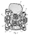
4つのリフレクタ10、11、12、13は1つのリフレクタ支持体30に配置されて該リフレクタ支持体30に固定的に(fix)結合されている。「リフレクタ支持体に固定的に」結合されているとは、これらのリフレクタが支持体30に関し定置的に配設されていることを意味し、有利には、これらのリフレクタが支持体30に直接的に結合されていること、例えば、図2に良好に見出すことができるように、ネジ固定されていることを意味する。
The four
リフレクタ支持体30は、有利には、光源20、21、22、23から生成される熱を運び去ることができる冷却体として構成されている。
The
光源20、21、22、23の各々は、独自の、通常は明白により小さい光源支持体40、41、42、43に配されており、これら4つの光源支持体40、41、42、43はまた、有利には(4つの)冷却体として構成されている。
Each of the
図3は、前方から見た、ばらばらの状態にある4つの光源支持体40、41、42、43を示し、図4は、リフレクタ支持体30に取り付けられた4つの光源支持体40、41、42、43を示す。本発明に応じ、光源支持体40、41、42、43は、リフレクタ支持体30に摺動可能に支持され、リフレクタ支持体30に対し定義された(定められた)位置において固定可能に構成されている。
FIG. 3 shows four light source supports 40, 41, 42, 43 in a disjointed state as viewed from the front, and FIG. 4 shows four light source supports 40, 41, attached to the
この場合、ここに記載の例に対してのみならず、本発明の枠内において一般的に、文字どおりに、光源支持体がリフレクタ支持体に摺動可能に支持されていること、光源支持体がリフレクタ支持体に対し摺動可能であること、有利には光源支持体はリフレクタ支持体に直接的に摺動可能に支持されていることを意味する。 In this case, the light source support is slidably supported by the reflector support in general, not only for the example described here but also within the framework of the present invention. It means that it is slidable relative to the reflector support, preferably the light source support is slidably supported directly on the reflector support.
図4には、(車両への照明ユニット1の組込み(方向)に対する)垂直方向が矢印で示されているが、図示の例においては、光源支持体40、41、42、43はこの方向に摺動可能に構成されている。 In FIG. 4, the vertical direction (with respect to the assembly (direction) of the lighting unit 1 in the vehicle) is indicated by an arrow. In the illustrated example, the light source supports 40, 41, 42, 43 are in this direction. It is configured to be slidable.
以下において、図3及び図4を再度参照すると共に、図5〜図8を参照する。 In the following, reference will be made again to FIGS. 3 and 4 and to FIGS.
光源支持体40、41、42、43をリフレクタ支持体30において垂直方向に簡単に摺動可能にするために、リフレクタ支持体30は、案内溝31a、31b、31c、31dを、有利には各光源支持体40、41、42、43に対し夫々ただ1つの(丁度ないし正確に1つの)案内溝を有するよう構成されている。この例では、案内溝31a、31b、31c、31dは2つに分割されているため、光源支持体当たり2つの溝ということも可能である。案内溝31a、31b、31c、31dは、この場合、夫々結合開口50によって分断(分割)されている(2つに分かれており)。各光源支持体は対応する結合開口50を介してリフレクタ支持体に結合されることができる。結合開口は、例えば、予め開けられた穴であるか、或いは、リフレクタ支持体が成型加工される場合は、成型プロセスの際にリフレクタ支持体にこの穴が設けられる。
In order to enable the light source supports 40, 41, 42, 43 to be easily slidable in the vertical direction on the
各光源支持体40、41、42、43は、そのリフレクタ支持体30を指向する側ないしリフレクタ支持体30に当接する側に、案内溝31a、31b、31c、31dに対応する案内突出部40’、41’、42’、43’を有する。光源支持体はこの案内突出部40’、41’、42’、43’によって関連(対応)する溝内で案内される。
Each
案内突出部40’、41’、42’、43’もまた、リフレクタ支持体30に各光源支持体40、41、42、43を結合するための結合開口51によって分断(分割)されている(2つに分かれている)が、そのため、この場合も、光源支持体当たり2つの突出部(又は分断(分割)突出部)ということができる。光源支持体40、41、42、43の結合開口51は、有利には、光源支持体の摺動方向に延在する長穴であり、光源支持体は該長穴を介してリフレクタ支持体30に所望の調節位置においてネジ52で固定されることができる。
The guide protrusions 40 ′, 41 ′, 42 ′, 43 ′ are also divided (divided) by the
ネジ52は、有利には、上述したように、ねじ込みプロセスの際にリフレクタ支持体に雌ネジを切り込みながらねじ込まれるセルフタッピングネジである。
The
溝内で案内される突出部を使用することにより、位置調整が溝の方向においてのみ可能であると共に、その横方向における位置変化が阻止されることも補償される。自由度のこの削減によって、所望の位置の迅速な調節が可能であると共に、不都合な位置付けの可能性は大きく減少される。 By using the protrusions guided in the groove, position adjustment is possible only in the direction of the groove and it is also compensated that position changes in the lateral direction are prevented. This reduction in degrees of freedom allows a quick adjustment of the desired position and greatly reduces the possibility of inconvenient positioning.
案内溝31a、31b、31c、31dは、長溝として構成されており、案内突出部と同様に垂直(鉛直)方向に直線的に延在する。
The
リフレクタは光源の(位置)調節の前には既にリフレクタ支持体に結合されているため、光源の(位置)調節の際にリフレクタには力の作用は及ばず、かくして、リフレクタの不所望の位置ずれは生じない。 Since the reflector is already coupled to the reflector support prior to the (position) adjustment of the light source, there is no force applied to the reflector during the (position) adjustment of the light source, and thus the undesired position of the reflector. There is no deviation.
リフレクタ支持体は、とりわけ冷却体として構成されるものは、金属部材として、とりわけアルミニウム・ダイカスト部材として構成されることができるため、案内溝は極めて正確に形成することができる。これに応じて、光源の位置も正確に調節することができ、結合の際にも、夫々に割り当てられたリフレクタに対する光源の位置は最早変化しない。 Since the reflector support, especially configured as a cooling body, can be configured as a metal member, in particular as an aluminum die-cast member, the guide groove can be formed very accurately. Correspondingly, the position of the light source can also be adjusted accurately, and the position of the light source relative to the respective assigned reflectors no longer changes during the coupling.
更に、本発明に応じ、ダブルリフレクタ等のマルチリフレクタも使用することができる。通常は、複数のリフレクタは別々に(位置)調節する必要があるが、ダブルないしマルチリフレクタの場合にはこれは不可能である。光源(複数)の本発明に応じた(位置)調節によって、リフレクタ(複数)の(位置)調節は最早不要であり、そのため、ダブルないしマルチリフレクタも使用することができる。 Furthermore, a multi-reflector such as a double reflector can be used according to the present invention. Normally, the reflectors need to be adjusted separately (position), but this is not possible with double or multi-reflectors. By adjusting the (position) of the light source (s) according to the invention, it is no longer necessary to adjust the (position) of the reflector (s), so double or multi-reflectors can also be used.
本発明の場合、とりわけ図1に示されるように、2つの減光(ロービーム)リフレクタ12、13がダブルリフレクタとして構成されている。即ち、2つのリフレクタ12、13は一部材として(一体の部材として)構成されている。
In the case of the present invention, in particular, as shown in FIG. 1, two dimming (low beam)
原理的には、2以上のリフレクタ支持体を夫々1又は複数のリフレクタのために備えることも可能である。例えば、各光源支持体が専用のリフレクタ支持体上で摺動可能に支持されることができるであろうし、4つのリフレクタ支持体が互いに対し固定的に結合されているが、一般的には、既述の通り、ただ1つの(丁度ないし正確に1つの)リフレクタ支持体を備えることが、構造上より簡単である。 In principle, it is also possible to provide two or more reflector supports for one or more reflectors, respectively. For example, each light source support could be slidably supported on a dedicated reflector support, and four reflector supports are fixedly coupled to each other, As already mentioned, it is simpler in construction to have only one (exactly exactly one) reflector support.
有利には、更に、光源支持体が摺動可能に支持される案内溝の表面が(フライス盤で)切削加工され、必要に応じ、その表面が、光源支持体が良好に摺動できるようとりわけ平坦な面が得られるよう、処理されている。 Advantageously, furthermore, the surface of the guide groove on which the light source support is slidably supported is machined (with a milling machine) and, if necessary, the surface is particularly flat so that the light source support can slide well. It has been processed to obtain a good surface.
ハイビームリフレクタ10、11に割り当てられている(即ちその光がこれらのリフレクタに放射される)光源20、21の垂直(鉛直)方向における上下摺動(即ち上方と下方;方向は常にヘッドライトの組立状態(Einbaulage)を基準とする)により、ハイビームのスポットのサイズが変化される。ハイビームリフレクタ10、11に割り当てられている光源20、21の摺動によって、ハイビーム配光のサイズ(ないし量)も適切に適合化することができる。
Up-and-down sliding (ie upward and downward) in the vertical (vertical) direction of the
ロービームリフレクタ12、13の光源22、23の垂直ないし鉛直(上下)方向の摺動により、一次的には、これらのリフレクタによって生成されるロービーム配光の明暗境界がフォーカシングないしデフォーカシングされ、2次的には、該配光が僅かに上下動する。そのため、これらの光源22、23の垂直(鉛直)方向の摺動を介して、ロービーム配光の位置及び明暗境界のシャープネスが相応に調節されることができる。
By sliding the
上述の効果については4つのリフレクタを有する具体的な実施例を用いて説明したが、数値は具体的に記載されたものに限定されない。より多くのリフレクタを使用することも可能であり、例えば、(1つの)ハイビームリフレクタにのみ垂直(鉛直)方向に摺動可能な光源が割り当てられる場合及び/又は(1つの)ロービームリフレクタにのみ垂直(鉛直)方向に摺動可能な光源が割り当てられる場合であっても、上述の効果は生じる。 Although the above-described effect has been described using a specific embodiment having four reflectors, the numerical values are not limited to those specifically described. It is also possible to use more reflectors, for example if only a (one) high beam reflector is assigned a light source slidable in the vertical (vertical) direction and / or only (one) a low beam reflector. Even when a light source slidable in the (vertical) direction is assigned, the above-described effect occurs.
Claims (13)
照明装置(1)はただ1つのリフレクタ支持体(30)を有し、
少なくとも1つの光源(20、21、22、23)は少なくとも1つの光源支持体(40、41、42、43)に配設されており、少なくとも1つの光源支持体(40、41、42、43)はリフレクタ支持体(30)に摺動可能に支持されかつリフレクタ支持体(30)に関し定められた位置に固定可能であり、
2以上のリフレクタ(10、11、12、13)が設けられており、各リフレクタ(10、11、12、13)に対し夫々少なくとも1つの光源(20、21、22、23)を有するただ1つの光源支持体(40、41、42、43)が割り当てられており、該2以上のリフレクタ(10、11、12、13)はリフレクタ支持体(30)に固定的に結合されており、
すべての光源支持体(40、41、42、43)がリフレクタ支持体(30)に摺動可能に支持されかつ固定可能に構成されており、
少なくとも1つのリフレクタ支持体(30)は少なくとも1つの光源支持体(40、41、42、43)のために光源支持体(40、41、42、43)が摺動的に案内される少なくとも1つの案内溝(31a、31b、31c、31d)/少なくとも1つの案内突出部を有し、及び、少なくとも1つの光源支持体(40、41、42、43)は少なくとも1つの対応する案内突出部(40’、41’、42’、43’)/少なくとも1つの対応する案内溝を有し、
少なくとも1つの案内溝(31a、31b、31c、31d)と少なくとも1つの案内突出部(40’、41’、42’、43’)は夫々リフレクタ支持体(30)に光源支持体(40、41、42、43)を結合するための結合開口(50、51)を挟んで向かい合う2つの部分から構成されており、
少なくとも1つの光源支持体(40、41、42、43)の結合開口(51)は長穴として構成されており、
光源(20、21、22、23)はLED光源であり、各LED光源(20、21、22、23)は少なくとも1つの発光ダイオードを含み、
各LED光源(20、21、22、23)ないし少なくとも異なるリフレクタ(10、11、12、13)のLED光源(20、21、22、23)は別々に制御可能かつオン・オフ切り替え可能及び/又は調光可能に構成されている、
照明装置。 An automotive headlight illumination device (1), wherein the illumination device (1) has at least one reflector (10, 11, 12, 13), and the at least one reflector (10, 11, 12, 13) At least one light source (20, 21, 22, 23) is assigned and the reflector from which the light from at least one light source (20, 21, 22, 23) forms a light distribution or part of the light distribution (10, 11, 12, 13) is emitted to the area in front of the lighting device,
The lighting device (1) has only one reflector support (30),
At least one light source (20, 21, 22, 23) is disposed on at least one light source support (40, 41, 42, 43), and at least one light source support (40, 41, 42, 43). ) Is slidably supported on the reflector support (30) and can be fixed in a defined position with respect to the reflector support (30);
Two or more reflectors (10, 11, 12, 13) are provided, each having at least one light source (20, 21, 22, 23) for each reflector (10, 11, 12, 13). Two light source supports (40, 41, 42, 43) are assigned, the two or more reflectors (10, 11, 12, 13) being fixedly coupled to the reflector support (30);
All light source supports (40, 41, 42, 43) are slidably supported and fixed to the reflector support (30),
At least one reflector support (30) is slidably guided by at least one light source support (40, 41, 42, 43) for at least one light source support (40, 41, 42, 43). One guide groove (31a, 31b, 31c, 31d) / at least one guide protrusion and at least one light source support (40, 41, 42, 43) has at least one corresponding guide protrusion ( 40 ′, 41 ′, 42 ′, 43 ′) / having at least one corresponding guide groove,
At least one guide groove (31a, 31b, 31c, 31d) and at least one guide protrusion (40 ', 41', 42 ', 43') is a light source support respectively the reflector support (30) (40, 41 , 42, 43) and two parts facing each other with a coupling opening (50, 51) for coupling,
At least one coupling aperture of the light source support (40, 41, 42, 43) (51) is configured as a long hole,
The light sources (20, 21, 22, 23) are LED light sources, each LED light source (20, 21, 22, 23) includes at least one light emitting diode,
The LED light sources (20, 21, 22, 23) of each LED light source (20, 21, 22, 23) or at least different reflectors (10, 11, 12, 13) can be separately controlled and switched on and off and / or Or configured to be dimmable,
Lighting device.
請求項1に記載の照明装置。 At least one reflector support (30) is configured as a main cooling body;
The lighting device according to claim 1.
請求項1又は2に記載の照明装置。 At least one light source support (40, 41, 42, 43) is configured as a light source cooling body (40, 41, 42, 43),
The lighting device according to claim 1 or 2.
請求項1〜3の何れかに記載の照明装置。 The at least one light source support (40, 41, 42, 43) is configured to be slidable in the vertical direction with respect to the at least one reflector support (30) when the lighting device is assembled.
The illuminating device in any one of Claims 1-3.
請求項1〜4の何れかに記載の照明装置。 Advantageously, at least one guide groove (31a, 31b, 31c, 31d) is formed in the reflector support (30) and at least one corresponding guide projection (40 ′, 41 ′, 42 ′). , 43 ′) are formed on at least one light source support,
The illuminating device in any one of Claims 1-4.
請求項5に記載の照明装置。 At least one guide groove (31a, 31b, 31c, 31d) is configured to be long and linearly extend,
The lighting device according to claim 5.
請求項6に記載の照明装置。 At least one guide groove (31a, 31b, 31c, 31d) is arranged to extend in the vertical direction in the assembled state of the lighting device.
The lighting device according to claim 6.
請求項1〜7の何れかに記載の照明装置。 At least one guide protrusion (40 ′, 41 ′, 42 ′, 43 ′) is configured to extend in the direction of a long and linearly corresponding guide groove (31a, 31b, 31c, 31d),
The illuminating device in any one of Claims 1-7.
請求項1〜8の何れかに記載の照明装置。 There is only one guide groove (31a, 31b, 31c, 31d) and one guide protrusion (40 ′, 41 ′, 42 ′, 43 ′) for each light source support (40, 41, 42, 43). Provided,
The illuminating device in any one of Claims 1-8.
請求項1〜9の何れかに記載の照明装置。 Only four reflectors (10, 11, 12, 13) and only four assigned light source supports (40, 41, 42, 43) are included,
The illuminating device in any one of Claims 1-9.
請求項1〜10の何れかに記載の照明装置。 At least one of the plurality of reflectors is a high beam reflector (10, 11) for generating a high beam distribution or a part of the high beam distribution,
Lighting device according to any one of claims 1-10.
請求項1〜11の何れかに記載の照明装置。 At least one of the plurality of reflectors is a low beam reflector (12, 13) for generating a low beam distribution or a part of the low beam distribution.
Lighting device according to any one of claims 1 to 11.
Applications Claiming Priority (3)
| Application Number | Priority Date | Filing Date | Title |
|---|---|---|---|
| ATA50158/2013 | 2013-03-07 | ||
| ATA50158/2013A AT514022B1 (en) | 2013-03-07 | 2013-03-07 | Lighting device for a vehicle headlight and vehicle headlights |
| PCT/AT2014/050050 WO2014134649A1 (en) | 2013-03-07 | 2014-03-04 | Lighting device for a vehicle headlight |
Publications (2)
| Publication Number | Publication Date |
|---|---|
| JP2016508662A JP2016508662A (en) | 2016-03-22 |
| JP6122513B2 true JP6122513B2 (en) | 2017-04-26 |
Family
ID=50433885
Family Applications (1)
| Application Number | Title | Priority Date | Filing Date |
|---|---|---|---|
| JP2015559394A Active JP6122513B2 (en) | 2013-03-07 | 2014-03-04 | Automotive headlight lighting system |
Country Status (6)
| Country | Link |
|---|---|
| US (1) | US9671080B2 (en) |
| EP (1) | EP2964486B1 (en) |
| JP (1) | JP6122513B2 (en) |
| CN (1) | CN105008180B (en) |
| AT (1) | AT514022B1 (en) |
| WO (1) | WO2014134649A1 (en) |
Families Citing this family (7)
| Publication number | Priority date | Publication date | Assignee | Title |
|---|---|---|---|---|
| AT518118B1 (en) * | 2016-01-11 | 2017-11-15 | Zkw Group Gmbh | Lighting unit for a motor vehicle |
| DE102017115001A1 (en) * | 2017-07-05 | 2019-01-10 | Automotive Lighting Reutlingen Gmbh | Adjustable headlight system |
| US10640475B2 (en) | 2017-09-22 | 2020-05-05 | Hexion Inc. | Compositions and methods to produce alkoxylated triazine-arlhydroxy-aldehyde condensates |
| US10604614B2 (en) | 2017-09-22 | 2020-03-31 | Hexion Inc. | Compositions and methods to produce alkoxylated triazine-arylhydroxy-aldehyde condensates |
| US10435503B2 (en) | 2017-09-22 | 2019-10-08 | Hexion Inc. | Compositions for polyurethane applications |
| WO2019243246A1 (en) | 2018-06-19 | 2019-12-26 | Lumileds Holding B.V. | Operating a lighting module with led elements |
| CN210123140U (en) * | 2019-05-21 | 2020-03-03 | 华域视觉科技(上海)有限公司 | Headlamp module, lighting device, headlamp and vehicle |
Family Cites Families (20)
| Publication number | Priority date | Publication date | Assignee | Title |
|---|---|---|---|---|
| JP3335994B2 (en) * | 1999-12-21 | 2002-10-21 | 松下電器産業株式会社 | Lighting lamp |
| FR2810934B1 (en) | 2000-07-03 | 2002-09-13 | Valeo Vision | ELLIPTICAL PROJECTOR WITH BEAM MODIFICATION BY MOVEMENT OF OPTICAL ELEMENTS |
| WO2005025932A2 (en) * | 2003-09-08 | 2005-03-24 | Schefenacker Vision Systems Usa Inc. | Apparatus and method for mounting and adjusting led headlamps |
| JP4360191B2 (en) * | 2003-12-05 | 2009-11-11 | 株式会社小糸製作所 | Vehicle headlamp |
| JP2005166590A (en) * | 2003-12-05 | 2005-06-23 | Koito Mfg Co Ltd | Vehicular headlamp |
| JP4397856B2 (en) * | 2005-06-06 | 2010-01-13 | 株式会社小糸製作所 | Vehicle lamp and vehicle lamp system |
| FR2891510B1 (en) * | 2005-09-30 | 2009-05-15 | Valeo Vision Sa | ILLUMINATING AND / OR SIGNALING DEVICE FOR A MOTOR VEHICLE INCORPORATING A MATERIAL HAVING A THERMAL ANISOTROPY |
| JP4497073B2 (en) * | 2005-10-05 | 2010-07-07 | 市光工業株式会社 | Vehicle lighting |
| JP2008123753A (en) * | 2006-11-09 | 2008-05-29 | Koito Mfg Co Ltd | Lamp unit for vehicle |
| JP4704327B2 (en) * | 2006-12-19 | 2011-06-15 | 株式会社小糸製作所 | Lighting fixtures for vehicles |
| JP4745272B2 (en) * | 2007-03-14 | 2011-08-10 | 株式会社小糸製作所 | Vehicle lighting |
| DE102007040728B4 (en) * | 2007-08-29 | 2019-01-10 | Automotive Lighting Reutlingen Gmbh | vehicle headlights |
| DE102009030564A1 (en) | 2009-06-26 | 2010-12-30 | Automotive Lighting Reutlingen Gmbh | Lighting device e.g. headlight, for motor vehicle, has housing and light source, that are provided on carrier, where position of carrier along with light source is changed with respect to housing |
| FR2955171A1 (en) | 2010-01-14 | 2011-07-15 | Peugeot Citroen Automobiles Sa | Multifunction headlight for rear or front face of e.g. car to ensure fog light function, has masking element fixed at interior of parabolic reflector in order to delimit two cavities, and distinct light source paced in each cavity |
| US8985825B2 (en) * | 2010-08-30 | 2015-03-24 | Heinz Dücker | Headlight for a vehicle |
| AT510454B1 (en) * | 2010-10-14 | 2013-04-15 | Zizala Lichtsysteme Gmbh | LED LIGHT VEHICLE |
| DE102010048596A1 (en) | 2010-10-15 | 2012-04-19 | Hella Kgaa Hueck & Co. | Headlamp for a vehicle with a main LED light module |
| DE102010054922A1 (en) * | 2010-12-17 | 2012-06-21 | Volkswagen Ag | Headlight for vehicle, comprises semiconductor light source, which is fastened at light source carrier, and optical element, which is arranged in light emission direction of semiconductor light source |
| JP2013004167A (en) * | 2011-06-10 | 2013-01-07 | Koito Mfg Co Ltd | Vehicular headlight |
| JP5939418B2 (en) * | 2012-01-24 | 2016-06-22 | スタンレー電気株式会社 | Vehicle lamp unit |
-
2013
- 2013-03-07 AT ATA50158/2013A patent/AT514022B1/en not_active IP Right Cessation
-
2014
- 2014-03-04 EP EP14714915.7A patent/EP2964486B1/en active Active
- 2014-03-04 CN CN201480012600.8A patent/CN105008180B/en active Active
- 2014-03-04 US US14/772,820 patent/US9671080B2/en active Active
- 2014-03-04 JP JP2015559394A patent/JP6122513B2/en active Active
- 2014-03-04 WO PCT/AT2014/050050 patent/WO2014134649A1/en active Application Filing
Also Published As
| Publication number | Publication date |
|---|---|
| CN105008180B (en) | 2017-04-05 |
| US20160010823A1 (en) | 2016-01-14 |
| AT514022A1 (en) | 2014-09-15 |
| EP2964486A1 (en) | 2016-01-13 |
| WO2014134649A1 (en) | 2014-09-12 |
| US9671080B2 (en) | 2017-06-06 |
| JP2016508662A (en) | 2016-03-22 |
| AT514022B1 (en) | 2015-11-15 |
| EP2964486B1 (en) | 2021-06-30 |
| CN105008180A (en) | 2015-10-28 |
Similar Documents
| Publication | Publication Date | Title |
|---|---|---|
| JP6122513B2 (en) | Automotive headlight lighting system | |
| JP4360191B2 (en) | Vehicle headlamp | |
| US7244057B2 (en) | Headlight | |
| JP6072415B2 (en) | Vehicle lighting | |
| US20130027961A1 (en) | Vehicular lamp | |
| US20100067248A1 (en) | Illumination Unit for Vehicle Headlights, and Vehicle Headlight | |
| US11370351B2 (en) | Aiming adjustment method for vehicle headlamp, aiming adjustment mechanism for vehicle headlamp and vehicle headlamp | |
| EP2719941B1 (en) | Vehicular headlamp comprising a projection lens | |
| JP2005166587A (en) | Vehicular headlamp | |
| KR20140000632A (en) | Optical system unit and vehicular lamp | |
| JP2012238417A (en) | Headlight for vehicle | |
| JP2015046235A (en) | Vehicle lighting fixture | |
| CN108368981B (en) | LED headlamp projection lighting device | |
| JP2011009005A (en) | Vehicular lighting fixture | |
| JP2014165150A (en) | Vehicular lighting fixture | |
| US20160312971A1 (en) | Vehicle lighting fixture | |
| US9482400B2 (en) | Light-emitting device for a motor vehicle headlamp and headlamp equipped with said device | |
| JP4181979B2 (en) | Vehicle headlamp | |
| KR101614849B1 (en) | Structure of high and low beams head light | |
| JP2008262936A (en) | Vehicular head light | |
| JP2019117724A (en) | Vehicular lighting fixture | |
| KR20150068118A (en) | Head lamp for vehicles | |
| JP7425121B2 (en) | Lighting device for floodlights | |
| JP2023536890A (en) | automotive floodlight | |
| KR20170062872A (en) | Lamp for vehicle |
Legal Events
| Date | Code | Title | Description |
|---|---|---|---|
| A977 | Report on retrieval |
Free format text: JAPANESE INTERMEDIATE CODE: A971007 Effective date: 20160624 |
|
| A131 | Notification of reasons for refusal |
Free format text: JAPANESE INTERMEDIATE CODE: A131 Effective date: 20160705 |
|
| A601 | Written request for extension of time |
Free format text: JAPANESE INTERMEDIATE CODE: A601 Effective date: 20161005 |
|
| A521 | Request for written amendment filed |
Free format text: JAPANESE INTERMEDIATE CODE: A523 Effective date: 20161019 |
|
| TRDD | Decision of grant or rejection written | ||
| A01 | Written decision to grant a patent or to grant a registration (utility model) |
Free format text: JAPANESE INTERMEDIATE CODE: A01 Effective date: 20170314 |
|
| A61 | First payment of annual fees (during grant procedure) |
Free format text: JAPANESE INTERMEDIATE CODE: A61 Effective date: 20170331 |
|
| R150 | Certificate of patent or registration of utility model |
Ref document number: 6122513 Country of ref document: JP Free format text: JAPANESE INTERMEDIATE CODE: R150 |
|
| R250 | Receipt of annual fees |
Free format text: JAPANESE INTERMEDIATE CODE: R250 |
|
| R250 | Receipt of annual fees |
Free format text: JAPANESE INTERMEDIATE CODE: R250 |
|
| R250 | Receipt of annual fees |
Free format text: JAPANESE INTERMEDIATE CODE: R250 |
|
| R250 | Receipt of annual fees |
Free format text: JAPANESE INTERMEDIATE CODE: R250 |
|
| R250 | Receipt of annual fees |
Free format text: JAPANESE INTERMEDIATE CODE: R250 |