JP6120866B2 - Equipment for processing containers - Google Patents
Equipment for processing containers Download PDFInfo
- Publication number
- JP6120866B2 JP6120866B2 JP2014542721A JP2014542721A JP6120866B2 JP 6120866 B2 JP6120866 B2 JP 6120866B2 JP 2014542721 A JP2014542721 A JP 2014542721A JP 2014542721 A JP2014542721 A JP 2014542721A JP 6120866 B2 JP6120866 B2 JP 6120866B2
- Authority
- JP
- Japan
- Prior art keywords
- rotor
- suction
- hood
- processing
- container
- Prior art date
- Legal status (The legal status is an assumption and is not a legal conclusion. Google has not performed a legal analysis and makes no representation as to the accuracy of the status listed.)
- Active
Links
Images


Classifications
-
- B—PERFORMING OPERATIONS; TRANSPORTING
- B41—PRINTING; LINING MACHINES; TYPEWRITERS; STAMPS
- B41J—TYPEWRITERS; SELECTIVE PRINTING MECHANISMS, i.e. MECHANISMS PRINTING OTHERWISE THAN FROM A FORME; CORRECTION OF TYPOGRAPHICAL ERRORS
- B41J3/00—Typewriters or selective printing or marking mechanisms characterised by the purpose for which they are constructed
- B41J3/407—Typewriters or selective printing or marking mechanisms characterised by the purpose for which they are constructed for marking on special material
- B41J3/4073—Printing on three-dimensional objects not being in sheet or web form, e.g. spherical or cubic objects
- B41J3/40733—Printing on cylindrical or rotationally symmetrical objects, e. g. on bottles
-
- B—PERFORMING OPERATIONS; TRANSPORTING
- B08—CLEANING
- B08B—CLEANING IN GENERAL; PREVENTION OF FOULING IN GENERAL
- B08B15/00—Preventing escape of dirt or fumes from the area where they are produced; Collecting or removing dirt or fumes from that area
- B08B15/007—Fume suction nozzles arranged on a closed or semi-closed surface, e.g. on a circular, ring-shaped or rectangular surface adjacent the area where fumes are produced
-
- B—PERFORMING OPERATIONS; TRANSPORTING
- B08—CLEANING
- B08B—CLEANING IN GENERAL; PREVENTION OF FOULING IN GENERAL
- B08B15/00—Preventing escape of dirt or fumes from the area where they are produced; Collecting or removing dirt or fumes from that area
- B08B15/02—Preventing escape of dirt or fumes from the area where they are produced; Collecting or removing dirt or fumes from that area using chambers or hoods covering the area
-
- B—PERFORMING OPERATIONS; TRANSPORTING
- B41—PRINTING; LINING MACHINES; TYPEWRITERS; STAMPS
- B41F—PRINTING MACHINES OR PRESSES
- B41F35/00—Cleaning arrangements or devices
-
- B—PERFORMING OPERATIONS; TRANSPORTING
- B41—PRINTING; LINING MACHINES; TYPEWRITERS; STAMPS
- B41J—TYPEWRITERS; SELECTIVE PRINTING MECHANISMS, i.e. MECHANISMS PRINTING OTHERWISE THAN FROM A FORME; CORRECTION OF TYPOGRAPHICAL ERRORS
- B41J3/00—Typewriters or selective printing or marking mechanisms characterised by the purpose for which they are constructed
- B41J3/407—Typewriters or selective printing or marking mechanisms characterised by the purpose for which they are constructed for marking on special material
- B41J3/4073—Printing on three-dimensional objects not being in sheet or web form, e.g. spherical or cubic objects
Landscapes
- Engineering & Computer Science (AREA)
- Manufacturing & Machinery (AREA)
- Cleaning In General (AREA)
- Centrifugal Separators (AREA)
- Extraction Or Liquid Replacement (AREA)
- Coating Apparatus (AREA)
- Auxiliary Devices For And Details Of Packaging Control (AREA)
Description
本発明は、請求項1の上位概念による、容器の処理、特に容器に印刷をするための装置に関する。
The invention relates to the processing of containers according to the superordinate concept of
容器に印刷をすることにより容器の処理をするための装置は、公知である(独国特許出願公開第10 2006 001 223号明細書:特許文献1)。この場合、特にまた、容器が、搬送に従い相並んで接続する、それぞれ垂直な機械軸を中心として回転駆動されるロータを構成する複数の処理区間上を移動され、各ロータの処理区間で、複数の処理ステップを備える処理の1つの処理ステップが行なわれる、例えばカラープリント時の色のセットの塗布、又は、印刷のための容器の前処理、又は、例えばエネルギー投入による、即ち熱及び/又は紫外線及び/又はマイクロ波線及び/又はベータ線による、印刷インクの硬化及び/又は架橋が行なわれる装置が公知である。更に、容器の印刷のため液状又は十分液状の印刷インクが使用されるが、これら印刷インクは、その場合、いわゆるインクジェット方法により動作する、電気もしくは電子制御可能なプリントヘッドもしくはそのノズルによって噴射される。 An apparatus for processing a container by printing on the container is known (German Patent Application Publication No. 10 2006 001 223: Patent Document 1). In this case, in particular, the container is also moved on a plurality of processing sections constituting a rotor which is connected to each other according to the conveyance and is driven to rotate around a vertical mechanical axis. One processing step is performed, for example application of a set of colors during color printing, or pretreatment of a container for printing, or for example by energy input, ie heat and / or UV Devices are known in which printing inks are cured and / or crosslinked by means of microwave rays and / or beta rays. Furthermore, liquid or sufficiently liquid printing inks are used for the printing of the containers, which printing inks are then ejected by an electrically or electronically controllable print head or its nozzle, which operates by the so-called ink jet method. .
処理中に容器を容器キャリヤもしくはいわゆるパックに保持することも公知であるが(独国特許出願公開第10 2009 043 497号明細書:特許文献2)、これら容器キャリヤもしくはパックのそれぞれは、これに保持された容器と共に、処理区間全体を経て移動される。 It is also known to hold containers in container carriers or so-called packs during processing (German Patent Application Publication No. 10 2009 043 497: Patent Document 2), each of these container carriers or packs being Along with the held container, it is moved through the entire processing section.
独国特許出願公開第10 2009 013 477号明細書:特許文献3から、個々の各容器が開放ユニットを備える吸引スリーブ内に収容される吸引装置が公知である。
German Patent Application Publication No. 10 2009 013 477:
容器の処理時、特に印刷時、異物又は有害物質もしくは汚染物質が、例えば印刷時に飛散させられた又は解放させられた印刷インク、その微小インクパーティクル又は微小インク顔料及び溶剤、並びに、エネルギー投入による印刷インクの乾燥時に蒸発した溶剤、又は、UV光による印刷インクの乾燥時に生じるオゾン又は飛散させられた溶剤が、環境に到達してしまうことを回避することができず、これが、特にまた、例えば1時間で36000枚までの多色の印刷画像を実現する高効率で動作する処理装置又は印刷装置の場合、異物又は汚染物質のための吸引装置が設けられていないかぎり、特に環境に対する健康にも有害な著しい負荷や、機械又は装置要素のコントロールされない汚染等を生じさせる。 When processing containers, especially during printing, foreign or harmful or contaminated printing ink, for example, scattered or released during printing, its fine ink particles or fine ink pigments and solvents, and printing with energy input It cannot be avoided that the solvent evaporated during drying of the ink, or the ozone generated when the printing ink is dried by UV light or the scattered solvent reach the environment. In the case of a processing device or printing device that operates with high efficiency to achieve up to 36000 multicolored printed images in time, it is particularly harmful to the health of the environment unless a suction device for foreign matter or contaminants is provided. Cause significant load and uncontrolled contamination of machine or equipment elements.
本発明の課題は、高い作動安全性及び低減した構造的及びエネルゲティック的な費用で処理時に発生する異物又は汚染物質の効果的な吸引を可能にする吸引装置を有する容器の処理、特に容器に印刷をするための装置を示すことにある。 The object of the present invention is the treatment of a container with a suction device that enables effective suction of foreign matter or contaminants generated during processing with high operational safety and reduced structural and energetic costs, in particular containers An apparatus for printing is shown.
この課題を解決するため、請求項1に応じた装置が形成されている。
In order to solve this problem, a device according to
本発明による装置の場合、異物又は汚染物質の吸引は、処理位置において直接的に、即ち異物又は汚染物質の発生個所において直接的に、しかもロータと共に回転しない、ロータに向かって開放した吸引フードを介して行なわれ、この吸引フードは、回転方向に少なくとも、ロータもしくはロータ周囲の回転運動の処理区間に相当する角度領域にわたって延在する。ロータの回転によって、また処理中の容器の生じ得る回転又は回転運動によって生じる空気の乱流は、基本的に、異物又は汚染物質の吸引に対する影響又は実質的にマイナスの影響を有することがなく、むしろ、ロータの回転運動は、遠心力による処理位置からの異物及び汚染物質の加速させた除去のため並びに排気流の加速のために利用され、これにより異物又は汚染物質の吸引が少なくとも支援される。 In the case of the device according to the invention, the suction of foreign matter or contaminants is performed directly at the processing position, i.e. directly at the point of occurrence of foreign matter or contaminants, and does not rotate with the rotor and is open to the rotor. This suction hood extends in the rotational direction over at least an angular region corresponding to the rotor or a processing section for rotational movement around the rotor. The turbulence of the air caused by the rotation of the rotor and by the possible rotation or rotational movement of the container being processed basically has no influence on the suction of foreign objects or contaminants or a substantially negative influence, Rather, the rotational movement of the rotor is used for accelerated removal of foreign matter and contaminants from the processing position by centrifugal force and for acceleration of the exhaust flow, thereby at least assisting the suction of foreign matter or contaminants. .
それぞれの吸引フードは、そのフード内室を、そこの流れ特性に関して空気力学的に最適に、しかもエネルギー効率及びプロセス効率の意味で、特に、処理又は印刷プロセスにプラスに作用する空気流が、注入した吸引エネルギーが最小である場合に処理位置において得られ、吸引ユニットが、それに応じてコストに関して効率的に作動させ得るように、形成されている。 Each suction hood is injected with an air flow that optimizes its hood interior aerodynamically with respect to its flow characteristics and, in terms of energy efficiency and process efficiency, in particular positively affecting the processing or printing process. It is obtained in the processing position when the suction energy is minimal, and the suction unit is configured so that it can be operated efficiently in terms of cost accordingly.
“容器”は、本発明の意味で、特に、それぞれ金属、ガラス及び/又は合成樹脂から成る缶、瓶、チューブ、袋であり、しかしながらまた製品を注入するために適した他のパック手段である。 “Containers” in the sense of the present invention are in particular cans, bottles, tubes, bags, each made of metal, glass and / or synthetic resin, but also other pack means suitable for injecting products. .
“実質的”もしくは“ほぼ”との表現は、本発明の意味では、それぞれ正確な値からの±10%、好ましくは±5%の偏差及び/又は機能のために些細な変化の形態の偏差を意味する。 The expression “substantially” or “approximately” means in the sense of the present invention a deviation of +/− 10%, preferably +/− 5% from the exact value and / or a deviation in the form of a minor change due to the function, respectively. Means.
本発明の発展形、利点及び適用の可能性は、後続の実施例の説明とそれぞれの図からわかる。この場合、説明される及び/又は絵で表現される全ての特徴は、単独でも任意に組み合わせても基本的に本発明の対象であり、それぞれの請求項及びその引用請求項における要約に依存しない。また、それぞれの請求項の内容は、明細書の構成要素を成す。 The developments, advantages and applicability of the present invention can be seen from the description of the following examples and the respective figures. In this case, all features described and / or pictorially represented, whether alone or in any combination, are basically the subject of the present invention and do not depend on the summary of each claim or its cited claims. . The content of each claim constitutes a component of the specification.
本発明を、以下で実施例の図に基づいて詳細に説明する。 The invention will be described in detail below with reference to the figures of the examples.
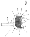
それぞれの図において、1は、その他は図示してない処理機械もしくは容器2に印刷をするための、例えばマルチカラープリントにより容器2の容器外面又は外周面に直接的に印刷するための装置の1つのモジュールの垂直な機械軸MAを中心として回転駆動可能なロータである。装置は、例えば複数のロータ又はモジュールを備え、これらロータ又はモジュールは、容器搬送方向の搬送に従い相並んで接続し、その処理位置3において、それぞれ1つの部分処理、例えばマルチカラープリントの色のセットの塗布、印刷のための容器表面の準備、印刷インクの乾燥等が実施される。
In each figure, 1 is an
ロータ1の周囲には、処理位置3が、機械軸MAを中心として均等な角度間隔で分配され、この機械軸MAから同じ半径方向の間隔で構成され、これら処理位置において、容器2は、図示した実施形態の場合は、それぞれ吊り下げられて、即ちその容器軸を機械軸MAに対して平行な垂直方向に整向して、しかも容器キャリヤ4に保持されている。容器キャリヤは、図示した実施形態の場合は、いわゆる“パック”であり、これらパックは、容器2と共に装置を経て移動され、処理中に容器2のその容器軸を中心とした制御された回転又は旋回運動を可能にする。
Around the
ロータ1の処理位置3に、それぞれ1つの処理ヘッド5が設けられ、この処理ヘッドによって、それぞれの処理ステップ、例えばマルチカラープリントの色のセットの塗布が実施される。この場合は、処理ヘッド5は、プリントヘッドで、この場合特にインクジェット方法により動作する電気制御可能なプリントヘッドであり、これらプリントヘッドによって、液状の、即ち液状のマトリックス(溶剤)内に顔料を含む印刷インクが、ノズルを介して、処理位置3に配置されたそれぞれの容器に塗布される。
One
ロータ1における処理位置3が、例えば、エネルギー投入、例えば熱、UV光等によって印刷インクを完成させるためのものである場合、これら処理位置3における処理ヘッド5は、相応のエネルギー線を放出する処理ヘッド、例えば赤外線放射器及び/又は紫外線放射器等である。
If the
印刷時に飛散される容器2に到達しない印刷インク及び/又は印刷インク又は印刷物の乾燥時に解放される溶剤残余及び/又はUV線によって発生したオゾンが、異物又は汚染物質としてコントロールされずに環境に到達することを回避するため、ロータ1と共に回転しない吸引ユニット6が設けられ、この吸引ユニットは、吸引フード7によって、ロータ1を、ロータ回転方向Aにその周囲の一部にわたって、即ちロータ1の回転運動のある角度領域又は実質的にある角度領域にわたって包囲し、この角度領域、例えば約180°〜270°の角度領域にわたって、処理位置3における容器2の処理が行なわれる。
Printing ink that does not reach
吸引フード7もしくはそのハウジングは、機械軸MAも方向に、少なくとも処理位置3の相応の高さと等しい高さを備える。図示した実施形態の場合、吸引フード7もしくはそのハウジングが備える高さは、ロータ1の高さよりも大きいので、吸引フード7は、ロータ1の下側からその上側を超えるまでに延在する。
The suction hood 7 or its housing has a height at least equal to the corresponding height of the
より詳細には、吸引フード7のハウジングは、図示した実施形態ではその表面側がそれぞれ機械軸MAに対して垂直又は実質的に垂直な平面内に配置された下のハウジング壁8及び上のハウジング壁9と、間隔を置いて機械軸MAとロータを部分的に包囲する外側の周囲壁10とから成り、この周囲壁は、ロータ回転方向に対する吸引フード7の前方の終端7.1と吸引フードの後方の終端7.2においてそれぞれ、ロータ1に向かう方向に延在する周壁部分10.1もしくは10.2に移行する。従って、ロータ1をその周囲の一部にわたって包囲する、ロータ1と共に回転しない吸引フード10は、特に半径方向にロータ1に向かって開放したフード内室11を構成する。
More specifically, the housing of the suction hood 7 has a
両終端7.1と7.2の間の中心又はほぼ中心で、フード内室11内の、周囲壁10によって構成される後壁に、少なくとも1つのエアフィルタの形態の大面積のフィルタ装置12が設けられている。図示した実施形態では機械軸MAに対して、終端7.1と7.2の間の吸引フード7の長さの半分よりも実質的に大きい角度領域にわたって延在するフィルタ装置12は、下のハウジング壁8の内面から上のハウジング壁9の内面にまで達し、フード内室11を、吸引フード7のロータ1とは反対の後側に設けられたチャンバ13から分離する。チャンバ7もしくはその環境に対して閉じた内室は、吸気通路接続部14.1において吸引通路14と接続され、この吸引通路は、比較的大きい横断面を備え、例えば少なくとも1つのチューブ及び/又は少なくとも1つのホースシステムによって構成され、図示してない負圧源又は吸込み源、例えば吸込みブロアの吸込み又は負圧入力部と接続されている。
Large
機械軸MAを中心として駆動されるロータ1における容器2の処理中、処理時に発生する異物又は汚染物質もしくはこれらを含む排気は、ロータ1の周囲もしくはそこの処理位置3から、即ち発生個所において直接的に吸引され、排気内の異物又は汚染物質は、少なくとも部分的に既にフィルタユニット12において濾過される。できるだけ最適な吸引作用を得るため、ロータ1は、図示した実施形他の場合、その処理位置3を備える周囲領域がフード内室11内に達する。更に、フード内室11内には、誘導板として作用する層板状の壁要素15が設けられ、しかも両終端7.1及び7.2とこれら終端の間の領域内に設けられている。
During processing of the
図示した実施形態の場合、ロータ1の周囲からも、吸込み通路11.1を形成するために周囲壁10の内側からも間隔を置いたこれら壁要素15は、それぞれ下のハウジング壁8から上のハウジング壁9にまで延在し、ロータ回転方向Aで吸気通路接続部14.1の前もしくは吸引フード7の第1の部分長さ(例えば半分)の上に設けられた壁要素15においては、ロータ1の周囲とそれぞれの壁要素15の間の間隔が、ロータ回転方向Aに増加し、ロータ回転方向Aで吸気通路接続部14.1の後もしくは吸引フード17の第2の部分長さ(例えば半分)の上に設けられた壁要素15においては、ロータ1の周囲とそれぞれの壁要素15の間の間隔がロータ回転方向Aに減少するように、整向されてもしくは傾斜させられている。
In the case of the illustrated embodiment, these
壁要素15は、吸引能力の最適な分配をするため及び乱流を回避しつつ最適な流動特性の達成をするために寄与する。その他、吸引ユニット6のため、特に、容器2の処理時に発生する異物又は汚染物質が既にロータ1の回転から生じる遠心力によって半径方向にロータ1に向かって開放したフード内室11内に移送されることによって既に、吸引通路14に接続された吸引ブロワの能力を低下させた時の特に効果的な吸引作用が得られる。
The
図4及び5は、別の実施形態として吸引ユニット6aを示すが、この吸引ユニットは、吸引ユニット6の代わりに使用することができ、更にまた吸引フード7に相当する吸引フード16を備え、この吸引フードのフード内室17は、フィルタユニットを介して吸引通路14と接続され、この吸引通路を介して図示してない吸引ブロワと接続されている。吸引フード16は、更にまたロータ1の周囲の一部にわたって、即ち機械軸MAに対して360°より小さい角度領域、例えば訳180°〜270°の角度領域にわたって、ロータ回転方向Aに延在する。フード内室17は、下側を部分リング状の底壁18によって、上側をチャンバ19によって、そして周囲を周囲壁20によって画成され、この周囲壁は、この実施形態の場合は、部分円形シリンダ状に機械軸MAを間隔を置いて包囲する。ロータ1は、図4及び5には図示されていない。しかしながら、これらの図には、機械軸MAが図示され、この機械軸は、更にまた同時にロータ1の軸でもある。
4 and 5 show a
フード内室17内には、誘導板として作用する層板状の複数の壁要素21が設けられ、これら壁要素は、それぞれ下のハウジング壁18から出発してチャンバ19内まで延在し、このチャンバは、そのハウジング下側18の側が開放しているが、それ以外は環境に対して閉じられている。チャンバ19は、終端7.1に相当する終端16.1と終端7.2に相当する終端16.2の間の吸引フード16の角度長さ全体にわたって延在する。
A plurality of layered plate-
壁要素21は、下のハウジング壁18に固定されたその下の終端21.1と、チャンバ19内に達するその上の終端21.2とが、それぞれ、機械軸MAに対して半径方向又は実質的に半径方向に整向されているが、上の終端21.2は、各壁要素21の下の終端21.1に対してロータ回転方向Aに、ある角度値分ずらされており、この角度値は、図示した実施形態の場合は、ほぼ、互いに隣接する壁要素21の間のピッチ間隔に相当するか、このピッチ間隔よりも若干小さい。更に、壁要素21は、そのロータ回転方向Aに対して前方の側が、凹に湾曲させられている。
The
その上の終端21.2の領域内を、壁要素21は、付加的な壁要素22に固定され、この壁要素は、既にチャンバ19の壁の一部である。内部で、壁要素21の間に構成される流路23が接続し、吸込み通路11.1に相当する吸込み通路を構成するチャンバ19の本来の内室は、壁要素22の上に存在する。チャンバ19内には、例えば、フィルタユニット12に相当するフィルタユニットが設けられている。
In the region of the end 21.2 above it, the
容器2の処理中、ロータ1が回転している時に、異物又は汚染物質を有する排気は、それぞれ2つの壁部分21の間に構成された流通路23、チャンバ19及び吸引通路14を介して処理位置3の領域から吸い出される。チャンバ19内に、フィルタユニット12に相当するフィルタユニットが設けられている場合、このフィルタユニットにおいて、排気内に存在する異物又は汚染物質が、少なくとも部分的に分離される。
During processing of the
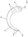
図6〜9は、別の実施形態として、吸引フード7に相当する吸引フード24を有する吸引ユニット6bを示すが、この吸引フードは、ロータ1と共に回転せずに、ロータ回転方向Aにロータ周囲の部分領域にわたって、例えば180°〜270°の角度領域にわたって延在する。ロータ周囲に処理位置3が設けられている。平面図で三日月状の吸引フード24は、フード内室25を構成し、このフード内室は、更にまたロータ軸もしくは機械軸MAに対して半径方向にロータ1の周囲に向かって開放し、下のハウジング壁26、上のハウジング壁27及び図示した実施形態では機械軸MAに対して同軸に延在する部分円シリンダ状の周囲壁28によって画成されている。フード内室25内には、誘導板として作用する複数の壁要素29が設けられ、これら壁要素は、下のハウジング壁26から上のハウジング壁27にまで延在し、ハウジング壁26及び27のロータ1に隣接するエッジにまで達する。しかしながら、周囲壁28から、壁要素29は、吸込み通路25.1を形成するために間隔を置いており、この吸込み通路は、フード内室25内でロータ回転方向Aに、この回転方向に対して前方の終端24.1から吸引フード24の後方の終端24.2にまで延在する。壁要素29は、それぞれ機械軸MAに対して平行な軸を中心として曲げられ、しかも、各壁要素のロータ1に隣接する、ハウジング壁26と27の間に延在する内側のエッジが、ロータ1から離れて位置する相応の外側のエッジに対して、ロータ回転方向Aと反対にある角度値分ずらされ、この角度値は、例えば2つの壁要素29のピッチ間隔に相当する。ロータ回転方向Aに対してその前側をそれぞれ凸に、その後側を凹に湾曲させられた壁要素29は、吸込み通路25.1に接続する流通路30を構成する。
FIGS. 6 to 9 show a suction unit 6b having a
特に図6が示すように、吸引フード24もしくはそのハウジングは、終端24.1の領域内で吸引フード24とロータ1の周囲の間に入口ホッパ31が構成されるように形成され、この入口ホッパは、そこで吸引フード24の全長よりも小さい角度領域もしくは角度長さにわたって、終端24.1から出発して、先ず吸引フード24とロータ1の周囲の間に大きい間隔があり、この間隔が、次にロータ回転方向Aに縮小され、しかも図示した実施形態の場合は連続的で段差なく縮小されるように構成されている。終端24.2の領域内では、図示した実施形態ではその軸が機械軸MAに対して平行に整向され、図示してない吸引通路14を接続した吸引チューブ32が、フード内室25内に達する。そのハウジング壁26に隣接する終端を閉鎖された吸引チューブは、その外周面が、多数の開口によって篩上に形成されて、即ち篩状の構造33を備え、この構造を介して、吸込み通路25.1は、吸込みチューブ32の内部と接続している。
In particular, as FIG. 6 shows, the
図示した実施形態の場合は、吸引フード24が旋回可能で、しかも機械軸MAに対して平行な軸を中心として旋回可能であり、この軸は、例えば吸引チューブ32の軸である。従って、吸引フード24は、クリーニング、整備、修理の目的等のために図6に図示したロータ1に隣接する動作位置から、ロータ1から離れる旋回をさせることができる。
In the case of the illustrated embodiment, the
基本的に、吸込み通路25.1と吸引チューブ32の間の移行部に、即ち例えば篩状の構造33に、フィルタユニット12に相当するフィルタユニットを設ける可能性もある。
Basically, a filter unit corresponding to the
吸引ユニット6bは、本発明の特に好ましい実施形態に相当するが、この実施形態の場合、吸引通路14もしくは吸込みチューブ32のための接続部が、ロータ回転方向Aに対して後の終端24.2に存在する。ロータ1がロータ周囲に処理位置3及びその機能要素だけによって備える、半径方向にロータ軸に向かって突出する後置した領域を有する構造により、ロータ1が回転している時、流通路30及び吸込み通路25.1を経て吸引チューブ32までの吸引フード24内の空気流が発生され、この空気流は、吸込みチューブ32と接続された吸込みブロワのエネルギー消費を強く低減させた時の全ての異物又は汚染物質の迅速かつ完全な除去もしくは“吸引”を支援する。
The suction unit 6b corresponds to a particularly preferred embodiment of the invention, but in this embodiment the connection for the
図5からわかるように、周囲壁20は、壁要素21及び壁要素22と共に1つの構造ユニットを構成するが、この構造ユニットは、容器処理機械の下のハウジング壁18を構成するボードの上又は下のハウジング壁18を構成するテーブルの上面の上に固定され、必要時に、例えばクリーニング及び/又は修理の目的のために下のハウジング壁18から取外し及び/又は交換することができる。
As can be seen from FIG. 5, the
本発明は、前記のように実施例で説明した。多くの変更並びに変容が、これにより本発明の根底にある発明思想から離れることなく可能であることがわかる。全ての構成は、不動の、即ちロータ1と共に回転しない吸引フードが、ロータの横に、ロータをその周囲の一部にわたってロータ回転方向Aに包囲するように設けられていること、容器2の処理時に発生する異物又は汚染物質の処理位置からの除去が、発生個所において直接的に行なわれ、ロータ1の回転運動が、遠心力による処理位置3からの異物及び汚染物質の加速させた除去のため並びに排気流の加速のために利用され、これにより異物又は汚染物質の吸引が少なくとも支援されることが共通している。
The present invention has been described in the embodiments as described above. It will be appreciated that many changes and modifications can be made thereby without departing from the inventive idea underlying the present invention. In all configurations, a stationary hood, i.e. a suction hood that does not rotate with the
前記のように、ロータ1が、複数のロータ1を有する装置又は処理機械の一部であり、これらロータの内、少なくとも、処理中に環境に負荷を与える異物又は汚染物質が解放されるロータが、吸引ユニット6,6a又は6bを備え、その場合、各ロータ1において、複数の処理ステップを備える処理の1つの処理ステップが実施されることから出発した。しかしながら、本発明に応じて、装置又は処理機械は、唯一のロータ1しか備えないことができ、その場合は、このロータにおいて、該当する処理位置3において完全な処理が実施される。
As described above, the
1 ロータ
2 容器
3 処理位置
4 容器キャリヤ又はパック
5 処理ヘッド
6,6a,6b 吸引ユニット
7 吸引フード
7.1,7.2 吸引フードの終端
8,9 ハウジング壁
10 周囲壁
10.1,10.2 内側に向かって案内される周囲壁部分
11 フード内室
12 フィルタユニット
13 チャンバ
14 吸引通路
14.1 吸気通路接続部
15 壁要素又は誘導板
16 吸引フード
17 フード内室
18 ハウジング壁
19 チャンバ
20 周囲壁
21 壁要素又は誘導板
21.1,21.2 誘導板の下又は上の終端
22 壁部分
23 流通路
24 吸引フード
25 フード内室
25.1 吸込み通路
26,27 ハウジング壁
28 周囲壁
29 誘導板又は壁要素
30 流通路
31 入口ホッパ
32 吸引チューブ
33 篩構造
A ロータ回転方向
MA 機械軸
DESCRIPTION OF
Claims (10)
吸引ユニット(6,6a,6b)が、ロータ(1)と共に移動されない少なくとも1つの吸引フード(7,16,24)を備え、この吸引フードが、ロータ回転方向(A)に少なくともロータ周囲の一部にわたってロータ(1)を横から包囲するように延在し、機械軸(MA)に対して半径方向にロータ(1)に向かって開放したフード内室(11,17,25)を構成し、このフード内室が、少なくとも1つの吸引通路(14,32)を介して、例えば吸込みブロワの形態の少なくとも1つの吸込み装置と接続され、フード内室(11,17,25)内に、誘導板として作用する壁要素(15,21,29)が設けられ、これら壁要素が、その間に流通路(23,30)を構成し、これら流通路は、吸引フード(7,16,24)のロータ(1)の側が開放しており、吸引フード(7,16,24)の内部で、全ての流通路(23,30)のため又は流通路のグループのために共通の吸込み通路(11.1,19,25.1)に接続すること、を特徴とする装置。 Having at least one rotor (1), this rotor having a plurality of processing positions (3) around the rotor and rotating in the rotor rotation direction (A) about a vertical rotor axis or machine axis (MA) In the device for processing the container (2), ie printing on the container (2), which is drivable and has at least one suction device for sucking out foreign matter or contaminants generated during processing,
The suction unit (6, 6a, 6b) includes at least one suction hood (7, 16, 24) that is not moved together with the rotor (1), and this suction hood is at least one around the rotor in the rotor rotation direction (A). Hood inner chambers (11, 17, 25) that extend so as to surround the rotor (1) from the side and open to the rotor (1) in the radial direction with respect to the machine shaft (MA). The hood inner chamber is connected to at least one suction device, for example in the form of a suction blower, via at least one suction passage (14, 32) and guided into the hood inner chamber (11, 17, 25). Wall elements (15, 21, 29) acting as plates are provided, these wall elements constituting flow passages (23, 30) between them, which flow passages of the suction hood (7, 16, 24) Rotor 1) side is open and within the suction hood (7, 16, 24), a common suction passage (11.1,1) for all the flow passages (23, 30) or for a group of flow passages 19, 25.1).
Applications Claiming Priority (3)
| Application Number | Priority Date | Filing Date | Title |
|---|---|---|---|
| DE102011119171A DE102011119171B3 (en) | 2011-11-23 | 2011-11-23 | Apparatus for treating containers with a suction device |
| DE102011119171.6 | 2011-11-23 | ||
| PCT/EP2012/003841 WO2013075764A1 (en) | 2011-11-23 | 2012-09-13 | Device for processing containers |
Publications (3)
| Publication Number | Publication Date |
|---|---|
| JP2015506880A JP2015506880A (en) | 2015-03-05 |
| JP2015506880A5 JP2015506880A5 (en) | 2016-12-15 |
| JP6120866B2 true JP6120866B2 (en) | 2017-04-26 |
Family
ID=46968128
Family Applications (1)
| Application Number | Title | Priority Date | Filing Date |
|---|---|---|---|
| JP2014542721A Active JP6120866B2 (en) | 2011-11-23 | 2012-09-13 | Equipment for processing containers |
Country Status (6)
| Country | Link |
|---|---|
| US (1) | US9162440B2 (en) |
| EP (1) | EP2782687B1 (en) |
| JP (1) | JP6120866B2 (en) |
| CN (1) | CN103906582B (en) |
| DE (1) | DE102011119171B3 (en) |
| WO (1) | WO2013075764A1 (en) |
Families Citing this family (10)
| Publication number | Priority date | Publication date | Assignee | Title |
|---|---|---|---|---|
| DE102011113150A1 (en) * | 2011-09-14 | 2013-03-14 | Khs Gmbh | Method and device for treating packaging by applying equipment |
| DE102012214349A1 (en) | 2012-08-13 | 2014-02-13 | Krones Aktiengesellschaft | Printing device, printhead therefor and method for vacuuming ink |
| DE102013205232A1 (en) | 2013-03-25 | 2014-09-25 | Krones Ag | Printing device for printing on containers |
| DE102013217663B4 (en) * | 2013-09-04 | 2023-11-02 | Krones Ag | Direct printing machine with two cooling systems |
| DE102013217659A1 (en) | 2013-09-04 | 2015-03-05 | Krones Ag | Container treatment machine for printing on containers |
| CN105881886A (en) * | 2016-05-11 | 2016-08-24 | 天津市天鹏建筑器材有限公司 | Hot melt connection mechanism with suction nozzles for plastic pipe |
| JP6934604B2 (en) * | 2016-05-30 | 2021-09-15 | パナソニックIpマネジメント株式会社 | Heat conduction sheet and sheet heater using it |
| DE202016103010U1 (en) * | 2016-06-07 | 2017-09-09 | Krones Ag | Apparatus for direct inkjet printing of containers |
| DE102017215434A1 (en) | 2017-09-04 | 2019-03-07 | Krones Ag | Air conditioning of direct printing machines |
| CN115366538B (en) * | 2022-09-13 | 2023-10-24 | 郑州戴纳光电技术有限公司 | UV printing ink jet numbering machine |
Family Cites Families (24)
| Publication number | Priority date | Publication date | Assignee | Title |
|---|---|---|---|---|
| GB986538A (en) * | 1962-09-20 | 1965-03-17 | Pneumatic Scale Corp | Container cleaning machine |
| DE2322219A1 (en) * | 1973-05-03 | 1974-11-14 | Winterwerb Streng Co Gmbh | METHOD AND DEVICE FOR THE REMOVAL OF LABELS AND SCREW CAPS FROM CONTAINERS, SUCH AS BOTTLES OR THE LIKE |
| DE2755131C2 (en) * | 1977-12-10 | 1982-12-16 | Voith Transmit GmbH, 4330 Mülheim | Coupling for rigidly connecting two coaxial machine parts suitable for transmitting torque |
| DE3812678C3 (en) * | 1988-04-16 | 1996-04-11 | Heidelberger Druckmasch Ag | Device for cleaning cylindrical surfaces in rotary printing machines |
| DE58901892D1 (en) * | 1989-01-26 | 1992-08-27 | Rieter Ag Maschf | CLEANING MACHINE FOR TEXTILE FIBERS. |
| US5150502A (en) * | 1989-04-14 | 1992-09-29 | Roberson James H | Textile fiber length sorting apparatus and method |
| EP0562149B1 (en) * | 1992-03-27 | 1995-05-31 | Schablonentechnik Kufstein Aktiengesellschaft | Apparatus for laser machining a hollow cylinder having a thin wall |
| DE9303813U1 (en) * | 1993-03-16 | 1993-08-05 | Technologie-Zentrum Holzwirtschaft Gmbh, 32657 Lemgo, De | |
| DE4439081A1 (en) | 1994-11-02 | 1996-05-09 | Kronseder Maschf Krones | Method of removing sleeve=type labels from bottles etc |
| US5540152A (en) * | 1995-04-10 | 1996-07-30 | Demoore; Howard W. | Delivery conveyor with control window ventilation and extraction system |
| JP4165694B2 (en) * | 2002-09-11 | 2008-10-15 | ゼネラルパッカー株式会社 | Packaging method of beverage extraction material in extraction bag |
| US6960124B2 (en) * | 2003-01-31 | 2005-11-01 | Wy Peron Lee | Cutting machine with environment control arrangement |
| DE10355996A1 (en) * | 2003-11-27 | 2005-06-30 | Stork Prints Austria Gmbh | Process for the production of flexographic printing plates by means of laser engraving as well as suitable apparatus |
| DE102006001223A1 (en) * | 2006-01-10 | 2007-07-12 | Khs Ag | Apparatus for printing on bottles or similar containers |
| DE102006053821A1 (en) * | 2006-11-14 | 2008-05-15 | Francotyp-Postalia Gmbh | Printing device for franking machine, has print head discharging ink drop from nozzle in such manner that essentially unimpaired suction flow is adjustable between nozzle and suction inlet that is directly arranged adjacent to nozzle |
| DE102006058955B4 (en) | 2006-12-12 | 2014-07-24 | DüRR DENTAL AG | Suction device for dental, medical and industrial purposes |
| JP2008213310A (en) * | 2007-03-05 | 2008-09-18 | Canon Inc | Recording apparatus |
| DE102008013174B3 (en) | 2008-03-07 | 2009-12-17 | Robert Thomas Metall- Und Elektrowerke Gmbh & Co. Kg | Rotary fan for use in e.g. chamber dryer, for drying ceramic molded blank, has drive for rotatably driving air distributor, and bypass channels attached to air distributor and connected with nozzles for dry air supply at nozzles |
| DE102008049241A1 (en) | 2008-09-26 | 2010-04-08 | Khs Ag | Device for applying in each case a multiple printing on packaging |
| DE102009013477B4 (en) * | 2009-03-19 | 2012-01-12 | Khs Gmbh | Printing device for printing on bottles or similar containers |
| DE102009033134B3 (en) * | 2009-07-15 | 2010-12-02 | Netstal-Maschinen Ag | Method and device for extracting vapors in an injection molding machine |
| DE102009043497B4 (en) * | 2009-09-30 | 2012-05-31 | Khs Gmbh | Device for treating packaging |
| DE102010013100A1 (en) * | 2009-11-06 | 2011-05-12 | Christian Maass | Feinstaubabsaugeeinrichtung |
| DE102010051539A1 (en) * | 2010-11-18 | 2012-05-24 | Murrplastik Systemtechnik Gmbh | Device for labeling license plates |
-
2011
- 2011-11-23 DE DE102011119171A patent/DE102011119171B3/en not_active Expired - Fee Related
-
2012
- 2012-09-13 US US14/358,344 patent/US9162440B2/en not_active Expired - Fee Related
- 2012-09-13 JP JP2014542721A patent/JP6120866B2/en active Active
- 2012-09-13 WO PCT/EP2012/003841 patent/WO2013075764A1/en active Application Filing
- 2012-09-13 CN CN201280051675.8A patent/CN103906582B/en not_active Expired - Fee Related
- 2012-09-13 EP EP12766883.8A patent/EP2782687B1/en not_active Not-in-force
Also Published As
| Publication number | Publication date |
|---|---|
| US20140290515A1 (en) | 2014-10-02 |
| EP2782687B1 (en) | 2016-03-02 |
| US9162440B2 (en) | 2015-10-20 |
| WO2013075764A1 (en) | 2013-05-30 |
| EP2782687A1 (en) | 2014-10-01 |
| CN103906582A (en) | 2014-07-02 |
| CN103906582B (en) | 2015-11-25 |
| JP2015506880A (en) | 2015-03-05 |
| DE102011119171B3 (en) | 2013-02-21 |
Similar Documents
| Publication | Publication Date | Title |
|---|---|---|
| JP6120866B2 (en) | Equipment for processing containers | |
| JP5571165B2 (en) | Printing device for printing on containers such as bottles | |
| EP2783852B1 (en) | Printing apparatus for printing on containers | |
| JP5361885B2 (en) | Equipment for printing on containers | |
| AU2007280132B2 (en) | Method and apparatus for sealing capsules | |
| EP2845738B1 (en) | Device for printing on containers | |
| CN106133880A (en) | Substrate board treatment and substrate processing method using same | |
| CN102628640B (en) | Vacuum drying machine | |
| WO2017199602A1 (en) | Drying unit, tablet printing device, and drying method | |
| DE102015222999A1 (en) | Direct printing machine and method for printing on containers with direct printing | |
| WO2013183179A1 (en) | Gas feed device in powder/granular material feeder | |
| DE102013214935A1 (en) | Printing station and method for direct printing of containers | |
| JP2005185906A (en) | Apparatus for washing outer periphery of mouth part of container | |
| KR100765755B1 (en) | Drying device and ink-jet image forming apparatus adopting the same | |
| CN115727651B (en) | PC alloy material dryer | |
| CN216033185U (en) | Quick drying's packing lithography apparatus | |
| RU2404065C1 (en) | Device and method of containers sealing | |
| US20190299127A1 (en) | Separation device for separating a solid material from a conveying stream and method for maintaining such a separation device | |
| CN108202127B (en) | A kind of durable centrifugation regenerating device | |
| JP5216725B2 (en) | Substrate processing apparatus and substrate processing method | |
| CN117259301A (en) | Traditional Chinese medicine GAP management standard processing system | |
| JP2006334466A (en) | Filtration drier and filtration drying method using the filtration drier | |
| BRPI0715125B1 (en) | METHOD AND APPARATUS FOR SEALING CAPSULES |
Legal Events
| Date | Code | Title | Description |
|---|---|---|---|
| A521 | Written amendment |
Free format text: JAPANESE INTERMEDIATE CODE: A523 Effective date: 20150911 |
|
| A621 | Written request for application examination |
Free format text: JAPANESE INTERMEDIATE CODE: A621 Effective date: 20150911 |
|
| A977 | Report on retrieval |
Free format text: JAPANESE INTERMEDIATE CODE: A971007 Effective date: 20160627 |
|
| A131 | Notification of reasons for refusal |
Free format text: JAPANESE INTERMEDIATE CODE: A131 Effective date: 20160803 |
|
| A524 | Written submission of copy of amendment under section 19 (pct) |
Free format text: JAPANESE INTERMEDIATE CODE: A524 Effective date: 20161026 |
|
| A521 | Written amendment |
Free format text: JAPANESE INTERMEDIATE CODE: A523 Effective date: 20161027 |
|
| A131 | Notification of reasons for refusal |
Free format text: JAPANESE INTERMEDIATE CODE: A131 Effective date: 20161124 |
|
| A521 | Written amendment |
Free format text: JAPANESE INTERMEDIATE CODE: A523 Effective date: 20170217 |
|
| TRDD | Decision of grant or rejection written | ||
| A01 | Written decision to grant a patent or to grant a registration (utility model) |
Free format text: JAPANESE INTERMEDIATE CODE: A01 Effective date: 20170301 |
|
| A61 | First payment of annual fees (during grant procedure) |
Free format text: JAPANESE INTERMEDIATE CODE: A61 Effective date: 20170328 |
|
| R150 | Certificate of patent or registration of utility model |
Ref document number: 6120866 Country of ref document: JP Free format text: JAPANESE INTERMEDIATE CODE: R150 |
|
| R250 | Receipt of annual fees |
Free format text: JAPANESE INTERMEDIATE CODE: R250 |