JP6116274B2 - Radiation generator and radiation imaging apparatus including the radiation generator - Google Patents
Radiation generator and radiation imaging apparatus including the radiation generator Download PDFInfo
- Publication number
- JP6116274B2 JP6116274B2 JP2013025729A JP2013025729A JP6116274B2 JP 6116274 B2 JP6116274 B2 JP 6116274B2 JP 2013025729 A JP2013025729 A JP 2013025729A JP 2013025729 A JP2013025729 A JP 2013025729A JP 6116274 B2 JP6116274 B2 JP 6116274B2
- Authority
- JP
- Japan
- Prior art keywords
- radiation
- heat transfer
- array
- target
- transfer member
- Prior art date
- Legal status (The legal status is an assumption and is not a legal conclusion. Google has not performed a legal analysis and makes no representation as to the accuracy of the status listed.)
- Active
Links
- 230000005855 radiation Effects 0.000 title claims description 156
- 238000003384 imaging method Methods 0.000 title claims description 10
- 238000012546 transfer Methods 0.000 claims description 70
- 239000000463 material Substances 0.000 claims description 60
- 238000005219 brazing Methods 0.000 claims description 15
- 239000010432 diamond Substances 0.000 claims description 11
- 229910003460 diamond Inorganic materials 0.000 claims description 10
- WFKWXMTUELFFGS-UHFFFAOYSA-N tungsten Chemical compound [W] WFKWXMTUELFFGS-UHFFFAOYSA-N 0.000 claims description 7
- 229910052721 tungsten Inorganic materials 0.000 claims description 7
- 239000010937 tungsten Substances 0.000 claims description 7
- 230000005484 gravity Effects 0.000 claims description 6
- RYGMFSIKBFXOCR-UHFFFAOYSA-N Copper Chemical compound [Cu] RYGMFSIKBFXOCR-UHFFFAOYSA-N 0.000 claims description 5
- 230000005540 biological transmission Effects 0.000 claims description 5
- 229910052802 copper Inorganic materials 0.000 claims description 5
- 239000010949 copper Substances 0.000 claims description 5
- 238000001514 detection method Methods 0.000 claims description 5
- BQCADISMDOOEFD-UHFFFAOYSA-N Silver Chemical compound [Ag] BQCADISMDOOEFD-UHFFFAOYSA-N 0.000 claims description 4
- 229910052709 silver Inorganic materials 0.000 claims description 4
- 239000004332 silver Substances 0.000 claims description 4
- 239000000956 alloy Substances 0.000 claims description 3
- 229910045601 alloy Inorganic materials 0.000 claims description 3
- 230000017525 heat dissipation Effects 0.000 description 7
- 229910052751 metal Inorganic materials 0.000 description 7
- 239000002184 metal Substances 0.000 description 7
- 238000000034 method Methods 0.000 description 6
- 238000011156 evaluation Methods 0.000 description 4
- 238000004544 sputter deposition Methods 0.000 description 3
- XKRFYHLGVUSROY-UHFFFAOYSA-N Argon Chemical compound [Ar] XKRFYHLGVUSROY-UHFFFAOYSA-N 0.000 description 2
- VYZAMTAEIAYCRO-UHFFFAOYSA-N Chromium Chemical compound [Cr] VYZAMTAEIAYCRO-UHFFFAOYSA-N 0.000 description 2
- 230000001133 acceleration Effects 0.000 description 2
- 229910052804 chromium Inorganic materials 0.000 description 2
- 239000011651 chromium Substances 0.000 description 2
- 238000003745 diagnosis Methods 0.000 description 2
- 238000010894 electron beam technology Methods 0.000 description 2
- 238000005516 engineering process Methods 0.000 description 2
- 238000004519 manufacturing process Methods 0.000 description 2
- 238000002601 radiography Methods 0.000 description 2
- 239000010409 thin film Substances 0.000 description 2
- 229910001369 Brass Inorganic materials 0.000 description 1
- OKTJSMMVPCPJKN-UHFFFAOYSA-N Carbon Chemical compound [C] OKTJSMMVPCPJKN-UHFFFAOYSA-N 0.000 description 1
- ZOKXTWBITQBERF-UHFFFAOYSA-N Molybdenum Chemical compound [Mo] ZOKXTWBITQBERF-UHFFFAOYSA-N 0.000 description 1
- CBENFWSGALASAD-UHFFFAOYSA-N Ozone Chemical compound [O-][O+]=O CBENFWSGALASAD-UHFFFAOYSA-N 0.000 description 1
- 229910052786 argon Inorganic materials 0.000 description 1
- 229910052790 beryllium Inorganic materials 0.000 description 1
- ATBAMAFKBVZNFJ-UHFFFAOYSA-N beryllium atom Chemical compound [Be] ATBAMAFKBVZNFJ-UHFFFAOYSA-N 0.000 description 1
- 230000015572 biosynthetic process Effects 0.000 description 1
- 239000010951 brass Substances 0.000 description 1
- 239000012159 carrier gas Substances 0.000 description 1
- 238000005229 chemical vapour deposition Methods 0.000 description 1
- 238000011109 contamination Methods 0.000 description 1
- 238000000151 deposition Methods 0.000 description 1
- 230000001066 destructive effect Effects 0.000 description 1
- 230000006866 deterioration Effects 0.000 description 1
- 238000011161 development Methods 0.000 description 1
- 238000010586 diagram Methods 0.000 description 1
- 238000007599 discharging Methods 0.000 description 1
- 230000000694 effects Effects 0.000 description 1
- 239000010408 film Substances 0.000 description 1
- 229910002804 graphite Inorganic materials 0.000 description 1
- 239000010439 graphite Substances 0.000 description 1
- 230000020169 heat generation Effects 0.000 description 1
- 229910001385 heavy metal Inorganic materials 0.000 description 1
- 230000005764 inhibitory process Effects 0.000 description 1
- 230000001678 irradiating effect Effects 0.000 description 1
- 238000003754 machining Methods 0.000 description 1
- 238000012423 maintenance Methods 0.000 description 1
- 239000011159 matrix material Substances 0.000 description 1
- 229910052750 molybdenum Inorganic materials 0.000 description 1
- 239000011733 molybdenum Substances 0.000 description 1
- 150000004767 nitrides Chemical class 0.000 description 1
- 239000003960 organic solvent Substances 0.000 description 1
- 230000002093 peripheral effect Effects 0.000 description 1
- 238000005498 polishing Methods 0.000 description 1
- 238000012545 processing Methods 0.000 description 1
- 230000001737 promoting effect Effects 0.000 description 1
- 239000000126 substance Substances 0.000 description 1
- 239000000758 substrate Substances 0.000 description 1
- 230000001629 suppression Effects 0.000 description 1
- 229910052715 tantalum Inorganic materials 0.000 description 1
- GUVRBAGPIYLISA-UHFFFAOYSA-N tantalum atom Chemical compound [Ta] GUVRBAGPIYLISA-UHFFFAOYSA-N 0.000 description 1
- 230000008646 thermal stress Effects 0.000 description 1
- 238000003325 tomography Methods 0.000 description 1
- 238000007740 vapor deposition Methods 0.000 description 1
- 239000012808 vapor phase Substances 0.000 description 1
Images


Classifications
-
- H—ELECTRICITY
- H01—ELECTRIC ELEMENTS
- H01J—ELECTRIC DISCHARGE TUBES OR DISCHARGE LAMPS
- H01J35/00—X-ray tubes
- H01J35/02—Details
- H01J35/04—Electrodes ; Mutual position thereof; Constructional adaptations therefor
- H01J35/08—Anodes; Anti cathodes
- H01J35/12—Cooling non-rotary anodes
-
- A—HUMAN NECESSITIES
- A61—MEDICAL OR VETERINARY SCIENCE; HYGIENE
- A61B—DIAGNOSIS; SURGERY; IDENTIFICATION
- A61B6/00—Apparatus or devices for radiation diagnosis; Apparatus or devices for radiation diagnosis combined with radiation therapy equipment
- A61B6/40—Arrangements for generating radiation specially adapted for radiation diagnosis
-
- H—ELECTRICITY
- H01—ELECTRIC ELEMENTS
- H01J—ELECTRIC DISCHARGE TUBES OR DISCHARGE LAMPS
- H01J35/00—X-ray tubes
- H01J35/02—Details
- H01J35/04—Electrodes ; Mutual position thereof; Constructional adaptations therefor
- H01J35/06—Cathodes
- H01J35/065—Field emission, photo emission or secondary emission cathodes
-
- H—ELECTRICITY
- H01—ELECTRIC ELEMENTS
- H01J—ELECTRIC DISCHARGE TUBES OR DISCHARGE LAMPS
- H01J35/00—X-ray tubes
- H01J35/02—Details
- H01J35/16—Vessels; Containers; Shields associated therewith
-
- H—ELECTRICITY
- H05—ELECTRIC TECHNIQUES NOT OTHERWISE PROVIDED FOR
- H05G—X-RAY TECHNIQUE
- H05G1/00—X-ray apparatus involving X-ray tubes; Circuits therefor
- H05G1/02—Constructional details
- H05G1/025—Means for cooling the X-ray tube or the generator
-
- H—ELECTRICITY
- H01—ELECTRIC ELEMENTS
- H01J—ELECTRIC DISCHARGE TUBES OR DISCHARGE LAMPS
- H01J2235/00—X-ray tubes
- H01J2235/06—Cathode assembly
- H01J2235/068—Multi-cathode assembly
-
- H—ELECTRICITY
- H01—ELECTRIC ELEMENTS
- H01J—ELECTRIC DISCHARGE TUBES OR DISCHARGE LAMPS
- H01J2235/00—X-ray tubes
- H01J2235/12—Cooling
- H01J2235/1204—Cooling of the anode
-
- H—ELECTRICITY
- H01—ELECTRIC ELEMENTS
- H01J—ELECTRIC DISCHARGE TUBES OR DISCHARGE LAMPS
- H01J2235/00—X-ray tubes
- H01J2235/12—Cooling
- H01J2235/1225—Cooling characterised by method
- H01J2235/1291—Thermal conductivity
-
- H—ELECTRICITY
- H01—ELECTRIC ELEMENTS
- H01J—ELECTRIC DISCHARGE TUBES OR DISCHARGE LAMPS
- H01J2235/00—X-ray tubes
- H01J2235/16—Vessels
- H01J2235/165—Shielding arrangements
-
- H—ELECTRICITY
- H01—ELECTRIC ELEMENTS
- H01J—ELECTRIC DISCHARGE TUBES OR DISCHARGE LAMPS
- H01J2235/00—X-ray tubes
- H01J2235/16—Vessels
- H01J2235/165—Shielding arrangements
- H01J2235/168—Shielding arrangements against charged particles
-
- H—ELECTRICITY
- H01—ELECTRIC ELEMENTS
- H01J—ELECTRIC DISCHARGE TUBES OR DISCHARGE LAMPS
- H01J35/00—X-ray tubes
- H01J35/02—Details
- H01J35/04—Electrodes ; Mutual position thereof; Constructional adaptations therefor
- H01J35/08—Anodes; Anti cathodes
- H01J35/112—Non-rotating anodes
- H01J35/116—Transmissive anodes
-
- H—ELECTRICITY
- H01—ELECTRIC ELEMENTS
- H01J—ELECTRIC DISCHARGE TUBES OR DISCHARGE LAMPS
- H01J35/00—X-ray tubes
- H01J35/02—Details
- H01J35/16—Vessels; Containers; Shields associated therewith
- H01J35/18—Windows
- H01J35/186—Windows used as targets or X-ray converters
Landscapes
- Health & Medical Sciences (AREA)
- Life Sciences & Earth Sciences (AREA)
- Medical Informatics (AREA)
- Engineering & Computer Science (AREA)
- Radiology & Medical Imaging (AREA)
- Molecular Biology (AREA)
- Biophysics (AREA)
- Nuclear Medicine, Radiotherapy & Molecular Imaging (AREA)
- Optics & Photonics (AREA)
- Pathology (AREA)
- Physics & Mathematics (AREA)
- Biomedical Technology (AREA)
- Heart & Thoracic Surgery (AREA)
- High Energy & Nuclear Physics (AREA)
- Surgery (AREA)
- Animal Behavior & Ethology (AREA)
- General Health & Medical Sciences (AREA)
- Public Health (AREA)
- Veterinary Medicine (AREA)
- X-Ray Techniques (AREA)
- Apparatus For Radiation Diagnosis (AREA)
Description
本発明は、特に医療機器における診断応用及び産業機器分野における非破壊X線撮影等に適用される放射線発生装置に関する。 The present invention relates to a radiation generation apparatus particularly applied to diagnostic applications in medical equipment and non-destructive X-ray imaging in the industrial equipment field.
医療診断に用いるX線を発生する放射線発生装置において、その耐久性を高め、省メンテナンス化が図られることにより装置の稼働率を向上させ、在宅医療または、災害や事故等の救急医療に適用可能な医療モダリティとすることが求められている。 Radiation generators that generate X-rays used for medical diagnosis can be applied to home medical care or emergency medical care such as disasters and accidents by improving the durability and reducing maintenance to improve the operating rate of the equipment. It is demanded to be a medical modality.
放射線発生装置の耐久性を決定する主たる要因の一つとして、放射線の発生源となるターゲットの耐熱性が挙げられる。 One of the main factors that determine the durability of a radiation generator is the heat resistance of a target that is a source of radiation.
電子線をターゲットに照射して放射線を発生させる放射線発生装置において、ターゲットにおける「放射線発生効率」は1%未満であるため、ターゲットに投入されたエネルギーのほとんどが熱に変換される。ターゲットで発生した熱の「放熱」が不十分な場合は、熱応力に起因したターゲットの密着性低下の問題が生じ、ターゲットの耐熱性を制限する。 In a radiation generation apparatus that generates radiation by irradiating a target with an electron beam, the “radiation generation efficiency” of the target is less than 1%, so that most of the energy input to the target is converted into heat. When the “heat dissipation” of the heat generated by the target is insufficient, there is a problem of target adhesion deterioration due to thermal stress, which limits the heat resistance of the target.
ターゲットの「放射線発生効率」を向上させる方法として、重金属を含有する薄膜形態のターゲット層と、放射線を透過するとともにターゲット層を支持する基材とから構成された透過型ターゲットとすることは公知である。特許文献1には、従来の回転陽極型の反射型ターゲットに対して、「放射線発生効率」を1.5倍以上増大させた回転陽極型の透過型ターゲットが開示されている。
As a method for improving the “radiation generation efficiency” of a target, it is known to use a transmission target composed of a target layer in the form of a thin film containing heavy metal and a base material that transmits radiation and supports the target layer. is there.
ターゲットから外部への「放熱」を促進する方法として、積層型ターゲットのターゲット層を支持する基材に、ダイアモンドを適用することが公知である。特許文献2には、タングステンからなるターゲット層を支持する基材としてダイアモンドを使用することにより、放熱性を高め、微小焦点化を実現することが開示されている。ダイアモンドは、高い耐熱性と、高い熱伝導性を備えているとともに、高い放射線透過性を備えているため、透過型ターゲットの支持基材としては好適な材料である。
As a method of promoting “heat dissipation” from the target to the outside, it is known to apply diamond to a base material that supports a target layer of a stacked target.
一方で、トモグラフィ技術を始めとした医療診断用の画像処理技術の発達に伴い、モダリティとして複数のX線ビームを放出するアレイ型放射線発生装置が開発されている。かかるアレイ型放射線発生装置は、アレイ状に配列した放射線発生部を備え、放射線発生部のそれぞれが個別に制御可能な構成となっている。 On the other hand, with the development of image processing technology for medical diagnosis such as tomography technology, an array type radiation generator that emits a plurality of X-ray beams as a modality has been developed. Such an array-type radiation generating apparatus includes radiation generating units arranged in an array, and each of the radiation generating units can be individually controlled.
特許文献3には、複数の放射線発生部を備えた板状のターゲットの前方と後方とに開口を有した遮蔽体を備え、板状のターゲットと遮蔽体とが熱的にコンタクトしているアレイ型放射線発生装置の構成が開示されている。特許文献2では、前述の構成をとることにより、それぞれの放射角が制限された複数のX線ビームが放射線発生装置の前方に取り出されること、および、前方に配置した遮蔽体を介してターゲットの放熱を図ることが開示されている。
前述のような、複数のターゲットに対応して遮蔽体を備えたアレイ型放射線発生装置において、その放射線出力の安定性が低下する場合があった。観測された放射線出力の安定性の低下、すなわち、放射線出力変動は、特に、アレイの周端よりも中央において顕著であった。 In the array-type radiation generator having a shield corresponding to a plurality of targets as described above, the stability of the radiation output may be reduced. The observed decrease in stability of radiation output, ie, radiation output fluctuation, was particularly noticeable at the center rather than at the periphery of the array.
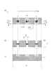
図7(a)〜(c)に、参考例として、アレイを構成する複数のターゲットのうち中央において放射線出力変動が観測されたアノードアレイ40の概略構成を示す。図7(a)は、アノードアレイを放射線放出に関わる開口側からみた平面図であり、図7(b)、(c)は、図7(a)に示すアノードアレイを、それぞれ、仮想断面V−V‘、仮想断面W−W’とで切り開いた断面図である。
7A to 7C show a schematic configuration of an
本参考例において、ターゲット層13と基材14とからなる積層型のターゲット15が配列方向Datにおいて、1/2×Latのピッチで3個配列され配列長Latをなしている。ターゲット15の間を、遮蔽体2と伝熱体3とからなる連結部1が連結してアノードアレイ40を構成している。
In the present reference example, three
遮蔽体2は、直方体の外形を有するタングステンからなるブロックからなり、ブロックの対向する2面間を円柱状に貫く開口部を有している。遮蔽体2の開口部の内壁と、ターゲット15の側面とが、不図示のろう材介して接続されている。伝熱体3は、遮蔽体2より高い熱伝導率を有する材料からなっている。
The
本参考例では、伝熱体3は、遮蔽体2を挟んでおり、アノードアレイ40内の配列方向Datにおいて不連続に連結部1を構成している。本参考例において、伝熱体3の長さLttは、ターゲット15の配列の長さLatより短く、また、ターゲット15のアレイピッチである1/2×Latよりも短く、離散的にアノードアレイ40内に配置されている。
In the present reference example, the
本発明者等の鋭意なる検討の結果、本参考例として記載したアレイ型放射線発生装置40の放射線出力変動は、複数のターゲット15を備えたアノードアレイ1のアレイ配列方向Datの熱抵抗に起因することが判った。
As a result of intensive studies by the present inventors, the radiation output fluctuation of the
より具体的には、遮蔽体2がアノードアレイの配列方向Datにおける伝熱のボトルネックとなっており、アレイ中央に位置するターゲット15の発熱が効果的に放熱されることを制限していることが、本発明者等により見出された。
More specifically, the
このような放射線出力安定性の低下は、アレイ方向の放射線出力不均一とする要因や、ターゲットに投入可能な陽極電流を制限し放射線発生装置の高出力化を制限する要因となるため改善が望まれていた。 Such reduction in radiation output stability is a factor that makes the radiation output non-uniform in the array direction and a factor that limits the anode current that can be input to the target and limits the high output of the radiation generator. It was rare.
そこで、本発明は、複数のターゲットに対応して遮蔽体を備えたアレイ型放射線発生装置において、アレイの配列方向の伝熱阻害に起因する放射線出力変動を抑制した信頼性の高い放射線発生装置、及び、放射線撮影装置を提供することを目的とする。 Therefore, the present invention provides a highly reliable radiation generator that suppresses radiation output fluctuation caused by heat transfer inhibition in the array direction of an array in an array type radiation generator provided with a shield corresponding to a plurality of targets, And it aims at providing a radiography apparatus.
本発明に係る第一の放射線発生装置は、複数の電子放出部を有するカソードアレイと、
それぞれが、前記複数の電子放出部のそれぞれに対応して配列され、前記電子放出部から放出された電子の照射により放射線を発生する複数のターゲットと、前記複数のターゲットを連結する連結部と、を有するアノードアレイと、を備える放射線発生装置であって、
前記連結部は、前記複数のターゲットに対応して配置された遮蔽部材と、前記遮蔽部材よりも熱伝導率が高い伝熱部材と、を備え、前記伝熱部材は、前記複数のターゲットの配列に沿って連続であり、
前記ターゲットは、前記電子放出部から放出された電子の照射により放射線を発生するターゲット層と前記ターゲット層を支持する基材とからなり、前記伝熱部材は、前記基材と接続する接続部を有することを特徴とする。
また、本発明に係る第二の放射線発生装置は、複数の電子放出部を有するカソードアレイと、それぞれが、前記複数の電子放出部のそれぞれに対応して配列され、前記電子放出部から放出された電子の照射により放射線を発生する複数のターゲットと、前記複数のターゲットを連結する連結部と、を有するアノードアレイと、を備える放射線発生装置であって、
前記連結部は、前記複数のターゲットに対応して配置された遮蔽部材と、前記遮蔽部材よりも熱伝導率が高い伝熱部材と、を備え、
前記伝熱部材は、前記複数のターゲットの配列に沿って連続であり、前記伝熱部材は、前記遮蔽部材の外周に接しているとともに、前記遮蔽部材を囲んでいることを特徴とする。
また、本発明に係る第三の放射線発生装置は、複数の電子放出部を有するカソードアレイと、それぞれが、前記複数の電子放出部のそれぞれに対応して配列され、前記電子放出部から放出された電子の照射により放射線を発生する複数のターゲットと、前記複数のターゲットを連結する連結部と、を有するアノードアレイと、を備える放射線発生装置であって、
前記連結部は、前記複数のターゲットに対応して配置された遮蔽部材と、前記遮蔽部材よりも熱伝導率が高い伝熱部材と、を備え、
前記伝熱部材は、前記複数のターゲットの配列に沿って連続であり、前記伝熱部材は、前記ターゲットに対する前記電子放出部の側と、前記ターゲットに対する前記電子放出部の反対側と、に位置していることを特徴とする。
A first radiation generating apparatus according to the present invention includes a cathode array having a plurality of electron emission portions,
Each of which is arranged corresponding to each of the plurality of electron emission portions, a plurality of targets for generating radiation by irradiation of electrons emitted from the electron emission portions, and a connection portion for connecting the plurality of targets, A radiation generator comprising: an anode array comprising:
The connecting portion includes a shielding member disposed corresponding to the plurality of targets, and a heat transfer member having a higher thermal conductivity than the shielding member, and the heat transfer member is an array of the plurality of targets . der continuous along the is,
The target includes a target layer that generates radiation by irradiation of electrons emitted from the electron emission portion and a base material that supports the target layer, and the heat transfer member includes a connection portion that is connected to the base material. and wherein the Rukoto that Yusuke.
Further, the second radiation generating apparatus according to the present invention includes a cathode array having a plurality of electron emission portions, each arranged corresponding to each of the plurality of electron emission portions, and emitted from the electron emission portions. A radiation generator comprising: an anode array having a plurality of targets that generate radiation by irradiation of electrons and a connecting portion that connects the plurality of targets;
The connecting portion includes a shielding member arranged corresponding to the plurality of targets, and a heat transfer member having a higher thermal conductivity than the shielding member,
The heat transfer member is continuous along the array of the plurality of targets, and the heat transfer member is in contact with the outer periphery of the shielding member and surrounds the shielding member.
Further, a third radiation generating apparatus according to the present invention includes a cathode array having a plurality of electron emission portions, each arranged corresponding to each of the plurality of electron emission portions, and emitted from the electron emission portions. A radiation generator comprising: an anode array having a plurality of targets that generate radiation by irradiation of electrons and a connecting portion that connects the plurality of targets;
The connecting portion includes a shielding member arranged corresponding to the plurality of targets, and a heat transfer member having a higher thermal conductivity than the shielding member,
The heat transfer member is continuous along the array of the plurality of targets, and the heat transfer member is positioned on the side of the electron emission portion with respect to the target and on the opposite side of the electron emission portion with respect to the target. It is characterized by that.
本発明の放射線発生装置は、複数のターゲットに対応した遮蔽体を備えたアノードアレイを備えているが、遮蔽体に起因する「ターゲットの配列方向の伝熱性の低下」を抑制し、放射線の出力変動を抑制した信頼性の高い放射線発生装置ならびに、放射線撮影装置を提供することが可能となる。 The radiation generating apparatus of the present invention includes an anode array including a shield corresponding to a plurality of targets, but suppresses “decrease in heat transfer in the target arrangement direction” caused by the shield, and outputs radiation. It is possible to provide a highly reliable radiation generating apparatus and a radiation imaging apparatus in which fluctuations are suppressed.
以下図面を参照して、本発明の放射線発生装置、並びに、放射線撮影装置についての実施形態を例示的に説明する。但し、本実施形態に記載されている構成の材質、寸法、形状、相対配置等は、特に記載がない限り、本発明の範囲を限定する趣旨のものではない。 Embodiments of a radiation generating apparatus and a radiation imaging apparatus of the present invention will be described below with reference to the drawings. However, the material, dimensions, shape, relative arrangement, and the like of the configuration described in the present embodiment are not intended to limit the scope of the present invention unless otherwise specified.
(放射線発生装置)
まず、図2を用いて、本発明の放射線発生装置の基本的な構成例について説明する。図2(a)は、駆動回路33を備えた放射線発生装置20の概略断面図であり、図2(b)は、図2(a)に図示された放射線発生装置20を、アノードアレイ10が配置された側からみた平面図である。
(Radiation generator)
First, a basic configuration example of the radiation generation apparatus of the present invention will be described with reference to FIG. 2A is a schematic cross-sectional view of the
本実施形態において、図2(a)に示すように、放射線発生装置20は、複数の電子放出部11を有するカソードアレイ12を備える。さらに、本実施形態の放射線発生装置20は、それぞれが、電子放出部11から放出複数の電子放出部11のそれぞれに対応して配列された複数のターゲット15と、複数のターゲット15を連結する連結部1と、を有するアノードアレイ10とを備える。
In the present embodiment, as shown in FIG. 2A, the
なお、連結部1は、複数のターゲット15に対応して配置された遮蔽体2と、遮蔽体2よりも熱伝導率が高い伝熱体3とを備えており、伝熱体3は、複数のターゲット15が配列される方向Datに沿って連続体で構成されている。連結部1についての詳細な説明は、後述する。
In addition, the
本実施形態においては、図2(a)、(b)に示すように、真鍮製の容器で構成された外囲器21を有している。カソードアレイ12は、外囲器21の内部23に収納され、アノードアレイ10は、ターゲット層13が電子放出部11と対向するように、外囲器21の開口部22に接続されている。
In the present embodiment, as shown in FIGS. 2A and 2B, an
さらに、本実施形態では、カソードアレイ12とアノードアレイ11に対して、それぞれ、陰極電位と陽極電位を規定する駆動回路33が電流導入端子34を介して接続されている。また、アノードアレイ10は外囲器21とともに、接地端子35に接続されている。即ち、本実施形態の放射線発生装置20は、陽極接地されている。
Furthermore, in the present embodiment, a
電子放出部11は、駆動回路33により制御される構造であれば特にその種類は制限されず、冷陰極、熱陰極のいずれの電子源により構成されても良い。かかる電子源としては、CNT、含浸型電子銃等を適用可能である。
The type of the
外囲器21は、その内部23または容器内面に、複数の電子放出部11と前記複数のターゲット層13とを収納または配置することができる容器である。
The
外囲器21の内部23は、電子の平均自由工程を確保する目的と、電子放出部11の電子放出特性の寿命を確保する目的とから、真空排気される。前述の目的から、外囲器21の内部23の真空度は、1×10⁻⁴ Pa以上1×10⁻⁸ Pa以下とすることが好ましい。
The inside 23 of the
従って、外囲器21は、耐大気圧強度を有した構造とすることが好ましい。また、本実施形態のアノードアレイ10は、外囲器21の部分を構成しているので、アノードアレイも耐大気圧強度を有していることが望まれる。
Therefore, it is preferable that the
なお、本実施形態において、アノードアレイ10は、外囲器21との接続により、物理的な接続による装置強度の確立、電気的な接続による装置駆動動作、伝熱的な接続による放熱促進の機能を果たしているとも捉えられる。
In the present embodiment, the
(放射線撮影装置)
本発明の放射線発生装置20は、図2(c)に示すように、放射線発生装置20から放出され被検体31を透過した放射線を検出する放射線検出装置32と、放射線発生装置32と放射線検出装置20とを連携制御するシステム制御装置36とを備えることにより、放射線撮影装置30を構成することが可能となる。
(Radiation imaging equipment)
As shown in FIG. 2C, the
(アノードアレイ)
次に、図1(a)−(c)の各図を用いて、本発明の放射線発生装置に適用可能なアノードアレイについて説明する。アノードアレイ10は、本発明において特徴的な構成要素である。
(Anode array)
Next, an anode array applicable to the radiation generator of the present invention will be described with reference to FIGS. 1 (a) to 1 (c). The
図1(a)はアノードアレイ10を放射線放出の為の開口を有する側から見た平面図である。図1(b)、(c)は、図1(a)のアノードアレイ10を、それぞれ、仮想断面P−P‘、仮想断面Q−Q’で切り開いた断面図である。
FIG. 1A is a plan view of the
本実施形態のターゲット15は、積層型のターゲットの構成をとり、ターゲット層13と、ターゲット層13を支持する基材14とから構成される。
The
積層型のターゲット15は、基材14の一方の面にターゲット層13を成膜することで形成される。ターゲット層13の形成方法は、特に限定されるものではないが、スパッタ法、蒸着法、パルスレーザ堆積法、CVD法等の気相成膜法が適用可能である。
The stacked
ターゲット層13は、ターゲット金属を含む薄膜である。ターゲット金属を構成する金属は、必要な線質、陽極―陰極間の加速電圧に応じて適宜選択可能であって、タングステン、モリブデン、タンタル等の原子番号40以上の金属元素が選択される。
The
また、ターゲット層13は、ターゲット金属を純金属として含む形態に限定されず、合金、窒化物、炭化物、酸化物の形態とすることも可能である。
Further, the
基材14は、放射線発生装置の動作温度、または、放射線発生装置の製造時温度に耐熱性のある材料から構成することが望ましく、ベリリウム、黒鉛、ダイアモンド等が適用可能である。耐熱性、熱伝導性、放射線自己減衰の観点からは、ダイアモンドを基材14とすることがより好ましい。
The
このように、ターゲット15を積層型の構成とすることは、放射線発生、放熱または放射線自己減衰抑制とを機能分離し、各構成要素の材料を最適化できる利点を有する。
As described above, the
一方で、ダイアモンドからなる基材14に備える実施形態においては、製造上および部材価格の観点から、特許文献3に記載のようにアノードアレイを一つの板状の基材で構成することは現実的ではない。従って、基材14にダイアモンドを用いてアノードアレイを構成する場合は、図1に示すように、ダイアモンドからなる基材14を離散的に配置し、隣接するダイアモンドからなる基材14間を連結部1により連結する構成をとることが現実的である。
On the other hand, in the embodiment provided for the
従って、本発明の解決すべき課題の対象となるアレイ型放射線発生装置は、アノードアレイが、複数の積層型のターゲットとそれらを連結する連結部とから構成され、さらに、連結部が複数のターゲットの各々に対応して遮蔽体を備えている放射線発生装置に関するものである。 Therefore, in the array-type radiation generating apparatus that is the subject of the present invention, the anode array includes a plurality of stacked targets and a connecting portion that connects them, and the connecting portion includes a plurality of targets. The present invention relates to a radiation generating apparatus provided with a shield corresponding to each of the above.
次に、本実施形態のアノードアレイ10の特徴的な構成要素である、遮蔽体2と伝熱体3とから構成される連結部1について説明する。
Next, the
図1(b)に示すように、ターゲット15が配列する中心軸を通る断面P−P‘においては、アノードアレイ10の伝熱体3は、ターゲット15に対応して設けられた遮蔽体2により不連続に分断されて配置されている。しかしながら、図1(a)または図1(c)に示すように、伝熱体3は、ターゲット15の配列方向Datに沿って、その配列の長さであるLatよりも長い範囲に渡って、長さLttを有して連続体で構成されている。
As shown in FIG. 1B, in the cross section PP ′ passing through the central axis where the
伝熱機構としては、直列な伝熱体3の伝熱経路に、間隔1/2×Latを隔てた位置に基材14の熱抵抗を介して熱源が並列に3箇所接続されている等価回路で説明される。
As a heat transfer mechanism, an equivalent circuit in which three heat sources are connected in parallel to the heat transfer path of the
本実施形態では、ターゲット15の配列方向Datとその逆方向への熱伝達を阻害するように、熱抵抗が大な遮蔽体が配置されていないので、配列中央のターゲット15からの発熱は効果的に配列終端に向かって放熱される。この点が、本実施形態のアノードアレイ10が、図7に記載の放射線の出力変動が観測されたアノードアレイ40との相違点である。
In the present embodiment, since a shield having a large thermal resistance is not disposed so as to inhibit heat transfer in the array direction Dat of the
遮蔽体2は、ターゲット層13に対して電子放出部11側に配置された後方遮蔽体2bと、ターゲット層13に対して電子放出部11側とは反対側に位置する前方遮蔽体2fとから構成することが可能である。
The
遮蔽体2は、ターゲット層13において発生する放射線の線質、強度を考慮して、比重が大きな材料が適宜選択可能であるが、得られる放射線遮蔽性能と調達価格のバランスからは、タングステン(比重19000kg/m3、熱伝導率115W/m/Kともに1200K)を主成分として含有することが好ましい。
For the
遮蔽体2として後方遮蔽体を備えている実施形態においては、ターゲット層13を構成するターゲット金属を、遮蔽体2を構成する材料とすることで、ターゲット層13における反射電子による線質汚染の影響を抑制することが可能となる。
In the embodiment in which a rear shield is provided as the
本発明においては、遮蔽体2を、伝熱体3よりも高い比重を有する材料から構成することで、放射線遮蔽性能を、伝熱体3が担う放熱性能と機能分離し、アノードアレイ10の高耐熱性と小型化に貢献する効果を有する。
In the present invention, the
伝熱体3は、遮蔽体2より熱伝導率が高い材料から構成され、得られる熱伝導性と調達価格のバランスを考慮して、銅(比重8460kg/m3、熱伝導率342W/m/Kともに1200K)、銀(比重9824kg/m3、熱伝導率358W/m/Kともに1200K)、またはそれらの合金を主成分として含有することが好ましい。
The
なお、図6(a)に、図1(a)に示した基材14と連結部1との接続部近傍の部分拡大図示す。図6(a)では、図1(a)では省略したろう材26が示されている。図6(a)に示すように、本実施形態のアノードアレイ10においては、基材14の側面と伝熱体3とが、ろう材26を介して接続される接続部25を形成している。
6A is a partially enlarged view of the vicinity of the connection portion between the
ろう材26は、銀ろうを用いることにより、遮蔽体2よりも高い熱伝導率(150〜200程度W/m/K)とすることが可能である。ろう材26は、遮蔽体2と異なり、連結部1に占める体積は十分小さく、図6(a)のような配置をとった場合においても、伝熱体3の連続性を失うことは無い。
The
(その他の実施形態)
次に、本発明の放射線発生装置に適用可能なアノードアレイ10のその他の実施形態について、図3、図4、図5、及び、図6の各図を用いて説明する。
(Other embodiments)
Next, other embodiments of the
図3(a)〜(c)に示したアノードアレイ10は、図1(a)〜(c)に図示したアノードアレイ10とは、ターゲット15の基材14と連結部1との接続形態において相違する。図6(b)に、図3(b)に示した基材14と連結部1との接続部近傍の部分拡大図示す。図6(b)では、図3(b)では省略したろう材26が示されている。
The
図6(b)に示すように、本実施形態のアノードアレイ10においては、基材14の側面と伝熱体3とが、ろう材26と遮蔽体2とを介して接続され接続部25を形成しており、遮蔽体2を介している点が、図6(a)に示した接続部25と相違する。
As shown in FIG. 6B, in the
なお、図3(b)、(c)は、それぞれ、図3(a)に平面図として示したアノードアレイ10を仮想断面R−R‘、仮想断面S−S’で切り開いた断面図である。
3B and 3C are cross-sectional views in which the
伝熱機構としては、直列な伝熱体3の伝熱経路に、間隔1/2×Latを隔てて基材14と遮蔽体2との直列の熱抵抗を介して熱源が並列に3箇所接続されている等価回路で説明される。
As a heat transfer mechanism, three heat sources are connected in parallel to the heat transfer path of the serial
伝熱機構としては、直列な伝熱体3の伝熱経路の3箇所に、熱源から並列に接続される伝熱経路において遮蔽体の熱抵抗を介する点において、図1に記載のアノードアレイ10と相違し、本実施形態のアノードアレイ10の放熱性はやや劣る。しかしながら、本実施形態のアノードアレイ10においても、図3(a)、(c)に示すように、伝熱体3が、ターゲット15の配列方向Datに沿って、その配列の長さであるLatよりも長い範囲に渡って、長さLttを有して連続体で構成されており、本発明の特徴的な構成を備えている。
As the heat transfer mechanism, the
図4(a)〜(c)に示したアノードアレイ10は、図1(a)〜(c)に図示したアノードアレイ10とは、遮蔽体2の形成範囲において相違する。図4(b)、(c)は、それぞれ、図4(a)に平面図として示したアノードアレイ10を仮想断面T−T‘、仮想断面U−U’で切り開いた断面図である。
The
伝熱機構としては、直列な伝熱体3の伝熱経路に、間隔1/2×Latを隔てて基材14の熱抵抗を介して熱源が並列に3箇所接続されている等価回路で説明され、図1に記載のアノードアレイ10と同等の伝熱性能を、本実施形態のアノードアレイ10は発現する。
The heat transfer mechanism is described as an equivalent circuit in which three heat sources are connected in parallel to the heat transfer path of the
図5に示したアノードアレイ10は、図1に図示したアノードアレイ10のアレイの配列を変形したその他の実施形態である。図1に示したアノードアレイ10が、一次元配列であったのに対して、図5に示すように本実施形態のアノードアレイ10は、二次元配列をなしている点が相違する。本実施形態においても、伝熱体3は、配列方向Dar(行方向)と配列方向Dac(列方向)における、それぞれの、配列の長さLar、Lacより長い範囲において、それぞれ、長さLtr、Ltcを有して連続体で構成されている。
The
このように、本発明の放射線発生装置に適用されるアノードアレイを構成する複数のターゲットの配列は一次元配列に必ずしも限定されない、また、配列を構成する方向性においても、直交するマトリクス、直線状配列であることにも限定されず、他の任意の配列形態を有したアノードアレイに適用可能である。 Thus, the arrangement of the plurality of targets constituting the anode array applied to the radiation generating apparatus of the present invention is not necessarily limited to a one-dimensional arrangement, and also in the directionality constituting the arrangement, an orthogonal matrix, a linear shape The present invention is not limited to the arrangement, and can be applied to an anode array having any other arrangement form.
(実施例1)
まず、図1に概略構成を示すアノードアレイ10を以下のようにして作成した。
Example 1
First, an
まず、板厚1mm、直径6mmのディスク状のダイアモンドからなる基材14を用意した。次に、基材14に対して、有機溶剤による脱脂とオゾンアッシャ装置による残留有機物の除去を行った。使用した基材14の25℃における熱伝導率は、1950(W/m/K)であった。
First, a
次に、アルゴンをキャリアガスとしてスパッタ法により、基材14の一方の円形の面に対して、層厚8μm、直径3.5mmのターゲット層14を形成した。さらに、クロムからなる不図示の環状の電極をターゲット層14の周辺から基材14周縁にかけてスパッタ法により形成した。クロムからなる電極は、基材14の側面にまで形成されている事を確認した。以上の工程により、積層型のターゲット15を3個形成した。
Next, a
次に、機械加工で形成した開口を備えた遮蔽体2を3個用意した後、配列ピッチ12mmで遮蔽体2を配置し、さらに、3つの遮蔽体2の周囲に溶融銅を流し込んで鋳込み一体化して、最後に、連結部の外周面となる部分を機械研磨により整形した。このようにして、図1に示すような、銅からなる伝熱体3とタングステンからなる遮蔽体2とからなる連結部1を用意した。使用した伝熱体3と遮蔽体2の25℃における熱伝導率は、それぞれ、397(W/m/K)、177(W/m/K)であった。遮蔽体2は、前方遮蔽体2fと後方遮蔽体2bのそれぞれにおいて、2mm厚の壁厚を有した筒形状であった。
Next, after preparing three shielding
次に、連結部1に対して、ターゲット15を不図示のろう材26からなるろう材26を用いて、図1(b)に示すように、連結部2の開口部の伝熱体3が露出している部分に接続した。以上のようにして、配列ピッチが12mmのアノードアレイ10を作成した。使用したろう材の25℃における熱伝導率は、170(W/m/K)であった。
Next, as shown in FIG. 1B, the
本実施例のアノードアレイ10の連結部1とターゲット15との接続部25近傍の部分拡大図を、図6(a)に図示する。図6(a)に示すように、基材14から伝熱体3との距離90〜100μmの間隙は、ろう材26を介して伝熱的に接続されていた。
FIG. 6A shows a partially enlarged view of the vicinity of the connecting
次に、含侵型の熱電子銃を不図示のホルダーに固定し、アノードアレイ10と同じ配列ピッチで電子放出部11を3個備えたカソードアレイ12を形成した。
Next, an impregnated type thermoelectron gun was fixed to a holder (not shown) to form a
次に、不図示の固定冶具を用いて、SUS304製の外囲器21の内部23にカソードアレイ12を固定し、さらに、外囲器21の開口部22にアノードアレイ10を不図示の銀ろうを用いて接続した。次に、外囲器21に予め備えつけておいた電流導入端子34と、カソードアレイ12とアノードアレイ10とのそれぞれを電気的に接続した。なお、アノードアレイ10と外囲器21は接地端子35に電気的に接続した。
Next, using a fixing jig (not shown), the
次に、不図示の排気管と真空ポンプと不図示のゲッタとを用いて、外囲器21の内部23を真空排気した。外囲器21の到達真空度は、2×10⁻⁶ Paであった。
Next, the inside 23 of the
さらに、電流導入端子34に、駆動回路33を接続し、図2(a)に示すような放射線発生装置20を作成した。
Furthermore, the
次に、放射線発生装置20の駆動安定性評価を以下のようにして行った。駆動安定性の評価における駆動回路33の駆動条件は、加速電圧を+100kV、ターゲット層15に照射される電子電流密度を3mA/mm2、電子照射時間と非照射時間とを交互に、それぞれ2秒、198秒のセットとして繰り返すパルス駆動とした。さらに、配列方向Datに並ぶ3個のターゲット15に対して順次パルス駆動されるように、カソードアレイ12を点順次駆動した。
Next, drive stability evaluation of the
なお、放射線出力強度の安定性評価に際し、ターゲット層15から接地電極35に流れる電流を計測して、不図示の負帰還回路により、陽極電流を1%以内の変動値とするように制御した。
In evaluating the stability of the radiation output intensity, the current flowing from the
放射線出力強度は、アノードアレイの各ターゲット15から1m前方の位置に、ピンホールを介して設置した放射線線量計26を用いて、検出時間1秒間の平均値を用いた。安定性評価は、100時間経過後の放射線出力強度を、初期の放射線出力強度で規格化した変動率で評価した。
As the radiation output intensity, an average value for a detection time of 1 second was used using a
本実施例の放射線発生装置20の放射線出力変動は、図1に示すアノードアレイ10のターゲット15のうち左から順に、0.98、0.99、0.99であった。
The radiation output fluctuations of the
本実施例の透過型ターゲット9を備えた放射線発生装置13は、長時間の駆動履歴を経た場合においても、アレイ配列方向において顕著な放射線出力変動も認められず、安定した放射線出力強度が得られることが確認された。
The
本実施例のアノードアレイ10においては、図1に示すように、配列方向Datに沿って、伝熱体3の形状は連続に位置し、遮蔽体2とターゲット15とは、それぞれ離散的に配置されていることにより、放射線の出力変動の発生が抑制されていたと推定された。
In the
なお、放射線発生装置20は、駆動安定性の駆動評価期間中に、放電せずに安定的に駆動していていることが確認された。
It was confirmed that the
(実施例2)
本実施例においては、図4に記載のアノードアレイ10を用いたこと以外は、実施例1と同様にして放射線発生装置20を作成した。
(Example 2)
In this example, a
本実施例の放射線発生装置20の放射線出力変動は、図4に示すアノードアレイ10のターゲット15のうち左から順に、0.98、0.98、0.99であった。
The radiation output fluctuations of the
本実施例においても、実施例1と同様にして、アノード配列方向において顕著な放射線の出力変動が認められず、信頼性の高い放射線発生装置20であることが確認された。
Also in this example, as in Example 1, no significant radiation output fluctuation was observed in the anode arrangement direction, and it was confirmed that the
(実施例3)
本実施例においては、実施例1に記載の放射線発生装置20を用いて、図2(b)に記載の放射線撮影装置30を作成した。
(Example 3)
In the present example, the
本実施例の放射線撮影装置においては、アレイ配列方向の放射線出力変動が抑制された放射線発生装置20を備えることにより、SN比の高いX線撮影画像を取得することができた。
In the radiation imaging apparatus of the present embodiment, an X-ray imaging image having a high S / N ratio could be acquired by including the
11 電子放出部
12 カソードアレイ
13 ターゲット層
14 基材
15 ターゲット
16 電子線
17 放射線
1 連結部
2 遮蔽体
3 伝熱体
10 アノードアレイ
20 放射線発生装置
DESCRIPTION OF
Claims (22)
それぞれが、前記複数の電子放出部のそれぞれに対応して配列され、前記電子放出部から放出された電子の照射により放射線を発生する複数のターゲットと、前記複数のターゲットを連結する連結部と、を有するアノードアレイと、
を備える放射線発生装置であって、
前記連結部は、前記複数のターゲットに対応して配置された遮蔽部材と、前記遮蔽部材よりも熱伝導率が高い伝熱部材と、を備え、
前記伝熱部材は、前記複数のターゲットの配列に沿って連続であり、
前記ターゲットは、前記電子放出部から放出された電子の照射により放射線を発生するターゲット層と前記ターゲット層を支持する基材とからなり、前記伝熱部材は、前記基材と接続する接続部を有することを特徴とする放射線発生装置。 A cathode array having a plurality of electron emitting portions;
Each of which is arranged corresponding to each of the plurality of electron emission portions, a plurality of targets for generating radiation by irradiation of electrons emitted from the electron emission portions, and a connection portion for connecting the plurality of targets, An anode array having
A radiation generator comprising:
The connecting portion includes a shielding member arranged corresponding to the plurality of targets, and a heat transfer member having a higher thermal conductivity than the shielding member,
The heat transfer member state, and are continuous along the array of the plurality of targets,
The target includes a target layer that generates radiation by irradiation of electrons emitted from the electron emission portion and a base material that supports the target layer, and the heat transfer member includes a connection portion that is connected to the base material. radiation generating apparatus according to claim Rukoto to Yusuke.
それぞれが、前記複数の電子放出部のそれぞれに対応して配列され、前記電子放出部から放出された電子の照射により放射線を発生する複数のターゲットと、前記複数のターゲットを連結する連結部と、を有するアノードアレイと、
を備える放射線発生装置であって、
前記連結部は、前記複数のターゲットに対応して配置された遮蔽部材と、前記遮蔽部材よりも熱伝導率が高い伝熱部材と、を備え、
前記伝熱部材は、前記複数のターゲットの配列に沿って連続であり、前記伝熱部材は、前記遮蔽部材の外周に接しているとともに、前記遮蔽部材を囲んでいることを特徴とする放射線発生装置。 A cathode array having a plurality of electron emitting portions;
Each of which is arranged corresponding to each of the plurality of electron emission portions, a plurality of targets for generating radiation by irradiation of electrons emitted from the electron emission portions, and a connection portion for connecting the plurality of targets, An anode array having
A radiation generator comprising:
The connecting portion includes a shielding member arranged corresponding to the plurality of targets, and a heat transfer member having a higher thermal conductivity than the shielding member,
The heat transfer member, said plurality of Der continuous along the sequence of the target is, the heat transfer member, together in contact with the outer periphery of the shield member, wherein Rukoto surrounds the shielding member Radiation generator.
それぞれが、前記複数の電子放出部のそれぞれに対応して配列され、前記電子放出部から放出された電子の照射により放射線を発生する複数のターゲットと、前記複数のターゲットを連結する連結部と、を有するアノードアレイと、
を備える放射線発生装置であって、
前記連結部は、前記複数のターゲットに対応して配置された遮蔽部材と、前記遮蔽部材よりも熱伝導率が高い伝熱部材と、を備え、
前記伝熱部材は、前記複数のターゲットの配列に沿って連続であり、前記伝熱部材は、前記ターゲットに対する前記電子放出部の側と、前記ターゲットに対する前記電子放出部の反対側と、に位置していることを特徴とする放射線発生装置。 A cathode array having a plurality of electron emitting portions;
Each of which is arranged corresponding to each of the plurality of electron emission portions, a plurality of targets for generating radiation by irradiation of electrons emitted from the electron emission portions, and a connection portion for connecting the plurality of targets, An anode array having
A radiation generator comprising:
The connecting portion includes a shielding member arranged corresponding to the plurality of targets, and a heat transfer member having a higher thermal conductivity than the shielding member,
The heat transfer member state, and are continuous along the array of the plurality of targets, the heat transfer member has a side of the electron-emitting portion with respect to the target, and the opposite side of the electron-emitting portion with respect to the target, the position to have a radiation generating apparatus according to claim Rukoto.
前記放射線発生装置から放出され、被検部材を透過した放射線を検出する放射線検出装置と、
前記放射線発生装置と前記放射線検出装置とを連携制御する制御装置とを備えることを特徴とする放射線撮影装置。 The radiation generator according to any one of claims 1 to 21 ,
A radiation detection device that detects radiation emitted from the radiation generation device and transmitted through a test member;
A radiation imaging apparatus comprising: a control device that controls the radiation generation device and the radiation detection device in a coordinated manner.
Priority Applications (4)
| Application Number | Priority Date | Filing Date | Title |
|---|---|---|---|
| JP2013025729A JP6116274B2 (en) | 2013-02-13 | 2013-02-13 | Radiation generator and radiation imaging apparatus including the radiation generator |
| EP14152983.4A EP2768009B1 (en) | 2013-02-13 | 2014-01-29 | Radiation generating apparatus and radiography system including the radiation generating apparatus |
| US14/171,452 US9281157B2 (en) | 2013-02-13 | 2014-02-03 | Radiation generating apparatus and radiography system including the radiation generating apparatus |
| CN201410049216.7A CN103985622B (en) | 2013-02-13 | 2014-02-13 | Radioactive ray produce equipment and comprise the radiography system that this radioactive ray produce equipment |
Applications Claiming Priority (1)
| Application Number | Priority Date | Filing Date | Title |
|---|---|---|---|
| JP2013025729A JP6116274B2 (en) | 2013-02-13 | 2013-02-13 | Radiation generator and radiation imaging apparatus including the radiation generator |
Publications (3)
| Publication Number | Publication Date |
|---|---|
| JP2014154499A JP2014154499A (en) | 2014-08-25 |
| JP2014154499A5 JP2014154499A5 (en) | 2016-03-17 |
| JP6116274B2 true JP6116274B2 (en) | 2017-04-19 |
Family
ID=50023446
Family Applications (1)
| Application Number | Title | Priority Date | Filing Date |
|---|---|---|---|
| JP2013025729A Active JP6116274B2 (en) | 2013-02-13 | 2013-02-13 | Radiation generator and radiation imaging apparatus including the radiation generator |
Country Status (4)
| Country | Link |
|---|---|
| US (1) | US9281157B2 (en) |
| EP (1) | EP2768009B1 (en) |
| JP (1) | JP6116274B2 (en) |
| CN (1) | CN103985622B (en) |
Families Citing this family (7)
| Publication number | Priority date | Publication date | Assignee | Title |
|---|---|---|---|---|
| KR20150051820A (en) * | 2013-11-05 | 2015-05-13 | 삼성전자주식회사 | Penetrative plate X-ray generating apparatus and X-ray imaging system |
| GB2531326B (en) * | 2014-10-16 | 2020-08-05 | Adaptix Ltd | An X-Ray emitter panel and a method of designing such an X-Ray emitter panel |
| DE102015213285A1 (en) | 2015-07-15 | 2017-02-02 | Siemens Healthcare Gmbh | X-ray device for inverse computed tomography |
| WO2017130013A1 (en) * | 2016-01-25 | 2017-08-03 | Adaptix Ltd | Medical imaging system having an array of distributed x-ray generators |
| CN109216138B (en) * | 2017-06-30 | 2024-07-26 | 同方威视技术股份有限公司 | X-ray tube |
| KR101966794B1 (en) * | 2017-07-12 | 2019-08-27 | (주)선재하이테크 | X-ray tube for improving electron focusing |
| EP4060713A4 (en) * | 2019-11-11 | 2023-12-13 | Canon Electron Tubes & Devices Co., Ltd. | X-ray tube and method for manufacturing x-ray tube |
Family Cites Families (11)
| Publication number | Priority date | Publication date | Assignee | Title |
|---|---|---|---|---|
| US5148462A (en) * | 1991-04-08 | 1992-09-15 | Moltech Corporation | High efficiency X-ray anode sources |
| DE19934987B4 (en) | 1999-07-26 | 2004-11-11 | Fraunhofer-Gesellschaft zur Förderung der angewandten Forschung e.V. | X-ray anode and its use |
| US6661876B2 (en) | 2001-07-30 | 2003-12-09 | Moxtek, Inc. | Mobile miniature X-ray source |
| JP4878311B2 (en) | 2006-03-03 | 2012-02-15 | キヤノン株式会社 | Multi X-ray generator |
| JP2009545840A (en) | 2006-04-20 | 2009-12-24 | マルチディメンショナル イメージング,インコーポレイテッド | X-ray tube with transmissive anode |
| JP5294653B2 (en) * | 2008-02-28 | 2013-09-18 | キヤノン株式会社 | Multi X-ray generator and X-ray imaging apparatus |
| US7976218B2 (en) * | 2008-10-16 | 2011-07-12 | General Electric Company | Apparatus for providing shielding in a multispot x-ray source and method of making same |
| JP5641916B2 (en) | 2010-02-23 | 2014-12-17 | キヤノン株式会社 | Radiation generator and radiation imaging system |
| JP5455880B2 (en) | 2010-12-10 | 2014-03-26 | キヤノン株式会社 | Radiation generating tube, radiation generating apparatus and radiographic apparatus |
| JP2012138203A (en) * | 2010-12-24 | 2012-07-19 | Aet Inc | X-ray generation device and x-ray irradiation device using group of x-ray generation device |
| US9508524B2 (en) * | 2011-08-05 | 2016-11-29 | Canon Kabushiki Kaisha | Radiation generating apparatus and radiation imaging apparatus |
-
2013
- 2013-02-13 JP JP2013025729A patent/JP6116274B2/en active Active
-
2014
- 2014-01-29 EP EP14152983.4A patent/EP2768009B1/en not_active Not-in-force
- 2014-02-03 US US14/171,452 patent/US9281157B2/en not_active Expired - Fee Related
- 2014-02-13 CN CN201410049216.7A patent/CN103985622B/en not_active Expired - Fee Related
Also Published As
| Publication number | Publication date |
|---|---|
| EP2768009B1 (en) | 2018-07-18 |
| CN103985622B (en) | 2016-10-05 |
| CN103985622A (en) | 2014-08-13 |
| JP2014154499A (en) | 2014-08-25 |
| US9281157B2 (en) | 2016-03-08 |
| EP2768009A3 (en) | 2017-03-08 |
| EP2768009A2 (en) | 2014-08-20 |
| US20140226787A1 (en) | 2014-08-14 |
Similar Documents
| Publication | Publication Date | Title |
|---|---|---|
| JP6116274B2 (en) | Radiation generator and radiation imaging apparatus including the radiation generator | |
| JP5812700B2 (en) | X-ray emission target, X-ray generator tube and X-ray generator | |
| EP2430638B1 (en) | X-ray source with a plurality of electron emitters and method of use | |
| US9408577B2 (en) | Multiradiation generation apparatus and radiation imaging system utilizing dual-purpose radiation sources | |
| JP5911323B2 (en) | Target structure, radiation generating apparatus including the target structure, and radiation imaging system | |
| US20090041198A1 (en) | Highly collimated and temporally variable x-ray beams | |
| JP2015002074A (en) | Transmission type target, radiation generating tube including the transmission type target, radiation generating device and radiography device | |
| JP6316019B2 (en) | X-ray generating tube, X-ray generating apparatus and X-ray imaging system provided with the X-ray generating tube | |
| KR20040085163A (en) | Large-Area Individually Addressable Multi-Beam X-Ray System | |
| JP6552289B2 (en) | X-ray generator tube, X-ray generator, X-ray imaging system | |
| JP6388400B2 (en) | X-ray generator and X-ray imaging system using the same | |
| JP6619916B1 (en) | X-ray generator tube, X-ray generator and X-ray imaging apparatus | |
| CN109473329A (en) | A kind of spatial coherence x-ray source of surface launching transmission-type array structure | |
| JP2013051165A (en) | Transmission x-ray generator | |
| US9484177B2 (en) | Longitudinal high dose output, through transmission target X-ray system and methods of use | |
| JP2019519900A (en) | Cathode assembly for use in generating x-rays | |
| JP2014154499A5 (en) | ||
| CN109698105B (en) | High dose delivery, transmission and reflection target X-ray system and method of use | |
| US20140126701A1 (en) | X-ray emitting target and x-ray emitting device | |
| JP2017168216A (en) | X-rat target and x-ray generating apparatus having the same | |
| JP6153314B2 (en) | X-ray transmission type target and manufacturing method thereof | |
| JP2000082430A (en) | Target for x-ray generation and x-ray tube using the same | |
| JP2015173045A (en) | Radiation tube, and radiation generator and radiography system using the radiation tube | |
| CN209232723U (en) | A kind of spatial coherence x-ray source of surface launching transmission-type array structure | |
| JP6381756B2 (en) | Transmission type target, radiation generating tube including the transmission type target, radiation generation apparatus, and radiation imaging apparatus |
Legal Events
| Date | Code | Title | Description |
|---|---|---|---|
| A521 | Request for written amendment filed |
Free format text: JAPANESE INTERMEDIATE CODE: A523 Effective date: 20160202 |
|
| A621 | Written request for application examination |
Free format text: JAPANESE INTERMEDIATE CODE: A621 Effective date: 20160202 |
|
| A977 | Report on retrieval |
Free format text: JAPANESE INTERMEDIATE CODE: A971007 Effective date: 20161125 |
|
| A131 | Notification of reasons for refusal |
Free format text: JAPANESE INTERMEDIATE CODE: A131 Effective date: 20161206 |
|
| A521 | Request for written amendment filed |
Free format text: JAPANESE INTERMEDIATE CODE: A523 Effective date: 20170202 |
|
| TRDD | Decision of grant or rejection written | ||
| A01 | Written decision to grant a patent or to grant a registration (utility model) |
Free format text: JAPANESE INTERMEDIATE CODE: A01 Effective date: 20170221 |
|
| A61 | First payment of annual fees (during grant procedure) |
Free format text: JAPANESE INTERMEDIATE CODE: A61 Effective date: 20170321 |
|
| R151 | Written notification of patent or utility model registration |
Ref document number: 6116274 Country of ref document: JP Free format text: JAPANESE INTERMEDIATE CODE: R151 |