JP6388400B2 - X-ray generator and X-ray imaging system using the same - Google Patents
X-ray generator and X-ray imaging system using the same Download PDFInfo
- Publication number
- JP6388400B2 JP6388400B2 JP2014229592A JP2014229592A JP6388400B2 JP 6388400 B2 JP6388400 B2 JP 6388400B2 JP 2014229592 A JP2014229592 A JP 2014229592A JP 2014229592 A JP2014229592 A JP 2014229592A JP 6388400 B2 JP6388400 B2 JP 6388400B2
- Authority
- JP
- Japan
- Prior art keywords
- anode member
- ray generator
- tube
- target
- ray
- Prior art date
- Legal status (The legal status is an assumption and is not a legal conclusion. Google has not performed a legal analysis and makes no representation as to the accuracy of the status listed.)
- Active
Links
Images


Classifications
-
- H—ELECTRICITY
- H01—ELECTRIC ELEMENTS
- H01J—ELECTRIC DISCHARGE TUBES OR DISCHARGE LAMPS
- H01J35/00—X-ray tubes
- H01J35/02—Details
- H01J35/16—Vessels; Containers; Shields associated therewith
- H01J35/18—Windows
- H01J35/186—Windows used as targets or X-ray converters
-
- H—ELECTRICITY
- H01—ELECTRIC ELEMENTS
- H01J—ELECTRIC DISCHARGE TUBES OR DISCHARGE LAMPS
- H01J35/00—X-ray tubes
- H01J35/02—Details
- H01J35/04—Electrodes ; Mutual position thereof; Constructional adaptations therefor
- H01J35/08—Anodes; Anti cathodes
- H01J35/112—Non-rotating anodes
- H01J35/116—Transmissive anodes
Description
本発明は、例えば医療機器、非破壊検査装置等に適用可能なX線発生装置、及びこれを用いたX線撮影システムに関する。 The present invention relates to an X-ray generator that can be applied to, for example, medical devices, non-destructive inspection apparatuses, and the like, and an X-ray imaging system using the same.
一般に、X線発生装置は、X線源として、X線発生管を内蔵している。X線発生管は、絶縁管の開口の一方に陰極を、他方に陽極を取り付けた真空容器で構成され、陰極には電子放出源が接続され、陽極はターゲットを備えている。X線発生管は、陰極と陽極との間に高電圧を印加することにより、電子放出源から放出される電子線をターゲットに照射し、X線を発生させている。 In general, an X-ray generation apparatus incorporates an X-ray generation tube as an X-ray source. The X-ray generating tube is composed of a vacuum vessel in which a cathode is attached to one of the openings of an insulating tube and an anode is attached to the other. An electron emission source is connected to the cathode, and the anode includes a target. The X-ray generator irradiates a target with an electron beam emitted from an electron emission source by applying a high voltage between the cathode and the anode to generate X-rays.
特許文献1には前記X線発生装置の一例として、X線発生装置の収納容器である金属筐体の出力開口部と前記X線発生管の出力窓の中心位置を一致させながら、前記金属筐体に前記陽極を固定した構成が開示されている。特許文献1では、係る構成とすることで、出力窓から放射するX線を前記X線発生装置外へ照射する。また係る構成とすることで、X線発生管のターゲットから該ターゲットを保持している陽極部材、さらにはX線発生装置の金属筺体までは熱的、及び電気的に接続された状態となり、電子線の照射によって温度上昇したターゲットの放熱を図っている。
In
特許文献1に開示された構成のX線発生装置では、X線を照射時、電子がターゲットに衝突することで発生するX線以外の電子エネルギーは熱に変換され、ターゲットから陽極部材を介して金属筺体へと放熱する構成となっている。一方で前記電子を放出する電子放出源の電子放出部も発熱し、その発熱量の一部は真空容器に対して陽極部材と対向位置にある陰極部材へも放熱されるが、その他の発熱量は電子放出部と近接している陽極部材へ放射され、陽極部材を介して金属筐体に放熱される。よって陽極部材から金属筐体へ放熱する熱伝導経路上には、ターゲットからの発熱量分と電子放出部での発熱量の一部が熱伝導することになり、ターゲットの放熱が十分にできなくなる恐れがあった。
In the X-ray generator having the configuration disclosed in
ターゲットの放熱が十分に行えず、ターゲットが高温になった場合には、ターゲット層の剥離や溶解、蒸発、支持基板にクラックが発生するといったターゲットの損傷を招く恐れがあり、その結果、X線出力の変動や低下が生じる場合があった。 If the target cannot sufficiently dissipate heat and the temperature of the target becomes high, it may cause damage to the target such as peeling or dissolution of the target layer, evaporation, and cracks in the support substrate. In some cases, the output fluctuated or decreased.
本発明の課題は、陽極部材が収納容器の一部を構成する透過型のX線発生装置において、ターゲットの放熱性を高め、X線出力の安定化を図ることにある。さらに、本発明は、係るX線発生装置を用いて、信頼性の高いX線撮影システムを提供することにある。 An object of the present invention is to improve the heat dissipation of a target and stabilize the X-ray output in a transmission type X-ray generator in which an anode member constitutes a part of a storage container. Furthermore, this invention is providing the reliable X-ray imaging system using the X-ray generator which concerns.
上記課題を解決するための本発明の第1は、電子の照射によりX線を発生する透過型のターゲット及び前記ターゲットを保持する陽極部材を有する陽極と、前記ターゲットに電子を照射する電子放出源及び前記電子放出源に接続される陰極部材を有する陰極と、前記陽極部材と前記陰極部材との間に配置され前記陽極部材と前記陰極部材のそれぞれと気密接合される絶縁管と、を備えたX線発生管、及び、前記陽極部材に接続され前記X線発生管を収納する導電性の収納容器、を備えたX線発生装置であって、
前記陽極部材は、前記ターゲットを保持し、前記収納容器に電気的に接続される外側陽極部材と、前記絶縁管の管軸方向において、前記外側陽極部材と前記電子放出源との間に位置し、前記絶縁管に接合される内側陽極部材と、を備え、
管径方向における前記絶縁管の外側において、前記内側陽極部材が前記外側陽極部材と伝熱的に接続されていることを特徴とする。
また、本発明の第2は、透過型のターゲット及び前記ターゲットに接続される陽極部材を有する陽極と、電子放出源及び前記電子放出源に接続される陰極部材を有する陰極と、前記陽極部材と前記陰極部材との間に配置され前記陽極部材と前記陰極部材のそれぞれと気密接合される絶縁管と、を備えたX線発生管、及び、前記陽極部材に接続され前記X線発生管と絶縁性液体とを収納する導電性の収納容器、を備えたX線発生装置であって、
前記陽極部材は、前記ターゲットから前記収納容器に熱を伝導する外側陽極部材と、前記電子放出源から前記絶縁性液体に熱を伝導する内側陽極部材と、を有することを特徴とする。
In order to solve the above problems, a first aspect of the present invention is a transmission target that generates X-rays upon electron irradiation, an anode having an anode member that holds the target, and an electron emission source that irradiates the target with electrons. and comprising a cathode having a cathode member connected to the electron emission source, and an insulating tube which is respectively airtightly joining arranged the anode member and the cathode member between the cathode member and the anode member An X-ray generator comprising: an X-ray generator tube; and a conductive storage container connected to the anode member and storing the X-ray generator tube,
The anode member is positioned between the outer anode member that holds the target and is electrically connected to the storage container, and the outer anode member and the electron emission source in the tube axis direction of the insulating tube. And an inner anode member joined to the insulating tube,
The inner anode member is thermally connected to the outer anode member outside the insulating tube in the tube diameter direction.
According to a second aspect of the present invention, an anode having a transmissive target and an anode member connected to the target, a cathode having an electron emission source and a cathode member connected to the electron emission source, and the anode member An X-ray generator tube provided between the anode member and an insulating tube that is hermetically joined to each of the anode member and the cathode member, and an X-ray generator tube connected to the anode member and insulated from the X-ray generator tube An X-ray generator comprising a conductive storage container for storing a conductive liquid,
The anode member includes an outer anode member that conducts heat from the target to the receiving container, and an inner anode member that conducts heat from the electron emission source to the insulating liquid.
本発明の第3は、上記本発明の第1又は第2のX線発生装置と、前記X線発生装置から発生し被検体を透過したX線を検出するX線検出装置と、前記X線発生装置と前記X線検出装置とを連携制御するシステム制御部とを有することを特徴とするX線撮影システム According to a third aspect of the present invention, the first or second X-ray generator of the present invention, an X-ray detector that detects X-rays generated from the X-ray generator and transmitted through a subject, and the X-rays are provided. An X-ray imaging system comprising: a system control unit that controls the generation device and the X-ray detection device in a coordinated manner
本発明によれば、陽極部材を外側陽極部材と内側陽極部材とに分けたことにより、ターゲットから外側陽極部材への放熱が効率よく行われ、ターゲットの放熱性が高まる。よって、信頼性の高いX線発生装置及びX線撮影システムが提供される。 According to the present invention, by dividing the anode member into the outer anode member and the inner anode member, heat is efficiently radiated from the target to the outer anode member, and the heat dissipation of the target is increased. Therefore, a highly reliable X-ray generator and X-ray imaging system are provided.
以下、図面を用いて本発明の実施形態を説明するが、本発明はこれらの実施形態に限定されない。尚、本明細書で特に図示又は記載されない部分に関しては、当該技術分野の周知又は公知技術を適用する。尚、本発明において「管軸方向」及び「管径方向」とは、後述する絶縁管の管軸方向及び管径方向である。 Hereinafter, although embodiment of this invention is described using drawing, this invention is not limited to these embodiment. In addition, the well-known or well-known technique of the said technical field is applied regarding the part which is not illustrated or described in particular in this specification. In the present invention, the “tube axis direction” and the “tube diameter direction” are the tube axis direction and the tube diameter direction of an insulating tube, which will be described later.
図1は本発明のX線発生装置の一実施形態を、陽極の外側から見た図であり、図2は図1中のA−A’断面模式図である。また、図3(a)に図2の陽極近傍の拡大断面図を示す。本発明のX線発生装置9は、開口部1aを有する導電性の収納容器1と、X線発生管2と、X線発生管2をパルス駆動するための制御部6を有し、X線発生管2と制御部6を除く収納容器1内の余空間には絶縁性液体3が充填されている。収納容器1は例えば金属筐体であり、開口部1aの周辺においてネジ4を用いてX線発生管2が取り付けられている。また、開口部1aにおいて、収納容器1の外側端部は切り欠かれて凹んでおり、X線発生管2を取り付けた際にシール材5を挟み込む空間が形成されている。収納容器1に設けられた開口部1aの開口径は、X線発生管2の絶縁管20の外径よりも大きく、収納容器1内に制御部6を収納し、絶縁性液体3を充填した状態で、外側からX線発生管2を開口部1aから差し込むことで、収納容器1内を密閉している。
FIG. 1 is a view of an embodiment of the X-ray generator of the present invention viewed from the outside of the anode, and FIG. 2 is a schematic cross-sectional view taken along the line A-A ′ in FIG. FIG. 3A shows an enlarged sectional view of the vicinity of the anode in FIG. The X-ray generator 9 of the present invention includes a
本発明のX線発生装置9に用いられるX線発生管2は、透過型のターゲット18を用いた透過型X線発生管であり、絶縁管20と、絶縁管20の管軸方向の一端に配置された陽極10と、他端に配置された陰極30とから構成される。絶縁管20は、ガラス材料やセラミック等の絶縁体で構成される。
The
陽極10は、ターゲット18と、ターゲット18を保持する陽極部材11とを備えており、本発明では陽極部材11が内側陽極部材13と外側陽極部材12とを有している。内側陽極部材13は接合材21を介して絶縁管20の管軸方向の一端に気密接合され、外側陽極部材12はターゲット18を保持し、収納容器1に電気的に接続される。本例においては、上記したように、外側陽極部材12の外径が収納容器1の開口部1aの開口径よりも大きく、外側陽極部材12は、周縁部で収納容器1の開口部1aの近傍にネジ4で気密に取り付けられる。
The
本発明において、内側陽極部材13は、外側陽極部材12と電子放出源31との間に配置される。また、管径方向における絶縁管20の外側において、内側陽極部材13は外側陽極部材12と互いに伝熱的に接続されている。本発明において、内側陽極部材13と外側陽極部材12との伝熱的な接続としては、接合材を介した接合と熱融着領域を介した接合とが挙げられる。接合材としては、内側陽極部材13及び外側陽極部材12のいずれよりも熱伝導性が高い接合材を用いる。熱融着領域は後述する溶接によって形成することができる。図2,図3は接合材14を介した接合形態である。係る伝熱的な接続部は、管軸方向を囲んで環状に延在していることにより、気密接合とすることができるが、本発明においては、係る接続部を周方向に不連続に設けても良い。このように接続部を不連続に設ける場合には、別途、内側陽極部材13と外側陽極部材12とを無機接着剤やセメント、ガラスフリットなどの接合材を用いて環状に気密接合しておけばよい。
In the present invention, the
本発明において、伝熱的に接続された接続部以外では、内側陽極部材13と外側陽極部材12とは表面同士が互いに接触するだけで、接合材や溶融領域などを介して接合されていない。図3(a)において、15が内側陽極部材13の表面と外側陽極部材12の表面とが互いに接触する接触領域である。係る接触領域15において、内側陽極部材13の表面と外側陽極部材12の表面との間には、微細な隙間が点在し、係る隙間に起因して、内側陽極部材13と外側陽極部材12との間で、それぞれの部材内よりも熱抵抗が高くなっている。つまり、一方から他方に熱が伝わりにくい状態となっている。
In the present invention, the
本発明において、ターゲット18の発熱はターゲット18が接続された外側陽極部材12に伝達され、電子放出部32の発熱は、外側陽極部材12よりも電子放出部32側に配置された内側陽極部材13に放射される。よって、外側陽極部材12には電子放出部32の発熱は伝わらない。
In the present invention, the heat generated by the
さらに、本例では、内側陽極部材13と外側陽極部材12とを接合する接合材14を内側陽極部材13の外周に配置することで、内側陽極部材13から外側陽極部材12へ絶縁管20の管軸方向に熱が伝わるのが抑制される。一方、接合材14を介して接合した内側陽極部材13と外側陽極部材12との間での熱抵抗は、表面同士が接触している接触領域15よりも低いが、接続断面積が小さいため、一方から他方に熱が伝わりにくい。よって、電子放出部32から内側陽極部材13に放射された熱は一部が接合材14を介して外側陽極部材12に伝わるものの、主として絶縁管20や絶縁性液体3に放熱される。
Further, in this example, the insulating
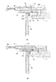
図3(b)に、図3(a)の構成における熱伝導経路を示す。図中、41は、ターゲット18から外側陽極部材12を介して収納容器1へ至る熱伝導経路であり、42は内側陽極部材13からの熱伝導経路である。内側陽極部材13は、外側陽極部材12よりも電子放出源31側に配置されており、電子放出部32で発生した熱を受けて温度が上昇するが、係る温度上昇は接触領域15から外側断熱部材12には伝わりにくい。よって、一部は接合材14を介して外側陽極部材12に伝わり、その他は絶縁管20を介して、或いは直接、絶縁性液体3に放熱される。よって、外側陽極部材12のターゲット18近傍には内側陽極部材13からの熱が伝わらず、ターゲット18で発生した熱は外側陽極部材12を介して速やかに収納容器1に放熱される。
FIG. 3B shows a heat conduction path in the configuration of FIG. In the figure, 41 is a heat conduction path from the
本発明においては、上記した熱伝導経路42を形成する上で、接合材14の位置は、図3(a)に示したように、内側陽極部材13の外周面が好ましい。よって、係る位置に接合材14を配置するべく、図3(a)に示すように、外側陽極部材12の管径方向の外周縁に絶縁管20側に突出する管状外周部12aを設け、内側陽極部材13の外周面と管状外周部12aの内周面とを接合することが好ましい。接合材14としては銀ろう等のろう材が好ましく用いられる。
In the present invention, in forming the
また、管径方向における接合材14の長さL1を接触領域15の長さL2よりも短くすることで、ターゲット18の温度上昇による外側陽極部材12の管径方向の伸びによって生じる接合材14に加わる応力集中を緩和することができる。これは、外側陽極部材12が管軸方向に撓み易い構成のためである。
Further, by making the length L1 of the
本発明において、外側陽極部材12は、ターゲット18で発生する熱を収納容器1へ放熱しやすい部材が好ましい。よって熱伝導率の高い材質が好ましく、例えば銅、タングステン、銅タングステンなどがよい。また、内側陽極部材13は、絶縁管20に接合されるため、絶縁管20と線膨張係数が近い素材が好ましく、絶縁管20がセラミックで構成された場合には、コバールが好ましく用いられる。
In the present invention, the
図4(a)は、内側陽極部材13と外側陽極部材12とを溶接で接合した例であり、図中の45が熱融着領域である。溶接で接合する場合には、図3(a)と同様に、外側陽極部材12の管径方向の外周縁に絶縁管側に突出する管状外周部12aを設け、内側陽極部材13の外周面と管状外周部12aの内周面とを接触させて、接触面において溶接により接合する。溶接方法としてはスポット溶接が好ましく用いられる。溶接によって内側陽極部材13と外側陽極部材12とが熱融着領域45を介して接合された場合、金属部材間の拡散範囲において伝熱的にも連続であり、内側陽極部材13と外側陽極部材12との間の熱抵抗が軽減されるため、好ましい形態である。
FIG. 4A is an example in which the
この時、内側陽極部材13と溶接によって接合される、管状外周部12aの内周側の領域12bを、内側陽極部材13と同じ素材とすることで、溶接がより容易になる。この場合、接合される領域12bは、ろう材等の接合材12cによって、隣接する領域と接合しておけばよい。
At this time, by making the inner
図4(a)の構成において、図4(b)に示すよう熱伝導経路41,42が形成され、ターゲット18で発生した熱は、電子放出部32からの放熱の影響を受けずに、外側陽極部材12を介して収納容器1に速やかに放熱される。
In the configuration of FIG. 4A,
尚、絶縁管20と接合される内側陽極部材13は、絶縁管20との接合領域が広くなるように、図3(a)、図4(a)に示すように、絶縁管20の外周面を囲んで陰極30側に突出する管状外周部13aを形成しても良い。
The
本発明に係る陰極30は、電子放出源31と、電子放出源31に接続された陰極部材34とを備え、絶縁管20の他端に接合材22を介して気密接合される。接合材21,22としては、銀ろう等のろう材が好ましく用いられる。陰極部材34は内側陽極部材13と同様に、絶縁管20と一体化されるため、絶縁管20がセラミックで構成される場合には、線膨張係数がセラミックに近い金属部材であるコバールが好ましく用いられる。
The
ターゲット18は透過型であり、X線を透過する透過基板と、該透過基板の内側(陰極30側)の片面に電子線の照射によりX線を放出するターゲット金属を含有するターゲット層を備えている。ターゲット18は、ターゲット層において電子照射を受け、ターゲット層が形成された透過基板の片面とは反対側の面からX線が放出される。ターゲット層は、高い原子番号、高融点、高比重の金属元素を、ターゲット金属として含有する。ターゲット金属は、原子番号42以上の金属元素から選択されるが、透過基板との親和性の観点からは、炭化物の標準生成自由エネルギーが負を呈するタンタル、モリブデン、タングステンの群から選択することがより好ましい。また、ターゲット金属は、ターゲット層に、単一組成又は合金組成の純金属として含有されていても良いし、当該金属の炭化物、窒化物、酸窒化物等の金属化合物として含有されていても良い。透過基板としては、例えばダイヤモンド、ベリリウムなどが好ましく用いられる。ターゲット18は、銀ろう等の不図示の接合材を介して外側陽極部材12に環状に気密接合されている。
The
電子放出源31は、電子放出部32がターゲット18に対向するように設けられている。電子放出源31としては、例えばタングステンフィラメント、含浸型カソードのような熱陰極や、カーボンナノチューブ等の冷陰極を用いることができる。電子放出源31は、電子線7のビーム径及び電子電流密度、オン・オフタイミング等の制御を目的として、不図示のグリッド電極、静電レンズ電極を備えることが可能である。本発明においては、特に、熱陰極を用いた場合に好適である。熱陰極を電子放出源31として用いた場合、電子線7の放出の有無にかかわらず、常に電子放出部32が発熱しており、従来のX線発生装置において、ターゲット18の放熱性に対する影響が大きいためである。尚、図2中の33は接続端子である。
The
上記構成の如く、絶縁管20と陽極部材11、絶縁管20と陰極部材34などをそれぞれ気密接合した構成により、X線発生管2内部の真空気密が維持された構成である。このような構成のX線発生管2の陰極30に適切な電圧設定を印加すると、電子放出部32から電子線7が放出される。電子線7はターゲット18に衝突し、X線8が放出され、収納容器1外へ放出される。
As described above, the inside of the
<X線撮影システム>
次に、図5を用いて、本発明のX線発生装置9を備えるX線撮影システムの構成例について説明する。本発明のX線撮影システムは、図2に示したX線発生装置9と、前記X線発生装置9から発生し、被検体56を透過したX線8を検出するX線検出装置53とシステム制御部51とを有する。システム制御部51は、X線発生装置9とX線検出装置53とを連携制御する。駆動回路6は、システム制御部51による制御の下に、X線発生管2に各種の制御信号を出力する。駆動回路6が出力する制御信号により、X線発生装置9から放出されるX線8の放出状態が制御される。X線発生装置9から放出されたX線8は、可動絞りを備えた不図示のコリメータユニットによりその照射範囲を調整されて、X線発生装置9の外部に放出され、被検体56を透過してX線検出器54で検出される。X線検出器54は、検出したX線を画像信号に変換して信号処理部55に出力する。信号処理部55は、システム制御部51による制御の下に、画像信号に所定の信号処理を施し、処理された画像信号をシステム制御部51に出力する。システム制御部51は、処理された画像信号に基づいて、表示装置52に画像を表示させるための表示信号を出力する。表示装置52は、表示信号に基づく画像を、被検体56の撮影画像としてスクリーンに表示する。
<X-ray imaging system>
Next, a configuration example of an X-ray imaging system including the X-ray generator 9 according to the present invention will be described with reference to FIG. The X-ray imaging system of the present invention includes the X-ray generator 9 shown in FIG. 2, the
本発明のX線撮影システムは、工業製品の非破壊検査や、人体や動物の病理診断に用いることができる。 The X-ray imaging system of the present invention can be used for nondestructive inspection of industrial products and pathological diagnosis of human bodies and animals.
1:収納容器、2:X線発生管、18:ターゲット、7:電子線、8:X線、9:X線発生装置、10:陽極、11:陽極部材、12:外側陽極部材、12a:管状外周部、13:内側陽極部材、14,21,22:接合材、18:ターゲット、20:絶縁管、30:陰極、31:電子放出源、45:熱融着領域、51:システム制御部、53:X線検出装置、56:被検体 1: storage container, 2: X-ray generator tube, 18: target, 7: electron beam, 8: X-ray, 9: X-ray generator, 10: anode, 11: anode member, 12: outer anode member, 12a: Tubular outer periphery, 13: inner anode member, 14, 21, 22: bonding material, 18: target, 20: insulating tube, 30: cathode, 31: electron emission source, 45: heat fusion region, 51: system controller 53: X-ray detection device, 56: Subject
Claims (21)
前記陽極部材は、前記ターゲットを保持し、前記収納容器に電気的に接続される外側陽極部材と、前記絶縁管の管軸方向において、前記外側陽極部材と前記電子放出源との間に位置し、前記絶縁管に接合される内側陽極部材と、を備え、
管径方向における前記絶縁管の外側において、前記内側陽極部材が前記外側陽極部材と伝熱的に接続されていることを特徴とするX線発生装置。 A transmission type target that generates X-rays upon electron irradiation, an anode having an anode member for holding the target, an electron emission source for irradiating the target with electrons, and a cathode having a cathode member connected to the electron emission source If, before Symbol X-ray generation tube having an insulating tube which is airtightly joined respectively to the disposed the anode member and the cathode member between the anode member and the cathode member, and are connected to said anode member An X-ray generation apparatus comprising a conductive storage container for storing the X-ray generation tube,
The anode member is positioned between the outer anode member that holds the target and is electrically connected to the storage container, and the outer anode member and the electron emission source in the tube axis direction of the insulating tube. And an inner anode member joined to the insulating tube,
An X-ray generator, wherein the inner anode member is connected to the outer anode member in a heat transfer manner outside the insulating tube in a tube diameter direction.
前記陽極部材は、前記ターゲットから前記収納容器に熱を伝導する外側陽極部材と、前記電子放出源から前記絶縁性液体に熱を伝導する内側陽極部材と、を有することを特徴とするX線発生装置。The anode member includes an outer anode member that conducts heat from the target to the receiving container, and an inner anode member that conducts heat from the electron emission source to the insulating liquid. apparatus.
前記管軸方向において、前記内側陽極部材の表面と前記外側陽極部材の表面とが互いに接触していることを特徴とする請求項11に記載のX線発生装置。 The outer anode member has a tubular outer peripheral portion protruding from the outer peripheral edge in the tube diameter direction toward the insulating tube, and the inner peripheral surface of the tubular outer peripheral portion and the outer peripheral surface of the inner anode member serve as the bonding material. Are joined to each other through
The X-ray generator according to claim 11 , wherein a surface of the inner anode member and a surface of the outer anode member are in contact with each other in the tube axis direction.
前記管状外周部の内周面と前記内側陽極部材の外周面、及び前記管軸方向における前記内側陽極部材の表面と前記外側陽極部材の表面とがそれぞれ互いに接触する接触面を有しており、
前記管状外周部の内周面と前記内側陽極部材の外周面とが、前記接触面において、前記熱融着領域を介して接合されていることを特徴とする請求項14に記載のX線発生装置。 The outer anode member has a tubular outer peripheral portion protruding from the outer peripheral edge in the tube diameter direction toward the insulating tube;
The inner peripheral surface of the tubular outer peripheral portion and the outer peripheral surface of the inner anode member, and the surface of the inner anode member and the surface of the outer anode member in the tube axis direction have contact surfaces that contact each other,
The X-ray generation according to claim 14 , wherein an inner peripheral surface of the tubular outer peripheral portion and an outer peripheral surface of the inner anode member are joined to each other at the contact surface via the heat fusion region. apparatus.
Priority Applications (3)
| Application Number | Priority Date | Filing Date | Title |
|---|---|---|---|
| JP2014229592A JP6388400B2 (en) | 2014-11-12 | 2014-11-12 | X-ray generator and X-ray imaging system using the same |
| US14/882,607 US9741524B2 (en) | 2014-11-12 | 2015-10-14 | X-ray generating apparatus and radiography system using the same |
| US15/644,003 US9831060B2 (en) | 2014-11-12 | 2017-07-07 | X-ray generating apparatus and radiography system using the same |
Applications Claiming Priority (1)
| Application Number | Priority Date | Filing Date | Title |
|---|---|---|---|
| JP2014229592A JP6388400B2 (en) | 2014-11-12 | 2014-11-12 | X-ray generator and X-ray imaging system using the same |
Publications (3)
| Publication Number | Publication Date |
|---|---|
| JP2016095916A JP2016095916A (en) | 2016-05-26 |
| JP2016095916A5 JP2016095916A5 (en) | 2017-12-14 |
| JP6388400B2 true JP6388400B2 (en) | 2018-09-12 |
Family
ID=55912785
Family Applications (1)
| Application Number | Title | Priority Date | Filing Date |
|---|---|---|---|
| JP2014229592A Active JP6388400B2 (en) | 2014-11-12 | 2014-11-12 | X-ray generator and X-ray imaging system using the same |
Country Status (2)
| Country | Link |
|---|---|
| US (2) | US9741524B2 (en) |
| JP (1) | JP6388400B2 (en) |
Families Citing this family (7)
| Publication number | Priority date | Publication date | Assignee | Title |
|---|---|---|---|---|
| JP6611490B2 (en) * | 2015-07-02 | 2019-11-27 | キヤノン株式会社 | X-ray generator and X-ray imaging system using the same |
| JP6573380B2 (en) * | 2015-07-27 | 2019-09-11 | キヤノン株式会社 | X-ray generator and X-ray imaging system |
| JP6525941B2 (en) * | 2016-10-28 | 2019-06-05 | キヤノン株式会社 | X-ray generator and X-ray imaging system |
| WO2018092174A1 (en) | 2016-11-17 | 2018-05-24 | キヤノンアネルバ株式会社 | X-ray generator and radiography system |
| US10624195B2 (en) * | 2017-10-26 | 2020-04-14 | Moxtek, Inc. | Tri-axis x-ray tube |
| WO2020213039A1 (en) * | 2019-04-15 | 2020-10-22 | キヤノンアネルバ株式会社 | X-ray generation device and x-ray imaging device |
| US20230243762A1 (en) * | 2022-01-28 | 2023-08-03 | National Technology & Engineering Solutions Of Sandia, Llc | Multi-material patterned anode systems |
Family Cites Families (5)
| Publication number | Priority date | Publication date | Assignee | Title |
|---|---|---|---|---|
| JPS546882U (en) * | 1977-06-17 | 1979-01-17 | ||
| EP0553912B1 (en) * | 1992-01-27 | 1998-01-07 | Koninklijke Philips Electronics N.V. | X-ray tube with improved temperature control |
| JP2004235113A (en) * | 2003-01-31 | 2004-08-19 | Tadahiro Omi | Softer x ray generation tube |
| JP5179797B2 (en) | 2007-08-10 | 2013-04-10 | 浜松ホトニクス株式会社 | X-ray generator |
| JP6264145B2 (en) * | 2014-03-28 | 2018-01-24 | 株式会社島津製作所 | X-ray generator |
-
2014
- 2014-11-12 JP JP2014229592A patent/JP6388400B2/en active Active
-
2015
- 2015-10-14 US US14/882,607 patent/US9741524B2/en active Active
-
2017
- 2017-07-07 US US15/644,003 patent/US9831060B2/en active Active
Also Published As
| Publication number | Publication date |
|---|---|
| US20160133429A1 (en) | 2016-05-12 |
| US20170316911A1 (en) | 2017-11-02 |
| US9831060B2 (en) | 2017-11-28 |
| US9741524B2 (en) | 2017-08-22 |
| JP2016095916A (en) | 2016-05-26 |
Similar Documents
| Publication | Publication Date | Title |
|---|---|---|
| JP6388400B2 (en) | X-ray generator and X-ray imaging system using the same | |
| JP6039282B2 (en) | Radiation generator and radiation imaging apparatus | |
| JP6039283B2 (en) | Radiation generator and radiation imaging apparatus | |
| US9401259B2 (en) | Radiation generating tube, and radiation generating apparatus and radiation imaging system using the same | |
| US9373478B2 (en) | Radiation generating apparatus and radiation imaging apparatus | |
| JP6552289B2 (en) | X-ray generator tube, X-ray generator, X-ray imaging system | |
| JP2016085945A5 (en) | ||
| US10062539B2 (en) | Anode and x-ray generating tube, x-ray generating apparatus, and radiography system that use the anode | |
| JP2016095916A5 (en) | ||
| WO2006009053A1 (en) | Fixed anode x-ray tube, x-ray inspection device using the same, and x-ray irradiation device | |
| JP6611490B2 (en) | X-ray generator and X-ray imaging system using the same | |
| JP6153314B2 (en) | X-ray transmission type target and manufacturing method thereof | |
| JP6659167B2 (en) | X-ray generating tube equipped with electron gun and X-ray imaging apparatus | |
| JP2002042705A (en) | Transmissive radiation type x-ray tube and manufacturing method thereof | |
| JP2015114132A (en) | Radiation tube and radiation inspection device | |
| JP2015076213A (en) | Radiation tube, radiation generating device and radiographic system | |
| JP2005228696A (en) | Fixed anode x-ray tube | |
| JP2015060731A (en) | Radiation generating tube and radiation generator using the same, radiographic system | |
| JP2015005337A (en) | Radiation generation target, radiation generation tube using the same, radiation generation device, and radiation imaging system | |
| JP2015076214A (en) | Radiation tube and radiation inspection device | |
| JP5725827B2 (en) | Radiation generator and radiation imaging system | |
| JP6580231B2 (en) | X-ray generator tube, X-ray generator and X-ray imaging system | |
| JP6611495B2 (en) | X-ray generator tube, X-ray generator and X-ray imaging system | |
| JP5449118B2 (en) | Transmission type radiation tube, radiation generator, and radiation imaging apparatus | |
| JP2016085946A (en) | X-ray generation tube, x-ray generator and radiography system |
Legal Events
| Date | Code | Title | Description |
|---|---|---|---|
| A521 | Request for written amendment filed |
Free format text: JAPANESE INTERMEDIATE CODE: A523 Effective date: 20171031 |
|
| A621 | Written request for application examination |
Free format text: JAPANESE INTERMEDIATE CODE: A621 Effective date: 20171031 |
|
| TRDD | Decision of grant or rejection written | ||
| A01 | Written decision to grant a patent or to grant a registration (utility model) |
Free format text: JAPANESE INTERMEDIATE CODE: A01 Effective date: 20180717 |
|
| A61 | First payment of annual fees (during grant procedure) |
Free format text: JAPANESE INTERMEDIATE CODE: A61 Effective date: 20180810 |
|
| R151 | Written notification of patent or utility model registration |
Ref document number: 6388400 Country of ref document: JP Free format text: JAPANESE INTERMEDIATE CODE: R151 |