JP6153314B2 - X-ray transmission type target and manufacturing method thereof - Google Patents
X-ray transmission type target and manufacturing method thereof Download PDFInfo
- Publication number
- JP6153314B2 JP6153314B2 JP2012252989A JP2012252989A JP6153314B2 JP 6153314 B2 JP6153314 B2 JP 6153314B2 JP 2012252989 A JP2012252989 A JP 2012252989A JP 2012252989 A JP2012252989 A JP 2012252989A JP 6153314 B2 JP6153314 B2 JP 6153314B2
- Authority
- JP
- Japan
- Prior art keywords
- target
- ray
- radiation
- heat dissipation
- diamond substrate
- Prior art date
- Legal status (The legal status is an assumption and is not a legal conclusion. Google has not performed a legal analysis and makes no representation as to the accuracy of the status listed.)
- Active
Links
Images


Description
本発明は、医療機器分野における診断応用や産業機器分野における非破壊X線撮影等に適用できる放射線透過型ターゲット、放射線発生管、放射線発生装置及び放射線撮影システムに関する。 The present invention relates to a radiation transmission target, a radiation generating tube, a radiation generating apparatus, and a radiation imaging system that can be applied to diagnostic applications in the medical equipment field and non-destructive X-ray imaging in the industrial equipment field.
放射線発生管は電子放出源から放出される電子を高電圧で加速し、タングステン等の金属で構成されるターゲットに照射してX線等の放射線を発生させる。 The radiation generating tube accelerates electrons emitted from the electron emission source with a high voltage and irradiates a target made of a metal such as tungsten to generate radiation such as X-rays.
X線撮影に好適な放射線を発生させるためには、電子放出源とターゲット間に40kV〜150kVの高電圧を印加して、管電流と呼ぶ加速した電子流としての高エネルギーの電子線をターゲットに照射する必要がある。しかし、一般的に放射線の発生効率は極めて悪く、消費電力の99%程度はターゲットにおいて熱となる。この発生した熱によりターゲットは高温になるため、ターゲットの熱損傷を防ぐ手段が必要となる。 In order to generate radiation suitable for X-ray photography, a high voltage of 40 kV to 150 kV is applied between the electron emission source and the target, and a high energy electron beam as an accelerated electron flow called tube current is used as the target. Irradiation is necessary. However, in general, the radiation generation efficiency is extremely poor, and about 99% of the power consumption becomes heat in the target. Since the target is heated by the generated heat, a means for preventing thermal damage of the target is required.
ターゲットの熱損傷を防ぐ手段として、特許文献1には、電子ビームが照射されるターゲットの表面又は裏面に接する様に熱伝導性が良い放熱層を備えているX線発生管が提案されている。
As a means for preventing thermal damage of the target,
また、特許文献2には、ターゲット支持基板の表面に輻射による放熱層として二酸化チタンを含有する酸化物を形成する際に、放熱層の劣化防止のため中間層を導入することが提案されている。そして、この中間層、放熱層共にターゲット支持基板とは異種材料を使用している。
しかし、何れの特許文献においても、基板と異種材料を放熱層に使用しているため、局所的な温度上昇による熱膨張係数の違いに起因して放熱層が剥れる場合があった。 However, in any of the patent documents, since a different material from the substrate is used for the heat dissipation layer, the heat dissipation layer may be peeled off due to a difference in thermal expansion coefficient due to a local temperature rise.
また、透過型X線管においては、ターゲット支持基板のターゲット反対側に放熱層を形成する際に特許文献2にある様に酸化物放熱層を用いると、X線が急激に減衰してしまう課題があった。
Further, in the transmission type X-ray tube, when an oxide heat dissipation layer is used as disclosed in
特に、X発生管を備えるX線撮影装置に関しては、撮影画質の向上が望まれており、医療分野においては診断精度を高める為に輪郭解像度を上げる必要がある。解像度向上が必要な場合としては、例えば循環器等の動きや患者の体の動きに対応して短時間での撮影となる場合があり、短パルス・大管電流が必要となる。また、産業分野ではデバイスの高集積化に伴い、検査時の透過像も高解像度の画質が望まれる。そのためには、例えばターゲットに入射する電子線の焦点を絞った撮影が要求される場合があり、局所的な電流密度が高くなる。 In particular, with respect to an X-ray imaging apparatus including an X generator tube, improvement in imaging image quality is desired, and in the medical field, it is necessary to increase the contour resolution in order to increase diagnostic accuracy. When the resolution needs to be improved, for example, imaging may be performed in a short time corresponding to the movement of the circulatory organ or the like or the movement of the patient's body, and a short pulse and a large tube current are required. Further, in the industrial field, with the high integration of devices, a high-resolution image quality is desired for a transmission image at the time of inspection. For this purpose, for example, photographing with a focused electron beam incident on the target may be required, and the local current density becomes high.
一方、X線撮影装置は医療分野では可搬性、取扱容易性から小型軽量化のニーズもあり、放熱用の絶縁油を重量の軽い絶縁性気体に変更する場合もある。 On the other hand, in the medical field, there is a need to reduce the size and weight of the X-ray imaging apparatus because of its portability and ease of handling, and the insulating oil for heat radiation may be changed to a light insulating gas.
X線撮影装置の使用に際し、医療分野での短時間パルス・大管電流撮影に伴いターゲットに対して瞬間的な温度上昇が発生し、又、産業分野においての高解像度撮影は電子線の焦点を絞る為、ターゲットの局所的な温度負荷の上昇が発生する。さらに小型、軽量化の為に放熱用の絶縁油を重量の軽い絶縁性気体に変更した場合は熱伝導による放熱能力が低下する。そのため、温度上昇によりターゲットに溶融等の熱損傷が発生することがあり、改良が望まれている。 When using X-ray imaging equipment, instantaneous temperature rise occurs with the target due to short-time pulse and large tube current imaging in the medical field, and high-resolution imaging in the industrial field focuses the electron beam. As a result, the local temperature load of the target increases. Furthermore, if the insulating oil for heat dissipation is changed to a light insulating gas for the purpose of miniaturization and weight reduction, the heat dissipation capability due to heat conduction decreases. Therefore, thermal damage such as melting may occur in the target due to temperature rise, and improvement is desired.
そこで、本発明はターゲット支持基板の冷却を可能とする放射線透過型ターゲット、これを用いた放射線発生管及び放射線発生装置、並びに放射線発生装置を備え、撮影時に高解像度の画質を得ることができる放射線撮影システムを提供することを目的とする。 Therefore, the present invention includes a radiation transmissive target capable of cooling the target support substrate, a radiation generating tube and a radiation generating apparatus using the target, and a radiation generating apparatus, and radiation capable of obtaining high-resolution image quality at the time of imaging. An object is to provide a photographing system.
即ち、本発明のX線透過型ターゲットは、ダイヤモンド基板と、前記ダイヤモンド基板の一方の面に配置された、ターゲット金属を含有するターゲット層と、を有するX線透過型ターゲットであって、前記ダイヤモンド基板の前記ターゲット層が設けられた面とは反対側の面に、炭素を含有し前記ダイヤモンド基板より高い輻射率(放射率)を呈する放熱層を有することを特徴とする。
また、本発明のX線透過型ターゲットの製造方法は、ダイヤモンド基板の一方の面に、ターゲット金属を含有するターゲット層を形成する工程と、
前記ダイヤモンド基板の前記ターゲット層が形成される面とは反対側の面に、気相成長法または前記ダイヤモンド基板の加熱により、炭素を含有し前記ダイヤモンド基板より高い輻射率を呈する放熱層を形成する工程と、を有することを特徴とする。
また、本発明のX線透過型ターゲットの製造方法は、ダイヤモンド基板の一方の面に、ターゲット金属を含有するターゲット層を形成する工程と、
前記ダイヤモンド基板の前記ターゲット層が形成される面とは反対側の面に、前記ダイヤモンド基板の結晶構造を変化させて、炭素を含有し前記ダイヤモンド基板より高い輻射率を呈する放熱層を形成する工程と、を有することを特徴とする。
Ie, X-ray transmission type target of the present invention, a diamond board, wherein arranged on one surface of the diamond substrate, an X-ray transmission type target having a target layer containing a target metal, a, A heat dissipation layer containing carbon and exhibiting a higher emissivity (emissivity) than the diamond substrate is provided on a surface of the diamond substrate opposite to the surface on which the target layer is provided .
Moreover, the manufacturing method of the X-ray transmissive target of the present invention includes a step of forming a target layer containing a target metal on one surface of a diamond substrate,
A heat dissipation layer containing carbon and exhibiting a higher emissivity than the diamond substrate is formed on the surface of the diamond substrate opposite to the surface on which the target layer is formed, by vapor deposition or heating of the diamond substrate. And a process.
Moreover, the manufacturing method of the X-ray transmissive target of the present invention includes a step of forming a target layer containing a target metal on one surface of a diamond substrate,
A step of changing the crystal structure of the diamond substrate on a surface opposite to the surface on which the target layer is formed of the diamond substrate to form a heat dissipation layer containing carbon and exhibiting a higher emissivity than the diamond substrate. It is characterized by having.
本発明によれば、ターゲットの局所的な温度上昇が発生する動作においても、放熱層の膜剥れが発生せず、かつX線の減衰も小さく、放熱層による輻射率向上で基板温度の局所的な上昇を抑えることが出来、ターゲットへの熱損傷が軽減できる。 According to the present invention, even in an operation in which a local temperature rise of the target occurs, the heat radiation layer does not peel off, the X-ray attenuation is small, and the radiation temperature is improved by the heat radiation layer, thereby increasing the local temperature of the substrate. Rise can be suppressed and thermal damage to the target can be reduced.
以下、図面を参照して本発明の放射線透過型ターゲット及びこれを用いた放射線発生管、放射線発生装置及び放射線撮影システムの好適な実施形態を、主に、放射線がX線である場合を例にとり説明するが、本発明はこれらの実施形態に限定されない。 Hereinafter, preferred embodiments of a radiation transmission target of the present invention and a radiation generating tube, a radiation generating apparatus, and a radiation imaging system using the same will be described with reference to the drawings, mainly taking the case where the radiation is X-rays as an example. Although described, the present invention is not limited to these embodiments.
<第1の実施形態>
図1(a)は本発明の放射線透過型ターゲットを用いた放射線発生管の一実施形態を示す断面模式図であり、図1(b)は図1(a)における放射線透過型ターゲット部を拡大した断面模式図である。
<First Embodiment>
FIG. 1A is a schematic cross-sectional view showing an embodiment of a radiation generating tube using the radiation transmissive target of the present invention, and FIG. 1B is an enlarged view of the radiation transmissive target portion in FIG. FIG.
本発明の放射線発生管10は透過型のX線発生管である。本発明の放射線発生管10は、本発明の放射線透過型ターゲット20として、ターゲット金属14、支持基板15及び放熱層16からなるX線透過型ターゲット、外囲器18、電子線発生手段21、放射線遮蔽部材17としてX線遮蔽部材を備えている。
The
放射線発生管10には、図1に示すように排気管9を設けても良い。排気管9を設けた場合は、排気管9を通じて外囲器18内を真空に排気した後に排気管9を封止することで外囲器18の内部を真空にすることができる。
The
外囲器18は、放射線発生管10の内部を真空に保つためのもので、セラミックス材料やガラス等が用いられる。外囲器18内の真空度は10-4Pa〜10-8Pa程度であれば良く、外囲器18の内部には真空度を向上するために、ゲッター(不図示)を配置しても良い。また、外囲器18は、開口部を有しており、その開口部に、ターゲット20、放射線遮蔽部材17が接合されることにより外囲器18が密閉される。
The
電子線発生手段21は、電子放出源11を備えている。電子放出源11は、外囲器18の内部に、ターゲット金属14に対向して配置されている。電子放出源11にはタングステンフィラメントや、含浸型カソードのような熱陰極、又はカーボンナノチューブ等の冷陰極を用いることができる。電子線発生手段21には、図1に示すように引出し電極12とレンズ電極13を設けても良い。これらを電子放出源11の近傍に設けた場合、引出し電極12によって形成される電界によって放出された電子は、レンズ電極13で収束され、ターゲット金属14に入射しターゲット金属14からX線が発生し、透過窓19より出射される。このとき、電子放出源11とターゲット金属14の間に印加される電圧Vaは、X線の使用用途によって異なるものの、概ね40kV〜120kV程度である。
The electron beam generating means 21 includes an
本発明の放射線透過型ターゲット及びその周辺の詳細構造を図1(b)で説明する。 The detailed structure of the radiation transmission target of the present invention and its periphery will be described with reference to FIG.
本発明の放射線透過型ターゲットは、支持基板15上にターゲット金属14を有し、支持基板15のターゲット金属14を有する面とは反対側の面に放熱層16を有する。
The radiation transmissive target of the present invention has a
ターゲット金属14は、支持基板15の片面(電子放出源側の面)に配置されている。ターゲット金属14を構成する材料は、融点が高く、放射線発生効率の高いものが好ましい。例えばタングステン、タンタル、モリブデン等を用いることができる。発生したX線がターゲット金属14を透過する際に生じる吸収を軽減するため、ターゲット金属14の厚みは数μm〜十数μm程度が適当である。
The
支持基板15を構成する材料は、ターゲット金属14を支持できる強度を有し、ターゲット金属14で発生したX線の吸収が少なく、かつターゲット金属14で発生した熱をすばやく放熱できるよう熱伝導率の高いものが好ましい。例えばダイヤモンド、炭化シリコン、窒化アルミニウム等を用いることができる。上記要求事項を満たすためには、支持基板15の厚みは0.1mm〜数mm程度が適当である。
The material constituting the
放熱層16は、ターゲット金属14を有する面と反対側の面に形成されている。放熱層16の厚さは数μmあれば良い。そして、放熱層は、支持基板15に含まれる元素と同一元素を含み、輻射率が支持基板15より大きく、かつ軽元素からなる。
The
局所的な発熱により支持基板15と放熱層16の密着力が不十分な場合、熱応力により放熱層16が剥れてしまうことがあるが、本発明では基板に含まれる元素と同一元素を含む放熱層16を形成することで密着力を向上することが可能となる。
When the adhesive force between the
また、支持基板15の輻射率は、例えば炭化シリコン基板で0.5以下、ダイヤモンドの場合は表面研磨した基板で0.2以下と小さい。その為、本発明では、輻射率が支持基板15より大きい放熱層16を形成し、支持基板15表面からの放熱を促進する。例えば、支持基板15が炭化シリコンの場合は、放熱層16としてカーボンを含む輻射率の高いダイヤモンドライクカーボンを形成する。また、支持基板15がダイヤモンドの場合においては、例えば輻射率が0.90と高いグラファイトを放熱層16として形成する。
The emissivity of the
また、本発明では、軽元素からなる放熱層16を形成するため、放熱層16での放射線の減衰は小さい。例えば、ダイヤモンドライクカーボン、グラファイト共に、軽元素である炭素より形成されるのでX線の減衰は小さい。
In the present invention, since the
放熱層16の形成方法は特に限定されないが、例えばプラズマCVD法やスパッタリング法などの気相成長法にて形成できる。また、支持基板15がダイヤモンドの場合は表面の結晶構造を変化させて形成してもよい。ダイヤモンドは炭素原子が共有結合からなる面心立方結晶から形成されているが、グラファイトは炭素原子が層状の六角板状結晶から形成されている。ダイヤモンドに熱を加えることで結晶構造が変化してグラファイト化がおこり、輻射率も変化する。
The method for forming the
ターゲット20の支持基板15は、放射線遮蔽部材17に対して固定され、外囲器18の真空気密が維持されるが、この固定手段としては銀ろう付けが好適に用いられる。
The
また、ターゲット20外周側には、支持基板15を囲んで放射線遮蔽部材17が設けられている。放射線遮蔽部材17の外囲器18への取り付け方法としては、ろう付け、鋳こみ、ハンダ付け、溶接、レーザー溶接、ネジこみ、焼きバメ、テーパーはめ込み、接着剤による接合、機械的なネジ止め等が挙げられる。
A
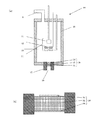
次に、本発明の放射線発生管を備える放射線発生ユニットについて説明する。図2は図1の放射線発生管を備える放射線発生ユニットの構成の一例を示す断面模式図である。 Next, a radiation generating unit including the radiation generating tube of the present invention will be described. FIG. 2 is a schematic cross-sectional view showing an example of the configuration of a radiation generating unit including the radiation generating tube of FIG.
図2の放射線発生ユニット30は、透過型のX線発生管である放射発生管10を備えており、この放射線発生管10は収納容器1の内部に収容されている。この収納容器1内に放射線発生管10を収容した余空間には絶縁性流体8が充填されている。収納容器1の内部には、図2に示すように不図示の回路基板及び絶縁トランス等から構成される駆動回路3を設けても良い。駆動回路3を設けた場合、例えば放射線発生管10に端子4、5、6、7を介して駆動回路3から電圧信号が印加されX線の発生を制御することができる。
The
収納容器1は、容器としての十分な強度を有していれば良く、金属やプラスチックス材料等から構成される。収納容器1には、X線を透過し収納容器1の外部にX線を取り出すための放出窓2が設けられている。放射線発生管10から放出されたX線はこの放出窓2を通して外部に放出される。放出窓2には、ガラス、アルミニウム、ベリリウム等が用いられる。
The
絶縁性流体8は、電気絶縁性を有していれば良く、液体でも気体でも良い。例えば絶縁媒体及び放射線発生管10の冷却効果を重視すれば、冷却媒体としての役割を有する電気絶縁油を用いるのが好ましい。電気絶縁油としては、鉱油、シリコーン油、フッ素系電気絶縁性液体等が好適に用いられる。一方、軽量、小型化を重視するならば、気体を用いた方が絶縁性液体よりも装置を軽くすることができる。気体では空気や六フッ化硫黄等が用いられ、六フッ化硫黄がより好適に用いられる。本発明では、絶縁性流体8に気体を使用し熱伝達率が小さくなった場合においても、輻射にて有効に収納容器1へ放熱する。
The insulating
<第2の実施形態>
図3は本発明の放射線透過型ターゲットを用いた放射線発生管の他の例を示す断面模式図である。
<Second Embodiment>
FIG. 3 is a schematic cross-sectional view showing another example of a radiation generating tube using the radiation transmissive target of the present invention.
本例の放射線発生管は透過型の回転陽極を有する。具体的には、図3に示す様に、本発明の放射線透過型ターゲット20の支持基板15を、回転機構のローター43へつながる円盤状のキャリア42に接着して、円周状にターゲット20を配置する。
The radiation generating tube of this example has a transmission type rotating anode. Specifically, as shown in FIG. 3, the
引出し電極12によって形成される電界によって、電子放出源11より放出された電子線40は、レンズ電極13で収束され、ターゲット金属14に入射しターゲット金属14から放射線41が発生し、支持基板15を透過して透過窓19より出射される。
The
本実施形態においても、第1の実施形態と同様にターゲット20の熱損傷を軽減できる。更に、本実施形態の利点は、放射線発生時にはキャリア42が回転してターゲット20が移動して、異なった位置に電子線40が照射される為、ターゲット金属14及び支持基板15の温度上昇が抑制される。これより大きな電子線量を注入でき、発生する放射線強度を大きくすることができる。さらに、円周状にターゲット20を複数配置していることから、それに対応して放熱層16も面積が大きくなる。よって、電子線40が照射されていないターゲット20の放熱層16からも放熱され放熱効率が向上する。
Also in this embodiment, the thermal damage of the
<第3の実施形態>
図4に基づいて、本発明に係る放射線撮影システムの一例を説明する。
<Third Embodiment>
An example of a radiation imaging system according to the present invention will be described based on FIG.
本例において、既に説明した放射線発生ユニット30は、その放出窓2部分に設けられた可動絞りユニット100と共に放射線発生装置200を構成している。可動絞りユニット100は、放射線発生ユニット30から照射される放射線の照射野の広さを調整する機能を有する。また、可動絞りユニット100として、放射線の照射野を可視光により模擬表示できる機能が付加されたものを用いることもできる。
In this example, the
システム制御装置202は、放射線発生装置200と放射線検出装置201とを連携制御する。駆動回路3は、システム制御装置202による制御の下に、放射線発生管10に各種の制御信号を出力する。この制御信号により、放射線発生装置200から放出される放射線の放出状態が制御される。放射線発生装置200から放出された放射線は、被検体204を透過して検出器206で検出される。検出器206は、検出した放射線を画像信号に変換して信号処理部205に出力する。信号処理部205は、システム制御装置202による制御の下に、画像信号に所定の信号処理を施し、処理された画像信号をシステム制御装置202に出力する。システム制御装置202は、処理された画像信号に基づいて、表示装置203に画像を表示させるための表示信号を表示装置203に出力する。表示装置203は、表示信号に基づく画像を、被検体204の撮影画像としてスクリーンに表示する。放射線の代表例はX線であり、本発明の放射線発生ユニット30と放射線撮影システムは、X線発生ユニットとX線撮影システムとして利用することができる。X線撮影システムは、工業製品の非破壊検査や人体や動物の病理診断に用いることができる。
The
<実施例1>
図1に示す放射線発生管としてX線発生管を用いて、図2に示す放射線発生ユニットを作製した。
<Example 1>
A radiation generating unit shown in FIG. 2 was produced using an X-ray generating tube as the radiation generating tube shown in FIG.
支持基板15としての直径10mm厚さ1mmのダイヤモンドの表面に、ターゲット金属14としてタングステンを1μmの厚さにてスパッタ成膜した。その後、支持基板15のターゲット金属14を有する面とは反対側の面を真空雰囲気中にて1500℃に加熱し、約1μm程度の深さでグラファイト化して放熱層16を形成した。X線を遮蔽する放射線遮蔽部材17に接着する箇所等の放熱層16が不要な箇所をエッチングにより除去して、X線を透過するターゲット20を得た。
On the surface of diamond having a diameter of 10 mm and a thickness of 1 mm as the
支持基板15と放熱層16の密着力が不十分な場合には、使用時の局所的な発熱により放熱層16が剥れてしまうことがある。しかし、本実施例では、支持基板15であるダイヤモンドに含まれる元素と同一元素である炭素を含むグラファイトの放熱層を形成しており、更には支持基板15の一部を変性して放熱層16を形成している為、基板への密着力が向上する。
If the adhesion between the
また、ダイヤモンド基板の輻射率は0.2程度であるが、表面のグラファイトの輻射率は0.90となり、裏面からの輻射による放熱効率が向上した。また、放熱層16は軽元素である炭素より形成されるのでX線の減衰は小さい。
Further, the radiation rate of the diamond substrate was about 0.2, but the radiation rate of the graphite on the surface was 0.90, and the heat radiation efficiency by radiation from the back surface was improved. Further, since the
得られたターゲット20を放射線遮蔽部材17にろう付けで固定し、溶接にて外囲器18へ接合し、図1に示す放射線発生管10を作製した。
The obtained
この放射線発生管10を用いて、図2に示す放射線発生ユニットを作製した。収納容器1はSUSから構成され、X線を透過するベリリウムの放出窓2が設けられている。収納容器1内に充填させる絶縁性流体8としては、耐電圧確保及び省スペース、軽量化の為、六フッ化硫黄を用いた。
A radiation generating unit shown in FIG. 2 was produced using this
タングステンフィラメントからなる電子放出源11を、不図示の加熱手段によって加熱し、電子を放出させた。また、放出された電子を、引出し電極12、レンズ電極13に印加した電圧によって生じる電位分布によって放出された電子の電子線軌道を制御した。
The
更に、放出された電子を、電子放出源11とターゲット金属14間に印加される電圧Vaによって高エネルギーに加速することでターゲット金属14に衝突させ、X線を発生させた。
Further, the emitted electrons were accelerated to high energy by the voltage Va applied between the
この際に支持基板15の熱は主に放射線遮蔽部材17から外囲器18へと伝導していき放熱する。一方、放熱層16からの輻射エネルギーは1.4(W)となり、放熱層16が無い支持基板15と比較して4.5倍の放熱を行っている。これにより支持基板15の裏面温度は500℃となった。また、輻射エネルギーが7.6(W)の際の裏面温度は900℃となった。
At this time, heat of the
本実施例によれば、支持基板15の裏面の放熱層16全体より放熱されることから、支持基板15の局所的な温度上昇を抑えることが出来、ターゲット20への熱損傷が軽減できた。
According to the present embodiment, since heat is radiated from the entire
<実施例2(参考例)>
支持基板15としての1mmの炭化シリコンの表面に、ターゲット金属14としてタングステンを1μm厚さにてスパッタ成膜した。その後、支持基板15のターゲット金属14を有する面とは反対側の面に、放熱層16として厚さ1μmのダイヤモンドライクカーボンをプラズマCVD法にて形成し、X線を透過するターゲット20を得た。
<Example 2 (reference example) >
On the surface of 1 mm silicon carbide as the
本実施例では、支持基板15である炭化シリコンに含まれる元素と同一元素である炭素を含むダイヤモンドライクカーボンの放熱層16を形成することで、支持基板15と放熱層16の密着力が向上する。また、研磨された炭化シリコン基板の輻射率は0.5であるが、ダイヤモンドライクカーボンの輻射率は0.80となり、輻射による放熱量が増加して有効に放熱される。また、放熱層16は軽元素である炭素より形成されるのでX線の減衰は小さい。
In this embodiment, the adhesion force between the
得られたターゲット20を用いた以外は実施例1と同様にして、放射線発生管及び放射線発生ユニットを作製した。
A radiation generating tube and a radiation generating unit were produced in the same manner as in Example 1 except that the obtained
本実施例においても、実施例1と同様にターゲット20への熱損傷が軽減できた。
Also in the present embodiment, the thermal damage to the
<実施例3>
図3に示す放射線発生管としてX線発生管を用い、放射線発生ユニットを作製した。
<Example 3>
A radiation generating unit was prepared using an X-ray generating tube as the radiation generating tube shown in FIG.
支持基板15としての直径10mm厚さ2mmのダイヤモンドの表面に、ターゲット金属14としてタングステンを1μmの厚さにてスパッタ成膜した。その後、支持基板15のターゲット金属14を有する面とは反対側の面に、放熱層16として厚さ1μmのダイヤモンドライクカーボンをプラズマCVD法にて形成した。キャリア42に接着する箇所等の放熱層16が不要な箇所はエッチングにより除去して、X線を透過するターゲット20を得た。
On the surface of diamond having a diameter of 10 mm and a thickness of 2 mm as the
このターゲット20の支持基板15を回転機構のローター43へつながる円盤状のキャリア42に接着して、複数のターゲット20を円周状に配置した以外は、実施例1と同様にして、放射線発生管及び放射線発生ユニットを作製した。
The radiation generating tube is the same as in Example 1 except that the
本実施例では、支持基板15であるダイヤモンドに含まれる元素と同一元素である炭素を含むダイヤモンドライクカーボンの放熱層16を形成することで、支持基板15と放熱層16の密着力が向上する。また、ダイヤモンド基板の輻射率は0.2程度であるが、ダイヤモンドライクカーボンの輻射率は0.80となり、輻射による放熱量が増加して有効に放熱される。また、放熱層16は軽元素である炭素より形成されるのでX線の減衰は小さい。
In this embodiment, the adhesion force between the
さらに、本実施例では円周状にターゲット20を複数配置していることから、それに対応して放熱層16も面積が大きくなる。よって電子線40が照射されていないターゲット20の放熱層16からも放熱され放熱効率が向上する。
Further, in the present embodiment, since a plurality of
以上の構成において、支持基板15の熱は裏面の放熱層16全体より放熱されることから、実施例1と同様にターゲットへの熱損傷が軽減できた。
In the above configuration, the heat of the
1:収納容器、2:放出窓、3:駆動回路、4,5,6,7:端子、8:絶縁性流体、9:排気管、10:放射線発生管、11:電子放出源、12:引出し電極、13:レンズ電極、14:ターゲット金属、15:支持基板、16:放熱層、17:放射線遮蔽部材、18:外囲器、19:透過窓、20:ターゲット、21:電子線発生手段、30:放射線発生システム、40:電子線、41:放射線、42:キャリア、43:ローター 1: storage container, 2: emission window, 3: drive circuit, 4, 5, 6, 7: terminal, 8: insulating fluid, 9: exhaust pipe, 10: radiation generating tube, 11: electron emission source, 12: Extraction electrode, 13: lens electrode, 14: target metal, 15: support substrate, 16: heat radiation layer, 17: radiation shielding member, 18: envelope, 19: transmission window, 20: target, 21: electron beam generating means , 30: radiation generation system, 40: electron beam, 41: radiation, 42: carrier, 43: rotor
Claims (12)
前記外囲器内に配置された電子放出源と、
前記電子放出源から放出された電子の照射によりX線を発生させるターゲット金属を有するターゲットと、を有するX線発生管であって、
前記ターゲットが、前記ターゲット金属が前記電子放出源と対向するように配置された、請求項1乃至6のいずれか一項に記載のX線透過型ターゲットであることを特徴とするX線発生管。 An envelope having a cathode and an anode and sealed inside;
An electron emission source disposed in the envelope;
An X-ray generating tube having a target, a having a target metal for generating X-rays by irradiation of electrons emitted from the electron emission source,
The target is the target metal is disposed so as to face the electron emission source, the X-ray generating tube, characterized in that the X-ray transmission type target according to any one of claims 1 to 6 .
前記ダイヤモンド基板の前記ターゲット層が形成される面とは反対側の面に、気相成長法または前記ダイヤモンド基板の加熱により、炭素を含有し前記ダイヤモンド基板より高い輻射率を呈する放熱層を形成する工程と、を有することを特徴とするX線透過型ターゲットの製造方法。A heat dissipation layer containing carbon and exhibiting a higher emissivity than the diamond substrate is formed on the surface of the diamond substrate opposite to the surface on which the target layer is formed, by vapor deposition or heating of the diamond substrate. And a process for producing an X-ray transmission target.
前記ダイヤモンド基板の前記ターゲット層が形成される面とは反対側の面に、前記ダイヤモンド基板の結晶構造を変化させて、炭素を含有し前記ダイヤモンド基板より高い輻射率を呈する放熱層を形成する工程と、を有することを特徴とするX線透過型ターゲットの製造方法。A step of changing the crystal structure of the diamond substrate on a surface opposite to the surface on which the target layer is formed of the diamond substrate to form a heat dissipation layer containing carbon and exhibiting a higher emissivity than the diamond substrate. And a method of manufacturing an X-ray transmissive target.
Priority Applications (1)
| Application Number | Priority Date | Filing Date | Title |
|---|---|---|---|
| JP2012252989A JP6153314B2 (en) | 2012-11-19 | 2012-11-19 | X-ray transmission type target and manufacturing method thereof |
Applications Claiming Priority (1)
| Application Number | Priority Date | Filing Date | Title |
|---|---|---|---|
| JP2012252989A JP6153314B2 (en) | 2012-11-19 | 2012-11-19 | X-ray transmission type target and manufacturing method thereof |
Publications (3)
| Publication Number | Publication Date |
|---|---|
| JP2014102926A JP2014102926A (en) | 2014-06-05 |
| JP2014102926A5 JP2014102926A5 (en) | 2016-01-14 |
| JP6153314B2 true JP6153314B2 (en) | 2017-06-28 |
Family
ID=51025287
Family Applications (1)
| Application Number | Title | Priority Date | Filing Date |
|---|---|---|---|
| JP2012252989A Active JP6153314B2 (en) | 2012-11-19 | 2012-11-19 | X-ray transmission type target and manufacturing method thereof |
Country Status (1)
| Country | Link |
|---|---|
| JP (1) | JP6153314B2 (en) |
Families Citing this family (3)
| Publication number | Priority date | Publication date | Assignee | Title |
|---|---|---|---|---|
| JP6468821B2 (en) | 2014-11-28 | 2019-02-13 | キヤノン株式会社 | X-ray generator tube, X-ray generator and X-ray imaging system |
| JP6867224B2 (en) | 2017-04-28 | 2021-04-28 | 浜松ホトニクス株式会社 | X-ray tube and X-ray generator |
| US20200194212A1 (en) * | 2018-12-13 | 2020-06-18 | General Electric Company | Multilayer x-ray source target with stress relieving layer |
Family Cites Families (3)
| Publication number | Priority date | Publication date | Assignee | Title |
|---|---|---|---|---|
| JP3950389B2 (en) * | 2002-08-14 | 2007-08-01 | 浜松ホトニクス株式会社 | X-ray tube |
| JP5787556B2 (en) * | 2011-03-08 | 2015-09-30 | キヤノン株式会社 | X-ray generator and X-ray imaging apparatus |
| JP2012212562A (en) * | 2011-03-31 | 2012-11-01 | Kobe Steel Ltd | Target for x ray generation, x ray generation device including the target for the x ray generation, and manufacturing method of the target for the x ray generation |
-
2012
- 2012-11-19 JP JP2012252989A patent/JP6153314B2/en active Active
Also Published As
| Publication number | Publication date |
|---|---|
| JP2014102926A (en) | 2014-06-05 |
Similar Documents
| Publication | Publication Date | Title |
|---|---|---|
| JP6039282B2 (en) | Radiation generator and radiation imaging apparatus | |
| JP6039283B2 (en) | Radiation generator and radiation imaging apparatus | |
| JP5984403B2 (en) | Target structure and radiation generating apparatus including the same | |
| US9373478B2 (en) | Radiation generating apparatus and radiation imaging apparatus | |
| JP2013239317A (en) | Radiation generating target, radiation generator, and radiographic system | |
| JP6230389B2 (en) | X-ray generator tube, X-ray generator and X-ray imaging system using the same | |
| JP2013160637A (en) | Target structure, radiation generator having the same, and radiographic system | |
| US9818571B2 (en) | X-ray generation tube, X-ray generation apparatus, and radiography system | |
| JP6327802B2 (en) | Radiation generating tube, radiation generating apparatus and radiation imaging system using the same | |
| JP6388400B2 (en) | X-ray generator and X-ray imaging system using the same | |
| JP6552289B2 (en) | X-ray generator tube, X-ray generator, X-ray imaging system | |
| KR101923837B1 (en) | Anode, and x-ray generating tube, x-ray generating apparatus, and radiography system using the same | |
| JP2014026801A (en) | Puncture x-ray generator | |
| KR20140109809A (en) | X-ray generation tube, x-ray generation device including the x-ray generation tube, x-ray imaging system | |
| JP6153314B2 (en) | X-ray transmission type target and manufacturing method thereof | |
| JP2017168216A (en) | X-rat target and x-ray generating apparatus having the same | |
| JP2015173045A (en) | Radiation tube, and radiation generator and radiography system using the radiation tube | |
| JP2015060731A (en) | Radiation generating tube and radiation generator using the same, radiographic system | |
| JP2015005337A (en) | Radiation generation target, radiation generation tube using the same, radiation generation device, and radiation imaging system | |
| JP2015076213A (en) | Radiation tube, radiation generating device and radiographic system | |
| JP5725827B2 (en) | Radiation generator and radiation imaging system | |
| JP5449118B2 (en) | Transmission type radiation tube, radiation generator, and radiation imaging apparatus | |
| JP2015138593A (en) | Radiation tube and radiation generating apparatus |
Legal Events
| Date | Code | Title | Description |
|---|---|---|---|
| A521 | Written amendment |
Free format text: JAPANESE INTERMEDIATE CODE: A523 Effective date: 20151118 |
|
| A621 | Written request for application examination |
Free format text: JAPANESE INTERMEDIATE CODE: A621 Effective date: 20151118 |
|
| A977 | Report on retrieval |
Free format text: JAPANESE INTERMEDIATE CODE: A971007 Effective date: 20160909 |
|
| A131 | Notification of reasons for refusal |
Free format text: JAPANESE INTERMEDIATE CODE: A131 Effective date: 20160920 |
|
| A521 | Written amendment |
Free format text: JAPANESE INTERMEDIATE CODE: A523 Effective date: 20161118 |
|
| TRDD | Decision of grant or rejection written | ||
| A01 | Written decision to grant a patent or to grant a registration (utility model) |
Free format text: JAPANESE INTERMEDIATE CODE: A01 Effective date: 20170502 |
|
| A61 | First payment of annual fees (during grant procedure) |
Free format text: JAPANESE INTERMEDIATE CODE: A61 Effective date: 20170530 |
|
| R151 | Written notification of patent or utility model registration |
Ref document number: 6153314 Country of ref document: JP Free format text: JAPANESE INTERMEDIATE CODE: R151 |