JP2013051165A - Transmission x-ray generator - Google Patents

Transmission x-ray generator Download PDF

Info

Publication number
JP2013051165A
JP2013051165A JP2011189224A JP2011189224A JP2013051165A JP 2013051165 A JP2013051165 A JP 2013051165A JP 2011189224 A JP2011189224 A JP 2011189224A JP 2011189224 A JP2011189224 A JP 2011189224A JP 2013051165 A JP2013051165 A JP 2013051165A
Authority
JP
Japan
Prior art keywords
target
electron passage
ray
transmission
rays
Prior art date
Legal status (The legal status is an assumption and is not a legal conclusion. Google has not performed a legal analysis and makes no representation as to the accuracy of the status listed.)
Pending
Application number
JP2011189224A
Other languages
Japanese (ja)
Other versions
JP2013051165A5 (en
Inventor
Takao Ogura
孝夫 小倉
Miki Tamura
美樹 田村
Tamayo Hiroki
珠代 廣木
Current Assignee (The listed assignees may be inaccurate. Google has not performed a legal analysis and makes no representation or warranty as to the accuracy of the list.)
Canon Inc
Original Assignee
Canon Inc
Priority date (The priority date is an assumption and is not a legal conclusion. Google has not performed a legal analysis and makes no representation as to the accuracy of the date listed.)
Filing date
Publication date
Application filed by Canon Inc filed Critical Canon Inc
Priority to JP2011189224A priority Critical patent/JP2013051165A/en
Priority to US14/241,384 priority patent/US20140362972A1/en
Priority to PCT/JP2012/072524 priority patent/WO2013032020A2/en
Publication of JP2013051165A publication Critical patent/JP2013051165A/en
Publication of JP2013051165A5 publication Critical patent/JP2013051165A5/ja
Pending legal-status Critical Current

Links

Images

Classifications

    • HELECTRICITY
    • H01ELECTRIC ELEMENTS
    • H01JELECTRIC DISCHARGE TUBES OR DISCHARGE LAMPS
    • H01J35/00X-ray tubes
    • H01J35/02Details
    • H01J35/04Electrodes ; Mutual position thereof; Constructional adaptations therefor
    • H01J35/08Anodes; Anti cathodes
    • H01J35/112Non-rotating anodes
    • H01J35/116Transmissive anodes
    • GPHYSICS
    • G01MEASURING; TESTING
    • G01NINVESTIGATING OR ANALYSING MATERIALS BY DETERMINING THEIR CHEMICAL OR PHYSICAL PROPERTIES
    • G01N23/00Investigating or analysing materials by the use of wave or particle radiation, e.g. X-rays or neutrons, not covered by groups G01N3/00 – G01N17/00, G01N21/00 or G01N22/00
    • G01N23/02Investigating or analysing materials by the use of wave or particle radiation, e.g. X-rays or neutrons, not covered by groups G01N3/00 – G01N17/00, G01N21/00 or G01N22/00 by transmitting the radiation through the material
    • G01N23/04Investigating or analysing materials by the use of wave or particle radiation, e.g. X-rays or neutrons, not covered by groups G01N3/00 – G01N17/00, G01N21/00 or G01N22/00 by transmitting the radiation through the material and forming images of the material
    • HELECTRICITY
    • H01ELECTRIC ELEMENTS
    • H01JELECTRIC DISCHARGE TUBES OR DISCHARGE LAMPS
    • H01J35/00X-ray tubes
    • H01J35/02Details
    • H01J35/14Arrangements for concentrating, focusing, or directing the cathode ray
    • H01J35/153Spot position control
    • HELECTRICITY
    • H01ELECTRIC ELEMENTS
    • H01JELECTRIC DISCHARGE TUBES OR DISCHARGE LAMPS
    • H01J35/00X-ray tubes
    • H01J35/02Details
    • H01J35/16Vessels; Containers; Shields associated therewith
    • HELECTRICITY
    • H05ELECTRIC TECHNIQUES NOT OTHERWISE PROVIDED FOR
    • H05GX-RAY TECHNIQUE
    • H05G1/00X-ray apparatus involving X-ray tubes; Circuits therefor
    • H05G1/08Electrical details
    • H05G1/26Measuring, controlling or protecting
    • H05G1/30Controlling
    • H05G1/32Supply voltage of the X-ray apparatus or tube
    • HELECTRICITY
    • H01ELECTRIC ELEMENTS
    • H01JELECTRIC DISCHARGE TUBES OR DISCHARGE LAMPS
    • H01J2235/00X-ray tubes
    • H01J2235/16Vessels
    • H01J2235/165Shielding arrangements
    • H01J2235/168Shielding arrangements against charged particles

Abstract

PROBLEM TO BE SOLVED: To provide a transmission X-ray generator 10 capable of improving X-ray generation efficiency by effectively utilizing electrons reflected by a transmission target.SOLUTION: A transmission X-ray generator 10 generates X-rays by irradiating a transmission target with electrons via an electron passage path 4 formed by surrounding the circumference by an electron passage path forming member 3. The X-rays generated by irradiating a sub X-ray generating surface 5 provided in the electron passage path 4 with the electrons reflected by the transmission target are made possible to be taken out to the outside, and a constituent material of the transmission target and a constituent material of at least the sub X-ray generating surface 5 of the electron passage path forming member 3 are made as the same material having the atomic number of 40 or more.

Description

本発明は、医療分野及び工業分野における診断や非破壊検査のためのX線撮影等に適用できる透過型X線発生装置に関する。   The present invention relates to a transmission X-ray generator that can be applied to X-ray imaging for diagnosis and nondestructive inspection in the medical field and the industrial field.

透過型ターゲットに電子を照射してX線を発生させる透過型X線発生装置は、装置の小型化に適しているが、X線の発生効率が極めて低い。これは、電子束を高エネルギーに加速し透過型ターゲットに照射してX線を発生させる際、衝突する電子のエネルギーの約1%以下がX線となり、残りの約99%以上が熱となるためである。このため、X線発生効率の向上が求められている。   A transmission X-ray generator that irradiates electrons to a transmission target to generate X-rays is suitable for downsizing the apparatus, but the X-ray generation efficiency is extremely low. This is because when an electron flux is accelerated to high energy and a transmissive target is irradiated to generate X-rays, about 1% or less of the energy of the colliding electrons becomes X-rays and the remaining about 99% or more becomes heat. Because. For this reason, improvement in X-ray generation efficiency is required.

特許文献1には、電子源とターゲットの間に、電子源からターゲットに向かって開口径を絞った円錐型チャンネルを有する陽極部材を配置し、電子をチャンネル表面で弾性散乱させターゲットに入射させることでX線発生効率を向上させたX線管球が開示されている。   In Patent Document 1, an anode member having a conical channel whose aperture diameter is narrowed from the electron source toward the target is arranged between the electron source and the target, and electrons are elastically scattered on the channel surface to be incident on the target. Discloses an X-ray tube having improved X-ray generation efficiency.

特開平9−171788号公報JP-A-9-171788

従来の透過型X線発生装置では、透過型ターゲットに電子が衝突する際には反射電子が発生するが、大部分の反射電子はX線の発生に寄与しない。そのため、入力電力に対するX線発生効率が十分ではなかった。   In a conventional transmission X-ray generator, reflected electrons are generated when electrons collide with a transmission target, but most of the reflected electrons do not contribute to the generation of X-rays. Therefore, the X-ray generation efficiency with respect to the input power is not sufficient.

そこで、本発明は、透過型ターゲットで反射した電子を有効利用することによりX線発生効率を向上させることができる透過型X線発生装置の提供を目的とする。   Therefore, an object of the present invention is to provide a transmission X-ray generator that can improve X-ray generation efficiency by effectively using electrons reflected by a transmission target.

上記課題を解決するために、本発明のX線発生装置は、周囲を電子通過路形成部材で囲むことにより形成された電子通過路を有し、
前記電子通過路を介して電子を透過型ターゲットに照射してX線を発生させる透過型X線発生装置であって、
前記透過型ターゲットは、照射された電子の一部を反射し、
前記電子通過路内に電子の照射によりX線を生じる副X線発生面を有し、
前記副X線発生面と前記透過型ターゲットとは、前記透過型ターゲットに直接電子が照射されることにより発生するX線と、前記副X線発生面に前記透過型ターゲットで反射された電子が照射されることにより発生するX線とが重畳されて外部に取出し可能となるように配置され、
前記透過型ターゲットの構成材料と、前記電子通過路形成部材の少なくとも前記副X線発生面の構成材料とが、原子番号が40以上の同じ材料であることを特徴とする。
In order to solve the above problem, the X-ray generator of the present invention has an electron passage formed by surrounding the periphery with an electron passage formation member,
A transmissive X-ray generator for generating X-rays by irradiating a transmissive target with electrons through the electron passage path,
The transmission target reflects a part of irradiated electrons,
A secondary X-ray generation surface that generates X-rays by irradiation of electrons in the electron passage;
The sub-X-ray generation surface and the transmission target include X-rays generated by directly irradiating the transmission target with electrons, and electrons reflected by the transmission target on the sub-X-ray generation surface. It is arranged so that X-rays generated by irradiation can be superimposed and extracted to the outside,
The constituent material of the transmission target and the constituent material of at least the sub-X-ray generation surface of the electron passage forming member are the same material having an atomic number of 40 or more.

本発明によれば、透過型ターゲットで発生するX線に加えて、透過型ターゲットで発生した反射電子が電子通過路形成部材に照射されることで発生するX線を外部に取り出すことができる。また、少なくとも電子通過路形成部材の副X線発生面の構成材料が、原子番号が40以上の材料であることにより反射電子の照射により生じるX線量が多くなる。しかも、透過型ターゲットの構成材料と、少なくとも電子通過路形成部材の副X線発生面の構成材料とが同じ材料であるので発生するX線の特性が等しくなる。これにより、有効利用しやすいX線発生効率を向上させることができる。   According to the present invention, in addition to X-rays generated in a transmission target, X-rays generated by irradiating an electron passage forming member with reflected electrons generated in the transmission target can be extracted to the outside. In addition, since at least the constituent material of the sub-X-ray generation surface of the electron passage forming member is a material having an atomic number of 40 or more, the X-ray dose generated by irradiation of reflected electrons increases. Moreover, since the constituent material of the transmission type target and at least the constituent material of the sub X-ray generation surface of the electron passage forming member are the same material, the characteristics of the generated X-rays are equal. Thereby, the X-ray generation efficiency which is easy to use effectively can be improved.

本発明の透過型X線発生装置に用いる透過型X線発生管の模式図である。It is a schematic diagram of the transmission type X-ray generator tube used for the transmission type X-ray generator of this invention. 図1に示されるターゲット部の拡大模式図で、(a)は断面図、(b)は平面図である。FIG. 2 is an enlarged schematic view of a target portion shown in FIG. 1, where (a) is a cross-sectional view and (b) is a plan view. 図1に示されるアノードを示す模式的拡大断面図である。It is a typical expanded sectional view which shows the anode shown by FIG. 本発明に用いるアノードの第二の例を示す模式的断面図である。It is typical sectional drawing which shows the 2nd example of the anode used for this invention. 本発明に用いるアノードの第二の例の変形例を示す模式的断面図である。It is typical sectional drawing which shows the modification of the 2nd example of the anode used for this invention. 本発明に用いるアノードの第三の例を示す図で、(a)は模式的断面図、(b)はターゲット部の模式的平面図である。It is a figure which shows the 3rd example of the anode used for this invention, (a) is typical sectional drawing, (b) is a typical top view of a target part. 図6に示されるターゲット部の変形例を示す模式図で、(a)は断面図、(b)は平面図である。FIG. 7 is a schematic diagram illustrating a modification of the target portion illustrated in FIG. 6, where (a) is a cross-sectional view and (b) is a plan view. 本発明の透過型X線発生装置の一例を示す模式図である。It is a schematic diagram which shows an example of the transmission X-ray generator of this invention.

以下、図面を用いて本発明の実施形態を説明する。尚、本発明のX線発生装置は、中性子線等の他の放射線を発生させるものをも含む。   Hereinafter, embodiments of the present invention will be described with reference to the drawings. In addition, the X-ray generator of this invention includes what generate | occur | produces other radiations, such as a neutron beam.

〔第1の実施形態〕
図1は本発明に用いる透過型X線発生管の模式図、図2は図1に示されるターゲット部の拡大図である。
[First Embodiment]
FIG. 1 is a schematic view of a transmission X-ray generating tube used in the present invention, and FIG. 2 is an enlarged view of a target portion shown in FIG.

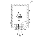
真空容器9は、透過型X線発生管10の内部を真空に保つためのもので、ガラスやセラミクス材料等が用いられる。真空容器9内の真空度は10-4〜10-8Pa程度である。真空容器9は開口部を有しており、その開口部には電子通過路4を形成するための電子通過路形成部材3が接合されている。図1及び図2に示されるように、この電子通過路4の端面に、透過型ターゲット1(以下、単にターゲット1と略す)と支持基板2からなるターゲット部17が接合されることにより真空容器9が密閉される。ターゲット1は、電子通過路形成部材3と電気的に導通している。また、真空容器9には不図示の排気管を設けても良い。排気管を設けた場合、例えば排気管を通じて真空容器9内を真空に排気した後、排気管の一部を封止することで真空容器9の内部を真空にすることができる。真空容器9の内部には真空度を保つために、不図示のゲッターを配置しても良い。 The vacuum container 9 is for keeping the inside of the transmission X-ray generator tube 10 in a vacuum, and glass, ceramic material, or the like is used. The degree of vacuum in the vacuum vessel 9 is about 10 −4 to 10 −8 Pa. The vacuum container 9 has an opening, and an electron passage forming member 3 for forming the electron passage 4 is joined to the opening. As shown in FIG. 1 and FIG. 2, a vacuum container is obtained by joining a transmission target 1 (hereinafter simply abbreviated as a target 1) and a target portion 17 made of a support substrate 2 to the end face of the electron passage 4. 9 is sealed. The target 1 is electrically connected to the electron passage forming member 3. The vacuum vessel 9 may be provided with an exhaust pipe (not shown). When the exhaust pipe is provided, for example, after the inside of the vacuum vessel 9 is evacuated through the exhaust pipe, the inside of the vacuum vessel 9 can be evacuated by sealing a part of the exhaust pipe. In order to keep the degree of vacuum inside the vacuum vessel 9, a getter (not shown) may be arranged.

電子放出源6は、真空容器9の内部に、ターゲット1に対向して配置されている。電子放出源6にはタングステンフィラメントや、含浸型カソードのような熱陰極、又はカーボンナノチューブ等の冷陰極を用いることができる。電子放出源6より放出された電子線11は、電子通過路形成部材3により形成された電子通過路4の一端から入射して電子通過路4内を通過し、電子通過路4の他端側に設けられたターゲット1に照射される。ターゲット1に電子線11が照射されることにより、X線13が発生し、発生したX線は真空容器9の外部に取出される。透過型X線発生管10には、引出し電極7と集束電極8が設けられている。引出し電極7によって形成される電界によって電子放出源6から電子が放出され、放出された電子は集束電極8で収束され、ターゲット1に入射する。このとき、電子放出源6とターゲット1との間に印加される電圧Vaは、X線の使用用途によって異なるものの、概ね40kV〜150kV程度である。   The electron emission source 6 is disposed inside the vacuum container 9 so as to face the target 1. The electron emission source 6 can be a tungsten filament, a hot cathode such as an impregnated cathode, or a cold cathode such as carbon nanotube. The electron beam 11 emitted from the electron emission source 6 is incident from one end of the electron passage 4 formed by the electron passage formation member 3 and passes through the electron passage 4, and the other end side of the electron passage 4. The target 1 provided on is irradiated. By irradiating the target 1 with the electron beam 11, X-rays 13 are generated, and the generated X-rays are taken out of the vacuum vessel 9. The transmission X-ray generator tube 10 is provided with an extraction electrode 7 and a focusing electrode 8. Electrons are emitted from the electron emission source 6 by the electric field formed by the extraction electrode 7, and the emitted electrons are converged by the focusing electrode 8 and enter the target 1. At this time, the voltage Va applied between the electron emission source 6 and the target 1 is approximately 40 kV to 150 kV although it varies depending on the intended use of the X-ray.

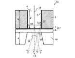
ターゲット1は、支持基板2の電子放出源側の面に配置されている。ターゲット1と電子放出源6の間には、電子通過路形成部材3が配置され、周囲を電子通過路形成部材3で囲むことにより両端が開口した電子通過路4が形成されている。電子通過路形成部材3の内壁面は、副X線発生面5となっている。副X線発生面5は、電子通過路形成部材3の内壁面の一部として形成されていても良いし、電子通過路形成部材3の表面に電子通過路形成部材3とは別部材で形成されていても良い。   The target 1 is disposed on the surface of the support substrate 2 on the electron emission source side. An electron passage forming member 3 is disposed between the target 1 and the electron emission source 6, and an electron passage 4 having both ends opened by surrounding the periphery with the electron passage forming member 3 is formed. The inner wall surface of the electron passage forming member 3 is a sub X-ray generation surface 5. The secondary X-ray generation surface 5 may be formed as a part of the inner wall surface of the electron passage forming member 3 or formed on the surface of the electron passage forming member 3 as a member different from the electron passage forming member 3. May be.

図1及び図2の構成において、電子放出源6から放出された電子線11は、電子通過路4を介してターゲット1に衝突する。加速された電子がターゲット1に衝突することでX線が発生し、この時発生したX線は、支持基板2を透過して透過型X線発生管10の外部に放出される。また、ターゲット1に電子が衝突した際には、X線が発生するとともに、反射電子も発生する。ターゲット1は原子番号が40以上の材料(金属)で構成されるため、電子の反射率は20〜60%と比較的大きい。ターゲット1で生成された反射電子は、副X線発生面5に衝突しX線を発生する。この時発生したX線(以下、「副X線」という)は、支持基板2を透過して透過型X線発生管10の外部に放出される。即ち、副X線発生面5に反射電子が照射されることで生じるX線の少なくとも一部が、ターゲット1に直接電子が照射されたことで生じるX線に重畳されて、支持基板2を透過して透過型X線発生管10の外部に放出される。   1 and 2, the electron beam 11 emitted from the electron emission source 6 collides with the target 1 through the electron passage 4. The accelerated electrons collide with the target 1 to generate X-rays. The X-rays generated at this time are transmitted through the support substrate 2 and emitted to the outside of the transmission X-ray generator tube 10. Further, when electrons collide with the target 1, X-rays are generated and reflected electrons are also generated. Since the target 1 is made of a material (metal) having an atomic number of 40 or more, the reflectivity of electrons is relatively high at 20 to 60%. The reflected electrons generated by the target 1 collide with the secondary X-ray generation surface 5 and generate X-rays. X-rays generated at this time (hereinafter referred to as “sub-X-rays”) pass through the support substrate 2 and are emitted to the outside of the transmissive X-ray generation tube 10. That is, at least a part of the X-rays generated when the sub-X-ray generation surface 5 is irradiated with the reflected electrons are superimposed on the X-rays generated when the target 1 is directly irradiated with the electrons and transmitted through the support substrate 2. Then, it is emitted to the outside of the transmission type X-ray generator tube 10.

図3に示すように、本例のアノード16は、ターゲット部17(ターゲット1、支持基板2)、電子通過路形成部材3、遮蔽部材18により構成される。   As shown in FIG. 3, the anode 16 of this example includes a target portion 17 (target 1, support substrate 2), an electron passage formation member 3, and a shielding member 18.

ターゲット1の材料は、通常、原子番号26以上の金属材料を用いることができる。より好適には、熱伝導率が大きく、比熱が大きいものほど良い。また、ターゲット1の膜厚は、発生したX線が透過する厚さでなければならず、加速電圧によって電子線浸入深さすなわちX線の発生領域が異なるため最適な値は異なるが、1μm〜15μmである。支持基板2はダイヤモンド等を用いることができ、その厚みは、0.5mm〜5mmが適当である。   As the material of the target 1, a metal material having an atomic number of 26 or more can be usually used. More preferably, the higher the thermal conductivity and the higher the specific heat, the better. The film thickness of the target 1 must be a thickness through which the generated X-rays are transmitted, and the optimum value varies depending on the acceleration voltage, that is, the electron beam penetration depth, that is, the X-ray generation region differs. 15 μm. The support substrate 2 can use diamond or the like, and the thickness is suitably 0.5 mm to 5 mm.

遮蔽部材18は、必須の部材ではないが、前方(ターゲット1から電子放出源6とは反対の方向)へ向かって放出されたX線のうち、必要とされるX線を開口から取り出し、不要なX線を遮蔽する機能を有する。遮蔽部材18に用いることができる材質は、40kV〜150kVで発生するX線を遮蔽できるものであれば良く、X線の吸収率が高く、かつ熱伝導率の高いものが好ましい。好適には、ターゲット1にタングステンを用いた場合、遮蔽部材18にはタングステン、タンタル等、またはこれらの合金材料を用いることができる。ターゲット1にモリブデンを用いた場合、遮蔽部材18にはタングステン、タンタルの他、モリブデン、ジルコニウム、ニオブ等を用いることができる。   Although the shielding member 18 is not an essential member, it is unnecessary to take out necessary X-rays out of the opening among X-rays emitted forward (in the direction opposite to the electron emission source 6 from the target 1). It has a function of shielding various X-rays. The material that can be used for the shielding member 18 may be any material that can shield X-rays generated at 40 kV to 150 kV, and preferably has a high X-ray absorption rate and a high thermal conductivity. Preferably, when tungsten is used for the target 1, tungsten, tantalum, or an alloy material thereof can be used for the shielding member 18. When molybdenum is used for the target 1, molybdenum, zirconium, niobium, or the like can be used for the shielding member 18 in addition to tungsten and tantalum.

遮蔽部材18の開口の形状は、円形であっても角形であっても良い。遮蔽部材18の開口の大きさは、少なくとも必要なX線が取り出せる大きさが必要である。開口の形状が円形の場合には直径0.1mm〜3mmが好ましく、開口の形状が角形の場合には1辺が0.1mm〜3mmが好ましい。これは、0.1mm以下では実質的に撮像時のX線量が少なくなり使用しにくく、3mm以上では実質的に遮蔽体18への放熱効果が得られにくいからである。   The shape of the opening of the shielding member 18 may be circular or rectangular. The size of the opening of the shielding member 18 must be at least large enough to extract necessary X-rays. When the shape of the opening is circular, the diameter is preferably 0.1 mm to 3 mm, and when the shape of the opening is square, one side is preferably 0.1 mm to 3 mm. This is because if the thickness is 0.1 mm or less, the X-ray dose at the time of imaging is substantially reduced and it is difficult to use, and if it is 3 mm or more, the heat dissipation effect to the shield 18 is hardly obtained.

また、遮蔽部材18の開口は、前方に向かって徐々に広がっていることが望ましい。すなわち、遮蔽部材18のターゲット側開口端から、遮蔽部材18のターゲット1とは反対側の開口端に向かって徐々に広がっていることが望ましい。これは、ターゲット側開口端が狭いとターゲット1で発生した熱がより速やかに遮蔽部材18に伝わって放熱でき、かつターゲット1とは反対側の開口端が広いと撮像時のX線の照射領域を広くすることができるからである。   Moreover, it is desirable that the opening of the shielding member 18 gradually widens toward the front. That is, it is desirable that the shielding member 18 gradually spreads from the target-side opening end toward the opening end of the shielding member 18 opposite to the target 1. This is because if the target-side opening end is narrow, the heat generated in the target 1 is transmitted to the shielding member 18 more quickly and can be dissipated, and if the opening end opposite to the target 1 is wide, the X-ray irradiation region during imaging This is because it can be widened.

遮蔽部材18の厚さaは、発生したX線を実質的に問題ない範囲まで減少させる遮蔽効果を有する厚さであれば良い。この厚さは、発生するX線のエネルギーによって異なる。例えば、X線のエネルギーが30keV〜150keVの場合、遮蔽効果の大きいタングステンでも、少なくとも1mm〜3mmは必要である。X線を遮蔽する観点からはこれ以上の厚さであれば問題ないが、熱容量、コスト、重量の観点からは3mm〜10mmがより好ましい。   The thickness a of the shielding member 18 may be any thickness that has a shielding effect that reduces the generated X-rays to a range where there is substantially no problem. This thickness varies depending on the energy of the generated X-rays. For example, when the energy of the X-ray is 30 keV to 150 keV, at least 1 mm to 3 mm is necessary even for tungsten having a large shielding effect. From the viewpoint of shielding X-rays, there is no problem as long as the thickness is greater than this, but from the viewpoint of heat capacity, cost, and weight, 3 mm to 10 mm is more preferable.

電子通過路形成部材3は、副X線発生面5として機能する以外に、後方(ターゲット1から電子放出源側に向かう方向)へ向かって放出されるX線を遮蔽する機能を有する。但し、電子通過路形成部材3の開口を通過して電子放出源側に放出されるX線は遮蔽できないため、別途遮蔽手段を設けてもよい。   In addition to functioning as the secondary X-ray generation surface 5, the electron passage formation member 3 has a function of shielding X-rays emitted backward (in the direction from the target 1 toward the electron emission source). However, since X-rays that pass through the opening of the electron passage forming member 3 and are emitted toward the electron emission source cannot be shielded, separate shielding means may be provided.

ターゲット1で反射した反射電子により発生する副X線を効率的に発生させると共に、ターゲット1で発生するX線と特性を等しくするためには、ターゲット1の材料と、少なくとも電子通過路形成部材3の副X線発生面5の構成材料との組み合わせが重要である。   In order to efficiently generate the secondary X-rays generated by the reflected electrons reflected by the target 1 and to make the characteristics equal to those of the X-rays generated by the target 1, at least the electron passage formation member 3. The combination with the constituent material of the secondary X-ray generation surface 5 is important.

ターゲット1に衝突した電子の一部は、入射した時のエネルギーの一部を失い、反射電子となって、電子通過路形成部材3の副X線発生面5に衝突する。ターゲット1に直接衝突する電子には所望の電圧が印加されているが、反射電子はエネルギーの一部を失って、ターゲット1への入射電圧以下の電圧になっている。X線の発生は、電圧、電流、電子線が照射される材料によって影響を受けるため、反射電子によるX線の発生効率を高めるためには、少なくとも電子通過路形成部材3の副X線発生面5を構成する材料は、原子番号が40以上の材料であることが必要である。また、ターゲット1で発生するX線と特性を等しくするためには、少なくとも電子通過路形成部材3の副X線発生面5を構成する材料はターゲット1の材料と同じ材料であることが必要である。ターゲット1の材料と電子通過路形成部材3の材料としては、Mo、W、ランタノイドのいずれかを好ましく用いることができる。   Some of the electrons that collide with the target 1 lose some of the energy when they are incident, become reflected electrons, and collide with the secondary X-ray generation surface 5 of the electron passage forming member 3. Although a desired voltage is applied to the electrons that directly collide with the target 1, the reflected electrons lose a part of their energy and become a voltage equal to or lower than the incident voltage to the target 1. Since the generation of X-rays is affected by the voltage, current, and material irradiated with the electron beam, at least the sub-X-ray generation surface of the electron passage forming member 3 is required to increase the generation efficiency of the X-rays by the reflected electrons. 5 is required to be a material having an atomic number of 40 or more. Further, in order to equalize the characteristics with the X-rays generated at the target 1, at least the material constituting the sub-X-ray generation surface 5 of the electron passage forming member 3 needs to be the same material as the material of the target 1. is there. As the material of the target 1 and the material of the electron passage forming member 3, any of Mo, W, and lanthanoid can be preferably used.

本例の電子通過路形成部材3と副X線発生面5は一体的に同じ材料で構成されているが、電子通過路形成部材3の上に電子通過路形成部材3とは異なる材料の副X線発生面5が形成されていてもよい。例えば、ターゲット1の材料と副X線発生面5の構成材料をWとし、電子通過路形成部材3の材料を銅(Cu)とすることができる。このとき、副X線発生面5の厚みは、電子の侵入長以上であることが好ましく、1μm〜100μmが好ましい。   In this example, the electron passage forming member 3 and the sub X-ray generation surface 5 are integrally made of the same material, but a sub-material of a material different from the electron passage forming member 3 is formed on the electron passage forming member 3. An X-ray generation surface 5 may be formed. For example, the material of the target 1 and the constituent material of the sub X-ray generation surface 5 can be W, and the material of the electron passage forming member 3 can be copper (Cu). At this time, the thickness of the sub-X-ray generation surface 5 is preferably not less than the penetration length of electrons, and preferably 1 μm to 100 μm.

ここで、副X線発生面5が形成される領域の好ましい範囲について説明する。図3において、電子通過路4の断面形状を円形とした場合、その大きさ(半径=R)と電子通過路4の路長Z(副X線発生面5のターゲット1からの形成距離)の好ましい範囲について述べる。路長Zの好ましい範囲は、ターゲット1で発生した反射電子の周辺部への到達密度分布を考慮して設定することができる。ターゲット1で反射した反射電子の到達点は、ターゲット1からの距離Zが2R以下の電子通過路内の周辺部表面に多く存在し、全体の80%程度が存在する。また、距離Zが4R以下では全体の95%程度が存在する。さらに、距離Zが20Rになると、反射電子の到達密度は、ほぼゼロに集束する。従って、電子通過路4の開口幅(電子通過路形成部材3の開口の大きさ)を2Rとした時に、距離Zが少なくとも2R以下、好ましくは4R以下の領域には副X線発生面5が形成されていることが望ましい。従って、電子通過路形成部材3の開口の大きさ2Rと電子通過路の路長Zは(2R≦Z≦20R)の関係を満たすことが望ましい。さらに、好ましくは、(4R≦Z≦20R)の関係を満たすことが望ましい。本実施形態では、路長Zは電子通過路形成部材3の厚さbに等しい。   Here, a preferable range of the region where the sub X-ray generation surface 5 is formed will be described. In FIG. 3, when the cross-sectional shape of the electron passage 4 is circular, the size (radius = R) and the length Z of the electron passage 4 (the formation distance of the sub X-ray generation surface 5 from the target 1) A preferred range will be described. A preferable range of the path length Z can be set in consideration of the density distribution of the reflected electrons generated at the target 1 to the peripheral portion. There are many arrival points of the reflected electrons reflected by the target 1 on the surface of the peripheral portion in the electron passage where the distance Z from the target 1 is 2R or less, and about 80% of the total. Further, when the distance Z is 4R or less, there is about 95% of the total. Further, when the distance Z becomes 20R, the arrival density of the reflected electrons is converged to almost zero. Accordingly, when the opening width of the electron passage 4 (the size of the opening of the electron passage formation member 3) is 2R, the sub-X-ray generation surface 5 is located in a region where the distance Z is at least 2R, preferably 4R or less. It is desirable that it be formed. Accordingly, it is desirable that the size 2R of the opening of the electron passage forming member 3 and the path length Z of the electron passage pass the relationship (2R ≦ Z ≦ 20R). Furthermore, it is preferable that the relationship (4R ≦ Z ≦ 20R) is satisfied. In this embodiment, the path length Z is equal to the thickness b of the electron passage path forming member 3.

一方、電子通過路4の開口の大きさは、少なくとも電子線11がこの開口の中に入る大きさが必要である。その大きさは、電子放出源6の種類や集束電極8の種類により電子線11の集束状態が異なるため一意的には決まらないが、電子通過路4の断面形状を円形とすると、その直径は、0.5mm〜5.0mmであることが好ましい。また、電子通過路形成部材3の厚さbは、X線の遮蔽効果を得るためには1mm以上は必要であることから、1mm〜25mmが好適である。   On the other hand, the size of the opening of the electron passage 4 needs to be at least large enough for the electron beam 11 to enter the opening. The size is not uniquely determined because the focusing state of the electron beam 11 differs depending on the type of the electron emission source 6 and the type of the focusing electrode 8, but if the cross-sectional shape of the electron passage 4 is circular, the diameter is It is preferable that it is 0.5 mm-5.0 mm. In addition, the thickness b of the electron passage forming member 3 is preferably 1 mm to 25 mm because 1 mm or more is necessary in order to obtain an X-ray shielding effect.

電子通過路形成部材3の開口の形状は、円形以外に正多角形とすることもできる。これは、電子線11の断面の形状が、円形または四角形であることが多く、ターゲット1の電子線照射領域から電子通過路形成部材3までの距離をできるだけ等しくするためである。   The shape of the opening of the electron passage forming member 3 can be a regular polygon other than a circle. This is because the cross-sectional shape of the electron beam 11 is often circular or quadrangular, and the distance from the electron beam irradiation region of the target 1 to the electron passage forming member 3 is made as equal as possible.

遮蔽部材18とターゲット部17との接合及びターゲット部17と電子通過路形成部材3との接合は、ロウ附けや、機械的な加圧、ねじ締め等により行うことができる。   The joining between the shielding member 18 and the target portion 17 and the joining between the target portion 17 and the electron passage forming member 3 can be performed by brazing, mechanical pressurization, screw tightening, or the like.

次に、図4を用いて第二の例に係るアノード16の構成及びX線の発生メカニズムについて説明する。   Next, the configuration of the anode 16 and the X-ray generation mechanism according to the second example will be described with reference to FIG.

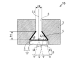
図4に示されるように、電子通過路4の断面積は、ターゲット1に向かって連続的に拡大している。具体的には、本例の電子通過路1のターゲット1側は、すり鉢状又はラッパ状にターゲット1に向かって連続的に拡大している。また、電子通過路4の断面積が拡大した領域の内壁面は、副X線発生面5となっている。尚、電子通過路4の断面積が拡大した領域の内壁面の少なくとも一部が副X線発生面5となっていれば良い。   As shown in FIG. 4, the cross-sectional area of the electron passage 4 continuously increases toward the target 1. Specifically, the target 1 side of the electron passage 1 of this example continuously expands toward the target 1 in a mortar shape or a trumpet shape. In addition, the inner wall surface of the region where the cross-sectional area of the electron passage 4 is enlarged serves as a secondary X-ray generation surface 5. It should be noted that at least part of the inner wall surface of the region where the cross-sectional area of the electron passage 4 is enlarged may be the sub X-ray generation surface 5.

次に、電子通過路4の好ましい形状について説明する。副X線発生面5とターゲット1とのなす角度θの好ましい範囲について述べる。θ>90°では、発生したX線15の多くが副X線発生面5内を通過中に吸収され、外部にはわずかしか放出されない。θ=90°では、発生したX線15の半分程度が副X線発生面5内で吸収される。θ<90°では、発生したX線15の多く(少なくとも半分程度以上)が吸収されずに外部に放出される。よって、θ<90°、即ち電子通過路4のターゲット1側の端部における断面積が、ターゲット1とは反対側に比して拡大した形状とすることで、発生したX線15が副X線発生面5内で吸収される割合を低減し、X線15の取り出し量を増大できる。   Next, a preferable shape of the electron passage 4 will be described. A preferable range of the angle θ formed by the sub X-ray generation surface 5 and the target 1 will be described. When θ> 90 °, most of the generated X-rays 15 are absorbed while passing through the sub-X-ray generation surface 5 and only slightly emitted to the outside. At θ = 90 °, about half of the generated X-ray 15 is absorbed in the sub-X-ray generation surface 5. When θ <90 °, most of the generated X-rays 15 (at least about half or more) are not absorbed and emitted to the outside. Therefore, θ <90 °, that is, the cross-sectional area at the end of the electron passage 4 on the target 1 side is enlarged as compared with the side opposite to the target 1, so that the generated X-rays 15 are sub-X. It is possible to reduce the rate of absorption in the ray generation surface 5 and increase the amount of X-ray 15 extracted.

また、X線強度の出射角度依存を考慮して、角度θの好ましい範囲を設定することもできる。一般に10kV〜200kVに加速された電子は、入射角度に強く依存することなく、副X線発生面5の数μm程度内部に侵入するため、副X線も副X線発生面5表面から数μm程度内側で多く発生する。発生する副X線は様々な角度に放出されるが、副X線の出射角度φ(副X線発生面5の表面からの角度)が小さい場合、副X線発生面5内部を通過する距離が長くなる。そのため、例えばφ<5°では、φが小さくなるに従って、X線強度が急激に小さくなる。従って、X線強度の出射角度依存性を考慮して出射角度の下限をφ0とした場合、角度θの好ましい範囲は、前述の好ましい範囲と合わせると、θ<90−φ0となる。φ0を5°とすると、θ<85°となる。また、ターゲットで反射された電子を内壁面に効率良く衝突させるための限界値を考慮すると、θの下限は10°<θとなる。よって、角度θの好ましい範囲は10°<θ<85°である。 In addition, a preferable range of the angle θ can be set in consideration of the emission angle dependence of the X-ray intensity. In general, electrons accelerated to 10 kV to 200 kV penetrate into the sub X-ray generation surface 5 about several μm without strongly depending on the incident angle, so that the sub X-rays are several μm from the surface of the sub X-ray generation surface 5. It often occurs inside. The generated sub-X-rays are emitted at various angles, but when the sub-X-ray emission angle φ (angle from the surface of the sub-X-ray generation surface 5) is small, the distance that passes through the sub-X-ray generation surface 5 Becomes longer. Therefore, for example, when φ <5 °, the X-ray intensity decreases rapidly as φ decreases. Accordingly, when the lower limit of the emission angle is set to φ 0 in consideration of the emission angle dependency of the X-ray intensity, the preferable range of the angle θ is θ <90−φ 0 when combined with the above-described preferable range. When the phi 0 and 5 °, the theta <85 °. Further, considering the limit value for efficiently colliding the electrons reflected by the target with the inner wall surface, the lower limit of θ is 10 ° <θ. Therefore, a preferable range of the angle θ is 10 ° <θ <85 °.

図1〜図3で説明した第一の例に係るアノード16と同様に、本例においても、電子通過路4の開口の大きさ2Rと副X線発生面5のターゲット1からの形成長さZは(2R≦Z≦20R)の関係を満たすことが望ましい。さらに、好ましくは、(4R≦Z≦20R)の関係を満たすことが望ましい。   Similar to the anode 16 according to the first example described with reference to FIGS. 1 to 3, the size 2R of the opening of the electron passage 4 and the formation length of the sub X-ray generation surface 5 from the target 1 are also provided in this example. Z preferably satisfies the relationship (2R ≦ Z ≦ 20R). Furthermore, it is preferable that the relationship (4R ≦ Z ≦ 20R) is satisfied.

尚、図4では、副X線発生面5は電子通過路4の断面積が拡大した領域の内壁全面に形成されているが、副X線発生面5は必ずしも電子通過路4の断面積が拡大した領域の内壁全面に形成されていなくても良い。少なくとも上記好ましい距離Zの範囲を含む領域に形成されていれば良い。   In FIG. 4, the secondary X-ray generation surface 5 is formed on the entire inner wall of the region where the cross-sectional area of the electron passage 4 is enlarged, but the secondary X-ray generation surface 5 does not necessarily have the cross-sectional area of the electron passage 4. It does not have to be formed on the entire inner wall of the enlarged region. It may be formed in a region including at least the preferable distance Z.

また、電子通過路4内に設けられた副X線発生面5に、反射電子12を衝突させて副X線を発生させ、副X線を透過型X線発生管10(図1参照)の外部に取り出す構成とするためには、副X線発生面5とターゲット1を次のように配置すれば良い。例えば、副X線発生面5を、ターゲット1の電子が照射される側の上方を覆うように張り出して配置すれば良い。他にも、ターゲット1に直接電子が照射されることにより発生するX線と副X線とが重畳されて外部に取出し可能となるように、副X線発生面5とターゲット1を配置すれば良い。この配置の場合、ターゲット1としては、照射された電子の20%〜60%を反射する材料を用いることができる。これらの配置の場合でも、副X線発生面5は、電子通過路形成部材3と同じ材料で形成されていても良いし、電子通過路形成部材3とは異なる材料で形成されていても良い。   Moreover, the reflected X-rays 12 collide with the secondary X-ray generation surface 5 provided in the electron passage 4 to generate secondary X-rays, and the secondary X-rays are transmitted to the transmission X-ray generator tube 10 (see FIG. 1). In order to adopt a configuration for taking out to the outside, the sub X-ray generation surface 5 and the target 1 may be arranged as follows. For example, the sub-X-ray generation surface 5 may be disposed so as to protrude above the electron irradiation side of the target 1. In addition, if the sub-X-ray generation surface 5 and the target 1 are arranged so that X-rays generated by direct irradiation of electrons on the target 1 and sub-X-rays are superimposed and can be taken out to the outside. good. In this arrangement, the target 1 can be made of a material that reflects 20% to 60% of the irradiated electrons. Even in these arrangements, the sub-X-ray generation surface 5 may be formed of the same material as the electron passage formation member 3 or may be formed of a material different from that of the electron passage formation member 3. .

副X線発生面5の形態は、副X線発生面5に反射電子が照射されることで生じたX線であって、ターゲット1の電子が照射される領域を透過するX線量を増大させる形態としておくことが好ましい。   The form of the secondary X-ray generation surface 5 is an X-ray generated by irradiating the secondary X-ray generation surface 5 with the reflected electrons, and increases the X-ray dose transmitted through the region irradiated with the electrons of the target 1. It is preferable to keep the form.

図4に示される例で用いられるターゲット1、支持基板2、電子通過路形成部材3の材料や形状は図1〜図3で説明した第一の例と同じである。また、第一の例に係るアノード16と同様に、電子通過路形成部材3の表面に電子通過路形成部材3とは異なる材料の副X線発生面5が形成されていてもよい。   The materials and shapes of the target 1, the support substrate 2, and the electron passage formation member 3 used in the example shown in FIG. 4 are the same as those in the first example described with reference to FIGS. Further, similarly to the anode 16 according to the first example, the secondary X-ray generation surface 5 made of a material different from that of the electron passage formation member 3 may be formed on the surface of the electron passage formation member 3.

以上、本例によれば、ターゲット1で発生するX線14に加えて、ターゲット1で発生した反射電子12により発生するX線15も、効率良く取り出す構成とすることにより、X線発生効率を向上させることが可能となる。   As described above, according to this example, in addition to the X-rays 14 generated at the target 1, the X-rays 15 generated by the reflected electrons 12 generated at the target 1 are also efficiently extracted, thereby improving the X-ray generation efficiency. It becomes possible to improve.

図5は、上記第二の例の変形例を示している。この例では、電子通過路形成部材3に形成された電子通過路4の形状が、上記第二の例と異なっている。即ち、本例における電子通過路4は、ターゲット1側が半球状となっている。電子通過路形成部材3及び電子通過路4の形状以外は、上記第二の例と同様とすることができる。この場合も上記第二の例と同様の効果が得られる。   FIG. 5 shows a modification of the second example. In this example, the shape of the electron passage 4 formed in the electron passage formation member 3 is different from the second example. That is, the electron passage 4 in this example is hemispherical on the target 1 side. Except for the shapes of the electron passage forming member 3 and the electron passage 4, it can be the same as the second example. In this case, the same effect as in the second example can be obtained.

図6は、第三の例に係るアノード16を示している。アノード16は、X線透過窓を兼ねる支持基板2と、導電層60と、ターゲット1と、電子通過路形成部材3とで構成される。   FIG. 6 shows an anode 16 according to a third example. The anode 16 includes a support substrate 2 that also serves as an X-ray transmission window, a conductive layer 60, a target 1, and an electron passage formation member 3.

支持基板2は、ダイヤモンド、窒化ケイ素、炭化ケイ素、炭化アルミ、窒化アルミ、グラファイト、ベリリウム等を用いることができる。より好ましくは、X線の透過率がアルミニウムよりも小さく熱伝導率がタングステンよりも大きい、ダイヤモンドが望ましい。支持基板2の厚さは、材料によって異なるが、0.3mm〜2mmが好ましい。   As the support substrate 2, diamond, silicon nitride, silicon carbide, aluminum carbide, aluminum nitride, graphite, beryllium, or the like can be used. More preferably, diamond having X-ray transmittance smaller than aluminum and thermal conductivity larger than tungsten is desirable. Although the thickness of the support substrate 2 changes with materials, 0.3 mm-2 mm are preferable.

導電層19は、電子線11がターゲット1に照射され、電子によるターゲット部17のチャージアップを防ぐ目的で設けられるため、導電性を有するものであれば良く、多くの金属材料又は炭化物、酸化物等を用いることができる。支持基板2への導電層19の成膜は、スパッタ、蒸着によって行われる。支持基板2がグラファイトやベリリウムのような導電体、又は絶縁体に添加物によって導電性を付与できる材料であれば、導電層19は不要である。しかし、通常、市販されているダイヤモンドのような絶縁体では、導電性がないため、導電層19を設ける必要がある。また、導電層19を設けることにより、導電層19を介してターゲット1に電圧を供給することもできる。   The conductive layer 19 is provided for the purpose of preventing the target 1 from being charged up by the electron beam 11 being irradiated with the electron beam 11, so that the conductive layer 19 only needs to have conductivity, and many metal materials, carbides, oxides Etc. can be used. The conductive layer 19 is formed on the support substrate 2 by sputtering or vapor deposition. If the support substrate 2 is a material that can impart conductivity to an insulator such as graphite or beryllium, or an insulator, the conductive layer 19 is not necessary. However, since a commercially available insulator such as diamond does not have conductivity, it is necessary to provide the conductive layer 19. In addition, by providing the conductive layer 19, a voltage can be supplied to the target 1 through the conductive layer 19.

導電層19がターゲット部17のチャージアップを防ぐことのみを目的とするのであれば、導電性を有していれば、材料の種類や厚さに何ら制限はない。しかし、本実施形態では、導電層19には、電子通過路形成部材3に形成された電子通過路4の内壁面で発生する副X線を外部に取り出すための機能を持たせることを目的としているため、材料の種類や厚さについても影響を受ける。   If the conductive layer 19 is only intended to prevent the target portion 17 from being charged up, there is no limitation on the type and thickness of the material as long as it has conductivity. However, in the present embodiment, for the purpose of providing the conductive layer 19 with a function for taking out secondary X-rays generated on the inner wall surface of the electron passage 4 formed on the electron passage formation member 3 to the outside. Therefore, the type and thickness of the material are also affected.

本例で用いられるターゲット1及び電子通過路形成部材3の材料や形状は前記第一の例に係るアノード16と同じである。また、第一の例と同様に、電子通過路形成部材3とは異なる材料で副X線発生面5が形成されていてもよい。   The materials and shapes of the target 1 and the electron passage forming member 3 used in this example are the same as those of the anode 16 according to the first example. Similarly to the first example, the sub X-ray generation surface 5 may be formed of a material different from that of the electron passage forming member 3.

第一の例に係るアノード16と同様に、電子通過路形成部材3は、両端が開口した電子通過路4を有し、電子通過路4の一端(電子放出源6側の端部の開口部)から電子が入射し、電子通過路4の他端側(電子放出源6と反対側)に設けられたターゲット1に電子が照射されてX線が発生する。電子通過路4は、ターゲット1よりも電子放出源6側では、電子線11をターゲット1の電子線照射領域(X線発生領域)に導くための通過路になっている。電子通過路4は、電子放出源6側から見たときの形状が円形でも良いし、四角形や楕円形等適宜、選択することができる。また、電子通過路形成部材3は、ターゲット1に衝突して反射した電子を電子通過路4の副X線発生面5に衝突させ、副X線を発生させる機能も有している。   Similar to the anode 16 according to the first example, the electron passage forming member 3 includes an electron passage 4 having both ends opened, and one end of the electron passage 4 (an opening at the end on the electron emission source 6 side). ), The target 1 provided on the other end side (the side opposite to the electron emission source 6) of the electron passage 4 is irradiated with electrons, and X-rays are generated. The electron passage 4 is a passage for guiding the electron beam 11 to the electron beam irradiation region (X-ray generation region) of the target 1 on the electron emission source 6 side of the target 1. The electron passage 4 may have a circular shape when viewed from the electron emission source 6 side, and can be appropriately selected such as a quadrangle or an ellipse. The electron passage forming member 3 also has a function of causing the electrons reflected and collided with the target 1 to collide with the sub X-ray generation surface 5 of the electron passage 4 to generate sub X-rays.

本例におけるターゲット部17は、支持基板2上に導電層19を設け、導電層19上の中央領域にターゲット1を設けた構成をとる。図6において、d1はターゲット1の径、d2は電子通過路4の内径である。ターゲット部17と電子通過路形成部材3は不図示のロウ材によりロウ付けされ、真空容器9(図1参照)の内部が真空維持されている。図6(b)における破線より外側の領域の導電層19は、ターゲット部17と電子通過路形成部材3を一体化すると、電子通過路形成部材3によって覆われる。   The target unit 17 in this example has a configuration in which the conductive layer 19 is provided on the support substrate 2 and the target 1 is provided in the central region on the conductive layer 19. In FIG. 6, d 1 is the diameter of the target 1, and d 2 is the inner diameter of the electron passage 4. The target portion 17 and the electron passage path forming member 3 are brazed with a brazing material (not shown), and the inside of the vacuum vessel 9 (see FIG. 1) is maintained in vacuum. The conductive layer 19 in the region outside the broken line in FIG. 6B is covered with the electron passage formation member 3 when the target portion 17 and the electron passage formation member 3 are integrated.

電子放出源6から発生した電子線11は、電子通過路形成部材3により形成された電子通過路4を介してターゲット1に衝突し、ターゲット1からX線13が発生する。X線13の一部はターゲット1の自己吸収により減衰し、更にX線透過窓を兼ねる支持基板2によっても減衰するが、これらの減衰の程度は少なく、実質上、許容される。ターゲット1の径d1は、電子線11の断面の径にほぼ等しいことが望ましい。   The electron beam 11 generated from the electron emission source 6 collides with the target 1 via the electron passage 4 formed by the electron passage formation member 3, and X-rays 13 are generated from the target 1. A part of the X-rays 13 is attenuated by the self-absorption of the target 1 and further attenuated by the support substrate 2 that also serves as an X-ray transmission window. However, the degree of these attenuations is small and substantially allowed. The diameter d1 of the target 1 is desirably substantially equal to the diameter of the cross section of the electron beam 11.

一方、ターゲット1に衝突した電子のうち、一部の電子は反射され、反射電子となって電子通過路4の内壁面に衝突し、内壁面から副X線を発生する。   On the other hand, some of the electrons that collide with the target 1 are reflected, become reflected electrons, collide with the inner wall surface of the electron passage 4, and generate secondary X-rays from the inner wall surface.

副X線がターゲット部17を透過するとき、導電層19、支持基板2の2層を透過するものと、ターゲット1、導電層19、支持基板2の3層を透過するものがある。ターゲット1は、電子を衝突させてX線を効率良く発生させる材料や厚さでなければならないので、使用条件に応じて最適化されていなければならない。一方、導電層60は、電子が衝突してX線を発生させることがほとんどないため、本来の機能である導電性と、X線透過性を考慮すれば良い。但し、副X線のエネルギーは、ターゲット1から放出されるX線のエネルギーに比べて小さいため、導電層60がターゲット1と同じ材質、同じ厚さであると、X線の吸収が大きくなり、充分に副X線を取り出すことができない場合がある。   When the secondary X-rays pass through the target portion 17, there are those that pass through two layers of the conductive layer 19 and the support substrate 2, and those that pass through three layers of the target 1, the conductive layer 19, and the support substrate 2. Since the target 1 must be made of a material or a thickness that can efficiently generate X-rays by colliding electrons, it must be optimized according to the use conditions. On the other hand, since the conductive layer 60 hardly generates X-rays due to collision of electrons, it is only necessary to consider conductivity and X-ray transparency, which are the original functions. However, since the energy of the secondary X-ray is smaller than the energy of the X-ray emitted from the target 1, if the conductive layer 60 is the same material and the same thickness as the target 1, X-ray absorption is increased. In some cases, the secondary X-rays cannot be extracted sufficiently.

導電層19に用いるX線透過性の良い材料としては、軽元素が望ましく、例えばアルミ、チタン、窒化ケイ素、シリコン、グラファイト等を用いることができる。ターゲット1に比して質量の軽いこれらの元素を用いた場合の導電層19の厚さは、0.1nm〜1μmが好ましい。導電層19の材料は、ターゲット1の材料と同じでも良い。導電層19の材料がターゲット1の材料と同じ場合、導電層19の厚さは、X線を透過させるために実質的に支障のない薄さであれば良い。一般的なターゲット1として通常用いられる原子番号26以上の金属材料であっても、その厚さが薄ければ、X線の透過率が高いため、導電層19として用いることができる。例えばタングステンを用いた場合には、0.1nm〜0.2μmであれば、X線を僅かに遮る程度であり、軽元素の場合と同様に用いることができる。   As the material having good X-ray transparency used for the conductive layer 19, a light element is desirable, and for example, aluminum, titanium, silicon nitride, silicon, graphite, or the like can be used. The thickness of the conductive layer 19 when these elements having a lighter mass than the target 1 are used is preferably 0.1 nm to 1 μm. The material of the conductive layer 19 may be the same as the material of the target 1. When the material of the conductive layer 19 is the same as the material of the target 1, the thickness of the conductive layer 19 may be a thickness that does not substantially hinder the transmission of X-rays. Even a metal material having an atomic number of 26 or more that is normally used as a general target 1 can be used as the conductive layer 19 because its X-ray transmittance is high if its thickness is small. For example, when tungsten is used, a thickness of 0.1 nm to 0.2 μm is sufficient to block X-rays slightly, and can be used in the same manner as in the case of light elements.

また、本例では、支持基板2上に導電層19、導電層19上にターゲット1を設けているが、この順でなくても良く、ターゲット1上から支持基板2上に跨るように導電層60を設けることもできる。   Further, in this example, the conductive layer 19 is provided on the support substrate 2 and the target 1 is provided on the conductive layer 19, but this order is not necessary, and the conductive layer extends from the target 1 to the support substrate 2. 60 can also be provided.

導電層19上にターゲット1を設けた場合には、ターゲット1で覆われた領域における導電層19の厚さを0.1nm〜0.1μmとするのが好ましい。この範囲の厚さにすることでX線放射時の良好な線形性と出力安定性を確保できるからである。尚、導電層19の厚さは、ターゲット1で覆われた領域以外では上記範囲でなくても良い。また、導電層19とターゲット1とが同じ材料の場合には、ターゲット1で覆われた領域における導電層60の厚さは上記範囲でなくても良い。   When the target 1 is provided on the conductive layer 19, the thickness of the conductive layer 19 in the region covered with the target 1 is preferably 0.1 nm to 0.1 μm. This is because by setting the thickness within this range, it is possible to ensure good linearity and output stability during X-ray emission. The thickness of the conductive layer 19 may not be in the above range except for the region covered with the target 1. When the conductive layer 19 and the target 1 are made of the same material, the thickness of the conductive layer 60 in the region covered with the target 1 may not be in the above range.

ターゲット1上に導電層19を設けた場合には、ターゲット1を覆う領域の導電層19の厚さを0.1nm〜0.1μmとするのが好ましい。この範囲の厚さにすることで電子が導電層19に直接衝突することにより発生するX線量が許容範囲以下になるからである。尚、導電層19の厚さは、ターゲット1を覆う領域以外では電子が導電層19に直接衝突しないため上記範囲でなくても良い。また、導電層19とターゲット1が同じ材料の場合には、ターゲット1を覆う領域の導電層19の厚さは上記範囲でなくても良い。   When the conductive layer 19 is provided on the target 1, the thickness of the conductive layer 19 in the region covering the target 1 is preferably 0.1 nm to 0.1 μm. This is because, by setting the thickness within this range, the X-ray dose generated when electrons directly collide with the conductive layer 19 becomes less than the allowable range. Note that the thickness of the conductive layer 19 does not have to be in the above range because electrons do not directly collide with the conductive layer 19 except in a region covering the target 1. When the conductive layer 19 and the target 1 are made of the same material, the thickness of the conductive layer 19 in the region covering the target 1 may not be in the above range.

図7は、図6に示されるターゲット部17の変形例に係るターゲット部17の断面図及び平面図(ターゲット部17をターゲット1側から見た図)である。   7 is a cross-sectional view and a plan view of the target unit 17 according to a modification of the target unit 17 shown in FIG. 6 (a view of the target unit 17 viewed from the target 1 side).

導電層19の形状が異なること以外は、図6の例と同じである。支持基板2上の中央領域に導電層19を設け、支持基板2上の中央領域以外の領域の一部にも中央領域から周縁に延びる導電層19を設けている。また、支持基板2の中央領域に位置する導電層19上にターゲット1を設けている。ターゲット1で覆われていない支持基板2上の周縁領域において、導電層19はこの周縁領域の一部に設けられており、この周縁領域のその他の部分は、支持基板2の露出面になっている。   Except that the shape of the conductive layer 19 is different, it is the same as the example of FIG. A conductive layer 19 is provided in the central region on the support substrate 2, and a conductive layer 19 extending from the central region to the periphery is also provided in a part of the region other than the central region on the support substrate 2. Further, the target 1 is provided on the conductive layer 19 located in the central region of the support substrate 2. In the peripheral region on the support substrate 2 not covered with the target 1, the conductive layer 19 is provided in a part of the peripheral region, and the other part of the peripheral region is an exposed surface of the support substrate 2. Yes.

本例によれば、ターゲット1で覆われていない支持基板2の周縁領域において、導電層19が覆っているのは一部だけであり、周縁領域の他の部分は支持基板2の露出面になっている。このため、この周縁領域における副X線の透過性が良好になる。従って、ターゲット1で発生した反射電子により発生する副X線も、効率良く取り出すことができる。これにより、X線発生効率を向上させることが可能となる。   According to this example, in the peripheral region of the support substrate 2 that is not covered with the target 1, the conductive layer 19 covers only a part, and the other part of the peripheral region is on the exposed surface of the support substrate 2. It has become. For this reason, the transmission of the sub-X-rays in this peripheral region is improved. Therefore, the secondary X-rays generated by the reflected electrons generated from the target 1 can also be extracted efficiently. Thereby, X-ray generation efficiency can be improved.

次に、図8を用いて透過型X線発生管を備えた本発明のX線発生装置について説明する。図8は本実施形態のX線発生装置の構成図である。   Next, the X-ray generator of the present invention provided with a transmission X-ray generator tube will be described with reference to FIG. FIG. 8 is a block diagram of the X-ray generator of this embodiment.

まず、本発明に用いられる透過型X線発生管10を備えたX線発生装置24について説明する。X線発生装置24は、外囲器20の内部に、透過型X線発生管10を収納している。外囲器20には、X線取出し窓21が備えられており、透過型X線発生管10より放出されたX線は、X線取出し窓21を透過して、X線発生装置24外部に放出される。   First, the X-ray generator 24 provided with the transmission X-ray generator tube 10 used in the present invention will be described. The X-ray generator 24 houses the transmissive X-ray generator tube 10 inside the envelope 20. The envelope 20 is provided with an X-ray extraction window 21, and X-rays emitted from the transmissive X-ray generation tube 10 pass through the X-ray extraction window 21 and go outside the X-ray generation device 24. Released.

外囲器20の内部に透過型X線発生管10を収納した余空間には絶縁性媒体23が充填されていても良い。絶縁性媒体23としては、例えば絶縁媒体及び透過型X線発生管10の冷却媒体としての役割を有する電気絶縁油を用いるのが好ましい。電気絶縁油としては、鉱油、シリコーン油等が好適に用いられる。その他に使用可能な絶縁性媒体23としては、フッ素系電気絶縁液体等が挙げられる。   The extra space in which the transmissive X-ray generator tube 10 is accommodated inside the envelope 20 may be filled with an insulating medium 23. As the insulating medium 23, it is preferable to use, for example, an insulating medium and an electric insulating oil that serves as a cooling medium for the transmission X-ray generator tube 10. As the electrical insulating oil, mineral oil, silicone oil or the like is preferably used. Other insulating media 23 that can be used include fluorine-based electrically insulating liquids.

また、外囲器20の内部には、本実施形態のように不図示の回路基板及び絶縁トランス等から構成される電圧制御部22を設けても良い。電圧制御部22を設けた場合、例えば透過型X線発生管10に、電圧制御部22から電圧信号が印加されX線の発生を制御することができる。   In addition, a voltage control unit 22 including a circuit board (not shown) and an insulating transformer may be provided inside the envelope 20 as in the present embodiment. When the voltage control unit 22 is provided, for example, a voltage signal is applied from the voltage control unit 22 to the transmission X-ray generation tube 10 to control generation of X-rays.

以上、本実施形態によれば、透過型ターゲット1で発生するX線14に加えて、透過型ターゲット1で発生した反射電子12により発生するX線15も取り出せるため、X線発生効率を向上させた透過型X線発生装置を実現できる。   As described above, according to the present embodiment, in addition to the X-rays 14 generated in the transmissive target 1, the X-rays 15 generated by the reflected electrons 12 generated in the transmissive target 1 can be extracted, so that the X-ray generation efficiency is improved. A transmission X-ray generator can be realized.

(実施例1)
図1〜図3で説明したような透過型X線発生管10を作成した。
Example 1
A transmission X-ray generator tube 10 as described with reference to FIGS.

高圧合成ダイヤモンドをターゲット1の支持基板2として用意した。高圧高温ダイヤモンドは、直径5mm、厚さ1mmのディスク状(円柱状)の形状である。予め、UV−オゾンアッシャにより、ダイヤモンドの表面にある有機物を除去した。   High-pressure synthetic diamond was prepared as a support substrate 2 for the target 1. The high-pressure and high-temperature diamond has a disk shape (columnar shape) having a diameter of 5 mm and a thickness of 1 mm. In advance, organic substances on the surface of the diamond were removed by a UV-ozone asher.

このダイヤモンド基板の一方の面上に、スパッタ法により、Arをキャリアガスとして、あらかじめ、チタン層を形成し、その後、ターゲット1として8μmの厚さのタングステン層を形成した。このようにして、ターゲット部17を得た。   A titanium layer was formed in advance on one surface of the diamond substrate by sputtering using Ar as a carrier gas, and then a tungsten layer having a thickness of 8 μm was formed as the target 1. Thus, the target part 17 was obtained.

このターゲット部17の周りにチタンを活性金属成分としたメタライズ層を形成し、その上に、銀、銅、チタンからなるろう材を付けた。   A metallized layer containing titanium as an active metal component was formed around the target portion 17, and a brazing material made of silver, copper, and titanium was attached thereon.

一方、電子通過路形成部材3としてタングステンの部材を用意し、ターゲット部17の保持部及び電子通過路4を形成した。保持部の直径は5.3mm、電子通過路4の半径R及び電子通過路4の長さZは、表1に条件1〜18として示すごとくパラメータとして異なる値で作製した。   On the other hand, a tungsten member was prepared as the electron passage forming member 3, and the holding portion of the target portion 17 and the electron passage 4 were formed. The diameter of the holding portion was 5.3 mm, the radius R of the electron passage 4 and the length Z of the electron passage 4 were made with different values as parameters as shown in Table 1 as Conditions 1-18.

ろう材を付けたターゲット部17を、上記のような形状に加工した電子通過路形成部材3にセットして、850℃で焼成し、アノード16を作製した。   The target part 17 to which the brazing material was attached was set on the electron passage forming member 3 processed into the shape as described above, and was fired at 850 ° C. to produce the anode 16.

次に、図1に示すように、ターゲット部17と電子通過路形成部材3を一体としたアノード16を、電子放出源6を有する含侵型の熱電子銃をターゲット1と対向させて、電子線11が電子通過路4の中に入るように位置決めした。そして、ゲッターを配置し、真空封止し、透過型X線発生管10を作製した。   Next, as shown in FIG. 1, an anode 16 in which a target portion 17 and an electron passage forming member 3 are integrated, and an impregnated thermoelectron gun having an electron emission source 6 is opposed to the target 1 to The wire 11 was positioned so as to enter the electron passage 4. And a getter was arrange | positioned and vacuum-sealed and the transmission type X-ray generator tube 10 was produced.

ターゲット部17は、支持基板2とその表面に形成されたターゲット1により構成される。ターゲット1は、電子通過路形成部材3と電気的に導通している。ターゲット1は、支持基板2の電子放出源6側の面に配置されている。ターゲット1と電子放出源6の間には、電子通過路形成部材3が配置され、周囲を電子通過路形成部材3で囲むことにより、両端が開口した電子通過路4が形成されている。電子通過路形成部材3の内壁面は、副X線発生面5となっている。   The target unit 17 includes the support substrate 2 and the target 1 formed on the surface thereof. The target 1 is electrically connected to the electron passage forming member 3. The target 1 is disposed on the surface of the support substrate 2 on the electron emission source 6 side. An electron passage forming member 3 is disposed between the target 1 and the electron emission source 6, and an electron passage 4 having both ends opened is formed by surrounding the periphery with the electron passage forming member 3. The inner wall surface of the electron passage forming member 3 is a sub X-ray generation surface 5.

また、比較のために、図1中の電子通過路形成部材3を設けない比較用透過型X線発生管も作製した(条件19)。最後に本発明の効果を確認するため、透過型X線発生管10及び比較用透過型X線発生管によって得られるX線量を測定した。このX線量の測定は電離箱方式の線量計で行った。透過型X線発生管10及び比較用透過型X線発生管の駆動は、加速電圧が100kVで、電流が5mA、照射時間が100msecで行った。電子線の直径は、0.3mmから2mmの間で、電子レンズにより制御した。   For comparison, a comparative transmission X-ray generator tube without the electron passage forming member 3 in FIG. 1 was also produced (condition 19). Finally, in order to confirm the effect of the present invention, the X-ray dose obtained by the transmission X-ray generator tube 10 and the comparative transmission X-ray generator tube was measured. The X-ray dose was measured with an ionization chamber type dosimeter. The transmission X-ray generator tube 10 and the comparative transmission X-ray generator tube were driven at an acceleration voltage of 100 kV, a current of 5 mA, and an irradiation time of 100 msec. The diameter of the electron beam was controlled by an electron lens between 0.3 mm and 2 mm.

表1は、比較用透過型X線発生管によって得られるX線量を100としたときの条件1から条件19までの透過型X線発生管10のX線量を示している。表1に示されるように、条件1から条件18(実施例)の全てにおいて、X線量が104〜164で、副X線の発生がない、電子通過路形成部材3のない条件19(比較例)に対し、より多くのX線が得られた。   Table 1 shows the X-ray dose of the transmission X-ray generator tube 10 from Condition 1 to Condition 19 when the X-ray dose obtained by the comparative transmission X-ray generator tube is 100. As shown in Table 1, in all of the conditions 1 to 18 (examples), the X-ray dose is 104 to 164, no secondary X-rays are generated, and the condition 19 without the electron passage forming member 3 (comparative example) ) More X-rays were obtained.

(実施例2)
次に、実施例2について説明する。
(Example 2)
Next, Example 2 will be described.

支持基板2は、実施例1と同様なダイヤモンド基板で、同様な処理をした。その後、ターゲット1として8μmの厚さのモリブデン層を形成した。このようにして、ターゲット部17を得た。尚、その他のターゲット部17の構成は実施例1と同様である。   The support substrate 2 was the same diamond substrate as in Example 1 and was subjected to the same treatment. Thereafter, a molybdenum layer having a thickness of 8 μm was formed as the target 1. Thus, the target part 17 was obtained. Other configurations of the target unit 17 are the same as those in the first embodiment.

このターゲット部17の周りにチタンを活性金属成分としたメタライズ層を形成し、その上に、銀、銅、チタンからなるろう材を付けた。   A metallized layer containing titanium as an active metal component was formed around the target portion 17, and a brazing material made of silver, copper, and titanium was attached thereon.

一方、電子通過路形成部材3としてモリブデン部材を用意し、実施例1と同様な寸法、形状とした。また、電子通過路4の半径Rと電子通過路の長さZは、表2に従って、条件20から条件37の寸法とし、さらに、実施例1と同様にアノード16を作製して、透過型X線発生管10を完成させた。また、比較のために、図1中の電子通過路形成部材3を設けない比較用透過型X線発生管も作製した(条件38)。この透過型X線発生管10及び比較用透過型X線発生管のX線量の測定は電離箱方式の線量計で行った。   On the other hand, a molybdenum member was prepared as the electron passage forming member 3 and had the same dimensions and shape as in Example 1. Further, the radius R of the electron passage 4 and the length Z of the electron passage are set to the dimensions of the conditions 20 to 37 in accordance with Table 2, and the anode 16 is manufactured in the same manner as in the first embodiment. The line generating tube 10 was completed. For comparison, a comparative transmission X-ray generator tube without the electron passage forming member 3 in FIG. 1 was also produced (condition 38). The X-ray dose of the transmission X-ray generator tube 10 and the comparative transmission X-ray generator tube was measured with an ionization chamber type dosimeter.

透過型X線発生管10及び比較用透過型X線発生管の駆動は、加速電圧が40kVで、電流が5mA、照射時間が100msecで行った。電子線の直径は、0.3mmから2mmの間で、電子レンズにより制御した。   The transmission X-ray generator tube 10 and the comparative transmission X-ray generator tube were driven at an acceleration voltage of 40 kV, a current of 5 mA, and an irradiation time of 100 msec. The diameter of the electron beam was controlled by an electron lens between 0.3 mm and 2 mm.

表2は、電子通過路形成部材3を設けない比較用透過型X線発生管によって得られるX線量を100としたときの条件20から条件38までの透過型X線発生管10のX線量を示している。表2に示されるように、条件20から条件37(実施例)の全てにおいて、X線量が103〜151で、副X線発生がしない電子通過路形成部材3のない条件38(比較例)に対してより多くのX線が得られた。   Table 2 shows the X-ray dose of the transmission X-ray generator tube 10 from the condition 20 to the condition 38 when the X-ray dose obtained by the comparative transmission X-ray generator tube without the electron passage forming member 3 is 100. Show. As shown in Table 2, in all of the conditions 20 to 37 (examples), the X-ray dose is 103 to 151, and the condition 38 (comparative example) without the electron passage forming member 3 that does not generate sub-X-rays. In contrast, more X-rays were obtained.

(実施例3)
次に、実施例3について説明する。
(Example 3)
Next, Example 3 will be described.

支持基板2は、実施例1と同様なダイヤモンド基板で、同様な処理をした。その後、ターゲット1として8μmの厚さのセリウム層を形成した。このようにして、ターゲット部17を得た。尚、その他のターゲット部17の構成は実施例1と同様である。   The support substrate 2 was the same diamond substrate as in Example 1 and was subjected to the same treatment. Thereafter, a cerium layer having a thickness of 8 μm was formed as the target 1. Thus, the target part 17 was obtained. Other configurations of the target unit 17 are the same as those in the first embodiment.

このターゲット部17の周りにチタンを活性金属成分としたメタライズ層を形成し、その上に、銀、銅、チタンからなるろう材を付けた。   A metallized layer containing titanium as an active metal component was formed around the target portion 17, and a brazing material made of silver, copper, and titanium was attached thereon.

一方、電子通過路形成部材3としてセリウム部材を用意し、実施例1と同様な寸法、形状とした。また、電子通過路4の半径Rと長さZは、表3に従って、条件39及び条件40の寸法で作製し、さらに、実施例1と同様にアノード16を作製して、透過型X線発生管10を完成させた。また、比較のために、図1中の電子通過路形成部材3を設けない比較用透過型X線発生管も作製した(条件41)。この透過型X線発生管10及び比較用透過型X線発生管のX線量の測定は電離箱方式の線量計で行った。   On the other hand, a cerium member was prepared as the electron passage forming member 3 and had the same dimensions and shape as in Example 1. Further, the radius R and the length Z of the electron passage 4 are prepared in accordance with the conditions 39 and 40 according to Table 3, and the anode 16 is prepared in the same manner as in Example 1 to generate transmission X-rays. Tube 10 was completed. For comparison, a comparative transmission X-ray generator tube without the electron passage forming member 3 in FIG. 1 was also produced (condition 41). The X-ray dose of the transmission X-ray generator tube 10 and the comparative transmission X-ray generator tube was measured with an ionization chamber type dosimeter.

透過型X線発生管10及び比較用透過型X線発生管の駆動は、加速電圧が40kVで、電流が5mA、照射時間が100msecで行った。電子線の直径は、0.3mmから2mmの間で、電子レンズにより制御した。   The transmission X-ray generator tube 10 and the comparative transmission X-ray generator tube were driven at an acceleration voltage of 40 kV, a current of 5 mA, and an irradiation time of 100 msec. The diameter of the electron beam was controlled by an electron lens between 0.3 mm and 2 mm.

表3は、電子通過路形成部材3を設けない比較用透過型X線発生管によって得られるX線量を100としたときの条件39と条件40の透過型X線発生管10のX線量を示している。表3に示されるように、条件39及び40(実施例)におけるX線量が150及び143で、反射電子を受けることのできる電子通過路形成部材3のない条件41(比較例)に対してより多くのX線が得られた。   Table 3 shows the X-ray dose of the transmission X-ray generator tube 10 under conditions 39 and 40 when the X-ray dose obtained by the comparative transmission X-ray generator tube without the electron passage forming member 3 is 100. ing. As shown in Table 3, the X-ray doses in conditions 39 and 40 (examples) are 150 and 143, and more than in condition 41 (comparative example) where there is no electron passage forming member 3 capable of receiving reflected electrons. Many X-rays were obtained.

(実施例4)
次に、実施例4を説明する。
Example 4
Next, Example 4 will be described.

支持基板2は、実施例1と同様なダイヤモンド基板で、同様な処理をした。その後、ターゲット1として8μmの厚さのランタン層を形成した。このようにして、ターゲット17を得た。尚、その他のターゲット部17の構成は実施例1と同様である。   The support substrate 2 was the same diamond substrate as in Example 1 and was subjected to the same treatment. Thereafter, a lanthanum layer having a thickness of 8 μm was formed as the target 1. Thus, the target 17 was obtained. Other configurations of the target unit 17 are the same as those in the first embodiment.

このターゲット部17の周りにチタンを活性金属成分としたメタライズ層を形成し、その上に、銀、銅、チタンからなるろう材を付けた。   A metallized layer containing titanium as an active metal component was formed around the target portion 17, and a brazing material made of silver, copper, and titanium was attached thereon.

一方、電子通過路形成部材3としてランタン部材を用意し、電子通過路4の半径Rと長さZは表4に従って、条件42及び条件43の寸法で作製し、さらに、実施例1と同様にアノード16を作製して、透過型X線発生管10を完成させた。また、比較のために、図1中の電子通過路形成部材3を設けない比較用透過型X線発生管も作製した(条件44)。この透過型X線発生管10及び比較用透過型X線発生管のX線量の測定は電離箱方式の線量計で行った。   On the other hand, a lanthanum member is prepared as the electron passage forming member 3, and the radius R and length Z of the electron passage 4 are prepared according to the conditions 42 and 43 according to Table 4, and as in the first embodiment. The anode 16 was produced, and the transmission X-ray generator tube 10 was completed. For comparison, a comparative transmission X-ray generator tube without the electron passage forming member 3 in FIG. 1 was also produced (condition 44). The X-ray dose of the transmission X-ray generator tube 10 and the comparative transmission X-ray generator tube was measured with an ionization chamber type dosimeter.

透過型X線発生管10及び比較用透過型X線発生管の駆動は、加速電圧が40kVで、電流が5mA、照射時間が100msecで行った。電子線の直径は、0.3mmから2mmの間で、電子レンズにより制御した。   The transmission X-ray generator tube 10 and the comparative transmission X-ray generator tube were driven at an acceleration voltage of 40 kV, a current of 5 mA, and an irradiation time of 100 msec. The diameter of the electron beam was controlled by an electron lens between 0.3 mm and 2 mm.

表4は、電子通過路形成部材3を設けない比較用透過型X線発生管によって得られるX線量を100としたときの条件42と条件43の透過型X線発生管10のX線量を示している。表3に示されるように、条件42及び43(実施例)におけるX線量が151及び144で、反射電子を受けることのできる電子通過路形成部材3のない条件44(比較例)に対してより多くのX線が得られた。   Table 4 shows the X-ray dose of the transmission X-ray generator tube 10 under conditions 42 and 43 when the X-ray dose obtained by the comparative transmission X-ray generator tube without the electron passage forming member 3 is 100. ing. As shown in Table 3, the X-ray doses in the conditions 42 and 43 (examples) are 151 and 144, and more than the condition 44 (comparative example) in which there is no electron passage forming member 3 that can receive the reflected electrons. Many X-rays were obtained.

(実施例5)
次に、実施例5について説明する。
(Example 5)
Next, Example 5 will be described.

本実施例では、図4に示すように、電子通過路4の断面積を、ターゲット1に向かって連続的に拡大したものとした。また、電子通過路4の断面積が拡大した領域の内壁面は、副X線発生面5となっている。尚、電子通過路4の断面積が拡大した領域の内壁面の少なくとも一部が副X線発生面5となっていれば良く、その他は実施例1と同様である。尚、電子通過路4の半径Rは1mm、電子通過路4の長さZは11mmとした。   In this embodiment, as shown in FIG. 4, the cross-sectional area of the electron passage 4 is continuously expanded toward the target 1. In addition, the inner wall surface of the region where the cross-sectional area of the electron passage 4 is enlarged serves as a secondary X-ray generation surface 5. It should be noted that at least a part of the inner wall surface of the region where the cross-sectional area of the electron passage 4 is enlarged only needs to be the sub-X-ray generation surface 5, and the others are the same as in the first embodiment. The radius R of the electron passage 4 was 1 mm, and the length Z of the electron passage 4 was 11 mm.

透過型X線発生管10を完成後、X線量の測定を電離箱方式の線量計で行った。透過型X線発生管10の駆動は、加速電圧が100kVで、電流が5mA、照射時間が100msecで行った。電子線の直径は、0.3mmから2mmの間で、電子レンズにより制御した。   After the transmission X-ray generator tube 10 was completed, the X-ray dose was measured with an ionization chamber type dosimeter. The transmission X-ray generator tube 10 was driven at an acceleration voltage of 100 kV, a current of 5 mA, and an irradiation time of 100 msec. The diameter of the electron beam was controlled by an electron lens between 0.3 mm and 2 mm.

その結果、実施例1で作成した比較用透過型X線発生管に対してより多くのX線が得られた。   As a result, more X-rays were obtained for the comparative transmission X-ray generator tube produced in Example 1.

(実施例6)
本実施例では、図6に示すようなアノード16とした。アノード16は、X線透過窓を兼ねる支持基板2と、導電層19と、ターゲット1と、電子通過路形成部材3とで構成されている。導電層19は、電子線11がターゲット1に照射され、電子によるターゲット部17のチャージアップを防ぐ目的で設けられている。また、導電層19を介してターゲット1に電圧を供給することもできる。
(Example 6)
In this embodiment, the anode 16 as shown in FIG. 6 is used. The anode 16 includes a support substrate 2 that also serves as an X-ray transmission window, a conductive layer 19, a target 1, and an electron passage formation member 3. The conductive layer 19 is provided for the purpose of preventing the target unit 17 from being charged up by the electron beam 11 being irradiated onto the target 1. In addition, a voltage can be supplied to the target 1 through the conductive layer 19.

本実施例で用いられるターゲット1及び電子通過路形成部材3の材料や形状は実施例1と同じである。尚、電子通過路4の8の半径Rは1mm及び電子線導入孔の長さZは11mmとした。   The materials and shapes of the target 1 and the electron passage forming member 3 used in this embodiment are the same as those in the first embodiment. The radius R of 8 of the electron passage 4 was 1 mm and the length Z of the electron beam introduction hole was 11 mm.

透過型X線発生管10を完成後、X線量の測定を電離箱方式の線量計で行った。透過型X線発生管10の駆動は、加速電圧が100kVで、電流が5mA、照射時間が100msecで行った。電子線の直径は、0.3mmから2mmの間で、電子レンズにより制御した。   After the transmission X-ray generator tube 10 was completed, the X-ray dose was measured with an ionization chamber type dosimeter. The transmission X-ray generator tube 10 was driven at an acceleration voltage of 100 kV, a current of 5 mA, and an irradiation time of 100 msec. The diameter of the electron beam was controlled by an electron lens between 0.3 mm and 2 mm.

その結果、実施例1で作成した比較用透過型X線発生管に対してより多くのX線が得られた。   As a result, more X-rays were obtained for the comparative transmission X-ray generator tube produced in Example 1.

Figure 2013051165
Figure 2013051165

Figure 2013051165
Figure 2013051165

Figure 2013051165
Figure 2013051165

Figure 2013051165
Figure 2013051165

1:透過型ターゲット(ターゲット)、2:支持基板、3:電子通過路形成部材、4:電子通過路、5:副X線発生面   1: Transmission type target (target), 2: Support substrate, 3: Electron passage formation member, 4: Electron passage, 5: Sub X-ray generation surface

Claims (4)

周囲を電子通過路形成部材で囲むことにより形成された電子通過路を有し、
前記電子通過路を介して電子を透過型ターゲットに照射してX線を発生させる透過型X線発生装置であって、
前記透過型ターゲットは、照射された電子の一部を反射し、
前記電子通過路内に電子の照射によりX線を生じる副X線発生面を有し、
前記副X線発生面と前記透過型ターゲットとは、前記透過型ターゲットに直接電子が照射されることにより発生するX線と、前記副X線発生面に前記透過型ターゲットで反射された電子が照射されることにより発生するX線とが重畳されて外部に取出し可能となるように配置され、
前記透過型ターゲットの構成材料と、前記電子通過路形成部材の少なくとも前記副X線発生面の構成材料とが、原子番号が40以上の同じ材料であることを特徴とする透過型X線発生装置。
It has an electron passage formed by surrounding the periphery with an electron passage formation member,
A transmissive X-ray generator for generating X-rays by irradiating a transmissive target with electrons through the electron passage path,
The transmission target reflects a part of irradiated electrons,
A secondary X-ray generation surface that generates X-rays by irradiation of electrons in the electron passage;
The sub-X-ray generation surface and the transmission target include X-rays generated by directly irradiating the transmission target with electrons, and electrons reflected by the transmission target on the sub-X-ray generation surface. It is arranged so that X-rays generated by irradiation can be superimposed and extracted to the outside,
The transmission X-ray generator, wherein the constituent material of the transmission target and the constituent material of at least the secondary X-ray generation surface of the electron passage forming member are the same material having an atomic number of 40 or more .
前記電子通過路の長さzと半径Rの関係が2≦Z/R≦20であることを特徴とする請求項1に記載の透過型X線発生装置。   2. The transmission X-ray generator according to claim 1, wherein the relationship between the length z of the electron passage and the radius R is 2 ≦ Z / R ≦ 20. 前記電子通過路の長さzと半径Rの関係が4≦Z/R≦20であることを特徴とする請求項1に記載の透過型X線発生装置。   2. The transmission X-ray generator according to claim 1, wherein the relationship between the length z of the electron passage and the radius R is 4 ≦ Z / R ≦ 20. 前記透過型ターゲットと前記電子通過路形成部材の構成材料が、Mo、W、ランタノイドのいずれかであることを特徴とする請求項1乃至3のいずれか一項に記載の透過型X線発生装置。   4. The transmission X-ray generator according to claim 1, wherein a constituent material of the transmission target and the electron passage forming member is Mo, W, or a lanthanoid. 5. .
JP2011189224A 2011-08-31 2011-08-31 Transmission x-ray generator Pending JP2013051165A (en)

Priority Applications (3)

Application Number Priority Date Filing Date Title
JP2011189224A JP2013051165A (en) 2011-08-31 2011-08-31 Transmission x-ray generator
US14/241,384 US20140362972A1 (en) 2011-08-31 2012-08-08 X-ray generator and x-ray imaging apparatus
PCT/JP2012/072524 WO2013032020A2 (en) 2011-08-31 2012-08-29 X-ray generator and x-ray imaging apparatus

Applications Claiming Priority (1)

Application Number Priority Date Filing Date Title
JP2011189224A JP2013051165A (en) 2011-08-31 2011-08-31 Transmission x-ray generator

Publications (2)

Publication Number Publication Date
JP2013051165A true JP2013051165A (en) 2013-03-14
JP2013051165A5 JP2013051165A5 (en) 2014-08-28

Family

ID=46981054

Family Applications (1)

Application Number Title Priority Date Filing Date
JP2011189224A Pending JP2013051165A (en) 2011-08-31 2011-08-31 Transmission x-ray generator

Country Status (3)

Country Link
US (1) US20140362972A1 (en)
JP (1) JP2013051165A (en)
WO (1) WO2013032020A2 (en)

Cited By (2)

* Cited by examiner, † Cited by third party
Publication number Priority date Publication date Assignee Title
JP2014175251A (en) * 2013-03-12 2014-09-22 Canon Inc Transmission target, radiation generating tube including the transmission target, radiation generating device and radiation imaging device
US10863053B2 (en) 2016-05-06 2020-12-08 Fuji Xerox Co., Ltd. Information processing apparatus, information processing method, and non-transitory computer readable medium

Families Citing this family (6)

* Cited by examiner, † Cited by third party
Publication number Priority date Publication date Assignee Title
JP5901180B2 (en) * 2011-08-31 2016-04-06 キヤノン株式会社 Transmission X-ray generator and X-ray imaging apparatus using the same
JP5871528B2 (en) * 2011-08-31 2016-03-01 キヤノン株式会社 Transmission X-ray generator and X-ray imaging apparatus using the same
JP5871529B2 (en) * 2011-08-31 2016-03-01 キヤノン株式会社 Transmission X-ray generator and X-ray imaging apparatus using the same
US9173279B2 (en) * 2013-03-15 2015-10-27 Tribogenics, Inc. Compact X-ray generation device
CN104409304B (en) * 2014-11-17 2017-01-11 中国科学院电工研究所 Transmission target for X-ray tube of industrial CT (Computed Tomography) machine and preparation method thereof
TWI580315B (en) * 2015-01-15 2017-04-21 能資國際股份有限公司 Hand-held x ray generator by cold cathode

Citations (2)

* Cited by examiner, † Cited by third party
Publication number Priority date Publication date Assignee Title
JP2005523558A (en) * 2001-07-30 2005-08-04 モックステック・インコーポレーテッド Mobile compact X-ray source
WO2007100105A1 (en) * 2006-03-03 2007-09-07 Canon Kabushiki Kaisha Multi x-ray generator and multi-radiography system

Family Cites Families (3)

* Cited by examiner, † Cited by third party
Publication number Priority date Publication date Assignee Title
DE19544203A1 (en) 1995-11-28 1997-06-05 Philips Patentverwaltung X-ray tube, in particular microfocus X-ray tube
JP4956701B2 (en) * 2007-07-28 2012-06-20 エスアイアイ・ナノテクノロジー株式会社 X-ray tube and X-ray analyzer
JP5470623B2 (en) 2010-03-11 2014-04-16 国立大学法人大阪大学 Oxidation catalyst, method for producing phenols, and method for producing hydrogen peroxide

Patent Citations (2)

* Cited by examiner, † Cited by third party
Publication number Priority date Publication date Assignee Title
JP2005523558A (en) * 2001-07-30 2005-08-04 モックステック・インコーポレーテッド Mobile compact X-ray source
WO2007100105A1 (en) * 2006-03-03 2007-09-07 Canon Kabushiki Kaisha Multi x-ray generator and multi-radiography system

Cited By (2)

* Cited by examiner, † Cited by third party
Publication number Priority date Publication date Assignee Title
JP2014175251A (en) * 2013-03-12 2014-09-22 Canon Inc Transmission target, radiation generating tube including the transmission target, radiation generating device and radiation imaging device
US10863053B2 (en) 2016-05-06 2020-12-08 Fuji Xerox Co., Ltd. Information processing apparatus, information processing method, and non-transitory computer readable medium

Also Published As

Publication number Publication date
WO2013032020A2 (en) 2013-03-07
WO2013032020A3 (en) 2013-05-30
US20140362972A1 (en) 2014-12-11

Similar Documents

Publication Publication Date Title
JP5854707B2 (en) Transmission X-ray generator tube and transmission X-ray generator
JP5871529B2 (en) Transmission X-ray generator and X-ray imaging apparatus using the same
JP5901180B2 (en) Transmission X-ray generator and X-ray imaging apparatus using the same
JP2013051165A (en) Transmission x-ray generator
JP5455880B2 (en) Radiation generating tube, radiation generating apparatus and radiographic apparatus
JP5871528B2 (en) Transmission X-ray generator and X-ray imaging apparatus using the same
JP5804777B2 (en) X-ray generator tube and X-ray generator
JP2009545840A (en) X-ray tube with transmissive anode
JP2013160637A (en) Target structure, radiation generator having the same, and radiographic system
JP2014136083A (en) Radiation generating tube, radiation generating apparatus, and radiographic apparatus using them
JP6316019B2 (en) X-ray generating tube, X-ray generating apparatus and X-ray imaging system provided with the X-ray generating tube
JP6552289B2 (en) X-ray generator tube, X-ray generator, X-ray imaging system
JP2019519900A (en) Cathode assembly for use in generating x-rays
US4472827A (en) Universal limiter for limiting secondary radiation in an X-ray tube provided with said limiter
WO2021015036A1 (en) X-ray tube
US10032595B2 (en) Robust electrode with septum rod for biased X-ray tube cathode
JP2009021032A (en) X-ray generating tube
US9761406B2 (en) Radiation tube and radiation inspection apparatus
JP2017135082A (en) X-ray generation tube, x-ray generation device, and x-ray imaging system
KR20190040265A (en) X-ray tube
JPWO2020136912A1 (en) Electron gun, X-ray generator and X-ray imaging device
JP6537679B2 (en) Radiation tube, radiation source and radiation inspection apparatus
JP2010262791A (en) Light emitting device
US20190272970A1 (en) Static collimator for reducing spot size of an electron beam
JP2014203674A (en) X-ray generator and x-ray imaging device using the same

Legal Events

Date Code Title Description
A521 Request for written amendment filed

Free format text: JAPANESE INTERMEDIATE CODE: A523

Effective date: 20140715

A621 Written request for application examination

Free format text: JAPANESE INTERMEDIATE CODE: A621

Effective date: 20140715

A131 Notification of reasons for refusal

Free format text: JAPANESE INTERMEDIATE CODE: A131

Effective date: 20150623

A02 Decision of refusal

Free format text: JAPANESE INTERMEDIATE CODE: A02

Effective date: 20151027