JP6094046B2 - Projection type display device, display system, and display method - Google Patents
Projection type display device, display system, and display method Download PDFInfo
- Publication number
- JP6094046B2 JP6094046B2 JP2012075873A JP2012075873A JP6094046B2 JP 6094046 B2 JP6094046 B2 JP 6094046B2 JP 2012075873 A JP2012075873 A JP 2012075873A JP 2012075873 A JP2012075873 A JP 2012075873A JP 6094046 B2 JP6094046 B2 JP 6094046B2
- Authority
- JP
- Japan
- Prior art keywords
- image
- event
- display device
- display
- commander
- Prior art date
- Legal status (The legal status is an assumption and is not a legal conclusion. Google has not performed a legal analysis and makes no representation as to the accuracy of the status listed.)
- Expired - Fee Related
Links
Images


Classifications
-
- G—PHYSICS
- G03—PHOTOGRAPHY; CINEMATOGRAPHY; ANALOGOUS TECHNIQUES USING WAVES OTHER THAN OPTICAL WAVES; ELECTROGRAPHY; HOLOGRAPHY
- G03B—APPARATUS OR ARRANGEMENTS FOR TAKING PHOTOGRAPHS OR FOR PROJECTING OR VIEWING THEM; APPARATUS OR ARRANGEMENTS EMPLOYING ANALOGOUS TECHNIQUES USING WAVES OTHER THAN OPTICAL WAVES; ACCESSORIES THEREFOR
- G03B21/00—Projectors or projection-type viewers; Accessories therefor
- G03B21/14—Details
- G03B21/26—Projecting separately subsidiary matter simultaneously with main image
-
- G—PHYSICS
- G09—EDUCATION; CRYPTOGRAPHY; DISPLAY; ADVERTISING; SEALS
- G09G—ARRANGEMENTS OR CIRCUITS FOR CONTROL OF INDICATING DEVICES USING STATIC MEANS TO PRESENT VARIABLE INFORMATION
- G09G5/00—Control arrangements or circuits for visual indicators common to cathode-ray tube indicators and other visual indicators
- G09G5/003—Details of a display terminal, the details relating to the control arrangement of the display terminal and to the interfaces thereto
-
- H—ELECTRICITY
- H04—ELECTRIC COMMUNICATION TECHNIQUE
- H04N—PICTORIAL COMMUNICATION, e.g. TELEVISION
- H04N9/00—Details of colour television systems
- H04N9/12—Picture reproducers
- H04N9/31—Projection devices for colour picture display, e.g. using electronic spatial light modulators [ESLM]
-
- H—ELECTRICITY
- H04—ELECTRIC COMMUNICATION TECHNIQUE
- H04N—PICTORIAL COMMUNICATION, e.g. TELEVISION
- H04N9/00—Details of colour television systems
- H04N9/12—Picture reproducers
- H04N9/31—Projection devices for colour picture display, e.g. using electronic spatial light modulators [ESLM]
- H04N9/3141—Constructional details thereof
- H04N9/3147—Multi-projection systems
-
- H—ELECTRICITY
- H04—ELECTRIC COMMUNICATION TECHNIQUE
- H04N—PICTORIAL COMMUNICATION, e.g. TELEVISION
- H04N9/00—Details of colour television systems
- H04N9/12—Picture reproducers
- H04N9/31—Projection devices for colour picture display, e.g. using electronic spatial light modulators [ESLM]
- H04N9/3191—Testing thereof
- H04N9/3194—Testing thereof including sensor feedback
-
- G—PHYSICS
- G09—EDUCATION; CRYPTOGRAPHY; DISPLAY; ADVERTISING; SEALS
- G09G—ARRANGEMENTS OR CIRCUITS FOR CONTROL OF INDICATING DEVICES USING STATIC MEANS TO PRESENT VARIABLE INFORMATION
- G09G2340/00—Aspects of display data processing
- G09G2340/12—Overlay of images, i.e. displayed pixel being the result of switching between the corresponding input pixels
-
- H—ELECTRICITY
- H04—ELECTRIC COMMUNICATION TECHNIQUE
- H04N—PICTORIAL COMMUNICATION, e.g. TELEVISION
- H04N2201/00—Indexing scheme relating to scanning, transmission or reproduction of documents or the like, and to details thereof
- H04N2201/0008—Connection or combination of a still picture apparatus with another apparatus
- H04N2201/0015—Control of image communication with the connected apparatus, e.g. signalling capability
- H04N2201/0032—Control of image communication with the connected apparatus, e.g. signalling capability where the still picture apparatus acts as the slave
Description
本発明は、複数の投射型表示装置を用いて画像を表示するシステムにおいて、これらの投射型表示装置で発生した事象をユーザーに通知する技術に関する。 The present invention relates to a technique for notifying a user of an event occurring in a projection display device in a system that displays an image using a plurality of projection display devices.
スクリーン等に画像を投射して表示する投射型表示装置(いわゆるプロジェクター)において発生した事象をユーザーに通知するための技術がある。ここでいう事象とは、例えば、投射型表示装置を安全に動作させるためにユーザーに警告すべき事象のことである。特許文献1には、プロジェクターが警告メッセージを表すOSD(On-Screen Display )画像を表示することで、エアーフィルターが目詰まりするという事象をユーザーに通知する技術が記載されている。特許文献2には、電子メールを送信することで、システム管理者等にプロジェクターで発生した不具合の箇所を通知する技術が記載されている。
There is a technique for notifying a user of an event that occurs in a projection display device (so-called projector) that projects and displays an image on a screen or the like. An event here is an event which should warn a user in order to operate a projection type display device safely, for example. Japanese Patent Application Laid-Open No. 2004-228561 describes a technique for notifying the user of an event that the air filter is clogged by displaying an OSD (On-Screen Display) image representing a warning message by the projector.
ところで、スタックと呼ばれる方法で複数台の投射型表示装置がそれぞれ投射する画像を表示するシステムがある。特許文献1に記載されている技術をこのシステムに適用した場合、或る投射型表示装置でエアフィルターの目詰まりが発生すると、その投射型表示装置がOSD画像を投射することでこの事象をユーザーに通知しようとすることになる。しかしながら、このシステムでは、OSD画像と他の投射型表示装置が投射した画像とが重なって表示されることになる。そのため、OSD画像が表している警告メッセージと他の画像が表している絵や文字などとが入り交じってしまい、OSD画像が表す内容がユーザーに伝わりにくくなる。また、特許文献2に記載されている技術をこのシステムに適用した場合は、電子メールの送信先となっているユーザーがその場にいなければ、上記のシステムを利用しているユーザーには通知された内容が伝わらない。
そこで、本発明は、複数の投射型表示装置が投射する画像を重ねて表示するシステムをユーザーが利用する場合に、これらの装置で発生した事象をそのユーザーに確実に伝えることを目的とする。
By the way, there is a system that displays an image projected by each of a plurality of projection display devices by a method called a stack. When the technology described in Patent Document 1 is applied to this system, when an air filter is clogged in a certain projection type display device, the projection type display device projects an OSD image to detect this phenomenon. Will try to notify. However, in this system, an OSD image and an image projected by another projection display device are displayed in an overlapping manner. For this reason, a warning message represented by the OSD image and a picture or character represented by another image are mixed, and the contents represented by the OSD image are not easily transmitted to the user. In addition, when the technology described in
In view of the above, an object of the present invention is to ensure that when a user uses a system that displays images projected by a plurality of projection display devices in an overlapping manner, an event that has occurred in these devices is reliably transmitted to the user.
上記目的を達成するために、本発明に係る投射型表示装置は、第1画面に画像を投射して表示する第1表示手段と、第2画面に画像を投射して表示する他の投射型表示装置または自装置から取得したデータに基づいて当該データの取得元の装置で発生した事象を特定する特定手段と、前記特定手段が前記事象を特定した場合に、前記第1表示手段を制御して、前記第1画面内の所定の領域に、当該特定された事象に応じた事象画像の一部を有する第1構成画像及び当該一部とは異なる前記事象画像の一部を有する第2構成画像のうちの当該第1構成画像を表示させる制御手段と、前記第1画面及び前記第2画面の外縁を合わせたときに、前記第2構成画像が前記所定の領域と重なり且つ前記第1構成画像が有する前記事象画像の一部と当該第2構成画像が有する前記事象画像の一部とが重ならないように当該第2構成画像を前記他の投射型表示装置に表示させる制御信号を、前記特定手段が前記事象を特定した場合に出力する出力手段とを備えることを特徴とする。
本発明によれば、自装置及び他の投射型表示装置、すなわち複数の投射型表示装置がそれぞれ投射する画像を重ねて表示するシステムをユーザーが利用する場合に、第1構成画像及び第2構成画像が互い以外の他の画像と入り交じることがない。このため、これらの装置で発生した事象をそのユーザーに確実に伝えることができる。
In order to achieve the above object, a projection display device according to the present invention includes a first display unit that projects and displays an image on a first screen, and another projection type that projects and displays an image on a second screen. Based on data acquired from the display device or from its own device, specifying means for specifying an event occurring in the device from which the data is acquired, and controlling the first display means when the specifying means specifies the event Then, the first component image having a part of the event image corresponding to the specified event and the part of the event image different from the part are provided in a predetermined area in the first screen. 2 and a control means for displaying the first constituent image of the constituent images, when combined outer edge of the first screen and the second screen, the second constituent image is the predetermined region and the heavy Do Ri and Part of the event image included in the first component image and the first image A control signal for displaying a part and the said second constituent image so as not to overlap the said event images constituting the image having the other projection display devices, output when the identification means has identified the event Output means.
According to the present invention, when the user uses a system for displaying the images projected by the own apparatus and other projection display apparatuses, that is, a plurality of projection display apparatuses, respectively, the first configuration image and the second configuration image are displayed. Images do not mix with other images other than each other. For this reason, the event which generate | occur | produced in these apparatuses can be reliably told to the user.
好ましい態様において、前記特定手段は、前記発生した事象に加え、当該事象が発生した投射型表示装置を特定し、前記制御手段は、当該特定手段により特定された事象及び投射型表示装置に応じた画像を構成する前記第1構成画像を前記第1表示手段に表示させ、前記出力手段は、前記特定手段により特定された事象及び投射型表示装置に応じた画像を構成する第2構成画像を前記他の投射型表示装置に表示させる制御信号を出力する。
この態様によれば、複数の投射型表示装置で発生した事象を、その事象が発生した装置とともに、ユーザーに確実に伝えることができる。
In a preferred aspect, the specifying means specifies a projection display device in which the event has occurred, in addition to the generated event, and the control means responds to the event specified by the specifying means and the projection display device. said first configuration picture images constituting an image to be displayed on the first display means, said output means, a second component images constituting an image corresponding to the specified event and the projection type display device by the specifying means A control signal to be displayed on the other projection display device is output.
According to this aspect, an event that has occurred in a plurality of projection display devices can be reliably transmitted to the user together with the device in which the event has occurred.
別の好ましい態様において、前記他の投写型表示装置は、当該他の投射型表示装置において事象が発生した場合に当該事象を示すデータを自装置に送信し、前記特定手段は、前記他の投写型表示装置から受信した前記データによって示される事象を、当該他の投写型表示装置で発生した事象として特定する。
この態様によれば、事象を示すデータのみでその事象を特定するから、これとは異なるデータに基づき事象の発生の有無自体を判断して事象を特定する場合に比べて、自装置と他の投射型表示装置とが行う通信の負荷を少なくすることができる。
In another preferred aspect, the other projection display device transmits data indicating the event to the own device when an event occurs in the other projection display device, and the specifying unit is configured to transmit the other projection display device. An event indicated by the data received from the type display device is specified as an event occurring in the other projection type display device.
According to this aspect, since the event is specified only by the data indicating the event, the own device and the other devices are compared with the case where the event is identified by judging the presence / absence of the event itself based on different data. The load of communication performed by the projection display device can be reduced.
なお、本発明は、投射型表示装置のほか、この投射型表示装置を具備する表示システムや表示方法としても捉えることが可能である。 In addition to the projection display device, the present invention can also be understood as a display system or a display method including the projection display device.
[実施形態] 以下、本発明の実施形態について図面を参照して説明する。
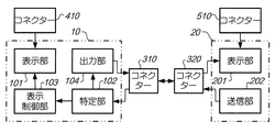
図1は、実施形態の表示システム1の外観を示す図である。表示システム1は、コマンダー(マスター)10と、スレーブ20と、通信線30とを備える。コマンダー10及びスレーブ20は、画像を投射して表示する投写型表示装置(いわゆるプロジェクター)である。通信線30は、両端にコネクター310及び320をそれぞれ有する。コネクター310はコマンダー10に接続され、コネクター320はスレーブ20に接続されている。このように、コマンダー10及びスレーブ20は、いずれも通信線30が接続されており、通信線30を介して互いに通信することができるようになっている。また、コマンダー10及びスレーブ20は、ケーブル40及び50をそれぞれ介してPC(Personal computer:パーソナルコンピュータ。ノート型でもタブレット型でもよい。)2と接続されている。ケーブル40は、一方の端部にコネクター410を有し、このコネクター410がコマンダー10に接続されている。また、ケーブル50は、一方の端部にコネクター510を有し、このコネクター510がスレーブ20に接続されている。なお、コマンダー10及びスレーブ20とPC2との接続は、ハブを介してもよいし、一方のプロジェクターを介して他方が接続されるいわゆるカスケード接続であってもよい。
Embodiment Hereinafter, an embodiment of the present invention will be described with reference to the drawings.
FIG. 1 is a diagram illustrating an appearance of a display system 1 according to the embodiment. The display system 1 includes a commander (master) 10, a
PC2は、画像を示すデータ(画像データという)を生成したり記憶したりする装置である。ここでいう画像とは、写真のような静止画像や、映画のような動画像(映像ともいう)を含むものである。PC2は、ケーブル40及び50を介してコマンダー10及びスレーブ20に画像データをそれぞれ送信する。コマンダー10及びスレーブ20は、PC2から送信されてくる画像データが示す画像をそれぞれスクリーン3に向けて投射する。以下では、スクリーン3において、コマンダー10が投射する画像が表示される領域のことを「第1画面」といい、スレーブ20が投射する画像が表示される領域のことを「第2画面」という。表示システム1においては、本システムを利用するユーザーによって、第1画面及び第2画面の外縁が合わせられるように調整されている。具体的には、第1画面及び第2画面の大きさや形状、これらの画面に表示される画像のフォーカスなどの設定が調整されている。以下では、第1画面及び第2画面が重なって形成されている領域のことを「表示領域」という。図1では、表示領域4が示されている。表示領域4には、コマンダー10及びスレーブ20からそれぞれ投射された画像が重畳して表示されている。
The PC 2 is a device that generates and stores data indicating an image (referred to as image data). The image referred to here includes a still image such as a photograph and a moving image (also referred to as a video) such as a movie. The PC 2 transmits image data to the
上記のように、複数台のプロジェクターが表示領域に画像を重畳させて表示することを、スタック表示という。スタック表示は、例えば、左目用の画像と右目用の画像とを重畳させることで3D画像を表示するという用途で用いられる。また、スタック表示は、他にも、1台のプロジェクターでは表示した画像の明るさが足りないときに、複数台のプロジェクターにより投射される光を足し合わせることで、より明るい画像を表示させるという用途でも用いられる。このように光を足し合わせる場合、PC2は、コマンダー10及びスレーブ20に対して、同じ画像を示す画像データを送信する。コマンダー10及びスレーブ20が各々に送信されて来た画像データが示す画像、すなわち同じ画像を表示領域4に表示することで、これらの画像が互いに重畳して表示される。表示システム1では、上記のとおり第1画面及び第2画面の外縁が合わせられているので、各画像が表している絵や文字が2重に重なったように見えることなく、これらの画像が1つの画像として表示される。
As described above, the display in which a plurality of projectors superimpose an image on the display area is referred to as stack display. Stack display is used, for example, for displaying a 3D image by superimposing a left-eye image and a right-eye image. In addition, stack display is used to display a brighter image by adding the light projected by multiple projectors when the brightness of the image displayed by one projector is insufficient. But also used. When adding light in this way, the PC 2 transmits image data indicating the same image to the
スタック表示が行われるときには、コマンダー10及びスレーブ20は、スタック表示モードで動作するようになっている。このスタック表示モードでは、例えば、コマンダー10は、スレーブ20に対して所定の動作を行うことを指示するコマンドを通信線30を介して送信する。一方、スレーブ20は、コマンダー10から送信されてくるコマンドに基づいて動作し、他の操作は受け付けないようになっている。
When the stack display is performed, the
図2は、コマンダー10のハードウェアの構成を示すブロック図である。コマンダー10は、制御部110と、記憶部120と、操作部130と、投射部140と、第1通信部150と、第2通信部160と、温度測定部170とを備える。制御部110は、CPU(Central Processing Unit)等の演算装置と、ROM(Read Only Memory)及びRAM(Random Access Memory)などの記憶装置とを有する。CPUは、RAMをワークエリアとして用いてROMや記憶部120に記憶されたプログラムを実行することによって、コマンダー10の各部の動作を制御する。記憶部120は、磁気的、光学的記録装置または半導体記憶素子を有し、制御プログラムを含む各種プログラム、及び、各種設定値等のデータを記憶する。操作部130は、制御部110に接続されている。操作部130は、各種スイッチ及びインジケーターランプを備え、コマンダー10の外装筐体(図示略)に配置されている操作パネルを備えてもよいし、いわゆるリモコン(リモートコントローラー)から赤外線信号を受光する受光部を備えてもよい。
FIG. 2 is a block diagram illustrating a hardware configuration of the
投射部140は、画像データが示す画像を投射して表示する表示手段である。詳細には、投射部140は、例えば、離間して配置される2本の電極を備えた放電ランプ及び画像データに応じて光を変調する液晶パネル(図示略)等を有する。放電ランプは、電圧が印加されると、2本の電極間で生じた放電により光を発し、その光を所定の方向に出射する。液晶パネルは、画像データに応じて駆動して、放電ランプが出射した光を、その画像データが示す画像を表すように変調する。投射部140は、液晶パネルが変調した光を投射して、その光が表す画像を例えば図1に示すスクリーン3に表示する。また、投射部140は、放電ランプが使用された時間(使用時間)を測定する測定手段を有する。この測定手段は、測定した使用時間を示すデータを制御部110に供給する。
The
第1通信部150は、コネクターを有し、このコネクターが通信線30のコネクター310と接続されている。第1通信部150は、このようにして接続されている通信線30を介してスレーブ20とデータを送信または受信する。第2通信部160は、コネクターを有し、このコネクターが図1に示すケーブル40のコネクター410と接続している。第2通信部160は、このようにして接続されているケーブル40を介してPC2から送信されてくる画像データを受信する。温度測定部170は、コマンダー10の内部の所定の場所(例えば放電ランプの周辺)の温度を測定する手段である。温度測定部170は、測定した温度を示すデータを制御部110に供給する。
The
図3は、スレーブ20のハードウェアの構成を示すブロック図である。スレーブ20は、コマンダー10と共通するハードウェアを備えている。すなわち、スレーブ20は、制御部210と、記憶部220と、操作部230と、投射部240と、第1通信部250と、第2通信部260と、温度測定部270とを備える。ただし、スレーブ20では、コマンダー10と違い、第1通信部250が有するコネクターが通信線30のコネクター320と接続され、第2通信部260が有するコネクターがケーブル50のコネクター510と接続されている。また、スレーブ20は、記憶部に記憶されているプログラムがコマンダー10と異なっており、これにより、コマンダー10とは異なる動作を行う。コマンダー10及びスレーブ20は、各々の制御部がプログラムを実行して各部を制御することで、以下に示す機能を実現する。
FIG. 3 is a block diagram illustrating a hardware configuration of the
図4は、コマンダー10及びスレーブ20が実現する機能を示すブロック図である。表示システム1においては、コマンダー10が第1投射型表示装置の一例であり、スレーブ20が第2投射型表示装置の一例である。コマンダー10は、表示部101と、特定部102と、表示制御部103と、出力部104とを備える。また、スレーブ20は、表示部201と、送信部202とを備える。
FIG. 4 is a block diagram illustrating functions realized by the
表示部101(第1表示手段及び表示手段の一例)は、図1に示すケーブル40のコネクター410と接続されており、ケーブル40を介してPC2から送信されてくる画像データが示す画像を投射して上述した第1画面に表示する手段である。表示部101は、図2に示す制御部110、投射部140及び第2通信部160が協働して実現する機能である。また、表示部201(第2表示手段の一例)は、ケーブル50のコネクター510と接続されており、ケーブル50を介してPC2から送信されてくる画像データが示す画像を投射して上述した第2画面に表示する手段である。また、表示部201は、通信線30のコネクター320と接続されており、コマンダー10から出力されてくる制御信号に基づき画像を表示する。表示部201は、図3に示す制御部210、投射部240、第1通信部250及び第2通信部260が協働して実現する機能である。
The display unit 101 (an example of the first display unit and the display unit) is connected to the
特定部102(特定手段の一例)は、自装置(コマンダー10)または他の投射型表示装置(スレーブ20)で発生した事象と、それらの事象が発生した投射型表示装置とを特定する手段である。特定部102が特定する事象とは、表示システム1を利用するユーザーに通知すべき事象として予め決められているものであり、以下では「要通知事象」という。表示システム1では、例えば、プロジェクターの内部の温度が閾値(温度閾値という)以上になるという事象(「温度超過」という。)や、放電ランプがプロジェクターに取り付けられてから使用された時間の累積値が閾値(時間閾値という)以上になるという事象(「ランプ使用時間超過」という。)などが要通知事象として決められている。
The specifying unit 102 (an example of specifying means) is a means for specifying an event that has occurred in its own device (commander 10) or another projection display device (slave 20) and a projection display device in which those events have occurred. is there. The event specified by the specifying
特定部102は、通信線30のコネクター310と接続されており、通信線30を介してスレーブ20からデータを取得できるようになっている。特定部102は、自装置またはスレーブ20から取得したデータに基づいて、そのデータの取得元である装置で発生した要通知事象を特定する。例えば、特定部102は、自装置の投射部140の測定手段が測定した結果(すなわち使用時間)を示すデータを取得し、取得したそのデータに基づいてランプ使用時間超過を特定する。また、特定部102は、自装置の温度測定部170が測定した結果(すなわち温度)を示すデータを取得して、取得したそのデータに基づいて温度超過を特定する。これらの場合、特定部102は、データの取得元である自装置、すなわちコマンダー10を、要通知事象が発生した投射型表示装置として特定する。
The specifying
また、特定部102は、スレーブ20から取得したデータに基づいて、そのデータの送信元の装置(すなわちスレーブ20)で発生した要通知事象を特定する。具体的には、特定部102は、取得したデータが要通知事象を示すものである場合に、そのデータが示す要通知事象を特定する。この場合、特定部102は、スレーブ20を、要通知事象が発生した投射型表示装置として特定する。特定部102は、投射部140の測定手段、温度測定部170及び第1通信部150の各部が動作している期間に、上記の特定を行う。この期間には、表示部101が画像を表示している期間のほかに、例えば、コマンダー10の電源は入っているためこれらの各部が動作しているが、表示部101による画像の表示はされていないという期間も含まれる。特定部102は、制御部110、投射部140、第1通信部150及び温度測定部170が協働して実現する機能である。特定部102は、特定した要通知事象及び投射型表示装置を示すデータを、表示制御部103及び出力部104に供給する。
In addition, the
送信部202(送信手段の一例)は、通信線30のコネクター320と接続されており、通信線30を介してコマンダー10にデータを送信できるようになっている。送信部202は、自装置(スレーブ20)において要通知事象が発生した場合に発生したその要通知事象を特定し、特定した要通知事象示すデータをコマンダー10に送信する手段である。送信部202は、投射部240の測定手段及び温度測定部270が測定した結果に基づき要通知事象を特定する。また、送信部202は、特定した要通知事象示すデータを、その要通知事象が発生したときに送信する。送信部202は、制御部210、投射部240、第1通信部250及び温度測定部270が協働して実現する機能である。
The transmission unit 202 (an example of a transmission unit) is connected to the
表示制御部103(制御手段の一例)は、特定部102により要通知事象及び装置が特定された場合に、表示部101を制御してOSD画像を表示させる手段である。ここにおいて、OSD画像とは、プロジェクターが記憶している画像データが示す画像のことである。OSD画像には、例えば、画像の明るさやコントラストを設定するための操作に用いられる画像などがある。表示制御部103は、表示部101を制御して、上述した第1画面の所定の領域にOSD画像を表示させる。この所定の領域のことを以下では「第1OSD画像領域」という。記憶部120には、第1画面上の各位置を表す座標系の座標を用いて第1OSD画像領域を表したデータが記憶されている。表示制御部103は、このデータに基づいて、OSD画像を第1OSD画像領域に表示させる。表示制御部103が表示させるOSD画像は、特定部102により特定された要通知事象及び装置に応じた画像を構成する第1OSD画像(第1構成画像の一例)及び第2OSD画像(第2構成画像の一例)のうちの第1OSD画像である。表示制御部103は、表示部101が画像を表示していない状態であれば、投射部140の放電ランプを点灯させて第1OSD画像を表示させる。表示制御部103は、制御部110、記憶部120及び投射部140が協働して実現する機能である。
The display control unit 103 (an example of a control unit) is a unit that controls the
出力部104(出力手段の一例)は、通信線30のコネクター310と接続されており、通信線30を介してスレーブ20にデータを出力できるようになっている。出力部104(出力手段の一例)は、特定部102により要通知事象及び装置が特定された場合に、スレーブ20に制御信号を出力する手段である。この制御信号は、上述した第1画面及び第2画面の外縁を合わせたときに、第2OSD画像が第1OSD画像領域と重なるようにその第2構成画像をスレーブ20に表示させる信号である。第2画面において、スレーブ20が第2構成画像を表示させる領域のことを、以下では「第2OSD画像領域」という。記憶部120には、第2画面上の各位置を表す座標系の座標を用いて第2OSD画像領域を表したデータが記憶されている。出力部104は、このデータに基づいて、第2OSD画像を第2OSD画像領域に表示させる制御信号を出力する。この制御信号を受信したスレーブ20は、第2画面の第2OSD画像領域に、第2構成画像を表示する。出力部104は、制御部110、記憶部120及び第1通信部150が協働して実現する機能である。表示制御部103及び出力部104が動作することで、コマンダー10は、表示部101に第1構成画像を表示させ、スレーブ20に第2構成画像を表示させるような制御を行う。
The output unit 104 (an example of output means) is connected to the
プロジェクターで要通知事象が発生すると、そのまま使用し続けたときに、電子回路が熱で壊れたり、寿命等の原因で放電ランプが光を発しなくなり、画像の表示が突然停止したりするといった異常が発生するおそれがある。表示システム1では、要通知事象を通知する処理を行うことで、これらの異常の発生を未然に防ぐようにユーザーに対して警告する。以下では、表示システム1が要通知事象をユーザーに通知する処理のことを「通知処理」という。 If a notification event occurs in the projector, the electronic circuit may break down due to heat, or the discharge lamp may not emit light due to the lifespan, etc. May occur. The display system 1 warns the user so as to prevent the occurrence of these abnormalities by performing a process of notifying a notification-necessary event. In the following, the process in which the display system 1 notifies the user of a notification required event is referred to as “notification process”.
図5は、通知処理においてコマンダー10及びスレーブ20が行う動作の一例を示すシーケンスチャートである。コマンダー10及びスレーブ20は、例えば、スタック表示モードとなるように設定されたタイミングや、スタック表示モードに設定された状態で起動したタイミングで、通知処理を開始する。まず、コマンダー10は、自装置またはスレーブ20で要通知事象が発生したか否かを判断する(ステップS10)。コマンダー10は、ステップS10でNOと判断した場合、ステップS10の処理を再び行う。つまり、コマンダー10は、ステップS10における判断がNOである間、すなわち要通知事象が発生したと判断するまでの間は、ステップS10の処理を所定の間隔(例えば1秒毎)で繰り返し実行する。
FIG. 5 is a sequence chart illustrating an example of operations performed by the
ステップS10の判断は、具体的には次のように行われる。コマンダー10は、例えば、温度測定部170が測定した温度が上記の温度閾値以上であった場合に、要通知事象が発生したことを判断する。また、コマンダー10は、投射部140が有する測定手段が測定した放電ランプの使用時間を記憶しておき、記憶しておいた使用時間の累積値が上記の時間閾値以上であった場合に、要通知事象が発生したことを判断する。スレーブ20は、自装置で要通知事象が発生したか否かを判断し(ステップS11)、この判断がNOである間、このステップS11の処理を所定の間隔(例えば1秒毎)で繰り返し実行する。スレーブ20は、自装置で要通知事象が発生したと判断した場合は(ステップS11:YES)、発生した要通知事象を示すデータをコマンダー10に送信する(ステップS12)。ステップS11及びS12は、図4に示すスレーブ20の送信部202により行われる動作である。一方、コマンダー10は、通信線30を介して送信されてきたデータが要通知事象を示すものであった場合に、要通知事象が発生したことを判断する。つまり、コマンダー10は、ステップS12において送信されてきたデータを受信した場合に、スレーブ20で要通知事象が発生したことを判断する。
Specifically, the determination in step S10 is performed as follows. For example, when the temperature measured by the
コマンダー10は、ステップS10でYESと判断した場合、発生した要通知事象と、その要通知事象が発生した装置とを特定する(ステップS13)。コマンダー10は、ステップS10において要通知事象の発生を判断したときに用いたデータの内容及び送り元に応じて、これらの要通知事象及び装置を特定する。コマンダー10は、例えば、ステップS10で用いたデータが温度測定部170から供給されたものであれば、要通知事象として温度超過を特定し、発生した装置として自装置を特定する。また、コマンダー10は、このデータが投射部140の測定手段から供給されたものであれば、要通知事象としてランプ使用時間超過を特定し、発生した装置として自装置を特定する。また、コマンダー10は、このデータがスレーブ20から送信されてきたものであれば、そのデータが示す要通知事象を特定し、発生した装置としてスレーブ20を特定する。コマンダー10は、ステップS10及びS12の動作を行うことで、自装置またはスレーブ20から取得したデータに基づいてそのデータの取得元の装置で発生した要通知事象及びそれが発生した装置を特定する。ステップS10及びS12は、図4に示す特定部102により行われる動作である。
When it is determined YES in step S10, the
続いて、コマンダー10は、上述した第2OSD画像を第2OSD画像領域に一定時間(例えば10秒間)表示させる制御信号をスレーブ20に出力する(ステップS14)。このステップS14は、図4に示す出力部104により行われる動作である。スレーブ20は、ステップS14においてコマンダー10から送信されてきた制御信号を受信すると、第2OSD画像領域に第2OSD画像を一定時間表示する(ステップS15)。そして、コマンダー10は、第1OSD画像領域に第1OSD画像を一定時間表示する(ステップS16)。このステップS16は、表示制御部103及び表示部101により行われる動作である。ステップS16における一定時間とは、第2OSD画像が表示される時間と同じ時間(例えば10秒間)である。コマンダー10は、ステップS14において制御信号を出力した時刻に応じた時刻に第1OSD画像を表示する。なお、コマンダー10は、ステップS16において第1画面に画像を表示していない状態であっても、投射部140の放電ランプを点灯して第1OSD画像を表示する。なお、なお、OSD画像の表示は、一定時間が経過したときに終了させる代わりに、操作部130を介してユーザーにより操作されたときに終了させてもよい。これは、以降に示すOSD画像についても同様である。以上の通知処理が行われることで、表示領域4には、第1OSD画像及び第2OSD画像が重なって表示される。
Subsequently, the
図6は、通知処理において表示される第1及び第2OSD画像の一例を示す図である。この例では、ステップS13において、コマンダー10でランプ消耗超過が発生したことが特定された場合に表示されるこれらのOSD画像を示している。図6(a)では、コマンダー10が表示する第1OSD画像A1が示され、図6(b)では、スレーブ20が表示する第2OSD画像A2が示されている。第1OSD画像A1は、長方形の画像A11と、「コマンダーでランプの寿命が近づいています。交換してください。」という文字列を表す画像A12とを有している。また、第2OSD画像A2は、長方形の画像A21と、「コマンダーでランプの寿命が近づいています。交換してください。」という文字列を表す画像A22とを有している。また、第1OSD画像A1及び第2OSD画像A2は、同じサイズの画像である。つまり、第1OSD画像A1及び第2OSD画像A2は、同一の画像である。
FIG. 6 is a diagram illustrating an example of the first and second OSD images displayed in the notification process. In this example, these OSD images displayed when it is determined in step S13 that the
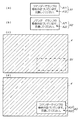
図6(c)では、これらのOSD画像が表示される前の図1に示す表示領域4における第1及び第2OSD画像領域が二点鎖線で示されている。この例では、第1及び第2OSD画像領域が一致しているため、この二点鎖線で示される領域をOSD画像領域B1という。図6(c)では、表示領域4に表示されている画像をハッチングをして示している。図6(d)では、図6(c)に示す表示領域4のOSD画像領域B1に、第1OSD画像A1及び第2OSD画像A2が投射された様子が示されている。このOSD画像領域B1には、互いに重なった第1OSD画像A1及び第2OSD画像A2により表されるOSD画像A3が表示されている。前述したとおり、第1OSD画像A1及び第2OSD画像は同一の画像である。このため、これらのOSD画像と同様に、OSD画像A3も、長方形の画像A31と、「コマンダーでランプの寿命が近づいています。交換してください。」という文字列を表す画像A32とを有する画像となっている。この文字列は、コマンダーでランプ使用時間超過が発生したことを表している。つまり、OSD画像A3は、ステップS13において特定された要通知事象及び装置に応じた画像となっている。ここにおいて、要通知事象及び装置に応じた画像とは、要通知事象及び装置そのものや、その要通知事象に対応してユーザが行うべき行動、その行動を行うためにユーザが知っておくべき情報などを、文字列や記号、絵などで表した画像のことである。
In FIG. 6C, the first and second OSD image areas in the
コマンダー10は、OSD画像を表示する場合に、第1画面に他の画像を表示しているときには、その画像の上にOSD画像を重ねて表示する。このとき、コマンダー10は、OSD画像を表示する領域では、そこに表示していた画像を投射しないようにする。これにより、OSD画像は、先に表示されていた画像と入り交じることなく表示される。スレーブ20も、コマンダー10と同様にOSD画像を表示する。しかし、スタック表示がされているときに、仮に、一方のプロジェクターがOSD画像を表示して、他方のプロジェクターが画像をそのまま表示し続けていると、その画像がOSD画像と入り交じってしまう。その結果、1台で表示するときのようにOSD画像が他の画像と入り交じらない場合に比べて、OSD画像が表す内容がユーザーに伝わりにくくなる。表示システム1では、コマンダー10及びスレーブ20がスタック表示をする場合に、これらのプロジェクターの両方が、各OSD画像(第1OSD画像A1及び第2OSD画像A2)を同一の領域(OSD画像領域B1)に表示する。つまり、これらのOSD画像が互いに重なって表されているOSD画像A3も、先に表示されていた画像と入り交じることがない。このため、OSD画像A3が表す文字列は、他の画像と入り交じって見にくくなるということがない。従って、本実施形態によれば、これらの投射型表示装置(コマンダー10またはスレーブ20)で発生した要通知事象をユーザーに確実に伝えることができる。
When displaying the OSD image, the
また、第1及び第2OSD画像が同一の画像であるため、OSD画像A3が表す文字列は、第1及び第2OSD画像が表す文字列よりも明るくなっている。このため、コマンダー10は、1台のプロジェクターでOSD画像を表示させる場合よりも明るいOSD画像(この例ではOSD画像A3)を表示させることができる。
Further, since the first and second OSD images are the same image, the character string represented by the OSD image A3 is brighter than the character string represented by the first and second OSD images. Therefore, the
また、プロジェクターが特定した要通知事象及び装置を、リモート接続された管理用の装置に表示するようにして遠隔地にいる管理者に伝えるようにしたシステムが用いられる場合がある。その場合、通知された内容は管理者しか分からないため、管理者から連絡があるか、管理者が現地に行くかしないと、プロジェクターから通知された内容が表示システム1を利用しているユーザーに伝わらないことになる。ここでいう表示システム1を利用しているユーザーとは、表示領域4に表示されている画像を見ているユーザーのことである。本実施形態では、コマンダー10が自装置及びスレーブ20を制御することで、図6(d)に示すようなOSD画像A3が表示領域4に表示される。これにより、コマンダー10は、特定した要通知事象及び装置を、表示領域4を見ているユーザー、すなわち、表示システム1を利用しているユーザーに確実に通知することができる。この通知をされたユーザーは、その場で発生した要通知事象の内容及びどのプロジェクターでそれが発生したかということを把握することになる。このため、ユーザーは、発生した要通知事象に対応して何らかの処置を行うか、そのまま継続して使用するかという判断をその場で行うことができる。そして、ユーザーが何らかの処置を行った場合、そのまま使用し続けたときに生じる異常が発生することがなくなり、そのような異常が発生してプロジェクターが使用できなくなることもなくなる。このように、コマンダー10は、表示システム1の可用性を高める、すなわち、ユーザーにより利用される時間を増やすことできる。
Further, there is a case in which a notification event and device specified by a projector are displayed on a remotely connected management device so as to be transmitted to a remote manager. In that case, since only the administrator knows the notified content, the notification notified from the projector is not sent to the user who uses the display system 1 unless the administrator contacts or the administrator goes to the site. It will not be transmitted. The user who uses the display system 1 here is a user who is viewing an image displayed in the
[変形例]
上述した実施形態は、本発明の実施の一例に過ぎず、以下のように変形させてもよい。また、上述した実施形態及び以下に示す各変形例は、必要に応じて組み合わせて実施してもよい。
[Modification]
The above-described embodiment is merely an example of implementation of the present invention, and may be modified as follows. Moreover, you may implement combining embodiment mentioned above and each modification shown below as needed.
(変形例1)
コマンダー10は、上述した実施形態では、互いに同一の画像である第1OSD画像及び第2OSD画像が表示されるような制御を行ったが、これら以外のOSD画像が、第1OSD画像及び第2OSD画像として表示されるような制御を行ってもよい。コマンダー10は、要するに、互いに重なって表示されたときに、ステップS13において特定した要通知事象及び装置に応じた画像となるような第1OSD画像及び第2OSD画像を表示させればよい。
(Modification 1)
In the above-described embodiment, the
図7は、本変形例において表示されるOSD画像の一例を示す図である。図7(a)では、図6(a)に示されたものと同じ第1OSD画像A1が示されている。第1OSD画像A1は、実際には、黒色一色に塗りつぶされた長方形の画像A11と、白色の文字列を表した画像A12とを有している。図7(a)では、見やすくするために、画像A11を白抜きの長方形で、画像A12を黒色の文字で表している。図7(b)では、画像A11と同じサイズの長方形の画像である第2OSD画像A4が示されている。この第2OSD画像A4は、実際には、黒色一色に塗りつぶされた画像である。図7(b)では、見やすくするために、画像A4を白抜きの長方形で表している。 FIG. 7 is a diagram illustrating an example of an OSD image displayed in the present modification. In FIG. 7A, the same first OSD image A1 as that shown in FIG. 6A is shown. The first OSD image A1 actually includes a rectangular image A11 that is painted black and an image A12 that represents a white character string. In FIG. 7A, the image A11 is represented by a white rectangle and the image A12 is represented by a black character for easy viewing. FIG. 7B shows a second OSD image A4 that is a rectangular image having the same size as the image A11. The second OSD image A4 is actually an image that is painted black. In FIG. 7B, the image A4 is represented by a white rectangle for easy viewing.
図7(c)では、図6(c)に示す表示領域4のOSD画像領域B1に、第1OSD画像A1及び第2OSD画像A4が投射された様子が示されている。OSD画像領域B1には、互いに重なった第1OSD画像A1及び第2OSD画像A4により表されるOSD画像A5が表示されている。OSD画像A5は、長方形の画像A51と、「コマンダーでランプの寿命が近づいています。交換してください。」という文字列を表す画像A52とを有している。第2OSD画像A4は、前述したとおり、黒色一色に塗りつぶされた画像である。このため、OSD画像A5は、第1OSD画像A1と同じ画像がそのまま表されることになる。仮に、第2OSD画像A2の代わりに、白色一色に塗りつぶされた画像が投射されていると、この画像と画像A12が表す白色の文字列とが入り交じってしまい、この文字列の内容をユーザーが識別しにくくなる。本変形例に係るコマンダー10は、通知したい内容を表す文字列の画像A12を白色とし、その背景となる画像A11及びOSD画像A4を黒色とすることで、ユーザーがこれらの画像を識別することができるようにしている。
FIG. 7C shows a state in which the first OSD image A1 and the second OSD image A4 are projected on the OSD image area B1 of the
OSD画像領域B1に表示されるOSD画像は、ユーザーに通知する内容を表す部分(通知部分)とその背景となる部分(背景部分)とを有している。この通知部分とは、コマンダー10が図5に示すステップS13において特定した結果を示す画像のことである。コマンダー10は、この通知部分が背景部分に対して識別可能となるように、第1OSD画像及び第2OSD画像を表示させる。具体的には、コマンダー10は、通知部分と背景部分とのコントラストの値が、ユーザーが通知部分を識別できる程度の値になっているOSD画像を表示させる。図7に示したOSD画像はその一例である。この例では、コマンダー10は、第2OSD画像A4を単色(黒色)で表示させ、その単色以外の色(白色)で通知部分を表す第1OSD画像A1を表示している。この場合、第1OSD画像A1の中で、実際に通知部分を表しているのは画像A12であり、画像A11は、第2OSD画像A4とともに背景部分を表している。
The OSD image displayed in the OSD image area B1 has a portion (notification portion) representing the content notified to the user and a portion (background portion) serving as the background thereof. This notification part is an image showing the result specified by the
なお、コマンダー10は、例えば、第2OSD画像を単色ではなく複数の色で表示させてもよい。この場合、コマンダー10は、それらの色に対して識別可能な色で上記の通知部分を表す第1OSD画像を表示させる。また、コマンダー10は、第1OSD画像及び第2OSD画像が示す内容を反対にして表示させてもよい。要するに、コマンダー10は、第1OSD画像及び第2OSD画像のいずれか一方の画像を所定の色(単数または複数の色)で表示させ、且つ、その所定の色に対して識別可能な色で上記の通知部分を表す画像を他方の画像として表示させればよい。この場合、図4に示す表示制御部103は、第1OSD画像を所定の色で表示させ、または特定部102により特定された結果をその所定の色に対して識別可能な色で表す第1OSD画像を表示させる。出力部104は、表示制御部103が第1OSD画像を所定の色で表示させる場合には、特定部102により特定された結果をその所定の色に対して識別可能な色で表す第2OSD画像を表示させる制御信号を出力する。また、出力部104は、表示制御部103が第1OSD画像を前述した識別可能な色で表示させる場合には、第2OSD画像を上記所定の色で表示させる制御信号を出力する。
コマンダー10は、OSD画像領域B1にOSD画像を表示させた後に、このOSD画像が表している内容を変化させる場合がある。
Note that the
The
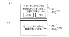
図8は、OSD画像領域B1に表示されるOSD画像の他の一例を示す図である。図8(a)ではOSD画像A6が示され、図8(b)では表示される内容が変化したOSD画像A6aが示されている。OSD画像A6は、画像A11と同様の長方形の画像A61と、「コマンダーでランプの寿命が近づいています。交換しますか?」、「YES」及び「NO」という文字列を表す画像A62とを有する。画像A62の「YES」及び「NO」という部分は、ユーザーの操作により選択できるようになっている。コマンダー10は、例えば「YES」という部分が選択されると、OSD画像A6aを表示させる。OSD画像A6aは、画像A61と、「それでコマンダーの電源を落とします。」文字列を表す画像A62aとを有する。コマンダー10は、OSD画像A6aを一定時間表示した後、自装置の電源を落とす動作を行う。
FIG. 8 is a diagram illustrating another example of the OSD image displayed in the OSD image area B1. FIG. 8A shows an OSD image A6, and FIG. 8B shows an OSD image A6a in which the displayed content is changed. The OSD image A6 includes a rectangular image A61 similar to the image A11, and an image A62 representing the character strings “YES in the commander. Are you going to replace it?”, “YES” and “NO” Have. The portions “YES” and “NO” of the image A62 can be selected by a user operation. For example, when the “YES” portion is selected, the
図8に示すようなOSD画像を表示させる場合に、図6で示したように同一の第1OSD画像及び第2OSD画像を表示させていると、コマンダー10は、それらのOSD画像の両方を同期させて変化させなければならない。これらのOSD画像の変化が同期できていない場合、一方のOSD画像が変化してから他方のOSD画像が変化するまでの期間は、異なる内容の画像が重なって入り交じることになる。このため、この期間には、ユーザーにとって見にくいOSD画像が表示されることになる。このような場合に、本変形例に係るコマンダー10は、図7(a)に示す第1OSD画像A1のように通知する内容を表している画像のみを変化させ、第2OSD画像A4のような単色の画像の方は変化させない。つまり、コマンダー10は、上記のような同期を行う必要がなく、言い換えれば、第1OSD画像及び第2OSD画像を同期させなくても、ユーザーにとって見やすい画像を表示することができる。
When the OSD image as shown in FIG. 8 is displayed, if the same first OSD image and second OSD image are displayed as shown in FIG. 6, the
(変形例2)
コマンダー10は、変形例1では、第1OSD画像及び第2OSD画像のうちの一方の画像を単色で表示させたが、これには限らない。要するに、OSD画像領域B1に重ねて投射された第1OSD画像及び第2OSD画像によって、図7(c)に示すOSD画像A5のような画像が表示されるようになっていればよい。
(Modification 2)
In the first modification, the
図9は、本変形例においてOSD画像領域B1に表示されるOSD画像の一例を示す図である。図9(a)では第1OSD画像A7が示され、図9(b)では第2OSD画像A8が示されている。第1OSD画像A7は、画像A11と同様の長方形の画像A71と、「コマンダー」とう文字列を表す画像A72とを有する。第2OSD画像A8は、画像A11と同様の長方形の画像A81と、「でランプの寿命が近づいています。交換してください。」とう文字列を表す画像A82とを有する。これらのOSD画像がOSD画像領域B1に投射されると、図7(c)に示すOSD画像A5が表示されることになる。この場合、画像A72及びA82が上述した通知部分となり、画像A71及びA81が背景部分となる。このように、本変形例に係るコマンダー10は、画像A72及びA82のような文字列を表す画像を組み合わせて表示させることで、ステップS13において特定された結果を表している。つまり、コマンダー10は、文字列を表す画像のうち、内容が共通する部分は1つの画像データを共有することができる。これにより、コマンダー10は、本変形例のように画像を組み合わせて表示させない場合に比べて、記憶部120に記憶させておく画像データの量を少なくすることができる。
FIG. 9 is a diagram showing an example of an OSD image displayed in the OSD image area B1 in the present modification. 9A shows the first OSD image A7, and FIG. 9B shows the second OSD image A8. The first OSD image A7 includes a rectangular image A71 similar to the image A11, and an image A72 representing a character string “commander”. The second OSD image A8 includes a rectangular image A81 similar to the image A11, and an image A82 representing a character string “The lamp life is approaching. Replace it.” When these OSD image is projected in the OSD image area B1, so that the OSD image A5 shown in FIG. 7 (c) is displayed. In this case, the image A72 and A82 become notification portion described above, the image A 71 and A 81 is a background portion. As described above, the
(変形例3)
コマンダー10は、上述した実施形態及び変形例では、第1OSD画像及び第2OSD画像を同じサイズで且つ全体が重なるように表示させたが、これには限らない。例えば、コマンダー10は、異なるサイズの第1及び第2OSD画像を表示させてもよいし、第1及び第2OSD画像の一部が重ならないようにして表示させてもよい
(Modification 3)
In the above-described embodiment and modification, the
図10は、本変形例における第1及び第2OSD画像の一例を示す図である。図10(a)では、図7に示す第1OSD画像A1と、第2OSD画像A4のサイズを大きくした第2OSD画像A9とが重ねて表示されている様子が示されている。この場合、第1OSD画像A1は、全体が第2OSD画像A9と重なるように表示されている。これにより、通知部分である画像A12は、第1及び第2OSD画像領域以外の領域に表示されている画像と入り交じらないようになっている。従って、画像A12が表す文字列は、他の画像と入り交じって見にくくなるということがない。 FIG. 10 is a diagram illustrating an example of the first and second OSD images in the present modification. FIG. 10A shows a state in which the first OSD image A1 shown in FIG. 7 and the second OSD image A9 in which the size of the second OSD image A4 is increased are displayed in an overlapping manner. In this case, the first OSD image A1 is displayed so as to overlap the second OSD image A9 as a whole. As a result, the image A12 which is a notification portion is not mixed with images displayed in areas other than the first and second OSD image areas. Therefore, the character string represented by the image A12 does not become difficult to see when mixed with other images.
図10(b)では、図9に示す第1OSD画像A7及び第2OSD画像A8が、図9に示す場合よりもずれて表示されている様子が示されている。図10(b)では、黒色の長方形の画像A71及びA81が重なった部分に、文字列を表す画像A72及びA82が表示されている。このため、通知部分である画像A72及びA82は、第1及び第2OSD画像領域以外の領域に表示されている画像と入り交じらないようになっている。この場合も、画像A72及びA82が表す文字列は、他の画像と入り交じって見にくくなるということがない。以上のとおり、要するに、コマンダー10は、第1及び第2OSD画像のうちの通知部分となる画像が、第1及び第2OSD画像領域以外の領域に表示されている画像と入り交じらないように、第1及び第2OSD画像を表示させればよい。
FIG. 10B shows a state where the first OSD image A7 and the second OSD image A8 shown in FIG. 9 are displayed with a shift from the case shown in FIG. In FIG. 10B, images A72 and A82 representing a character string are displayed in a portion where black rectangular images A71 and A81 overlap. For this reason, the images A72 and A82, which are notification parts, do not mix with images displayed in areas other than the first and second OSD image areas. Also in this case, the character string represented by the images A72 and A82 does not become difficult to see by mixing with other images. As described above, in short, the
(変形例4)
表示システム1は、上述した実施形態では、2台のプロジェクターを備えていたが、3台以上のプロジェクターを備えていてもよい。この場合も、スタック表示で用いられるコマンドを送信するプロジェクター、すなわちコマンダーは1台であり、残りのプロジェクターはいずれもスレーブとなる。この場合、各プロジェクターを通信線30を介して接続する方法は、3通りある。
(Modification 4)
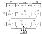
Although the display system 1 includes two projectors in the above-described embodiment, the display system 1 may include three or more projectors. Also in this case, there is one projector that transmits commands used for stack display, that is, a commander, and the remaining projectors are all slaves. In this case, there are three methods for connecting each projector via the
図11は、3台のプロジェクターを備える表示システムにおいて、各プロジェクターを接続する方法を示す図である。図11(a)では、コマンダー10、スレーブ20a及びスレーブ20bを、この順番に直列に接続した場合を示している。この場合、コマンダー10は、スレーブ20aを介してスレーブ20bにコマンドを送信する。スレーブ20bの図4に示す送信部は、スレーブ20aを介してデータをコマンダー10に送信する。図11(b)では、コマンダー10がスレーブ20a及び20bのそれぞれと1対1で接続されている場合を示している。図11(c)では、3台のプロジェクターが、いずれも中継器5を介して接続されている場合を示している。図11(b)及び(c)に示す場合では、スレーブ20a及び20bの送信部は、いずれも、直接コマンダー10にデータを送信する。
FIG. 11 is a diagram illustrating a method of connecting each projector in a display system including three projectors. FIG. 11A shows a case where the
(変形例5)
表示システムは、上述した実施形態では、スタック表示を行ったが、各画像を並べて表示するタイリングと呼ばれる方法で画像を表示(タイリング表示という)してもよい。この場合、コマンダー10は、スタック表示のときとは異なる方法で通知処理を行う。以下、図12を参照して、本変形例に係る通知処理について説明する。
(Modification 5)
In the embodiment described above, the display system performs stack display. However, the display system may display images (referred to as tiling display) by a method called tiling that displays images side by side. In this case, the
図12は、タイリング表示された表示領域4に表示されるOSD画像の一例を示す図である。図12では、上下方向の上向きを示す矢印B1と、左右方向の右向きを示す矢印B2とが示されている。この例では、4台のプロジェクターによって4つ画像が上下方向及び左右方向にそれぞれ2列ずつ並べて表示されている。図12に示す破線は、各画像の境界を示している。この例では、コマンダー10が左上の画像を表示し、3台のスレーブ20が残りの画像をそれぞれ表示しているものとする。コマンダー10は、4台のプロジェクターがそれぞれどの位置の画像を表示しているかということを示すデータを記憶部120に予め記憶しておく。そして、コマンダー10は、或るプロジェクターで要通知事象が発生したことを特定した場合、特定した結果に応じたOSD画像A10を表示させる。このとき、コマンダー10は、自装置も含む4つのプロジェクターのうちの1台に、OSD画像A10を表示させる。つまり、残りの3台は、OSD画像を表示させることなく、表示中の画像をそのまま表示し続ける。この例では、コマンダー10は、右下の画像を表示しているスレーブ20にOSD画像A10を表示させる。
FIG. 12 is a diagram illustrating an example of an OSD image displayed in the
また、コマンダー10は、OSD画像A10を、表示領域4の中央の領域C1よりも外側に表示させる。この領域C1は、例えば、上下方向における表示領域4の中心から端部までの中点と、左右方向における同様の中点とを通る、表示領域4と相似する長方形の領域である。コマンダー10は、領域C1を示すデータを予め記憶部120に記憶しておく。このデータは、例えば、各画像において領域C1の角の位置を示す座標のデータである。コマンダー10は、この例のようにOSD画像A10を右下の画像に表示させる場合であれば、領域C1の右下の角の位置を示す座標よりも左側且つ上側の領域(すなわち領域C1)よりも外側にOSD画像A10を表示させる。
Further, the
例えばプレゼンテーション資料や映画を表示する場合、表示領域4の中央に近い領域に表示される画像の方が、端に近い領域に表示される画像よりも、ユーザーが見たいものであることが多い。そのような場合に、コマンダー10は、ユーザーが見たい画像を隠すことが少ない位置にOSD画像を表示することができる。なお、図12に示す領域C1は一例であり、これよりも大きいまたは小さい領域であってもよい。また、この領域は、楕円形など長方形以外の形状であってもよい。要するに、この領域は、ユーザーがOSD画像を表示させたくない領域として予め決められた領域であればよく、表示領域4の中央を含む領域であることが望ましい。
For example, when displaying presentation materials or movies, the image displayed in the area closer to the center of the
(変形例6)
コマンダー10は、上述した実施形態では、OSD画像を、決められた位置(OSD画像領域B1など)に表示させたが、これ以外の位置に表示させてもよい。例えば、コマンダー10は、ユーザーの操作により設定された位置にOSD画像を表示させてもよいし、表示させたOSD画像をユーザーの操作により移動させるようにしてもよい。これにより、ユーザーが見たい場所の画像がOSD画像によって隠されることが少なくなる。
(Modification 6)
In the embodiment described above, the
通知処理によるOSD画像が表示される前に、画像の明るさやコントラストを設定するためのOSD画像が表示されている場合がある。また、通知処理によりOSD画像が表示されている期間に、他の要通知事象が発生して次のOSD画像が表示される場合がある。これらのような場合に、コマンダー10は、既に表示されているOSD画像と重ならない位置に、次のOSD画像を表示させるようにする。これにより、複数のOSD画像が重なって入り交じってしまい各OSD画像が表している内容をユーザーが理解しにくくなるということが、起きないようにすることができる。
Before the OSD image by the notification process is displayed, the OSD image for setting the brightness and contrast of the image may be displayed. In addition, during the period in which the OSD image is displayed by the notification process, another notification required event may occur and the next OSD image may be displayed. In such cases, the
(変形例7)
上述した実施形態では、スレーブ20が自装置で発生した要通知事象を特定し、スレーブ20から送信されてくるこの特定した要通知事象を示すデータを受信した場合に、コマンダー10が要通知事象の発生を判断した。表示システム1では、この特定をスレーブ20が行わず、コマンダー10が行うようにしてもよい。この場合、スレーブ20の投射部240の測定手段及び温度測定部270が測定した結果を示すデータを第1通信部250を介してコマンダー10に出力する。コマンダー10は、受信したこれらのデータが示す放電ランプの使用時間及び温度が、各々に対して定められた閾値以上であった場合に、スレーブ20で発生した要通知事象を特定する。
(Modification 7)
In the above-described embodiment, when the
本変形例によれば、スレーブ20の制御部210は、要通知事象を特定するという処理を行わなくてよくなり、処理の負担が軽減される。また、前述した各閾値は、コマンダー10だけが記憶しておけばよくなる。これにより、例えば、要通知事象の発生をより早く特定するようにこれらの閾値を変更するといった場合に、その変更の作業をコマンダー10にだけ行えばよくなり、ユーザーの手間が軽減される。なお、実施形態のように、スレーブ20が送信する要通知事象を示すデータのみでコマンダー10が要通知事象を特定する場合には、この特定を行うために送信されるデータは1つで済む。従って、その場合、放電ランプの使用時間や温度を示すデータのように他のデータをスレーブ20が送信してコマンダー10が要通知事象を特定する場合に比べて、コマンダー10とスレーブ20とが行う通信の負荷を少なくすることができる。
According to this modification, the
(変形例8)
コマンダー10は、上述した実施形態では、ステップS13においてどちらの装置で何の要通知事象が発生したかを特定したが、単に要通知事象が発生したことだけを特定してもよい。この場合、コマンダー10は、表示システム1が備えるいずれかのプロジェクターで要通知事象が発生したことを表すOSD画像を、OSD画像領域B1に表示させる。この場合でも、ユーザーは、表示されたOSD画像の内容から、表示システム1をそのまま利用し続けるか、利用を止めて何らかの対処を行うかを選択することができる。
(Modification 8)
In the above-described embodiment, the
(変形例9)
表示システムが備えるプロジェクターは、上述したスタック表示モードで動作するものには限らない。表示システムは、例えば、2台のプロジェクターを並べて、それぞれが画像を表示する画面の位置や形状等を調整して、同一の画像が重なって表示されるようにしたものであってもよい。この場合も、これらのプロジェクターは、通信線30により互いに接続され、図5のステップS12及びS14において互いにデータを送信し合う。
(Modification 9)
The projector included in the display system is not limited to one that operates in the above-described stack display mode. For example, the display system may be configured such that two projectors are arranged side by side, and the positions and shapes of the screens on which the images are displayed are adjusted so that the same images are displayed in an overlapping manner. Also in this case, these projectors are connected to each other by the
(変形例10)
本発明は、コマンダー10やスレーブ20のような投射型表示装置(プロジェクター)の他にも、これらの投射型表示装置を備える表示システムや、図5に示す通知処理のようなこれらの投射型表示装置が実施する処理を実現するための方法としても捉えられる。
(Modification 10)
In addition to the projection display devices (projectors) such as the
(変形例11)
コマンダー及びスレーブは、上述した実施形態や変形例では、通信線30で接続されて有線通信を行っていたが、無線通信を行うようになっていてもよい。これらのプロジェクターは、例えば、Bluetooth(登録商標)の規格に基づいて通信を行う手段を備えておき、それらの手段を介して無線通信を行う。
(Modification 11)
The commander and the slave are connected via the
1…表示システム、2…PC、3…スクリーン、4…表示領域、5…中継器、10…コマンダー(マスター)、20…スレーブ、30…通信線、310、320…コネクター、40、50…ケーブル、410、510…コネクター、110、210…制御部、120、220…記憶部、130、230…操作部、140、240…投射部、150、250…第1通信部、160、260…第2通信部、170、270…温度測定部、101…表示部、102…特定部、103…表示制御部、104…出力部、201…表示部、202…送信部
DESCRIPTION OF SYMBOLS 1 ... Display system, 2 ... PC, 3 ... Screen, 4 ... Display area, 5 ... Repeater, 10 ... Commander (master), 20 ... Slave, 30 ... Communication line, 310, 320 ... Connector, 40, 50 ... Cable , 410, 510 ... connector, 110, 210 ... control unit, 120, 220 ... storage unit, 130, 230 ... operation unit, 140, 240 ... projection unit, 150, 250 ... first communication unit, 160, 260 ...
Claims (5)
第2画面に画像を投射して表示する他の投射型表示装置または自装置から取得したデータに基づいて当該データの取得元の装置で発生した事象を特定する特定手段と、
前記特定手段が前記事象を特定した場合に、前記第1表示手段を制御して、前記第1画面内の所定の領域に、当該特定された事象に応じた事象画像の一部を有する第1構成画像及び当該一部とは異なる前記事象画像の一部を有する第2構成画像のうちの当該第1構成画像を表示させる制御手段と、
前記第1画面及び前記第2画面の外縁を合わせたときに、前記第2構成画像が前記所定の領域と重なり且つ前記第1構成画像が有する前記事象画像の一部と当該第2構成画像が有する前記事象画像の一部とが重ならないように当該第2構成画像を前記他の投射型表示装置に表示させる制御信号を、前記特定手段が前記事象を特定した場合に出力する出力手段と
を備えることを特徴とする投射型表示装置。 First display means for projecting and displaying an image on the first screen;
A specifying means for specifying an event that has occurred in the device from which the data is acquired based on data acquired from another projection display device or the device itself that projects and displays an image on the second screen;
When the specifying unit specifies the event, the first display unit is controlled to include a part of an event image corresponding to the specified event in a predetermined area in the first screen. Control means for displaying the first constituent image of the second constituent image having a part of the event image different from the one constituent image and the part ;
When the combined outer edge of the first screen and the second screen, a portion said second said event image the second constituent image is included in the predetermined region and the heavy Do Ri and the first constituent image A control signal for displaying the second component image on the other projection display device so that the event image included in the component image does not overlap a part of the event image is output when the specifying unit specifies the event And a projection type display device.
前記制御手段は、当該特定手段により特定された事象及び投射型表示装置に応じた画像を構成する前記第1構成画像を前記第1表示手段に表示させ、
前記出力手段は、前記特定手段により特定された事象及び投射型表示装置に応じた画像を構成する第2構成画像を前記他の投射型表示装置に表示させる制御信号を出力する
ことを特徴とする請求項1に記載の投射型表示装置。 The specifying means specifies the projection display device in which the event has occurred, in addition to the event that has occurred,
The control means causes the first display means to display the first constituent image that constitutes an image corresponding to the event specified by the specifying means and the projection display device,
The output means outputs a control signal for causing the other projection type display device to display a second component image constituting an image corresponding to the event specified by the specifying means and the projection type display device. The projection display device according to claim 1.
前記特定手段は、前記他の投写型表示装置から受信した前記データによって示される事象を、当該他の投写型表示装置で発生した事象として特定する
ことを特徴とする請求項1又は2に記載の投射型表示装置。 The other projection display device, when an event occurs in the other projection display device, transmits data indicating the event to the own device,
The specifying means, according to the event indicated by the data received from the other projection display apparatus, in claim 1 or 2, characterized in that identifying the events occurring in the other of the projection display device Projection display device.
画像を投射して表示する第2表示手段と、自装置において事象が発生した場合に当該事象を示すデータを前記第1投写型表示装置に送信する送信手段とを備える第2投射型表示装置と
を具備することを特徴とする表示システム。 A first projection display device which is the projection display device according to claim 3 ;
A second projection type display device comprising: a second display unit for projecting and displaying an image; and a transmission unit for transmitting data indicating the event to the first projection type display unit when an event occurs in the device. A display system comprising:
前記第1投射型表示装置が、前記特定ステップにおいて前記事象が特定された場合に、前記表示手段を制御して、前記第1画面内の所定の領域に、当該特定された事象に応じた事象画像の一部を有する第1構成画像及び当該一部とは異なる前記事象画像の一部を有する第2構成画像のうちの当該第1構成画像を表示させる制御ステップと、
前記第1投射型表示装置が、前記第1画面及び前記第2画面の外縁を合わせたとき、前記第2構成画像が前記所定の領域と重なり且つ前記第1構成画像が有する前記事象画像の一部と当該第2構成画像が有する前記事象画像の一部とが重ならないように当該第2構成画像を前記第2投射型表示装置に表示させる制御信号を、前記場合に出力する出力ステップと
を備えることを特徴とする表示方法。 Based on data acquired from the first projection display device that includes a display unit that projects and displays an image on the first screen, or the second projection display device that projects and displays the image on the second screen. A specific step of identifying an event that has occurred in the device from which the data was obtained;
When the first projection type display device specifies the event in the specifying step, the first projection display device controls the display means to respond to the specified event in the predetermined area in the first screen. a control step for the display of the first constituent image of the second component image having a portion of said different event images from the first constituent image and some relevant with part of the event image,
Said event the first projection display apparatus, when the combined outer edge of the first screen and the second screen, the second constituent image is the predetermined region and the heavy Do Ri and the first constituent image with In this case, a control signal for displaying the second component image on the second projection display device is output so that a part of the image does not overlap a part of the event image included in the second component image. A display method comprising: an output step.
Priority Applications (3)
| Application Number | Priority Date | Filing Date | Title |
|---|---|---|---|
| JP2012075873A JP6094046B2 (en) | 2012-03-29 | 2012-03-29 | Projection type display device, display system, and display method |
| US13/746,922 US9004694B2 (en) | 2012-03-29 | 2013-01-22 | Projection type display device used with another projection type display device for projecting overlapping images, display system, and display |
| CN201310103680.5A CN103369280B (en) | 2012-03-29 | 2013-03-28 | Projection type image display apparatus, display system and display methods |
Applications Claiming Priority (1)
| Application Number | Priority Date | Filing Date | Title |
|---|---|---|---|
| JP2012075873A JP6094046B2 (en) | 2012-03-29 | 2012-03-29 | Projection type display device, display system, and display method |
Publications (3)
| Publication Number | Publication Date |
|---|---|
| JP2013205687A JP2013205687A (en) | 2013-10-07 |
| JP2013205687A5 JP2013205687A5 (en) | 2015-01-29 |
| JP6094046B2 true JP6094046B2 (en) | 2017-03-15 |
Family
ID=49234575
Family Applications (1)
| Application Number | Title | Priority Date | Filing Date |
|---|---|---|---|
| JP2012075873A Expired - Fee Related JP6094046B2 (en) | 2012-03-29 | 2012-03-29 | Projection type display device, display system, and display method |
Country Status (3)
| Country | Link |
|---|---|
| US (1) | US9004694B2 (en) |
| JP (1) | JP6094046B2 (en) |
| CN (1) | CN103369280B (en) |
Families Citing this family (7)
| Publication number | Priority date | Publication date | Assignee | Title |
|---|---|---|---|---|
| JP6181931B2 (en) * | 2013-01-28 | 2017-08-16 | キヤノン株式会社 | Projection apparatus, control method, program, and projection system |
| US9052577B2 (en) * | 2013-03-14 | 2015-06-09 | Flytech Technology Co., Ltd. | Display device having a double image display function |
| JP2015152617A (en) * | 2014-02-10 | 2015-08-24 | 株式会社リコー | Image projection device, image projection system, and control method of image projection device |
| JP6370070B2 (en) * | 2014-03-19 | 2018-08-08 | キヤノン株式会社 | Display device |
| CN104184979B (en) * | 2014-08-01 | 2017-07-25 | 苏州佳世达光电有限公司 | The display methods and projection arrangement of a kind of on-screen menu |
| KR20170070415A (en) * | 2015-12-14 | 2017-06-22 | 현대자동차주식회사 | Image projectiing apparatus and control method thereof |
| JP2020046840A (en) * | 2018-09-18 | 2020-03-26 | キヤノン株式会社 | Image processing device, information processing method and program |
Family Cites Families (11)
| Publication number | Priority date | Publication date | Assignee | Title |
|---|---|---|---|---|
| US6545685B1 (en) * | 1999-01-14 | 2003-04-08 | Silicon Graphics, Inc. | Method and system for efficient edge blending in high fidelity multichannel computer graphics displays |
| JP3826659B2 (en) * | 2000-03-27 | 2006-09-27 | セイコーエプソン株式会社 | Projection display system and projection display device |
| JP2002287242A (en) | 2001-01-19 | 2002-10-03 | Mitsubishi Electric Corp | Projector, network system, and centralized management method for projector |
| JP2003152375A (en) | 2001-11-16 | 2003-05-23 | Sanyo Electric Co Ltd | Display and liquid crystal projector |
| JP2004013632A (en) | 2002-06-07 | 2004-01-15 | Canon Inc | Electronic conference system and computer-readable storage medium |
| JP2005094186A (en) * | 2003-09-16 | 2005-04-07 | Sharp Corp | D/a converter and data transmission method for use therein |
| JP4661161B2 (en) * | 2004-10-20 | 2011-03-30 | カシオ計算機株式会社 | Projection apparatus, projection method, and program |
| KR20060132125A (en) | 2005-06-17 | 2006-12-21 | 씨제이파워캐스트(주) | An advertisement system based on the digital media and method thereof |
| CN101527865B (en) * | 2009-01-05 | 2010-09-01 | 清华大学 | Projection type high-resolution multi-view auto-stereo display system |
| JP5570300B2 (en) * | 2010-05-26 | 2014-08-13 | キヤノン株式会社 | Projection apparatus and program |
| JP2012019442A (en) * | 2010-07-09 | 2012-01-26 | Hitachi Consumer Electronics Co Ltd | Projector system and projector |
-
2012
- 2012-03-29 JP JP2012075873A patent/JP6094046B2/en not_active Expired - Fee Related
-
2013
- 2013-01-22 US US13/746,922 patent/US9004694B2/en active Active
- 2013-03-28 CN CN201310103680.5A patent/CN103369280B/en active Active
Also Published As
| Publication number | Publication date |
|---|---|
| CN103369280B (en) | 2017-11-17 |
| JP2013205687A (en) | 2013-10-07 |
| US9004694B2 (en) | 2015-04-14 |
| US20130258289A1 (en) | 2013-10-03 |
| CN103369280A (en) | 2013-10-23 |
Similar Documents
| Publication | Publication Date | Title |
|---|---|---|
| JP6094046B2 (en) | Projection type display device, display system, and display method | |
| JP6088127B2 (en) | Display device, display device control method, and program | |
| US10574949B2 (en) | Projection apparatus for multi-projection, communication apparatus, control methods thereof, storage medium, and projection system | |
| JP2013097177A (en) | Display device, control method of display device, and program | |
| CN110018778B (en) | Communication apparatus, display apparatus, control method thereof, storage medium, and display system | |
| US9760332B2 (en) | Projection type display device, display system, and display method | |
| US10416813B2 (en) | Display system, display device, information processing device, and information processing method | |
| JP2008089886A (en) | Wireless transmission method | |
| JP2013205687A5 (en) | ||
| US11276372B2 (en) | Method of operation of display device and display device | |
| JP2014186087A (en) | Projector system, projector, and control method of projector system | |
| JP6024404B2 (en) | Information processing apparatus, projector, and control method for information processing apparatus | |
| JP2013029642A (en) | Image display device and control method of the same | |
| JP2016008999A (en) | Projector and control method of projector | |
| JP6369082B2 (en) | Projector, display device, and projector control method | |
| JP2014115363A (en) | Image display device, and control method of image display device | |
| US10942698B2 (en) | Control method of display system, display system, and display device | |
| JP2019036055A (en) | Controlled device, control method of the same, program and storage medium | |
| JP6760307B2 (en) | Display device | |
| JP2013061515A (en) | Projector, projector system, and control method for projector | |
| JP6212712B2 (en) | Video display device and video display system | |
| JP2013171235A (en) | Image display device, and control method of image display device | |
| JP6398256B2 (en) | Display device and notification method | |
| JP2015052630A (en) | Support device of projector, projector system, and control method of projector system | |
| JP2017181539A (en) | Display device and method of controlling the same |
Legal Events
| Date | Code | Title | Description |
|---|---|---|---|
| A521 | Request for written amendment filed |
Free format text: JAPANESE INTERMEDIATE CODE: A523 Effective date: 20141208 |
|
| A621 | Written request for application examination |
Free format text: JAPANESE INTERMEDIATE CODE: A621 Effective date: 20141208 |
|
| A977 | Report on retrieval |
Free format text: JAPANESE INTERMEDIATE CODE: A971007 Effective date: 20151014 |
|
| A131 | Notification of reasons for refusal |
Free format text: JAPANESE INTERMEDIATE CODE: A131 Effective date: 20151027 |
|
| A521 | Request for written amendment filed |
Free format text: JAPANESE INTERMEDIATE CODE: A523 Effective date: 20151218 |
|
| A131 | Notification of reasons for refusal |
Free format text: JAPANESE INTERMEDIATE CODE: A131 Effective date: 20160705 |
|
| TRDD | Decision of grant or rejection written | ||
| A01 | Written decision to grant a patent or to grant a registration (utility model) |
Free format text: JAPANESE INTERMEDIATE CODE: A01 Effective date: 20170117 |
|
| A61 | First payment of annual fees (during grant procedure) |
Free format text: JAPANESE INTERMEDIATE CODE: A61 Effective date: 20170130 |
|
| R150 | Certificate of patent or registration of utility model |
Ref document number: 6094046 Country of ref document: JP Free format text: JAPANESE INTERMEDIATE CODE: R150 |
|
| LAPS | Cancellation because of no payment of annual fees |