JP6093445B2 - Device for packing a dose of medicament and method for operating said device - Google Patents
Device for packing a dose of medicament and method for operating said device Download PDFInfo
- Publication number
- JP6093445B2 JP6093445B2 JP2015528952A JP2015528952A JP6093445B2 JP 6093445 B2 JP6093445 B2 JP 6093445B2 JP 2015528952 A JP2015528952 A JP 2015528952A JP 2015528952 A JP2015528952 A JP 2015528952A JP 6093445 B2 JP6093445 B2 JP 6093445B2
- Authority
- JP
- Japan
- Prior art keywords
- dose
- collection
- identifier
- collecting
- installation
- Prior art date
- Legal status (The legal status is an assumption and is not a legal conclusion. Google has not performed a legal analysis and makes no representation as to the accuracy of the status listed.)
- Active
Links
- 239000003814 drug Substances 0.000 title claims description 105
- 238000000034 method Methods 0.000 title claims description 24
- 238000012856 packing Methods 0.000 title 1
- 238000009434 installation Methods 0.000 claims description 104
- 229940079593 drug Drugs 0.000 claims description 95
- 239000007787 solid Substances 0.000 claims description 89
- 238000004806 packaging method and process Methods 0.000 claims description 48
- 238000013507 mapping Methods 0.000 claims description 26
- 238000004140 cleaning Methods 0.000 claims description 18
- 238000011109 contamination Methods 0.000 claims description 15
- 239000000126 substance Substances 0.000 claims description 13
- 239000003550 marker Substances 0.000 claims description 8
- 229940126589 solid medicine Drugs 0.000 claims description 3
- 239000011888 foil Substances 0.000 description 13
- 238000012423 maintenance Methods 0.000 description 13
- 239000006187 pill Substances 0.000 description 9
- 238000010438 heat treatment Methods 0.000 description 5
- 230000003287 optical effect Effects 0.000 description 3
- 230000008569 process Effects 0.000 description 3
- 230000003213 activating effect Effects 0.000 description 2
- 238000007599 discharging Methods 0.000 description 2
- 239000000463 material Substances 0.000 description 2
- 239000011159 matrix material Substances 0.000 description 2
- 239000004033 plastic Substances 0.000 description 2
- 239000004677 Nylon Substances 0.000 description 1
- 239000004809 Teflon Substances 0.000 description 1
- 229920006362 Teflon® Polymers 0.000 description 1
- 230000004888 barrier function Effects 0.000 description 1
- 238000005452 bending Methods 0.000 description 1
- 230000008901 benefit Effects 0.000 description 1
- 239000002775 capsule Substances 0.000 description 1
- 239000011248 coating agent Substances 0.000 description 1
- 238000000576 coating method Methods 0.000 description 1
- 230000006835 compression Effects 0.000 description 1
- 238000007906 compression Methods 0.000 description 1
- 230000001419 dependent effect Effects 0.000 description 1
- 238000001514 detection method Methods 0.000 description 1
- 230000006870 function Effects 0.000 description 1
- 230000007246 mechanism Effects 0.000 description 1
- 229920001778 nylon Polymers 0.000 description 1
- 239000003826 tablet Substances 0.000 description 1
- 239000012780 transparent material Substances 0.000 description 1
Images


Classifications
-
- B—PERFORMING OPERATIONS; TRANSPORTING
- B65—CONVEYING; PACKING; STORING; HANDLING THIN OR FILAMENTARY MATERIAL
- B65B—MACHINES, APPARATUS OR DEVICES FOR, OR METHODS OF, PACKAGING ARTICLES OR MATERIALS; UNPACKING
- B65B37/00—Supplying or feeding fluent-solid, plastic, or liquid material, or loose masses of small articles, to be packaged
- B65B37/005—Supplying or feeding fluent-solid, plastic, or liquid material, or loose masses of small articles, to be packaged by endless belts or chains
-
- B—PERFORMING OPERATIONS; TRANSPORTING
- B65—CONVEYING; PACKING; STORING; HANDLING THIN OR FILAMENTARY MATERIAL
- B65B—MACHINES, APPARATUS OR DEVICES FOR, OR METHODS OF, PACKAGING ARTICLES OR MATERIALS; UNPACKING
- B65B5/00—Packaging individual articles in containers or receptacles, e.g. bags, sacks, boxes, cartons, cans, jars
- B65B5/10—Filling containers or receptacles progressively or in stages by introducing successive articles, or layers of articles
- B65B5/101—Filling containers or receptacles progressively or in stages by introducing successive articles, or layers of articles by gravity
- B65B5/103—Filling containers or receptacles progressively or in stages by introducing successive articles, or layers of articles by gravity for packaging pills or tablets
-
- B—PERFORMING OPERATIONS; TRANSPORTING
- B65—CONVEYING; PACKING; STORING; HANDLING THIN OR FILAMENTARY MATERIAL
- B65B—MACHINES, APPARATUS OR DEVICES FOR, OR METHODS OF, PACKAGING ARTICLES OR MATERIALS; UNPACKING
- B65B37/00—Supplying or feeding fluent-solid, plastic, or liquid material, or loose masses of small articles, to be packaged
- B65B37/02—Supplying or feeding fluent-solid, plastic, or liquid material, or loose masses of small articles, to be packaged by gravity flow
-
- B—PERFORMING OPERATIONS; TRANSPORTING
- B65—CONVEYING; PACKING; STORING; HANDLING THIN OR FILAMENTARY MATERIAL
- B65G—TRANSPORT OR STORAGE DEVICES, e.g. CONVEYORS FOR LOADING OR TIPPING, SHOP CONVEYOR SYSTEMS OR PNEUMATIC TUBE CONVEYORS
- B65G17/00—Conveyors having an endless traction element, e.g. a chain, transmitting movement to a continuous or substantially-continuous load-carrying surface or to a series of individual load-carriers; Endless-chain conveyors in which the chains form the load-carrying surface
- B65G17/12—Conveyors having an endless traction element, e.g. a chain, transmitting movement to a continuous or substantially-continuous load-carrying surface or to a series of individual load-carriers; Endless-chain conveyors in which the chains form the load-carrying surface comprising a series of individual load-carriers fixed, or normally fixed, relative to traction element
-
- B—PERFORMING OPERATIONS; TRANSPORTING
- B65—CONVEYING; PACKING; STORING; HANDLING THIN OR FILAMENTARY MATERIAL
- B65G—TRANSPORT OR STORAGE DEVICES, e.g. CONVEYORS FOR LOADING OR TIPPING, SHOP CONVEYOR SYSTEMS OR PNEUMATIC TUBE CONVEYORS
- B65G37/00—Combinations of mechanical conveyors of the same kind, or of different kinds, of interest apart from their application in particular machines or use in particular manufacturing processes
-
- B—PERFORMING OPERATIONS; TRANSPORTING
- B65—CONVEYING; PACKING; STORING; HANDLING THIN OR FILAMENTARY MATERIAL
- B65G—TRANSPORT OR STORAGE DEVICES, e.g. CONVEYORS FOR LOADING OR TIPPING, SHOP CONVEYOR SYSTEMS OR PNEUMATIC TUBE CONVEYORS
- B65G43/00—Control devices, e.g. for safety, warning or fault-correcting
-
- B—PERFORMING OPERATIONS; TRANSPORTING
- B65—CONVEYING; PACKING; STORING; HANDLING THIN OR FILAMENTARY MATERIAL
- B65G—TRANSPORT OR STORAGE DEVICES, e.g. CONVEYORS FOR LOADING OR TIPPING, SHOP CONVEYOR SYSTEMS OR PNEUMATIC TUBE CONVEYORS
- B65G45/00—Lubricating, cleaning, or clearing devices
- B65G45/10—Cleaning devices
-
- G—PHYSICS
- G07—CHECKING-DEVICES
- G07F—COIN-FREED OR LIKE APPARATUS
- G07F11/00—Coin-freed apparatus for dispensing, or the like, discrete articles
- G07F11/02—Coin-freed apparatus for dispensing, or the like, discrete articles from non-movable magazines
- G07F11/04—Coin-freed apparatus for dispensing, or the like, discrete articles from non-movable magazines in which magazines the articles are stored one vertically above the other
- G07F11/16—Delivery means
- G07F11/26—Endless bands
-
- G—PHYSICS
- G07—CHECKING-DEVICES
- G07F—COIN-FREED OR LIKE APPARATUS
- G07F17/00—Coin-freed apparatus for hiring articles; Coin-freed facilities or services
- G07F17/0092—Coin-freed apparatus for hiring articles; Coin-freed facilities or services for assembling and dispensing of pharmaceutical articles
Description
本発明は、1用量の固形薬品ポーションを包装するための装置及び上記装置を動作させる方法に関する。 The present invention relates to an apparatus for packaging a dose of solid drug portion and a method of operating the apparatus.
錠剤、カプセル、丸薬等の1用量の固形薬品ポーションを、薬袋、パウチ又は他のタイプの包装の形態に包装すると有利であり、各薬袋内の固形薬品ポーションは経口摂取量毎に包装される。薬袋には、この薬剤を摂取するべき日及び時刻等のユーザ用情報が記載される。1人の特定のユーザ用の薬袋は通常互いにつながっており、ディスペンサボックス内で巻かれた状態で提供される。 It is advantageous to package a dose of solid drug portion such as tablets, capsules, pills, etc. in the form of a drug bag, pouch or other type of package, with the solid drug portion in each drug bag being packaged for each oral intake. The medicine bag describes information for the user such as the date and time when the medicine should be taken. One particular user's medicine bag is usually connected to each other and is provided in a rolled state in a dispenser box.
各薬包への1用量の固形薬品ポーション(バッチ)の充填は、ますます自動化されている。個々の薬包への最終的な包装のために、固形薬品ポーションを1用量に分割するための公知の装置は、それぞれ異なる種類の薬剤を備える複数の供給コンテナを備える。薬剤の処方箋を読むか又は入力した後、この処方箋に関係する供給コンテナを開いて、供給手段の下に位置決めされた中央落下ダクトに、そして更に漏斗に、1用量の固形薬品ポーションを降下させることができる。選択的に放出された固形薬品ポーションは漏斗の底部において薬袋等の包装内に受承され、その後この包装は閉鎖される。ここではユーザ用情報を有する包装の提供は、包装の充填前又は後に実現できる。特許文献1に記載の、1用量の固形薬品ポーションを包装するための公知の装置は、複数の貯蔵コンテナ(駆動用基部及びコンテナを備える錠剤ケースとも呼ばれる)を備え、各貯蔵コンテナは、複数の固形薬品ポーションを貯蔵し、1用量の固形薬品ポーションを吐出するための用量分割手段を(駆動機部に)有する。貯蔵コンテナを含む上記装置の上側セクションの下には、2つの収集容器が形成される(シャッタと呼ばれる)。各シャッタは、貯蔵コンテナのうちの半分から固形薬品ポーションを受承し、この薬品ポーションをホッパへ送り出し、このホッパは薬品ポーションを包装ステーションへと通過させる。貯蔵コンテナの2つの棚板の間の間隙によって形成される垂直なシュートは、貯蔵コンテナの用量分割手段が吐出した固形薬品ポーションを、2つの収集容器のうちの一方へと案内する。 The filling of one dose of solid drug portion (batch) into each medicine pack is increasingly automated. A known device for dividing a solid drug portion into a single dose for final packaging into individual drug packages comprises a plurality of supply containers, each with a different kind of drug. After reading or entering the drug prescription, open the supply container associated with this prescription and lower a dose of solid drug portion into the central drop duct positioned under the supply means and further into the funnel Can do. The selectively released solid drug portion is received in a package such as a medicine bag at the bottom of the funnel, after which the package is closed. Here, provision of a package having information for a user can be realized before or after filling the package. A known device for packaging a dose of solid drug portion described in Patent Document 1 comprises a plurality of storage containers (also referred to as a tablet case comprising a drive base and a container), each storage container comprising a plurality of storage containers. It has a dose dividing means (in the drive section) for storing the solid drug portion and discharging one dose of the solid drug portion. Under the upper section of the device containing the storage container, two collection containers are formed (called shutters). Each shutter receives a solid chemical portion from half of the storage container and delivers the chemical portion to a hopper which passes the chemical portion to the packaging station. A vertical chute formed by the gap between the two shelves of the storage container guides the solid drug portion discharged by the storage container's dose dividing means into one of the two collection containers.
しかしながら、この公知の装置は複数の欠点を有する。この公知の装置の重大な欠点は、装置の充填頻度が、垂直なシュートにおける吐出された固形薬品ポーションの(最長)降下時間に大きく左右され、またこれによって制限されることであり、従って公知の装置の充填頻度は制限されており、上昇させることはできない。しかしながら、薬剤の需要は常に増大しているため、現実的に、1用量の固形薬品ポーションの薬包を単位時間に対してより多く提供する必要がある。 However, this known device has several drawbacks. A significant disadvantage of this known device is that the filling frequency of the device is largely dependent on and limited by the (longest) drop time of the discharged solid chemical portion in the vertical chute and is therefore known. The filling frequency of the device is limited and cannot be raised. However, since the demand for drugs is constantly increasing, it is practically necessary to provide more medicine packages of one dose of solid drug portion per unit time.
オランダの特許文献1は、1用量の固形薬品ポーションを包装するための装置を開示している。この装置は:1用量の固形薬品ポーションを吐出するための複数の用量分割ステーション;複数の落下チューブを用量分割ステーションに沿って搬送するための、第1の無端搬送手段(ここで各落下チューブは、少なくとも1つの用量分割ステーションによって送達された1用量の固形薬品ポーションを案内するよう適合される);複数の収集コンテナを搬送するための第2の無端搬送手段(ここで各収集コンテナは落下チューブを通って案内された固形薬品ポーションを受承するよう適合される);並びに各収集手段が収集した固形薬品ポーションを包装内へと排出するため、及び1用量の固形薬品ポーションを供給された上記包装を閉鎖するための、少なくとも1つの排出及び包装ステーションを備える。 Dutch patent document 1 discloses an apparatus for packaging a dose of a solid drug portion. The apparatus comprises: a plurality of dose dividing stations for dispensing a dose of solid drug portion; a first endless conveying means for conveying a plurality of drop tubes along the dose dividing station, wherein each drop tube is Adapted to guide a dose of solid drug portion delivered by at least one dose dividing station); a second endless conveying means for conveying a plurality of collection containers, wherein each collection container is a drop tube Adapted to receive a solid drug portion guided through); and each collection means for discharging the collected solid drug portion into a package and supplied with one dose of solid drug portion At least one discharge and packaging station is provided for closing the packaging.
特許文献1に記載の装置は、極めて高いスループットを有し、即ち落下チューブが極めて多数の固形薬品ポーションを案内する。落下チューブを通して案内される固形薬品ポーションの数が極めて多いため、時間が経過すると、落下チューブの内側表面は固形薬品ポーションの残留物で汚染される。これらの残留物は収集容器へ、更にユーザ用の薬袋へと輸送され得る。このような残留物の望ましくない輸送を防止するために、落下チューブを定期的に清掃しなければならない。落下チューブの清掃前には、落下チューブを装置から取り外さなければならず、これには時間がかかる上、装置の望ましくないシャットダウンが必要となる。装置は、第1の搬送手段上のどの位置の落下チューブを保守作業のために取り外したかに関する情報を有さないため、取り外した落下チューブの保守作業/清掃中、この装置は非動作状態のままでなければならない。 The device described in US Pat. No. 6,057,056 has a very high throughput, i.e. the drop tube guides a very large number of solid chemical portions. Due to the large number of solid drug portions guided through the drop tube, over time, the inner surface of the drop tube is contaminated with solid drug portion residues. These residues can be transported to a collection container and further to a user's medicine bag. To prevent such undesired transport of residues, the fall tube must be periodically cleaned. Prior to cleaning the drop tube, the drop tube must be removed from the device, which is time consuming and requires an undesirable shutdown of the device. Since the device has no information on which position on the first transport means the drop tube has been removed for maintenance work, it remains inactive during maintenance / cleaning of the removed drop tube Must.
従って本発明の目的は、動作の信頼性が向上した、1用量の固形薬品ポーションを包装するための装置と、これに伴って、装置を動作させるための方法とを提供することである。 Accordingly, it is an object of the present invention to provide an apparatus for packaging a dose of a solid drug portion with improved operational reliability and a method for operating the apparatus accordingly.
この目的は、請求項1に記載の、1用量の固形薬品ポーションを包装するための装置によって達成される。本装置は:それぞれが出口を有する、固形薬品ポーションを吐出するための複数の用量分割ステーション;用量分割ステーションが吐出した1用量の固形薬品ポーションを収集するため、及び上記1用量の固形薬品ポーションを包装手段へと送るための、複数の収集手段(例えば収集コンテナ、又は収集容器と連動する案内ダクト)(各収集手段は、一意収集手段識別子(即ち番号、名称又はコード)を備える識別子手段(例えば収集手段上の番号若しくはコードの刻印、バーコード若しくはQRコード(登録商標)を備えるステッカー、又はメモリ若しくはトランスポンダチップ)を備える);搬送手段(例えば無端コンベヤベルト)(搬送手段は、搬送手段の移動経路に沿って延在するチェーンに配設された設置位置に、複数の設置手段を備え、各収集手段はこれら設置手段のうちの1つに着脱可能に設置されて、搬送手段によって用量分割ステーションに沿って移動させられる);用量分割ステーション、搬送手段及び包装手段の動作を制御するための制御手段(例えば制御ユニット、コンピュータ、又は計算デバイスのネットワーク);並びに制御手段に連結された、収集手段識別子を入力するための入力手段(例えばキーボード又は読み取りデバイス)を備え、上記制御手段は、各設置手段又は設置位置に割り当てられた識別子(例えば走行位置番号又は設置位置コード)と、設置手段に設置された収集手段の一意収集手段識別子との間のマッピング(例えばテーブル、データベース、又はポインタによって関連付けられたデータ)を保全するよう構成される。 This object is achieved by an apparatus for packaging a dose of solid drug portion according to claim 1. The apparatus includes: a plurality of dose dividing stations for dispensing solid drug portions, each having an outlet; for collecting a dose of solid drug portions dispensed by the dose dividing station, and for dispensing the one dose of solid drug portions. A plurality of collection means (e.g., collection containers or guide ducts associated with collection containers) (each collection means is provided with a unique collection means identifier (i.e. number, name or code) for delivery to the packaging means. A number or code stamp on the collecting means, a sticker with a bar code or QR code (registered trademark), or a memory or a transponder chip)); a conveying means (eg an endless conveyor belt) A plurality of installation means at the installation position arranged on the chain extending along the path Each collecting means is detachably installed in one of these installation means and is moved along the dose dividing station by the conveying means); controlling the operation of the dose dividing station, the conveying means and the packaging means Control means (e.g. a control unit, a computer or a network of computing devices); and input means (e.g. a keyboard or a reading device) connected to the control means for inputting a collecting means identifier, said control means comprising: Mapping between identifiers assigned to each installation means or installation position (eg travel position number or installation position code) and unique collection means identifiers of collection means installed on the installation means (eg table, database or pointer) The data associated with each other).
好ましくは、上記マッピング、即ち設置手段識別子と一意収集手段識別子との間の関連付けは、制御手段のメモリ内において保全され、これにより収集手段を設置手段に明確に割り当てることができる。このマッピングはこれらの識別子に限定されるものではなく、装置の用途に応じて更なるデータを含むことができる。例えばこのマッピングは、収集手段の動作時間又はその材料に関するデータを含むことができる。 Preferably, the mapping, ie the association between the installation means identifier and the unique collection means identifier, is maintained in the memory of the control means so that the collection means can be clearly assigned to the installation means. This mapping is not limited to these identifiers and can include additional data depending on the application of the device. For example, this mapping may include data on the operating time of the collecting means or its material.
マッピングは、一意識別子によって制御手段を搬送手段上の設置手段に割り当てる単純なテーブルの形態を有することができる。このマッピングにより、収集手段を設置手段に明確に割り当てることができる。換言すると、制御ユニットは、どの設置手段にどの収集手段が設置されているかを「知っている」。 The mapping can have the form of a simple table that assigns the control means to the installation means on the transport means by a unique identifier. With this mapping, the collection means can be clearly assigned to the installation means. In other words, the control unit “knows” which collection means is installed on which installation means.
本発明によると、収集手段は用量分割ステーションに沿って移動する。即ち収集手段は固定されていない。しかしながら、制御手段は搬送手段を駆動する駆動装置を制御し、従って制御手段は装置内における設置手段の位置を知っている。設置手段の位置決めを知ることにより、設置手段と収集手段との間のリンクは重要となり、このリンクは上記マッピングによって提供される。 According to the invention, the collecting means moves along the dose dividing station. That is, the collecting means is not fixed. However, the control means controls the drive device that drives the conveying means, so that the control means knows the position of the installation means in the device. By knowing the positioning of the installation means, the link between the installation means and the collection means becomes important and this link is provided by the mapping.
マッピングは、装置の組み立て時、又は装置の動作開始時に生成できる。あるいはマッピングは動作中に生成できる(以下を参照)。 The mapping can be generated at the time of device assembly or at the beginning of device operation. Alternatively, the mapping can be generated on the fly (see below).
所定の落下チューブが汚染されていることが決定された場合、収集手段識別子を読み取り、得られた収集手段識別子を制御手段に入力する。その結果マッピングがアップデートされ、収集手段が汚染されており、更なる収集ステップに使用するべきではないことが示される。 If it is determined that the predetermined drop tube is contaminated, the collecting means identifier is read and the obtained collecting means identifier is input to the control means. As a result, the mapping is updated to indicate that the collection means is contaminated and should not be used for further collection steps.
最も単純なケースにおいては、収集手段識別子を削除できる。その結果、設置手段はいずれの収集手段識別子にも割り当てられず、これは制御手段に、対応する設置位置において収集手段を使用しないことを示す。あるいは、制御手段をもはや使用するべきではないことを示す更なるデータをマッピングに追加してよい。例えば、制御手段が汚染されておりこれ以上使用するべきではないことを示すビットを設定できる。 In the simplest case, the collection means identifier can be deleted. As a result, the installation means is not assigned to any collection means identifier, which indicates to the control means that the collection means is not used at the corresponding installation location. Alternatively, additional data may be added to the mapping indicating that the control means should no longer be used. For example, a bit can be set indicating that the control means is contaminated and should not be used any more.
好ましい実施形態では、搬送手段は、設置手段の設置位置に対して不変の関係(例えば搬送手段の移動経路に沿った一定の距離)を有する基準位置のマーカ(例えば光学的マーク、スイッチ若しくは近接センサを起動するための機械的部材、又はホールセンサを起動するための磁性部材)を備え、このマーカは設置手段と共に移動する。ここで制御手段は、移動するマーカを検出するための固定基準位置センサに連結され、各設置手段又は設置位置に割り当てられた識別子は、基準位置から設置位置までの距離に相当するか、又は上記距離の関数である。センサ(例えば光学センサ)は、装置内に配設でき、搬送手段はこれに対応する光学的タグを含むことができ、このタグの通過をセンサが検出する。あるいは搬送手段は一種の光バリアを含むことができ、搬送手段の一部によって光ビームの妨害が引き起こされ、これを用いて装置内における搬送手段の位置決め(従って設置手段及び収集手段の位置決め)を評価する。更なる代替例として、搬送手段の位置決めは、装置の組み立て/較正時に決定できる。発生し得る搬送手段の滑りを補償するために、一種のセンサを用いて上記位置決めを定期的に決定することが好ましい。基準位置マーカを設けることにより、設置手段又は設置位置の識別子として、不変の相対位置番号を使用するだけでよくなる。 In a preferred embodiment, the transport means is a reference position marker (eg optical mark, switch or proximity sensor) having an invariable relationship (eg a constant distance along the travel path of the transport means) with respect to the installation position of the installation means. A mechanical member for activating the magnetic sensor or a magnetic member for activating the Hall sensor), and the marker moves together with the installation means. Here, the control means is connected to a fixed reference position sensor for detecting the moving marker, and the identifier assigned to each installation means or installation position corresponds to the distance from the reference position to the installation position, or the above It is a function of distance. A sensor (e.g., an optical sensor) can be disposed within the apparatus, and the transport means can include a corresponding optical tag, which sensor detects the passage of the tag. Alternatively, the transport means can include a kind of light barrier, which causes a disturbance of the light beam by a part of the transport means, which is used to position the transport means in the apparatus (thus positioning the installation means and the collecting means). evaluate. As a further alternative, the positioning of the conveying means can be determined during assembly / calibration of the device. In order to compensate for possible slippage of the conveying means, it is preferable to determine the positioning periodically using a kind of sensor. By providing a reference position marker, it is only necessary to use an unchanging relative position number as an identifier for the installation means or installation position.
好ましい実施形態では、マッピングは、各収集手段識別子に関連付けられたステータス情報を含み、このステータス情報は、対応する収集手段の動作ステータスを示す。好ましくはこのステータス情報は、対応する収集手段を薬品ポーションの収集に使用できるかどうか、及び/又は対応する収集手段を清掃しなければならないかどうかを示す。制御手段は動作ステータス情報を用いて、吐出及び収集プロセスを効率的に制御できる。従って使用不可能となった又は汚染されたものとしてマークされた収集手段をスキップできる。即ち用量分割手段はこれらの収集手段には固形薬品ポーションを吐出せず、その一方でこれらの収集手段を用量分割ステーションに沿って移動させ続ける。 In a preferred embodiment, the mapping includes status information associated with each collection means identifier, which status information indicates the operational status of the corresponding collection means. Preferably, this status information indicates whether the corresponding collecting means can be used for collecting drug portions and / or whether the corresponding collecting means must be cleaned. The control means can efficiently control the ejection and collection process using the operation status information. It is thus possible to skip collecting means that have become unusable or marked as contaminated. That is, the dose dividing means does not dispense solid drug portions to these collecting means, while continuing to move these collecting means along the dose dividing station.
一実施形態では、収集手段の識別子手段は機械可読であり、入力手段は、機械可読識別子手段を読み取るための読み取り手段を備える。好ましくは、読み取り手段は搬送手段に対して不変の関係に位置決めされ、読み取り手段は、設置手段が移動経路に沿って移動する際に、設置手段に設置された収集手段の機械可読識別子手段を読み取ることができる。この実施形態により、制御手段に記憶されることになるマッピングを生成するための自動学習プロセスが可能となる。搬送手段は、基準位置マーカが固定基準位置センサを起動するまで移動する。そして制御手段は、搬送手段及びその設置位置の現在の位置を知る。続いて制御手段は、読み取り手段の位置にある一意収集手段識別子を読み取り手段に読み取らせ、ここで制御手段はどの設置手段が読み取り手段の位置にあるかを知り、読み取られた収集手段識別子を、その設置手段の識別子(例えば位置番号)に関連付けることができる。制御手段は上記1対の識別子をそのマッピング中に記憶し、次の一意収集手段識別子を有する次の識別子手段を読み取ることができるまで搬送手段を前進させる。このステップは、全ての収集手段識別子が読み取られ、マッピングが完了するまで繰り返される。 In one embodiment, the identifier means of the collecting means is machine readable and the input means comprises reading means for reading the machine readable identifier means. Preferably, the reading means is positioned in an unchanging relationship with the conveying means, and the reading means reads the machine readable identifier means of the collecting means installed on the installation means as the installation means moves along the movement path. be able to. This embodiment allows an automatic learning process for generating the mapping that will be stored in the control means. The transport means moves until the reference position marker activates the fixed reference position sensor. And a control means knows the present position of a conveyance means and its installation position. Subsequently, the control means causes the reading means to read the unique collection means identifier at the position of the reading means, where the control means knows which installation means is at the position of the reading means, and the read collection means identifier is It can be associated with an identifier (eg a position number) of the installation means. The control means stores the pair of identifiers in the mapping and advances the transport means until the next identifier means having the next unique collection means identifier can be read. This step is repeated until all collection means identifiers have been read and mapping is complete.
好ましい実施形態では、用量分割ステーションは複数の平行な列状に配設され、各列は複数の用量分割ステーションを含む。各収集手段は、案内ダクト及びこれに関連する収集容器を備え、案内ダクトは、固形薬品ポーションを、用量分割ステーションの出口から関連する収集容器へと案内するよう配設される。これにより、多数の固形薬品ポーションを同一の収集手段に、パイプライン方式で同時に吐出できる。用量分割ステーションは、上記同一の用量分割ステーションの、1つ前に送り出された薬品ポーションが、1つ前の収集手段の案内ダクト(例えば落下チューブ)に案内されている(例えば落下している)状態のまま、次の薬品ポーションを次の収集手段へと送り出すことができる。このように、用量分割ステーションは、薬品ポーションが底部まで落下して収集容器に到達するまで待機する必要がない。これにより、装置の充填速度及びスループットが向上する。 In a preferred embodiment, the dose division stations are arranged in a plurality of parallel rows, each row comprising a plurality of dose division stations. Each collection means comprises a guide duct and an associated collection container, the guide duct being arranged to guide the solid drug portion from the outlet of the dose dividing station to the associated collection container. Thereby, a large number of solid chemical portions can be simultaneously discharged to the same collecting means by a pipeline method. In the dose dividing station, the medicine portion delivered one time before the same dose dividing station is guided (for example, dropped) into a guide duct (for example, a drop tube) of the previous collecting means. In the state, the next medicine portion can be sent to the next collecting means. In this way, the dose dividing station does not have to wait for the drug portion to fall to the bottom and reach the collection container. This improves the filling speed and throughput of the device.
更に好ましい実施形態では、収集手段の案内ダクト及びこれに関連する収集容器は別個のものであり、連結を解除することにより、収集容器を案内ダクトから離れるように移動させ、その後別の案内ダクトに連結できる。好ましくは、搬送手段は第1の無端コンベヤ及び第2の無端コンベヤを備え、案内ダクトは第1の無端コンベヤの不変の設置位置に連結され、収集容器は第2の無端コンベヤの不変の設置位置に連結される。収集容器を案内ダクトから物理的に分離することにより、収集容器を案内ダクトから離れるように案内できるようになり、これは装置の吐出及び包装ステーションにおいて有利であり得るだけでなく、これによって特に、案内ダクトを介さずに薬品ポーションを収集容器に直接吐出するための、1つ又は複数の他の種類の(特定の)用量分割ステーションに沿って、収集容器を案内できるようになるため、有利であり得る。 In a further preferred embodiment, the guide duct of the collecting means and the associated collection container are separate, and by releasing the connection, the collection container is moved away from the guide duct and then moved to another guide duct. Can be linked. Preferably, the transport means comprises a first endless conveyor and a second endless conveyor, the guide duct is connected to an unchanged installation position of the first endless conveyor, and the collection container is an unchanged installation position of the second endless conveyor. Connected to By physically separating the collection container from the guide duct, it becomes possible to guide the collection container away from the guide duct, which may not only be advantageous at the discharge and packaging station of the device, but in particular, Advantageously, the collection container can be guided along one or more other (specific) dose division stations for dispensing the drug portion directly into the collection container without going through the guide duct. possible.
一実施形態では、本装置は更に、収集手段を清掃するための清掃デバイスを備える。清掃デバイスは、搬送手段が各収集手段を清掃デバイスに沿って移動させることができるように位置決めできる。清掃デバイスは制御手段に連結できる。制御手段は、汚染されているものとしてマークされた収集手段が清掃デバイスの位置にある場合に、清掃デバイスを起動できる。 In one embodiment, the apparatus further comprises a cleaning device for cleaning the collecting means. The cleaning device can be positioned so that the transport means can move each collecting means along the cleaning device. The cleaning device can be coupled to the control means. The control means can activate the cleaning device when the collecting means marked as contaminated are at the position of the cleaning device.
また本発明の目的は、1用量の固形薬品ポーションを包装するための装置を動作させるための方法によっても達成され、上記装置は:固形薬品ポーションを吐出するための複数の用量分割ステーション;用量分割ステーションが吐出した1用量の固形薬品ポーションを収集するため、及び上記1用量の固形薬品ポーションを包装手段へと送るための、複数の収集手段;それぞれが1つの収集手段を受承するための複数の設置位置を備える、収集手段を搬送するための搬送手段(上記設置位置は、搬送手段の移動経路に沿って延在するチェーンに配設される);用量分割ステーション、搬送手段及び包装手段の動作を制御するための制御手段;並びに制御手段に連結された読み取り手段を備える。本方法は:
a)一意収集手段識別子を各収集手段に割り当て、割り当てられた収集手段識別子を含む識別子手段を各収集手段に添付すること;
b)設置手段のうちの1つにおいて、各収集手段を搬送手段に着脱可能に設置し、これに続いて各設置した収集手段の収集手段識別子を、読み取り手段によって読み取り、読み取った収集手段識別子を、対応する設置位置の識別子に関連付けること;
c)収集手段識別子及び上記関連付けられた対応する設置位置の識別子のマッピングを保全すること;並びに
d)用量分割ステーションが吐出した固形薬品ポーションを収集手段が受承できるように、収集手段を用量分割ステーションに沿って搬送し、この固形薬品ポーションを収集手段が収集し、収集した固形薬品ポーションを包装手段へと送ること
を含む。
The object of the invention is also achieved by a method for operating a device for packaging a dose of a solid drug portion, said device comprising: a plurality of dose dividing stations for dispensing a solid drug portion; A plurality of collecting means for collecting a dose of solid drug portion dispensed by the station and for sending the dose of solid drug portion to the packaging means; a plurality for receiving one collection means each A transport means for transporting the collection means, wherein the placement position is arranged in a chain extending along the path of travel of the transport means; a dose dividing station, a transport means and a packaging means Control means for controlling the operation; and reading means connected to the control means. The method is:
a) assigning a unique collection means identifier to each collection means and attaching an identifier means including the assigned collection means identifier to each collection means;
b) In one of the installation means, each collection means is detachably installed on the transport means, and subsequently the collection means identifier of each installed collection means is read by the reading means, and the read collection means identifier is Associating with the corresponding installation location identifier;
c) maintaining a mapping of the collection means identifier and the associated corresponding location identifier; and d) dividing the collection means so that the collection means can accept the solid drug portion dispensed by the dose division station. Transporting along the station, collecting the solid drug portion by the collecting means and sending the collected solid drug portion to the packaging means.
本方法の好ましい実施形態では、上記ステップb)において、全ての収集手段を搬送手段に設置した後でこれら全ての収集手段を読み取り手段に沿って連続的に移動させることにより、設置された各収集手段の収集手段識別子を読み取る。ここで、対応する設置位置の識別子は、読み取り手段の位置にある収集手段のうち最初の1つに開始位置を割り当て、後に読み取り位置に来ることになる設置位置の走行位置番号を関連付けることによって、関連付けられる。 In a preferred embodiment of the method, in step b) above, each installed collection means is moved continuously along the reading means after all the collection means are installed on the transport means. Read the collecting means identifier of the means. Here, the identifier of the corresponding installation position is assigned by assigning the start position to the first one of the collecting means at the position of the reading means, and by associating the traveling position number of the installation position that will come to the reading position later Associated.
好ましい実施形態では、ステップd)は:各収集手段に関して、上記収集手段が収集して送り出す固形薬品ポーションの数を観察すること;汚染の程度を示すパラメータ、上記収集手段が収集して送り出す固形薬品ポーションの量に応じたパラメータを、各収集手段識別子に関連付けることを含む。好ましくは、汚染の程度を示すパラメータが所定の閾値を超えると、収集手段は、固形薬品ポーションの更なる収集及び送り出しから排除される。別の実施形態では、汚染の程度を示すパラメータが所定の閾値を超えると、清掃要求指標が収集手段識別子に関連付けられる。収集手段の汚染レベルは、収集手段の動作時間に基づいて決定でき、この決定は、マッピングに記憶された追加のデータに基づき、制御手段によって実施される。収集手段の動作時間は、収集手段の特性(材料、内側表面のコーティング等)又は収集手段を通して案内される薬品ポーションの種類に応じて決定できる。あるいは、又は更に、収集手段の汚染レベルは、収集手段に割り当てられたセンサによって決定できる。各収集手段内に1つのセンサ(又はセンサの少なくとも一部)を配設でき、又は収集手段がそのように適合されている場合は、通過する各収集手段の汚染レベルを(例えば検出用開口等を用いて)1つのセンサによって決定できる。このセンサは制御手段に連結され、制御手段はマッピングに基づいて、どの収集手段がこのセンサを通過するかを決定できる。 In a preferred embodiment, step d): for each collecting means, observing the number of solid drug portions collected and delivered by the collecting means; a parameter indicating the degree of contamination, the solid medicine collected and delivered by the collecting means Associating a parameter depending on the amount of the portion with each collecting means identifier. Preferably, when the parameter indicating the degree of contamination exceeds a predetermined threshold, the collection means is excluded from further collection and delivery of solid drug portions. In another embodiment, a cleaning request indicator is associated with the collection means identifier when the parameter indicating the degree of contamination exceeds a predetermined threshold. The contamination level of the collecting means can be determined based on the operating time of the collecting means, and this determination is performed by the control means based on the additional data stored in the mapping. The operating time of the collecting means can be determined depending on the characteristics of the collecting means (material, inner surface coating, etc.) or the type of drug portion guided through the collecting means. Alternatively or additionally, the contamination level of the collecting means can be determined by a sensor assigned to the collecting means. One sensor (or at least a part of the sensors) can be arranged in each collecting means, or if the collecting means is so adapted, the contamination level of each collecting means that passes through (for example a detection aperture etc.) Can be determined by a single sensor. The sensor is coupled to the control means, which can determine which collection means pass through the sensor based on the mapping.
一実施形態では、汚染の程度を示すパラメータが所定の閾値を超えると収集手段を清掃し、汚染の度合いを示す対応するパラメータは清掃後にリセットされる。収集手段を設置位置から取り外し、続いて装置の外部で清掃して、設置位置のうちの1つにおいて再び搬送手段に設置できる。ここで収集手段識別子は読み取り手段によって読み取られ、対応する設置位置の識別子と関連付けられる。 In one embodiment, the collecting means is cleaned when a parameter indicating the degree of contamination exceeds a predetermined threshold, and the corresponding parameter indicating the degree of contamination is reset after cleaning. The collecting means can be removed from the installation position and subsequently cleaned outside the apparatus and installed again on the conveying means at one of the installation positions. Here, the collecting means identifier is read by the reading means and associated with the identifier of the corresponding installation position.
一実施形態では、搬送手段が収集手段を設置解除部位へと移動させた後で、収集手段を設置位置から取り外すことができる。搬送手段が上記設置位置を設置部位へと移動させた後で、収集手段を、設置位置のうちの1つにおいて再び搬送手段に設置できる。 In one embodiment, the collection means can be removed from the installation position after the transport means has moved the collection means to the installation release site. After the transport means has moved the installation position to the installation site, the collection means can be installed again on the transport means at one of the installation positions.
収集手段が汚染されていることが決定されると、この収集手段はすぐに、保守作業のために取り外してよい。あるいは、汚染された収集手段は、計画的な装置のシャットダウン中に取り外してよい。汚染された収集手段の保守作業(殆どの場合は清掃)後、この収集手段を装置に再び挿入しなければならない。あるいは別の又は新しい収集手段を挿入する。 As soon as it is determined that the collecting means is contaminated, the collecting means may be removed for maintenance work. Alternatively, the contaminated collection means may be removed during a planned device shutdown. After maintenance work (in most cases cleaning) of the contaminated collecting means, this collecting means must be reinserted into the apparatus. Alternatively, another or new collecting means is inserted.
清掃済みの又は新しい収集手段の挿入前(又は後)に、一意識別子を読み出し、入力手段を介して識別子データを制御手段に入力し、これに伴って、割り当てられていない設置手段にこの識別子データを割り当てることによって、又は設置手段/収集手段を再使用できることを示すようにマッピングを補正することによって、(更なる収集ステップから排除されるものとして設置手段をタグ付けした後の、マッピングの補正に応じて)マッピングをアップデートする。 Before inserting (or after) the cleaned or new collection means is inserted, the unique identifier is read out, and the identifier data is input to the control means via the input means. Or by correcting the mapping to indicate that the installation means / collection means can be reused (to correct the mapping after tagging the installation means as excluded from further collection steps) Update the mapping).
通常の動作時間中に多数の収集手段が汚染された場合は、収集手段を個別に保守する、即ち所定の時点に1つの収集手段だけを取り外す/保守するという条件で、上述の手順を適用できる。 If a large number of collecting means are contaminated during normal operating time, the above procedure can be applied provided that the collecting means are individually maintained, i.e. only one collecting means is removed / maintained at a given time. .
本方法は、以下の追加のステップを 含んでよい:保守作業を目的として汚染された収集手段を取り外すこと;収集手段識別子を読み出すこと;収集手段識別子データを制御手段に入力すること;及び収集手段が連結された設置手段を、(制御手段のメモリ内で保全されるマッピングを用いて)空であるものとしてタグ付けすること。これらのステップを行うことにより、制御手段は充填された設置手段及び空の設置手段を確実に追跡して、新しい及び/又は保守作業済みの収集手段を適切に据え付けることができる。 The method may include the following additional steps: removing the contaminated collection means for maintenance purposes; reading the collection means identifier; inputting the collection means identifier data to the control means; and the collection means. Tag the installation means connected to as empty (using a mapping maintained in the memory of the control means). By performing these steps, the control means can reliably track the filled and empty installation means and properly install new and / or maintained collection means.
新しい及び/又は保守作業済みの収集手段の適切な据え付けを保証するために、本方法は以下の更なるステップを含んでよい:収集手段を設置手段に据え付けて収集手段識別子を読み出すこと;収集手段識別子データを制御手段に入力すること;設置位置/収集手段を、更なる収集ステップに含まれるものとしてタグ付けすること。ある収集手段を挿入する際に、複数の収集手段のための複数の設置手段が空である場合、この収集手段が連結された/連結するべき設置手段を識別するための追加のデータが必要となる。これらの追加のデータは、操作者によって入力でき、又は落下チューブが連結された設置手段に割り当てられたセンサによって提供できる。 In order to ensure the proper installation of new and / or maintained collection means, the method may comprise the following further steps: installing the collection means on the installation means and reading the collection means identifier; Entering identifier data into the control means; tagging the installation location / collection means as being included in a further collection step. When inserting a collection means, if multiple installation means for multiple collection means are empty, additional data is needed to identify the installation means to which this collection means is connected / to be connected Become. These additional data can be entered by the operator or provided by sensors assigned to the installation means to which the drop tube is connected.
本装置は、収集手段のチェーンの一部周辺に配設された保守デバイスを備えてよい。この場合本方法は、各収集手段を保守デバイスに通過させるという追加のステップを含んでよい。保守デバイスが収集手段のチェーンの一部周辺に配設されていない場合、本方法は、以下の更なるステップを含んでよい:汚染された収集手段を対応する設置手段から取り外すこと;及び保守作業の完了後に、収集手段を空の設置手段に向けて移動させ、この設置手段に連結すること。この種類の保守作業/清掃プロセスは自動化されているため、どの設置手段からどの収集手段が取り外されているのかを制御手段が監視できるよう、センサは各設置手段に割り当てるべきである。 The apparatus may comprise a maintenance device arranged around a part of the chain of collecting means. In this case, the method may include the additional step of passing each collection means through a maintenance device. If the maintenance device is not arranged around a part of the chain of collecting means, the method may comprise the following further steps: removing the contaminated collecting means from the corresponding installation means; and maintenance work After completing, move the collection means towards the empty installation means and connect to this installation means. Since this type of maintenance / cleaning process is automated, a sensor should be assigned to each installation means so that the control means can monitor which collection means have been removed from which installation means.
以下の図面に示す非限定的な例示的実施形態に基づいて、本発明を説明する。 The invention will be described on the basis of non-limiting exemplary embodiments shown in the following drawings.
図1、2は、本発明による装置1の異なる斜視図を示し、図3は上記装置の底面図、図4は上記装置の側面図を示す。装置1は、複数の用量分割ステーション2が着脱可能な様式で固定状態で接続された支持構造4(フレーム)を備える。各用量分割ステーション2は、1種類の固形薬品ポーションの供給を担当するよう適合される。異なる用量分割ステーション2は一般に異なる種類の固形薬品ポーションの供給を担当するが、投与頻度が高い固形薬品ポーションを複数の用量分割ステーション2が担当することもできる。使用する用量分割ステーション2の大半は2つのマトリクス構造5(図にはこれら2つのうち1つのマトリクス構造のみを示す)に配設され、これらのマトリクス構造5は共に、第1のコンベヤの一部を取り囲み、この第1のコンベヤは、落下チューブ7のための2つの水平走行コンベヤベルト6a、6bによって提供される。落下チューブ7は、コンベヤベルト6a、6bの両方の一部を形成する設置手段8上に着脱可能に設置される。更に、落下チューブが所定の設置手段に設置されているかどうかを検出するために、センサ(図示せず)をコンベヤに割り当ててよい。
1 and 2 show different perspective views of a device 1 according to the invention, FIG. 3 shows a bottom view of the device and FIG. 4 shows a side view of the device. The apparatus 1 comprises a support structure 4 (frame) to which a plurality of
図示した実施形態では、僅かな数の落下チューブ7しか図示されていないが、実際には一般に各設置手段8が1つの落下チューブ7に接続されることになり、これにより、コンベヤベルト6a、6bには、その全周にわたって落下チューブ7が設けられる。
In the illustrated embodiment, only a small number of drop tubes 7 are shown, but in practice each installation means 8 will generally be connected to one drop tube 7, thereby causing the
コンベヤベルト6a、6bは、垂直シャフト10を用いて電気モータ11に連結された駆動ホイール9によって駆動される。コンベヤベルト6a、6bの滑りに対処できるようにするために、駆動ホイールの走行表面12は、特定の外形を与えられた形状を取る。用量分割ステーション2が吐出した1用量の固形薬品ポーションを受承するために、コンベヤベルト6a、6bの駆動によって、マトリクス構造5に配設した用量分割ステーション2に沿って落下チューブ7を案内できる。
The
図示した実施形態では、各落下チューブ7は、互いに上下に重ねて位置決めされた複数の用量分割ステーション2と同時に協働するよう適合される。各落下チューブは、用量分割ステーション2の数に対応する多数の投入開口13を備え(図12を参照)、落下チューブ7はこれと同時に協働する。落下チューブ7はまた、落下する固形薬品ポーションの自由落下の最大距離を制限するための複数の狭窄部14(図4参照)を備え、これによって落下速度を制限して、落下する固形薬品ポーションの損傷を制限する。通常は20cmの最大自由落下距離を使用する。狭窄部14はまた、落下する固形薬品ポーションを、落下チューブの投入開口13から(従って用量分割ステーションの出口から)離れるように案内して、落下する固形薬品ポーションが用量分割ステーションの送り出し開口に入って接着するのを防止する。
In the illustrated embodiment, each drop tube 7 is adapted to cooperate with a plurality of
図3から分かるように、落下チューブのチェーン内の1つの落下チューブ70がなくなっている。この落下チューブは保守作業のために取り外されており、これに伴って、制御ユニット19内での関連付け(マッピング)は、入力手段80(図2)又は識別手段81(図12)を介して落下チューブ識別子データを入力することによってアップデートされている。図4の斜視図により、落下チューブ識別子は図3では確認できない(図12、13を参照)。装置1はまた、複数の収集容器(又は収集コンテナ)17が着脱可能に設置される設置手段16を備えるコンベヤベルト15も備える。各設置手段16は一般に、処方に従って作製された1用量の固形薬品ポーションを一時的に貯蔵するよう適合された収集容器17を備える。図には全ての収集容器17を示しているわけではない。
As can be seen from FIG. 3, one
コンベヤベルト15はコンベヤベルト6a、6bに機械的に連結され、電気モータ11によって駆動され、コンベヤベルト6a、6b、15の移動方向及び速度は同一である。更に、コンベヤベルト6a、6b及びコンベヤベルト15を相互に位置合わせすると有利であり、設置手段8、16は実質的に垂直な線上に(互いの直下に)並ぶ。隣接する設置手段8、16間の距離は80mmであり、これは収集容器17、落下チューブ7及び用量分割ステーション2の幅に実質的に対応する。収集容器17は、落下チューブ7を通って落下する固形薬品ポーションを受承するよう適合される。この目的のために、各落下チューブ7はその下側に、落下する固形薬品ポーションのための通過用開口を備える。輸送ルートの一部として、各収集容器17は落下チューブ7の直下に位置決めされる。落下チューブ7及び収集容器17それぞれの重みによるコンベヤベルト6a、6b、15の撓みを可能な限り防止できるよう、約600Nのバイアスでコンベヤベルト6a、6bを張る。コンベヤベルト6a、6b、15は一般に、ナイロン等の比較的強度が高いプラスチックから製造される。図示したように、コンベヤベルト15は、各コンベヤベルト6a、6bより長い。これによる利点は、収集容器17が、好ましくは引き出しによって形成されかつ特定の(投与頻度が低い)固形薬品成分を有する1つ又は複数の特定の用量分割ステーション(図示せず)に沿って及び/又はこれの下に輸送され、これによってこの特定の用量分割ステーション2が、選択された固形薬品成分を収集容器17に直接、即ち落下チューブ7を介さずに直接送達するよう適合されることである。そして、収集容器17は排出及び包装ステーション3の方向に案内され、処方に従って収集された固形薬品ポーションは収集容器17から除去され、この固形薬品ポーションは開放状態の箔製包装18内に輸送される。包装ステーション3において、箔製包装18は連続的に封止され、特定の(ユーザ用)情報が記載される。装置1の全体的な制御は、制御ユニット19を用いて実現される。
The
図5は、図1〜4に示す装置1のコンベヤベルト6a、6b、15を備える支持構造4の斜視図であり、これは実際のところ装置1の心臓部を形成し、落下チューブ7及び収集容器17が支持構造4に設置され、その後、支持構造4の周囲において、用量分割ステーション2が支持構造4の長手方向両側部に位置決めされる。
FIG. 5 is a perspective view of the support structure 4 comprising the
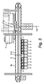
図6は、図1〜4に示す装置1で使用するための用量分割ステーション2の背面斜視図である。用量分割ステーション2はキャニスタとも呼ばれ、支持構造4に着脱可能に連結できるユニットで形成され、このユニットはハウジング20及びハウジング20を閉鎖するカバー21を備える。好ましくは、ハウジングは少なくとも部分的に透明な材料で製造され、これによって、用量分割ステーション2を開けることなく、用量分割ステーション2の充填度合いを決定できる。ハウジング20の外側には、ハウジング内に保持される錠剤又は丸薬に対応する錠剤又は丸薬のための受承空間22を設ける。受承空間22は透明なカバー要素23を用いて覆われる。これにより、用量分割ステーション2をどの錠剤又は丸薬で充填しなければならないかを即座に確認できる。図7に示す用量分割ステーション2の正面斜視図では、用量分割ステーション2の内部機構を可視化するために、ハウジング20を部分的に透明にして図示している。図示したように、ハウジング20は軸回転可能な個別化ホイール24を収容し、この個別化ホイール24は、ハウジング20に着脱可能に取り付けられ、軸回転中に単一の錠剤又は単一の丸薬を分離するよう適合され、続いてこれら単一の錠剤又は丸薬を、ハウジング内に配設された落下ガイド25を介してハウジング20から除去して、落下ガイド25に接続された落下チューブ7の通過用開口13に輸送できる。個別化ホイール24は、その周縁部にわたって配置された、丸薬又は錠剤のための複数の受承空間26を備える。受承空間26のサイズは一般に、供給中に保持されることになる丸薬又は錠剤のサイズに適合させることができる。個別化ホイール24は、これもまたハウジング20が内包する電気モータ27によって軸回転できる。落下ガイド25内にはセンサ28が配設され、このセンサ28は分離された丸薬又は錠剤が落下する瞬間を検出でき、これによってハウジング20が空になったかどうかも検出できる。用量分割ステーション2は装置1の外側から視認可能であり、発生し得る用量分割ステーション2の補充のためにアクセス可能である。ハウジング20は一般に複数のLED(図示せず)を備え、これによって、特に、用量分割ステーション2を補充しなければならない場合又は用量分割ステーション2が誤動作を起こしている場合に、用量分割ステーション2の現在の状態を表示できる。
FIG. 6 is a rear perspective view of a
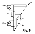
図8は、図1〜4に示す装置1で使用するための収集容器17の斜視図であり、図9はこの収集手段17の側面図である。収集容器17は、コンベヤベルト15の設置手段16と噛合して協働するための設置手段29を備える。収集容器17の安定性を向上するために、収集容器17は、コンベヤベルト15の周囲をクランプ留め又は少なくとも係合するための2つの固定溝30a、30bを備える。収集容器17の上側は開放形態であり、漏斗状の形状を有し、落下チューブ7から落下した薬品ポーションを受承できる。収集容器17の下側には枢動可能な閉鎖要素31が設けられ、この閉鎖要素31は操作用舌状部を備え、これによって閉鎖要素31を枢動させることができ、収集容器17を開いて内容物を取り出すことができる。収集容器17は一般に、収集容器17を閉鎖する位置の方向に閉鎖要素31を付勢するための、例えば圧縮バネ等のバイアス付与要素(図示せず)を備え、これによって収集容器17が誤って開くのを防止できる。
FIG. 8 is a perspective view of a
図10、11は、図1〜4に示す装置1に適用される排出及び包装ステーション3の正面斜視図及び背面斜視図である。包装ステーション3は箔ロール32を備え、電気モータ33を用いてこの箔ロール32の巻きを解くことができ、その後、巻きを解かれた箔34は、複数の案内ローラ35を介して、空にするべき収集容器17の方向へ案内される。図10、11の両方において、箔34の輸送方向を矢印で示す。収集容器17を空にするために箔34を収集手段17の下に輸送する前に、箔34を長手方向に折り、収集容器17を開いた後に薬剤を受承できるV字型の折り目36を生成する。包装18を完全に封止できるように、箔34は2つの横断方向封止及び長手方向封止を備えることができる。長手方向封止の作製時には2本の加熱バー37(そのうち一本の加熱バー37のみを図示する)を使用し、これら加熱バー37は、互いに接着される箔の2つの部分の両側を押圧し、これによって箔の上記部分を溶着して、長手方向封止を形成する。加熱バー37が箔に接着するのを防止するために、各加熱バー37が、特にテフロン(登録商標)であるプラスチックから製造された固定ストリップ又は変位可能なバンド38を介して箔34を係合させると有利である。横断方向封止はまた、2つの直立した回転可能な加熱バー39によって生成され、これら加熱バー39は互いに協働し、箔の一部を互いに対して押圧して、横断方向封止を実現する。更に包装18は、任意にラベルを備えることができる。連続した複数の包装18は、第1の例においては相互に接続されたままとし、包装ストリップを形成する。
10 and 11 are a front perspective view and a rear perspective view of the discharge and
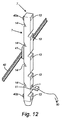
図12は落下チューブ7を示し、この落下チューブ7は、搬送手段6a、6bの設置手段8と協働するための2つの噛合設置要素40a、40bを備える。しかしながら、図12に示す落下チューブ7の特定の特徴は、落下チューブ7が一意識別子71を備えることである。この識別子71は単なる番号とすることができる。あるいは、識別子はバーコード又はRFIDタグによって提供できる。提供される識別子の種類は本発明にとって重要ではないが、落下チューブ識別子データを読み出すために使用される読み出し手段/識別手段の種類に影響する。しかしながら、落下チューブと設置手段との関連付けは重要である。
FIG. 12 shows a drop tube 7, which comprises two meshing
図13は、落下チューブのある実施形態を示す。上述のように、落下チューブは少なくとも2つの部分を備えてよく、図示した実施形態では、これら少なくとも2つの部分は基部7b及び前部7aとして設けられている。この実施形態では、基部7bは設置用梁52に着脱可能に接続され、この設置用梁52はコンベヤベルト(図示せず)に着脱可能に接続される。前部7aは、一意落下チューブ識別子と、一種の漏斗形状を有する複数の投入開口13とを備える。用量分割ステーション(図示せず)は、1用量の固形薬品ポーションを複数放出し、これは送り出し開口を介して用量分割ステーションを出て、投入開口13を介して落下チューブ7の前部7aに入る。いずれの種類の薬品ポーションが投入開口を通過できさえすれば、投入開口の形状/構成は重要ではない。例えば投入開口は、図12に示されているように、前部の単純な開口として形成できる。
FIG. 13 shows an embodiment with a drop tube. As mentioned above, the drop tube may comprise at least two parts, and in the illustrated embodiment these at least two parts are provided as a
図示した落下チューブの前部7aは、落下チューブ7の基部7bに着脱可能に接続される。図示した実施形態では、前部7aは多数の保持手段50aを備え、基部7bは多数の噛合用開口50bを備え、図示した実施形態では、この噛合用開口50bは細長い孔の形状を有する。前部7aはまた、落下チューブの上部に配置されたラッチ要素50cによって固定される。
The
前部7aを取り外すためには、ラッチ要素を解放して前部を持ち上げ、基部7bから引き抜く。(例えば両部分を清掃した後に)落下チューブを組み立てるためには、逆の手順を実行する。
In order to remove the
落下チューブ7の基部7bは多数の狭窄部14を備え、これら狭窄部14は、固形薬品ポーションの落下速度を制限し、また落下する薬剤を、前部の投入開口/用量分割ステーションの送り出し開口から離れるように案内することによって、落下する薬品ポーションが用量分割ステーションの送り出し開口に入るのを防止する。
The
図示した実施形態では、落下チューブの基部7bは2つのセンサ53、54を備える。センサ54は基部7aの下側セクションに配設され、落下する薬品ポーションの数を監視するよう適合される。このセンサは制御ユニット(図示せず)に連結され、この制御ユニットは、センサ54を通過した薬品ポーションの数に応じて、このセンサが配設されている落下チューブの保守作業を開始できる。
In the illustrated embodiment, the
センサ53は落下チューブの基部7b内のいずれかの場所に配設され、基部の内側表面の汚染を監視するよう適合される。このような汚染が所定の限界を超えると、このセンサ53も連結されている制御ユニットはすぐに保守作業を開始できる。
The
本発明は、本明細書で図示及び説明した例示的実施形態に限定されず、添付の請求項の範囲内で、当業者に自明である多数の変形例が可能であることは明らかであろう。 It will be apparent that the present invention is not limited to the exemplary embodiments shown and described herein, and that many variations will be apparent to those skilled in the art within the scope of the appended claims. .
Claims (18)
前記装置(1)は:
それぞれが出口(25)を有する、固形薬品ポーションを吐出するための複数の用量分割ステーション(2)を備え、
前記用量分割ステーション(2)が吐出した1用量の固形薬品ポーションを収集するため、及び前記1用量の固形薬品ポーションを包装手段(3)へと送るための、複数の収集手段(7、17)を有し、前記収集手段(7、17)は、一意収集手段識別子を備える識別子手段(71)を備え、
搬送手段(6a、6b、15)は、前記搬送手段の移動経路に沿って延在するチェーンに配設された設置位置に、複数の設置手段(8、16)を備え、各前記収集手段(7、17)は前記設置手段(8、16)のうちの1つに着脱可能に設置されて、前記搬送手段(6a、6b、15)によって前記用量分割ステーション(2)に沿って移動させられ、これによって前記収集手段(7、17)は、前記用量分割ステーション(2)の前記出口(25)において吐出された前記固形薬品ポーションを受承できるように動作し、;
前記用量分割ステーション、前記搬送手段及び前記包装手段の動作を制御するための制御手段(19)と前記制御手段(19)に連結された、前記収集手段識別子を入力するための入力手段(80、81)
を備え、
前記制御手段は、各前記設置手段又は前記設置位置に割り当てられた識別子と、前記設置手段に設置された前記収集手段の前記一意収集手段識別子との間のマッピングを保全するよう構成される、1用量の固形薬品ポーションを包装するための装置(1)。 An apparatus (1) for packaging a dose of a solid drug portion,
The device (1) is:
Comprising a plurality of dose dividing stations (2) for dispensing solid drug portions, each having an outlet (25);
A plurality of collecting means (7, 17) for collecting a dose of solid drug portion dispensed by said dose dividing station (2) and for sending said dose of solid drug portion to packaging means (3) The collection means (7, 17) comprises identifier means (71) comprising a unique collection means identifier;
The conveying means (6a, 6b, 15) includes a plurality of installation means (8, 16) at an installation position arranged on a chain extending along the movement path of the conveying means, and each collecting means ( 7, 17) is detachably installed in one of the installation means (8, 16) and is moved along the dose dividing station (2) by the transport means (6a, 6b, 15). , Whereby the collecting means (7, 17) operate to receive the solid drug portion dispensed at the outlet (25) of the dose dividing station (2);
Control means (19) for controlling the operation of the dose dividing station, the transport means and the packaging means and an input means (80, connected to the control means (19) for inputting the collection means identifier 81)
With
The control means is configured to maintain a mapping between an identifier assigned to each installation means or the installation location and the unique collection means identifier of the collection means installed in the installation means. Device (1) for packaging doses of solid drug portions.
前記マーカは、前記設置手段(8、16)と共に移動し、
前記制御手段(19)は、移動する前記マーカを検出するための固定基準位置センサに連結され、
各前記設置手段(8、16)又は前記設置位置に割り当てられた前記識別子は、前記基準位置から前記設置位置までの距離に相当するか、又は前記距離の関数である、請求項1に記載の1用量の固形薬品ポーションを包装するための装置。 The transport means (6a, 6b, 15) includes a marker at a reference position having an invariable relationship with the installation position of the installation means (8, 16),
The marker moves with the installation means (8, 16),
The control means (19) is connected to a fixed reference position sensor for detecting the moving marker,
The said identifier assigned to each said installation means (8, 16) or said installation position corresponds to a distance from the reference position to the installation position, or is a function of the distance. A device for packaging a dose of solid drug portion.
前記ステータス情報は、対応する前記収集手段の動作ステータスを示す、請求項1又は2に記載の1用量の固形薬品ポーションを包装するための装置。 The mapping includes status information associated with each of the collection means identifiers;
Apparatus for packaging a dose of solid drug portion according to claim 1 or 2, wherein the status information indicates the operational status of the corresponding collecting means.
前記入力手段は、前記機械可読識別子手段(71)を読み取るための読み取り手段(81)を備える、請求項1〜4のいずれか1項に記載の1用量の固形薬品ポーションを包装するための装置。 The identifier means (71) of the collecting means (7, 17) is machine readable;
5. A device for packaging a dose of solid drug portion according to any one of claims 1-4, wherein the input means comprises reading means (81) for reading the machine readable identifier means (71). .
各前記列(V)は、複数の前記用量分割ステーション(2)を含み、
各前記収集手段は、案内ダクト(7)及び前記案内ダクト(7)に関連する収集容器(17)を備え、
前記案内ダクト(7)は、前記固形薬品ポーションを、前記用量分割ステーション(2)の前記出口(25)から関連する前記収集容器(17)へと案内するよう配設される、請求項1〜6のいずれか1項に記載の1用量の固形薬品ポーションを包装するための装置。 The dose dividing stations (2) are arranged in a plurality of parallel rows (V),
Each said row (V) comprises a plurality of said dose dividing stations (2),
Each said collecting means comprises a guide duct (7) and a collection container (17) associated with said guide duct (7),
The guide duct (7) is arranged to guide the solid drug portion from the outlet (25) of the dose dividing station (2) to the associated collection container (17). 7. A device for packaging a dose of a solid drug portion according to any one of claims 6.
前記案内ダクト(7)は、前記第1の無端コンベヤ(6a、6b)の不変の設置位置に連結され、
前記収集容器(17)は、前記第2の無端コンベヤ(15)の不変の設置位置に連結される、請求項8に記載の1用量の固形薬品ポーションを包装するための装置。 The transport means comprises a first endless conveyor (6a, 6b) and a second endless conveyor (15),
The guide duct (7) is connected to an unchanging installation position of the first endless conveyor (6a, 6b),
9. The device for packaging a dose of solid drug portion according to claim 8, wherein the collection container (17) is connected to an unchanging installation position of the second endless conveyor (15).
前記装置は:
固形薬品ポーションを吐出するための複数の用量分割ステーション;
前記用量分割ステーションが吐出した1用量の固形薬品ポーションを収集するため、及び前記1用量の固形薬品ポーションを包装手段へと送るための、複数の収集手段;
それぞれが1つの前記収集手段を受承するための複数の設置位置を備える、前記収集手段を搬送するための搬送手段(前記設置位置は、前記搬送手段の移動経路に沿って延在するチェーンに配設される);
前記用量分割ステーション、前記搬送手段及び前記包装手段の動作を制御するための制御手段;並びに
前記制御手段に連結された読み取り手段
を備える、方法において、
前記方法は:
a)一意収集手段識別子を各前記収集手段に割り当て、割り当てられた前記収集手段識別子を含む識別子手段を各前記収集手段に添付するステップ;
b)前記設置手段のうちの1つにおいて、各前記収集手段を前記搬送手段に着脱可能に設置し、これに続いて設置した前記収集手段それぞれの前記収集手段識別子を、前記読み取り手段によって読み取り、読み取った前記収集手段識別子を、対応する前記設置位置の前記識別子に関連付けるステップ;
c)前記収集手段識別子及び前記関連付けられた対応する設置位置の前記識別子のマッピングを保全するステップ;並びに
d)前記用量分割ステーションが吐出した前記固形薬品ポーションを前記収集手段が受承できるように、前記収集手段を前記用量分割ステーションに沿って搬送し、前記固形薬品ポーションを前記収集手段が収集し、収集した前記固形薬品ポーションを前記包装手段へと送るステップ
を含む、1用量の固形薬品ポーションを包装するための装置を動作させるための方法。 A method for operating a device for packaging a dose of a solid drug portion, comprising:
The device is:
Multiple dose division stations for dispensing solid drug portions;
A plurality of collecting means for collecting a dose of solid drug portion dispensed by the dose dividing station and for sending the dose of solid drug portion to a packaging means;
Transport means for transporting the collection means, each having a plurality of installation positions for receiving one collection means (the installation position is in a chain extending along the movement path of the transport means) Arranged);
A control means for controlling the operation of the dose dividing station, the conveying means and the packaging means; and a reading means coupled to the control means;
The method is:
a) assigning a unique collection means identifier to each collection means and attaching an identifier means including the assigned collection means identifier to each collection means;
b) In one of the installation means, each of the collection means is detachably installed on the transport means, and subsequently the collection means identifier of each of the collection means installed is read by the reading means, Associating the read collection means identifier with the identifier of the corresponding installation position;
c) maintaining a mapping of said collection means identifier and said associated corresponding location location identifier; and d) so that said collection means can accept said solid drug portion dispensed by said dose dividing station. Transporting the collection means along the dose dividing station, collecting the solid drug portion by the collection means and sending the collected solid drug portion to the packaging means; A method for operating a device for packaging.
対応する前記設置位置の前記識別子は、前記読み取り手段の位置にある前記収集手段のうち最初の1つに開始位置を割り当て、後に読み取り位置に来ることになる前記設置位置の走行位置番号を関連付けることによって、関連付けられる、請求項11に記載の1用量の固形薬品ポーションを包装するための装置を動作させるための方法。 In step b), after all the collecting means are installed on the transport means, all the collecting means are continuously moved along the reading means, thereby collecting the collection of each installed collecting means. Reads the means identifier,
The corresponding identifier of the installation position assigns a starting position to the first one of the collection means at the position of the reading means and associates a running position number of the installation position that will later come to the reading position A method for operating a device for packaging a dose of a solid drug portion according to claim 11.
汚染の程度を示すパラメータ、及び前記収集手段が収集して送り出す固形薬品ポーションの量に応じたパラメータを、各前記収集手段識別子に関連付けるステップ
を含む、請求項11又は12に記載の1用量の固形薬品ポーションを包装するための装置を動作させるための方法。 Said step d): for each said collecting means, observing the number of solid chemical portions collected and delivered by said collecting means; and a parameter indicating the degree of contamination and the solid chemical portions collected and delivered by said collecting means 13. A method for operating an apparatus for packaging a single dose of a solid drug portion according to claim 11 or 12, comprising the step of associating a parameter depending on the amount of each said means of collecting identifier.
対応する前記汚染の度合いを示すパラメータは前記清掃後にリセットされる、請求項13〜15のいずれか1項に記載の1用量の固形薬品ポーションを包装するための装置を動作させるための方法。 When the parameter indicating the degree of contamination exceeds a predetermined threshold, the collecting means is cleaned,
16. A method for operating a device for packaging a dose of a solid drug portion according to any one of claims 13-15, wherein the corresponding parameter indicating the degree of contamination is reset after the cleaning.
前記収集手段識別子は前記読み取り手段によって読み取られ、対応する前記設置位置の前記識別子と関連付けられる、請求項16に記載の1用量の固形薬品ポーションを包装するための装置を動作させるための方法。 The collecting means is removed from the installation position, subsequently cleaned outside the apparatus, and again installed on the transport means at one of the installation positions;
17. A method for operating a device for packaging a dose of solid drug portion according to claim 16, wherein the collecting means identifier is read by the reading means and associated with the identifier of the corresponding installation location.
前記搬送手段が前記設置位置を設置部位へと移動させた後で、前記収集手段を、前記設置位置のうちの1つにおいて再び前記搬送手段に設置できる、請求項17に記載の1用量の固形薬品ポーションを包装するための装置を動作させるための方法。 After the transport means has moved the collection means to the installation release site, the collection means can be removed from the installation position,
18. A dose of solid according to claim 17, wherein the collecting means can be installed again on the conveying means at one of the installation positions after the conveying means has moved the installation position to an installation site. A method for operating a device for packaging pharmaceutical potions.
Applications Claiming Priority (3)
| Application Number | Priority Date | Filing Date | Title |
|---|---|---|---|
| EP12182654.9 | 2012-08-31 | ||
| EP12182654.9A EP2703301B1 (en) | 2012-08-31 | 2012-08-31 | An apparatus for packaging dosed quantities of medicines and method for operating such apparatus |
| PCT/EP2013/067159 WO2014032995A1 (en) | 2012-08-31 | 2013-08-16 | An apparatus for packaging dosed quantities of medicines and method for operating such apparatus |
Publications (2)
| Publication Number | Publication Date |
|---|---|
| JP2015530138A JP2015530138A (en) | 2015-10-15 |
| JP6093445B2 true JP6093445B2 (en) | 2017-03-08 |
Family
ID=46762934
Family Applications (1)
| Application Number | Title | Priority Date | Filing Date |
|---|---|---|---|
| JP2015528952A Active JP6093445B2 (en) | 2012-08-31 | 2013-08-16 | Device for packing a dose of medicament and method for operating said device |
Country Status (13)
| Country | Link |
|---|---|
| US (1) | US9914554B2 (en) |
| EP (1) | EP2703301B1 (en) |
| JP (1) | JP6093445B2 (en) |
| KR (1) | KR102140446B1 (en) |
| CN (1) | CN104797500B (en) |
| AU (1) | AU2013307505C1 (en) |
| BR (1) | BR112015003867B1 (en) |
| CA (1) | CA2882612C (en) |
| DK (1) | DK2703301T3 (en) |
| ES (1) | ES2553444T3 (en) |
| MX (1) | MX355664B (en) |
| PT (1) | PT2703301E (en) |
| WO (1) | WO2014032995A1 (en) |
Families Citing this family (18)
| Publication number | Priority date | Publication date | Assignee | Title |
|---|---|---|---|---|
| NL2007384C2 (en) | 2011-09-09 | 2013-03-12 | Ppm Engineering B V | SYSTEM AND METHOD FOR PACKING DOSED QUANTITIES OF SOLID MEDICINES |
| DK2702979T3 (en) | 2012-08-31 | 2015-07-27 | Carefusion Switzerland 317 Sarl | An apparatus for packaging metered amounts of solid drug portions |
| CN105366274A (en) * | 2014-08-26 | 2016-03-02 | 深圳富泰宏精密工业有限公司 | Conveying device |
| US10490016B2 (en) | 2015-05-13 | 2019-11-26 | Carefusion Germany 326 Gmbh | Device for packaging medication portions |
| US10255524B2 (en) | 2016-06-03 | 2019-04-09 | Becton Dickinson Rowa Germany Gmbh | Method for providing a singling device of a storage and dispensing container |
| EP3252656A1 (en) * | 2016-06-03 | 2017-12-06 | Becton Dickinson Rowa Germany GmbH | Method for providing a separation device of a storage and dispensing station |
| US20180057268A1 (en) * | 2016-08-24 | 2018-03-01 | Otg Experience, Llc | Transportable Modular System For Packaging Items |
| US10380824B2 (en) | 2017-02-03 | 2019-08-13 | Becton Dickinson Rowa Germany Gmbh | Storage and dispensing station for blister packaging machine |
| US11148839B2 (en) * | 2017-04-07 | 2021-10-19 | Becton Dickinson Rowa Germany Gmbh | Device for packing drug portions |
| IT201700068513A1 (en) * | 2017-06-20 | 2018-12-20 | Nuova Ompi Srl | Improved method of monitoring in a drug container management line and related drug container management line |
| NL2019530B1 (en) * | 2017-09-12 | 2019-03-27 | Canister Dev B V | Device for packaging dosed quantities of solid medicines |
| DE102017129560B4 (en) * | 2017-12-04 | 2019-12-12 | AS-MEDICALS GmbH | Device and system for blistering medicines and method for operating the same |
| US11299346B1 (en) | 2018-08-13 | 2022-04-12 | Express Scripts Strategic Development, Inc. | Pharmacy order filling system and related methods |
| CN113023295A (en) * | 2019-12-24 | 2021-06-25 | 深圳诺博医疗科技有限公司 | Drug delivery structure and device thereof |
| US11279571B1 (en) * | 2021-02-09 | 2022-03-22 | Capital One Services, Llc | Instrument conveyance using a shuttle |
| US11498761B1 (en) | 2021-06-22 | 2022-11-15 | Vmi Holland B.V. | Method for dispensing discrete medicaments, a test station for testing a feeder unit, and a method for determining a fill level of a feeder unit |
| US11273103B1 (en) | 2021-06-22 | 2022-03-15 | Vmi Holland B.V. | Method, computer program product and dispensing device for dispensing discrete medicaments |
| US11673700B2 (en) | 2021-06-22 | 2023-06-13 | Vmi Holland B.V. | Device and methods for packaging medicaments with fault detection |
Family Cites Families (34)
| Publication number | Priority date | Publication date | Assignee | Title |
|---|---|---|---|---|
| US3746130A (en) * | 1967-12-12 | 1973-07-17 | R Bullas | Automated store system |
| US3925960A (en) * | 1974-04-18 | 1975-12-16 | Lakso Company Inc | Article counting and filling machine |
| FR2596299B1 (en) * | 1986-03-27 | 1989-08-11 | Cga Hbs | METHOD FOR MAKING LOTS OF SMALL COMPONENTS AND INSTALLATION FOR IMPLEMENTING SAME |
| JPH03162204A (en) * | 1989-11-11 | 1991-07-12 | Tokyo Shokai:Kk | Apparatus for subdivision-packing medicine |
| GB2240543A (en) * | 1990-02-06 | 1991-08-07 | Huang Ming Sheng | Medicine dispensing device |
| JPH04307062A (en) * | 1991-01-19 | 1992-10-29 | Tokyo Shokai:Kk | Prescription processor for medicine preparator |
| DE4104527A1 (en) * | 1991-02-14 | 1992-08-20 | Knapp Logistik Automation | DEVICE AND METHOD FOR PICKING PIECE |
| US5481855A (en) * | 1994-09-27 | 1996-01-09 | Yuyama; Shoji | Tablet packing device and method for controlling the same |
| JP3779364B2 (en) * | 1996-01-26 | 2006-05-24 | 株式会社湯山製作所 | Drug storage and removal device |
| JPH11278402A (en) * | 1998-03-26 | 1999-10-12 | Sanyo Electric Co Ltd | Tablet supply apparatus |
| US6208908B1 (en) * | 1999-04-27 | 2001-03-27 | Si Handling Systems, Inc. | Integrated order selection and distribution system |
| WO2001034090A1 (en) * | 1999-11-09 | 2001-05-17 | Sanyo Electric Co., Ltd. | Solid drug filling device |
| JP4405032B2 (en) * | 2000-03-28 | 2010-01-27 | 株式会社湯山製作所 | Drug dispensing device |
| JP2001287702A (en) * | 2000-04-11 | 2001-10-16 | Yuyama Manufacturing Co Ltd | Tablet filling apparatus |
| US6792136B1 (en) * | 2000-11-07 | 2004-09-14 | Trw Inc. | True color infrared photography and video |
| JP4778622B2 (en) * | 2001-01-31 | 2011-09-21 | 高園産業株式会社 | Drug packaging device |
| TWI225836B (en) * | 2002-02-20 | 2005-01-01 | Sanyo Electric Co | Medicine supply apparatus |
| WO2004014285A2 (en) * | 2002-08-09 | 2004-02-19 | Mckesson Automation Systems, Inc. | Drug dispensing cabinet having a drawer interlink, counterbalance and locking system |
| JP4093856B2 (en) | 2002-12-25 | 2008-06-04 | 三洋電機株式会社 | Drug supply device |
| US20040247421A1 (en) * | 2003-03-20 | 2004-12-09 | Saunders Leland N. | Pick-to-light system |
| WO2004089757A1 (en) * | 2003-04-02 | 2004-10-21 | Yuyama Mfg. Co., Ltd. | Tablet packaging device |
| JP4495542B2 (en) * | 2004-08-11 | 2010-07-07 | 株式会社湯山製作所 | Drug packaging device |
| US7497064B2 (en) * | 2004-10-01 | 2009-03-03 | Zoran Momich | Vertical cartoner |
| JP4606342B2 (en) * | 2006-02-06 | 2011-01-05 | 株式会社トーショー | Drug packaging device |
| KR100744427B1 (en) * | 2006-06-05 | 2007-08-01 | (주)제이브이엠 | Apparatus for identifying cassette using auto wrapping pill and method thereof |
| JP2007330411A (en) * | 2006-06-13 | 2007-12-27 | Tosho Inc | Tablet container packing machine |
| US8376130B2 (en) * | 2006-07-10 | 2013-02-19 | Muratec Automation Co., Ltd. | Direct drive modular belt conveyor, cartridge, and quick connect-disconnect constant velocity drive shaft, for high speed FOUP transport |
| US7950206B2 (en) * | 2008-06-27 | 2011-05-31 | Qem, Inc. | Pill dispenser with canisters having electronically readable/writeable identification |
| US8306651B2 (en) * | 2008-07-30 | 2012-11-06 | Chudy Group, LLC | Pharmacy will-call and prescription order article management system |
| US10916340B2 (en) * | 2008-12-05 | 2021-02-09 | Remedi Technology Holdings, Llc | System and methodology for filling prescriptions |
| JP5430450B2 (en) * | 2010-03-05 | 2014-02-26 | 株式会社トーショー | Medicine packaging machine |
| CN202022523U (en) * | 2011-03-30 | 2011-11-02 | 深圳市瑞驰智能系统有限公司 | Medicine delivering system |
| NL2007384C2 (en) | 2011-09-09 | 2013-03-12 | Ppm Engineering B V | SYSTEM AND METHOD FOR PACKING DOSED QUANTITIES OF SOLID MEDICINES |
| US9665688B2 (en) * | 2012-05-15 | 2017-05-30 | Tension International Inc. | Product dispensing system and method with redundant container induction |
-
2012
- 2012-08-31 DK DK12182654.9T patent/DK2703301T3/en active
- 2012-08-31 PT PT121826549T patent/PT2703301E/en unknown
- 2012-08-31 ES ES12182654.9T patent/ES2553444T3/en active Active
- 2012-08-31 EP EP12182654.9A patent/EP2703301B1/en active Active
-
2013
- 2013-08-16 CN CN201380045379.1A patent/CN104797500B/en active Active
- 2013-08-16 CA CA2882612A patent/CA2882612C/en active Active
- 2013-08-16 US US14/423,313 patent/US9914554B2/en active Active
- 2013-08-16 MX MX2015002654A patent/MX355664B/en active IP Right Grant
- 2013-08-16 BR BR112015003867-0A patent/BR112015003867B1/en active IP Right Grant
- 2013-08-16 AU AU2013307505A patent/AU2013307505C1/en active Active
- 2013-08-16 WO PCT/EP2013/067159 patent/WO2014032995A1/en active Application Filing
- 2013-08-16 KR KR1020157005159A patent/KR102140446B1/en active IP Right Grant
- 2013-08-16 JP JP2015528952A patent/JP6093445B2/en active Active
Also Published As
| Publication number | Publication date |
|---|---|
| WO2014032995A1 (en) | 2014-03-06 |
| US9914554B2 (en) | 2018-03-13 |
| CA2882612C (en) | 2020-07-07 |
| US20150251789A1 (en) | 2015-09-10 |
| AU2013307505B2 (en) | 2017-03-09 |
| JP2015530138A (en) | 2015-10-15 |
| CA2882612A1 (en) | 2014-03-06 |
| EP2703301B1 (en) | 2015-09-30 |
| BR112015003867A8 (en) | 2018-12-04 |
| MX2015002654A (en) | 2015-08-14 |
| DK2703301T3 (en) | 2015-12-07 |
| CN104797500B (en) | 2016-08-24 |
| MX355664B (en) | 2018-04-25 |
| KR102140446B1 (en) | 2020-08-04 |
| KR20150048747A (en) | 2015-05-07 |
| BR112015003867B1 (en) | 2020-12-08 |
| AU2013307505C1 (en) | 2017-12-14 |
| ES2553444T3 (en) | 2015-12-09 |
| PT2703301E (en) | 2015-11-30 |
| EP2703301A1 (en) | 2014-03-05 |
| CN104797500A (en) | 2015-07-22 |
| BR112015003867A2 (en) | 2017-07-04 |
| AU2013307505A1 (en) | 2015-03-12 |
Similar Documents
| Publication | Publication Date | Title |
|---|---|---|
| JP6093445B2 (en) | Device for packing a dose of medicament and method for operating said device | |
| US11254454B2 (en) | System and method for packaging dosed quantities of solid drug portions | |
| JP6120968B2 (en) | Device for packaging one dose of solid drug portion | |
| JP2017225832A (en) | Medicine supply device | |
| JP2003512088A (en) | Drug collection system | |
| JP6097397B2 (en) | Apparatus for packaging a dose of solid drug portion comprising a mobile collection container and a dose splitting station |
Legal Events
| Date | Code | Title | Description |
|---|---|---|---|
| A621 | Written request for application examination |
Free format text: JAPANESE INTERMEDIATE CODE: A621 Effective date: 20160315 |
|
| A977 | Report on retrieval |
Free format text: JAPANESE INTERMEDIATE CODE: A971007 Effective date: 20161221 |
|
| TRDD | Decision of grant or rejection written | ||
| A01 | Written decision to grant a patent or to grant a registration (utility model) |
Free format text: JAPANESE INTERMEDIATE CODE: A01 Effective date: 20170124 |
|
| A61 | First payment of annual fees (during grant procedure) |
Free format text: JAPANESE INTERMEDIATE CODE: A61 Effective date: 20170210 |
|
| R150 | Certificate of patent or registration of utility model |
Ref document number: 6093445 Country of ref document: JP Free format text: JAPANESE INTERMEDIATE CODE: R150 |
|
| R250 | Receipt of annual fees |
Free format text: JAPANESE INTERMEDIATE CODE: R250 |
|
| R250 | Receipt of annual fees |
Free format text: JAPANESE INTERMEDIATE CODE: R250 |
|
| R250 | Receipt of annual fees |
Free format text: JAPANESE INTERMEDIATE CODE: R250 |
|
| R250 | Receipt of annual fees |
Free format text: JAPANESE INTERMEDIATE CODE: R250 |
|
| R250 | Receipt of annual fees |
Free format text: JAPANESE INTERMEDIATE CODE: R250 |