JP6090128B2 - Front body structure of the vehicle - Google Patents
Front body structure of the vehicle Download PDFInfo
- Publication number
- JP6090128B2 JP6090128B2 JP2013241672A JP2013241672A JP6090128B2 JP 6090128 B2 JP6090128 B2 JP 6090128B2 JP 2013241672 A JP2013241672 A JP 2013241672A JP 2013241672 A JP2013241672 A JP 2013241672A JP 6090128 B2 JP6090128 B2 JP 6090128B2
- Authority
- JP
- Japan
- Prior art keywords
- vehicle
- width direction
- vehicle width
- steering
- vehicle body
- Prior art date
- Legal status (The legal status is an assumption and is not a legal conclusion. Google has not performed a legal analysis and makes no representation as to the accuracy of the status listed.)
- Active
Links
Images


Classifications
-
- B—PERFORMING OPERATIONS; TRANSPORTING
- B60—VEHICLES IN GENERAL
- B60R—VEHICLES, VEHICLE FITTINGS, OR VEHICLE PARTS, NOT OTHERWISE PROVIDED FOR
- B60R21/00—Arrangements or fittings on vehicles for protecting or preventing injuries to occupants or pedestrians in case of accidents or other traffic risks
- B60R21/02—Occupant safety arrangements or fittings, e.g. crash pads
- B60R21/16—Inflatable occupant restraints or confinements designed to inflate upon impact or impending impact, e.g. air bags
- B60R21/20—Arrangements for storing inflatable members in their non-use or deflated condition; Arrangement or mounting of air bag modules or components
- B60R21/203—Arrangements for storing inflatable members in their non-use or deflated condition; Arrangement or mounting of air bag modules or components in steering wheels or steering columns
-
- B—PERFORMING OPERATIONS; TRANSPORTING
- B62—LAND VEHICLES FOR TRAVELLING OTHERWISE THAN ON RAILS
- B62D—MOTOR VEHICLES; TRAILERS
- B62D25/00—Superstructure or monocoque structure sub-units; Parts or details thereof not otherwise provided for
- B62D25/08—Front or rear portions
- B62D25/14—Dashboards as superstructure sub-units
- B62D25/145—Dashboards as superstructure sub-units having a crossbeam incorporated therein
- B62D25/147—Dashboards as superstructure sub-units having a crossbeam incorporated therein with adjustable connection to the A-pillars
Landscapes
- Engineering & Computer Science (AREA)
- Mechanical Engineering (AREA)
- Chemical & Material Sciences (AREA)
- Combustion & Propulsion (AREA)
- Transportation (AREA)
- Body Structure For Vehicles (AREA)
- Air Bags (AREA)
Description
この発明は、エアバッグを備えたステアリング装置を支持するとともに、車幅方向に延びるステアリングメンバとを備えた車両の前部車体構造に関する。 The present invention relates to a front vehicle body structure for a vehicle that supports a steering device including an airbag and includes a steering member that extends in the vehicle width direction.
一般に、オフセット衝突によってヒンジピラーが後退したり、内倒れ変形する場合、ヒンジピラーに対してサイドブラケットによって結合されたステアリングメンバは、センタステイ近傍を支点として車体後方へ屈曲することがある。 In general, when the hinge pillar moves backward or deforms inward due to an offset collision, the steering member coupled to the hinge pillar by the side bracket may bend toward the rear of the vehicle body around the center stay.
このように、ステアリングメンバが車体後方へ屈曲すると、ステアリングメンバに支持されたステアリング装置は車幅方向内側に移動し、ステアリング装置に備えたエアバッグによる乗員の拘束位置が車幅方向内側にずれる虞があった。特に、車両のポール衝突やスモールオーバラップ前突時には、このような虞が顕著になる。 As described above, when the steering member is bent rearward, the steering device supported by the steering member moves inward in the vehicle width direction, and the restraining position of the occupant by the airbag provided in the steering device may shift inward in the vehicle width direction. was there. In particular, such a concern becomes conspicuous at the time of a vehicle pole collision or a small overlap front collision.
例えば、特許文献1では、ステアリングメンバにおける、運転席側のサイドブラケットとステアリング支持部との間に脆弱部を形成することで、車両の前突時に脆弱部を先に屈曲させて、ステアリング装置の車幅方向内側への移動を抑制する構造が開示されている。 For example, in Patent Document 1, by forming a fragile portion between the side bracket on the driver's seat side and the steering support portion in the steering member, the fragile portion is bent first at the time of a frontal collision of the vehicle. A structure for suppressing movement inward in the vehicle width direction is disclosed.
なお、ステアリングメンバは、ステアリングメンバを構成するビーム部材の端部に設けたサイドブラケットをヒンジピラーに固定する、つまり、ステアリングメンバの端部は、サイドブラケットを介してヒンジピラーに固定されており、ビーム部材の端面とヒンジピラーとの間に隙間が形成される場合がある。 The steering member fixes the side bracket provided at the end of the beam member constituting the steering member to the hinge pillar, that is, the end of the steering member is fixed to the hinge pillar via the side bracket. There may be a case where a gap is formed between the end face of the metal plate and the hinge pillar.
特に、搭載時における必要隙間などからステアリングメンバの幅寸法は車体間の幅寸法、つまり車幅方向両側のヒンジピラーにおける取付箇所同士の間隔よりも短く設定され、一方のサイドブラケットをヒンジピラー車体に突当てた状態に配置するとともに、他方のサイドブラケットをヒンジピラーとの間に形成される隙間を埋めるよう、例えば特許文献2に開示された長さ調節手段を有する調整ナット等の締結具を用いて車体に固定された場合、ステアリングメンバの端面とヒンジピラーとの間に隙間が形成される。 In particular, due to the necessary clearance during mounting, the width of the steering member is set to be shorter than the width between the vehicle bodies, that is, the distance between the mounting portions of the hinge pillars on both sides in the vehicle width direction, and one side bracket abuts against the hinge pillar vehicle body. In order to fill the gap formed between the other side bracket and the hinge pillar, for example, a fastener such as an adjustment nut having a length adjusting means disclosed in Patent Document 2 is attached to the vehicle body. When fixed, a gap is formed between the end face of the steering member and the hinge pillar.
このように、ステアリングメンバを構成するビーム部材の端面とヒンジピラーとの間に隙間が形成されると、車両の前突によって運転席側のヒンジピラーが内倒れした際に、ヒンジピラーに固定されたサイドブラケットが変形して、ステアリングメンバが車幅方向の助手席側にスライド移動しやすくなる。 As described above, when a gap is formed between the end face of the beam member constituting the steering member and the hinge pillar, the side bracket fixed to the hinge pillar when the hinge pillar on the driver's seat side falls inward due to the front collision of the vehicle. As a result, the steering member can easily slide and move toward the passenger seat in the vehicle width direction.
また、サイドブラケットが大きく変形した場合、特許文献1に記載された脆弱部を有するステアリングメンバを用いても、ステアリングメンバへ入力される荷重が分散され、脆弱部を効率よく屈曲させることができず、ステアリングメンバが車体後方へ屈曲して、ステアリング装置が車幅方向内側へ大きく移動する虞があった。 In addition, when the side bracket is greatly deformed, even if the steering member having the fragile portion described in Patent Document 1 is used, the load input to the steering member is dispersed, and the fragile portion cannot be bent efficiently. There is a possibility that the steering member is bent rearward of the vehicle body and the steering device moves greatly inward in the vehicle width direction.
そこで、この発明は、車両の前突時のステアリング装置の車幅方向内側への移動を抑制して、エアバッグで乗員を拘束することができる簡易な構造の前部車体構造を提供することを目的とする。 SUMMARY OF THE INVENTION Accordingly, the present invention provides a front body structure having a simple structure capable of restraining the occupant from being restrained by an air bag by restraining the steering device from moving inward in the vehicle width direction at the time of a frontal collision of the vehicle. Objective.
この発明の車両の前部車体構造は、エアバッグを備えたステアリング装置と、車幅方向に延びるとともに、前記ステアリング装置を支持するステアリングメンバとを備えた車両の前部車体構造であって、前記ステアリングメンバは、車幅方向に延びるビーム部材と、前記ステアリング装置を支持するステアリング支持部と、前記ビーム部材の両側端にそれぞれ設けられ、車体側部に固定されるサイドブラケットとを有し、前記ビーム部材におけるステアリング支持部と運転席側の前記サイドブラケットとの間において、運転席側の車体側部への車両前後方向の入力荷重に対して脆弱に形成された脆弱部を備えるとともに、前記ビーム部材における助手席側の前記サイドブラケットよりも車幅方向外側に延設され、前記入力荷重による車体変形時に前記車体側部に当接して、前記ステアリングメンバの助手席側へのスライド移動を抑制する延設部を備え、前記ビーム部材の両側端のそれぞれに設けられた前記サイドブラケット同士の車幅方向の間隔は、車幅方向両側の前記車体側部同士の間隔より短く設定され、助手席側の前記サイドブラケットを、長さ調節手段を有する締結具を用いて前記車体側部と締結固定するとともに、前記長さ調整手段の長さを短く設定した前記締結具の外側端部と前記延設部の外側端部とが、車幅方向において、互いに略同一位置となるように配設されたものである。 A vehicle front body structure according to the present invention is a vehicle front body structure including a steering device including an airbag and a steering member that extends in a vehicle width direction and supports the steering device, The steering member has a beam member extending in the vehicle width direction, a steering support portion that supports the steering device, and a side bracket that is provided on each side end of the beam member and is fixed to a side portion of the vehicle body, Between the steering support portion of the beam member and the side bracket on the driver's seat side, there is provided a fragile portion that is fragile to an input load in the vehicle longitudinal direction to the vehicle body side portion on the driver's seat side, and the beam It extends in the vehicle width direction outer side than the side brackets of the passenger seat side of the member, body deformation by the input load Wherein the vehicle body side portion abuts, before Symbol with suppressing extension portion of the sliding movement of the passenger side of the steering member, a vehicle width of the side brackets to each other provided on each of both side ends of said beam member The direction interval is set to be shorter than the interval between the vehicle body side portions on both sides in the vehicle width direction, and the side bracket on the passenger seat side is fastened and fixed to the vehicle body side portion using a fastener having a length adjusting means. In addition, the outer end portion of the fastener and the outer end portion of the extending portion, in which the length of the length adjusting means is set to be short, are disposed so as to be substantially at the same position in the vehicle width direction. Is.
この構成によれば、簡単な構造で、エアバックを備えたステアリング装置の車幅方向内側への移動を抑制することができる。
詳しくは、前記ビーム部材における助手席側の前記サイドブラケットよりも車幅方向外側に延設部を設けることで、前突時に運転席側の車体側部が内倒れした場合であっても、変形開始の早い段階で延設部が助手席側の車体側部に当接して、つまり、延設部が助手席側の車体側部に先当たりして、サイドブラケットの変形によるステアリングメンバの車幅方向助手席側への移動を抑制することができる。
According to this configuration, it is possible to suppress movement of the steering device including the airbag inward in the vehicle width direction with a simple structure.
Specifically, by providing an extending portion on the outer side in the vehicle width direction than the side bracket on the passenger seat side in the beam member, even if the vehicle body side portion on the driver seat side falls inward during a front collision, In the early stage of the start, the extension part comes into contact with the vehicle body side part on the passenger seat side, that is, the extension part comes in contact with the vehicle body side part on the passenger seat side, and the vehicle width of the steering member due to the deformation of the side bracket. The movement to the direction passenger seat side can be suppressed.
また、前記入力荷重による車体変形時に、延設部が直接、車体側部に当接するため、脆弱部を備えたビーム部材に対して荷重を効率的に入力し、脆弱部の変形を促進することで、ステアリングメンバの車体後方への屈曲を抑制することができる。 Further, when the vehicle body is deformed due to the input load, the extension portion directly contacts the vehicle body side portion, so that the load is efficiently input to the beam member having the fragile portion, and the deformation of the fragile portion is promoted. Thus, the bending of the steering member toward the rear of the vehicle body can be suppressed.
このように、上記構成により、簡単な構成でステアリング装置の車幅方向内側への移動を抑制することができる。特に、ヒンジピラーの後退や内倒れ変形が顕著である車両のポール衝突やスモールオーバラップ前突のような場合を考慮すると、特許文献1の構造に加えて、他の部位での変形を抑制するための充分な補強や板厚確保などの追加の対策によってコストアップや重量増加となるが、上記構成の場合、上述のような他の部位に対する追加の対策をすることなく、あるいは最小限の対策で、ステアリングメンバの車幅方向助手席側への移動の抑制、及び脆弱部の変形を促進してステアリングメンバの車体後方への屈曲を抑制することができる。したがって、ステアリング装置の車幅方向内側への移動を抑制し、ステアリング装置に備えたエアバッグによる乗員の拘束位置が車幅方向内側にずれる虞を抑制することができる。 Thus, with the above configuration, the steering device can be prevented from moving inward in the vehicle width direction with a simple configuration. In particular, in consideration of cases such as a vehicle pole collision or a small overlap front collision where retraction of the hinge pillar or inward deformation is significant, in addition to the structure of Patent Document 1, in order to suppress deformation at other parts Additional measures such as sufficient reinforcement and securing plate thickness will increase costs and increase weight. However, in the case of the above configuration, additional measures for other parts as described above may be taken, or with minimal measures. Further, it is possible to suppress the steering member from being bent toward the rear of the vehicle body by suppressing the movement of the steering member toward the passenger seat side in the vehicle width direction and the deformation of the fragile portion. Therefore, the movement of the steering device to the inside in the vehicle width direction can be suppressed, and the possibility that the restraining position of the occupant by the airbag provided in the steering device can shift to the inside in the vehicle width direction can be suppressed.
また上記構成によれば、ステアリングメンバの車両搭載性を満足させつつ、ステアリング装置及びエアバッグの車幅方向内側への移動を抑制することができる。 Moreover, according to the said structure, the movement to the vehicle width direction inside of a steering device and an airbag can be suppressed, satisfying the vehicle mounting property of a steering member.
詳述すると、ステアリングメンバを所定の搭載箇所に配置した状態で、運転席側の車体側部に一方のサイドブラケットを突当てて配置すると、助手席側の車体側部と、前記長さ調整手段の長さを短く設定した状態における前記締結具の外側端部及び前記延設部の外側端部との間に隙間が確保されるため、ステアリングメンバの車両における所定箇所への車両搭載性を向上することができる。また、このように、車両搭載性を向上するための隙間が形成された場合であっても、上述のように延設部を設けているため、前突時における運転席側の車体側部の内倒れによって、延設部が助手席側の車体側部に先当たりして、サイドブラケットの変形によるステアリングメンバの車幅方向助手席側への移動を抑制するとともに、ステアリングメンバの車体後方への屈曲を抑制することができる。 More specifically, when the steering member is disposed at a predetermined mounting location, when one side bracket is abutted against the vehicle body side portion on the driver's seat side, the vehicle body side portion on the passenger seat side and the length adjusting means are arranged. Since a gap is secured between the outer end of the fastener and the outer end of the extended portion in a state where the length of the steering member is set short, the vehicle mountability of the steering member at a predetermined position in the vehicle is improved. can do. In addition, even when the gap for improving the vehicle mountability is formed as described above, since the extending portion is provided as described above, the vehicle body side portion on the driver's seat side at the time of the front collision is provided. Due to the inward tilt, the extension part comes into contact with the side part of the vehicle body on the passenger seat side, and the movement of the steering member to the passenger seat side in the vehicle width direction due to the deformation of the side bracket is suppressed, and the steering member Bending can be suppressed.
なお、延設部は、ステアリングメンバと一体化された延設部、つまりビーム部材の助手席側端面から所定の長さ分、車幅方向内側にサイドブラケットを取り付けて延設部を形成してもよく、また、ビーム部材の助手席側端部にサイドブラケットを取付け、サイドブラケットの車幅方向外側におけるビーム部材が延長される位置に、ビーム部材と同等以上の強度を有する別部材を配置して延設部を設けてもよい。 The extended portion is an extended portion integrated with the steering member, that is, an extended portion is formed by attaching a side bracket to the inner side in the vehicle width direction by a predetermined length from the end surface on the passenger seat side of the beam member. In addition, a side bracket is attached to the end of the beam member on the passenger side, and another member having a strength equal to or greater than that of the beam member is disposed at a position where the beam member is extended outside the side bracket in the vehicle width direction. An extending portion may be provided.
また、延設部は、オフセット衝突によって後退したり、内倒れ変形するヒンジピラーなどの車体側部に対して、サイドブラケットの変形を抑制する、あるいは脆弱部の変形を促進するように当接すれば、設置状態において、延設部と車体側部との間に隙間があってもよいし、当接していてもよい。 Further, if the extending portion comes into contact with the vehicle body side portion such as a hinge pillar that retreats due to an offset collision or falls inwardly, or prevents the side bracket from being deformed, or promotes the deformation of the fragile portion, In the installed state, there may be a gap between the extending portion and the vehicle body side portion, or they may be in contact with each other .
この発明の一実施態様においては、前記脆弱部は、車幅方向に延在する横孔部と、車幅方向及び垂直断面方向に延在する縦孔部とを組み合わせて形成されたものである。
この構成によれば、縦孔部によってビーム部材の屈曲の開始を促進し、横孔部によってビーム部材の変形量を調整することで、脆弱部を効率よく屈曲させることができる。したがって、例えば、センタステイ近傍を支点としたステアリングメンバの車体後方への屈曲を防止し、脆弱部が効率よく屈曲して、前突時に運転席側の車体側部が内倒れした場合であっても、延設部が助手席側の車体側部に先当たりして、サイドブラケットの変形によるステアリングメンバの車幅方向助手席側への移動を抑制するとともに、ステアリングメンバの車体後方への屈曲を抑制することができる。
In one embodiment of this invention, the weak portion may include a horizontal hole portion extending in the vehicle width direction, those formed by combining the vertical hole portion extending in the vehicle width direction and the vertical cross-sectional direction is there.
According to this configuration, the fragile portion can be efficiently bent by promoting the start of bending of the beam member by the vertical hole portion and adjusting the deformation amount of the beam member by the horizontal hole portion. Therefore, for example, when the steering member around the center stay is prevented from bending to the rear of the vehicle body, the fragile part is bent efficiently, and the vehicle body side part on the driver's seat side falls down during a front collision. In addition, the extension part comes in contact with the side part of the vehicle body on the passenger seat side to suppress the movement of the steering member to the passenger seat side in the vehicle width direction due to the deformation of the side bracket, and to bend the steering member to the rear side of the vehicle body. Can be suppressed.
この発明の一実施態様においては、助手席側の車体側部における、車両側面視で前記延設部と少なくとも部分的に重複する位置に、前記車体側部を構成する内壁と外壁との間を車幅方向に延びる節部が配設されたものである。 In one embodiment of the present invention, in the vehicle body side portion on the passenger seat side, between the inner wall and the outer wall constituting the vehicle body side portion at a position at least partially overlapping with the extension portion in a vehicle side view. A node extending in the vehicle width direction is provided.
この構成によれば、内壁と外壁で構成する車体側部の剛性が向上し、例えば、前突時による車体側部の変形を抑制するとともに、車体側部が内倒れする場合の荷重をステアリングメンバに、効率的に入力し、脆弱部への効率的な荷重入力を促すことができる。 According to this configuration, the rigidity of the side part of the vehicle body constituted by the inner wall and the outer wall is improved. For example, the deformation of the side part of the vehicle body due to the front collision is suppressed, and the load when the vehicle body side part falls inward is reduced by the steering member. In addition, it is possible to promptly input the load efficiently to the weak part.
この発明の一実施態様においては、前記ステアリングメンバを車体フロアに固定するためのステー部材を、前記ステアリングメンバの車幅方向中間部に備え、前記ビーム部材は、運転席側の大径パイプと、助手席側の小径パイプとで形成され、前記ステー部材が前記大径パイプに固定されるとともに、前記ステー部材から前記小径パイプまで車幅方向に延設する補強部材が設けられたものである。 In one embodiment of the present invention, a stay member for fixing the steering member to a vehicle body floor is provided at an intermediate portion in the vehicle width direction of the steering member, and the beam member includes a large-diameter pipe on the driver's seat side, The stay member is fixed to the large-diameter pipe, and a reinforcing member extending in the vehicle width direction from the stay member to the small-diameter pipe is provided.
この構成によれば、例えば、前突時による車体側部の内倒れ等によるステアリングメンバへの荷重入力によって、屈曲の支点となって最も屈曲しやすい車幅方向中間となる断面変化部分において、車体フロアに固定されるステー部材と大径パイプと小径パイプの間を補強することで、効率的にステアリングメンバの補強ができ、他の部位を過度に補強する必要がなく、ステアリングメンバの車幅方向助手席側への移動を抑制するとともに、ステアリングメンバの車体後方への屈曲を抑制することができる。 According to this configuration, for example, at the cross-section change portion that is the middle in the vehicle width direction that is most likely to bend as a fulcrum of bending due to a load input to the steering member due to inward tilting of the side portion of the vehicle body due to a front collision, etc. By reinforcing the stay member fixed between the floor, the large-diameter pipe, and the small-diameter pipe, the steering member can be efficiently reinforced, and there is no need to excessively reinforce other parts. While suppressing the movement to the passenger seat side, it is possible to suppress the bending of the steering member toward the rear of the vehicle body.
この発明によれば、ビーム部材に設けた延設部が助手席側の車体側部に先当たりして、ステアリングメンバの車幅方向助手席側への移動を抑制し、ステアリング装置やエアバッグの車幅方向内側への移動を抑制することができる。 According to the present invention, the extending portion provided on the beam member comes in contact with the vehicle body side portion on the passenger seat side to suppress the movement of the steering member toward the passenger seat side in the vehicle width direction. Movement to the inside in the vehicle width direction can be suppressed.
以下、図面に基づいて本発明の実施形態を詳述する。
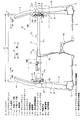
図1は、本発明の実施形態に係る構造を有する車両1の前部の平面図を示し、図2は、車室Sの前部を車両後方から見た図を示している。なお、図中において矢印(F)は車体前方、矢印(R)は車体後方を示し、矢印(IN)は車幅方向内側、矢印(OUT)は車幅方向外側を示している。さらに、矢印(W)は車幅方向を示し、矢印(Wd)は車幅方向Wにおけるステアリング装置40が配置された運転席側を示し、矢印(Wp)は車幅方向Wにおける助手席側を示している。
Hereinafter, embodiments of the present invention will be described in detail with reference to the drawings.
FIG. 1 is a plan view of a front portion of a vehicle 1 having a structure according to an embodiment of the present invention, and FIG. 2 is a view of the front portion of a passenger compartment S as viewed from the rear of the vehicle. In the figure, arrow (F) indicates the front of the vehicle body, arrow (R) indicates the rear of the vehicle body, arrow (IN) indicates the vehicle width direction inside, and arrow (OUT) indicates the vehicle width direction outside. Further, the arrow (W) indicates the vehicle width direction, the arrow (Wd) indicates the driver seat side where the
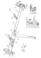
また、図3は図1のA−A線矢視断面図を示し、図4はステアリングメンバ10の斜視図を示し、図5は図3のB部についての説明図を示し、図6は図3のC部についての説明図を示している。
詳しくは、図5(a)は図3におけるB部の拡大図を示し、図5(b)は図3におけるB部の断面図を示している。同様に、図6(a)は図3におけるC部の拡大図を示し、図6(b)は図3におけるC部の断面図を示している。
また、図7はステアリングメンバ10の運転席側Wdの拡大斜視図を示し、図8はステアリングメンバ10の助手席側Wpの拡大斜視図を示している。
3 is a cross-sectional view taken along line AA in FIG. 1, FIG. 4 is a perspective view of the steering
Specifically, FIG. 5A shows an enlarged view of a portion B in FIG. 3, and FIG. 5B shows a cross-sectional view of the portion B in FIG. Similarly, FIG. 6A shows an enlarged view of a portion C in FIG. 3, and FIG. 6B shows a sectional view of the portion C in FIG.
FIG. 7 is an enlarged perspective view of the driver seat side Wd of the steering
図1、図2に示すように、本実施形態に係る車両は、その前部において、エンジンルームと車室Sと仕切り、該車室Sの前壁部を構成するダッシュパネル2を備えている。 As shown in FIG. 1 and FIG. 2, the vehicle according to the present embodiment includes a dash panel 2 that partitions an engine room and a vehicle compartment S and constitutes a front wall portion of the vehicle compartment S at a front portion thereof. .
そして、車両前部におけるダッシュパネル2よりも車幅方向外側OUTには、ダッシュパネル2の側端部に沿って上下に延びる左右一対のヒンジピラー3が立設されている。そして、このヒンジピラー3の上部には、前部が低く、後部が高くなるようにフロントピラー4(図2参照)が配設されている。一方、ヒンジピラー3の下部には、フロントサイドフレーム3よりも車幅方向外側OUTで車両前後方向に延びる左右一対のサイドシル5が配設されている。
A pair of left and
ここで、車室Sは、図2に示すように、その床面が、ダッシュパネル2の下端に前端を連結したフロアパネル6によって形成されており、上述したサイドシル5は、フロアパネル6の左右両側端部に位置している。そして、車室Sの側部には、ヒンジピラー3や、フロントピラー4、サイドシル5等により側部開口部K(図2参照)を形成しており、この側部開口部Kには、これを開閉するため、その前端部がドアヒンジを介してヒンジピラー3に取り付けられたフロントドア(図示省略)が備えられている。
Here, as shown in FIG. 2, the floor surface of the passenger compartment S is formed by a floor panel 6 in which the front end is connected to the lower end of the dash panel 2, and the
ヒンジピラー3は、主にヒンジピラーインナ31とヒンジピラーアウタ32とにより構成されており、これらの前端部に位置するフランジ部同士、及び後端部に位置するフランジ部同士を接合することにより、車両の上下方向に延びるピラー閉断面を形成している。
The
なお、ヒンジピラー3において、後述するステアリングメンバ10のサイドブラケット12が取り付けられる箇所を運転席側取付箇所3a,助手席側取付箇所3bとしている。また、助手席側Wpのヒンジピラー3における助手席側取付箇所3bにおける、後述するステアリングメンバ10の延設部11dに対応する箇所には、ヒンジピラーインナ31とヒンジピラーアウタ32とで構成するピラー閉断面の内部において、車幅方向Wに延びる節部材34(図6参照)を設けられている。
In the
ところで、車室Sには、図1、図2に示すように、その前部において配設されたインストルメントパネル(図示省略)を支持するとともに、ステアリング装置40を支持するステアリングメンバ10が、車幅方向に延びるように配設されている。
As shown in FIGS. 1 and 2, the vehicle compartment S includes a steering
以下において、ステアリングメンバ10について詳述する。
ステアリングメンバ10は、車幅方向Wに延びるビーム部材11と、ビーム部材11の両側端にそれぞれ設けられ、ヒンジピラー3に固定されるサイドブラケット12と、ビーム部材11の中間部分において、ステアリング装置40を支持するステアリングブラケット14と、ダッシュパネル(図示省略)に固定されるカウルブラケット13,13と、フロアパネル6からステアリングメンバ10を支持するセンタステイ15とが備えられている。
Hereinafter, the steering
The steering
ビーム部材11は、運転席側Wdに配置され、車幅方向Wに延びる太径パイプ部11aと、助手席側Wpに配置された小径パイプ部11bと、太径パイプ部11aと小径パイプ部11bとの間において、大径パイプ部11aから小径パイプ部11bに向かって徐々に縮径するテーパ部11cとで構成されている。
The
ビーム部材11の太径パイプ部11aにおける運転席側Wdには、ビーム部材11の屈曲の開始を促進する縦孔部18aと、ビーム部材11の変形量を調整する横孔部18bとで構成する脆弱部18が形成されている。
The driver's seat side Wd of the large-
また、ビーム部材11の太径パイプ部11aの車幅方向Wの中間付近には、車体前方Fに向って突出するカウルブラケット13と、車体後方Rに向かって突出するステアリングブラケット14とが備えられ、ビーム部材11の小径パイプ部11bの車幅方向Wの中間付近には、車体前方Fに向って突出するカウルブラケット13が備えられている。
Further, a
さらには、フロアパネル6のセンターフロアパネル6aに下端が接続されるセンタステイ15の上端がビーム部材11の太径パイプ部11aの助手席側Wpに接続されるとともに、太径パイプ部11aに接続されたセンタステイ15を、ビーム部材11c及び小径パイプ部11bに接続することで補強する補強部材16が備えられている。
Furthermore, the upper end of the center stay 15 whose lower end is connected to the
このように構成されたビーム部材11を、ヒンジピラー3に取り付けるためのサイドブラケット12は、ビーム部材11の外面に取り付けられる取付け部12aと、後述する締結具20や長さ調整締結具21によってヒンジピラー3に取り付けられるフランジ部12bとで構成されている。
The
そして、サイドブラケット12は、ビーム部材11における太径パイプ部11aの運転席側Wdの端部に装着されるとともに、小径パイプ部11bの助手席側Wpの端面から車幅方向内側INに所定長さ分入った位置に、取付け部12aによって装着されている。なお、ビーム部材11の両端側に装着されたサイドブラケット12のフランジ部12bは、取付け部12aより車幅方向外側OUTとなる向きで装着されている。
The
このように、小径パイプ部11bの助手席側Wpの端面より車幅方向内側INに入った位置に取付け部12aによってサイドブラケット12を装着したことにより、小径パイプ部11bの助手席側Wpの端部は、サイドブラケット12のフランジ部12bより車幅方向外側OUTに突出する態様となる。そして、ビーム部材11の端部におけるサイドブラケット12の取付け部12aより車幅方向外側OUTに突出する部分で、延設部11dを構成している。また、延設部11dの助手席側Wpの端部は、助手席側Wpのサイドブラケット12のフランジ部12bより車幅方向外側OUTに突出している。
Thus, the end of the small-
なお、図3に示すように、ステアリングメンバ10における車幅方向のサイドブラケット12のフランジ部12b同士の間隔Lfは、車幅方向Wの両側のヒンジピラー3における取付箇所3a,3b同士の間隔Ltより短く設定しているため、車幅方向Wの両側のヒンジピラー3における助手席側取付箇所3bとフランジ部12bとの間に隙間Xが形成され、ステアリングメンバ10の車両1への搭載性を確保している。
As shown in FIG. 3, the distance Lf between the
このように構成されたビーム部材11は、サイドブラケット12のフランジ部12bを締結具20や長さ調整締結具21によって、車両1のヒンジピラー3の取付箇所3a,3bに取り付けられる。
The
詳述すると、ビーム部材11は、運転席側Wdにおいて、ヒンジピラー3の運転席側取付箇所3aにサイドブラケット12を突き当てて締結具20を締結して固定される。より具体的には、ヒンジピラー3に装着したスペーサ22(図5(b)参照)を貫通させた締結ボルト20aと、フランジ部12b側の締結ナット20bとを締結させて、フランジ部12bをヒンジピラー3の運転席側取付箇所3aに固定している。
More specifically, the
このとき、サイドブラケット12のフランジ部12b同士の間隔Lfを、取付箇所3a,3b同士の間隔Ltより短く設定しているため、図6(b)に示すように、助手席側取付箇所3bとサイドブラケット12のフランジ部12bとの間に隙間Xが形成されるが、助手席側Wpのサイドブラケット12のフランジ部12bは、長さ調整ナット21bの長さを伸ばして、ヒンジピラー3の助手席側取付箇所3bとの間の隙間Xを埋めて、ヒンジピラー3に装着したスペーサ22を貫通させた締結ボルト21aと締結している。
At this time, since the interval Lf between the
なお、図8に示すような長さ調整ナット21bの長さを最も縮めた状態で、長さ調整ナット21bの助手席側Wpの端部と、延設部11dの助手席側Wpの端部とが略一致するように設定されている。また、図6(b)に示すように、搭載状態において、延設部11dの端面と助手席側取付箇所3bとの間に隙間X1が形成される。
In addition, in the state which shortened the length of the
このように構成されたステアリングメンバ10を締結具20や長さ調整締結具21によってヒンジピラー3の取付箇所3a,3bに取り付けた前部車体構造は、前突時に運転席側Wdのヒンジピラー3が内倒れした場合であっても、変形開始の早い段階で延設部11dが助手席側Wpのヒンジピラー3に当接してサイドブラケット12の変形によるステアリングメンバ10の助手席側Wpへの移動を抑制することができる。
The front body structure in which the steering
また、前突時に運転席側Wdのヒンジピラー3が内倒れした場合であっても、延設部11dが直接、助手席側Wpのヒンジピラー3に当接するため、脆弱部18を備えたビーム部材11に対して荷重を効率的に入力し、脆弱部18の変形を促進することで、ステアリングメンバ10の車体後方への屈曲を抑制することができる。
Further, even when the
したがって、上述したような簡単な構成で、エアバック42を備えたステアリング装置40の車幅方向内側INへの移動を抑制することができる。特に、ヒンジピラーの後退や内倒れ変形が顕著である車両のポール衝突や、車体前方端側25%の部分に衝突させるスモールオーバラップ前突(25%オフセット前突)のような場合を考慮すると、他の部位での充分な補強や板厚確保などのコストアップや重量増加となる、変形を抑制するための追加の対策をすることなく、ステアリングメンバ10の助手席側Wpへの移動の抑制、及び脆弱部18の変形を促進して、ステアリングメンバ10の車体後方への屈曲を抑制することができる。したがって、エアバック42を備えたステアリング装置40の車幅方向内側INへの移動を抑制し、ステアリング装置40に装着したエアバック42による乗員の拘束位置が車幅方向内側INにずれる虞を抑制することができる。
Therefore, the movement of the
また、ビーム部材11の両側端のそれぞれに設けられたサイドブラケット12のフランジ部12b同士の間隔Lfを、取付箇所3a,3b同士の間隔Ltより短く設定するとともに、助手席側Wpのサイドブラケット12をヒンジピラー3の助手席側取付箇所3bに締結固定する長さ調整締結具21の長さ調整ナット21bの長さを短くした状態の外側端部と、延設部11dの外側端部とが、車幅方向Wにおいて、互いに略同一位置となるように配設されているため、ステアリングメンバ10を所定の搭載箇所に配置した状態で、運転席側Wdのヒンジピラー3にサイドブラケット12を突当てて配置すると、助手席側Wpのヒンジピラー3の助手席側取付箇所3bと、長さ調整締結具21の外側端部及び延設部11dの外側端部との間に隙間X1が確保され、ステアリングメンバ10の車両の所定箇所への車両搭載性を向上することができる。
Further, the interval Lf between the
また、このように、車両搭載性を向上するための隙間X,X1が形成されていても、ステアリングメンバ10の助手席側Wpの端部に延設部11dを設けているため、上述したように、サイドブラケット12の変形によるステアリングメンバ10の助手席側Wpへの移動を抑制するとともに、ステアリングメンバ10の車体後方への屈曲を抑制することができる。
In addition, even when the gaps X and X1 for improving the vehicle mountability are formed as described above, the extending
なお、ヒンジピラー3の助手席側取付箇所3bにおいて、車両側面視で延設部11dと少なくとも部分的に重複する位置に、ヒンジピラー3を構成するヒンジピラーインナ31とヒンジピラーアウタ32との間を車幅方向Wに延びる節部材34が配設されているため、助手席側取付箇所3bを構成するヒンジピラー3の剛性が向上し、例えば、前突時によるヒンジピラー3の変形を抑制するとともに、ヒンジピラー3の内倒れによる荷重を、効率的にステアリングメンバ10に入力し、脆弱部18に対して効率的に荷重入力することができる。
In addition, in the passenger seat
また、ステアリングメンバ10を車体フロアに固定するためのセンタステイ15を、ビーム部材11のテーパ部11cを跨ぐように備えるとともに、センタステイ15から小径パイプ部11bまで車幅方向Wに延設する補強部材16を設けたため、例えば、前突時によるヒンジピラー3の内倒れ等によるステアリングメンバ10への荷重入力によって、屈曲の支点となって最も屈曲しやすい車幅方向Wの中間であるテーパ部11cを補強部材16で補強することで、効率的にステアリングメンバ10の補強ができ、他の部位を過度に補強する必要がなく、ステアリングメンバ10の助手席側Wpへの移動を抑制するとともに、ステアリングメンバ10の車体後方への屈曲を抑制することができる。
Further, a
また、ビーム部材11に形成した脆弱部18として、車幅方向Wに延在する横孔部18bと、垂直断面方向に延在する縦孔部18aとを形成したため、縦孔部18aによってビーム部材11の屈曲の開始を促進し、横孔部18bによってビーム部材11の変形量を調整することで、脆弱部18を効率よく屈曲させることができる。したがって、例えば、ステアリングメンバ10がセンタステイ15の近傍を支点とした車体後方への屈曲を防止し、脆弱部18が効率よく屈曲して、ステアリングメンバ10の車体後方への屈曲を抑制することができる。
Further, as the weakened
この発明の構成と、上述の実施形態との対応において、
この発明の、ステアリング支持部は、ステアリングブラケット14に対応し、
以下同様に、
車体側部は、ヒンジピラー3に対応し、
サイドブラケット同士の車幅方向の間隔は、サイドブラケット12のフランジ部12b同士の間隔Lfに対応し、
長さ調節手段は、長さ調整ナット21bに対応し、
締結具は、長さ調整締結具21に対応し、
内壁は、ヒンジピラーインナ31に対応し、
外壁は、ヒンジピラーアウタ32に対応し、
節部は、節部材34に対応し、
ステー部材は、センタステイ15に対応し、
大径パイプは、太径パイプ部11aに対応し、
小径パイプは、小径パイプ部11bに対応するも、
この発明は、上述の実施形態の構成のみに限定されるものではなく、多くの実施の形態を得ることができる。
In correspondence between the configuration of the present invention and the above-described embodiment,
The steering support portion of the present invention corresponds to the
Similarly,
The vehicle body side corresponds to the
The distance in the vehicle width direction between the side brackets corresponds to the distance Lf between the
The length adjusting means corresponds to the
The fastener corresponds to the
The inner wall corresponds to the hinge pillar inner 31,
The outer wall corresponds to the hinge pillar outer 32,
The joint corresponds to the
The stay member corresponds to the
The large diameter pipe corresponds to the large
The small diameter pipe corresponds to the small
The present invention is not limited only to the configuration of the above-described embodiment, and many embodiments can be obtained.
例えば、上述の説明では、ビーム部材11の小径パイプ部11bの助手席側Wpの端部がサイドブラケット12のフランジ部12bより車幅方向外側OUTに突出する態様であったが、助手席側取付箇所3bの形状によっては、延設部11dの端面より、フランジ部12bが車幅方向外側OUTとなる構成であってもよい。
For example, in the above description, the end of the small-
また、延設部11dは、小径パイプ部11bの助手席側Wpの端面より車幅方向内側INに入った位置に取付け部12aによってサイドブラケット12を装着したことにより、サイドブラケット12の取付け部12aより車幅方向外側OUTに突出するビーム部材11の部分で延設部11dを構成したが、小径パイプ部11bの助手席側Wpの端部にサイドブラケット12を取り付け、サイドブラケット12の車幅方向外側OUTにおける、ビーム部材11の延長上となる位置に、ビーム部材11と同等以上の強度を有する別部材を配置して延設部11dを構成してもよい。
Further, the
また、延設部11dは、ヒンジピラー3がオフセット衝突などによって後退したり、内倒れ変形した状態で、サイドブラケット12の変形を抑制する、あるいは脆弱部18の変形を促進するように当接すれば、取付状態において、延設部11dとヒンジピラー3とが当接していてもよい。
In addition, the
3…ヒンジピラー
10…ステアリングメンバ
11…ビーム部材
11d…延設部
11a…太径パイプ部
11b…小径パイプ部
12…サイドブラケット
14…ステアリングブラケット
15…センタステイ
16…補強部材
18…脆弱部
18b…横孔部
18a…縦孔部
21…長さ調整締結具
21b…長さ調整ナット
31…ヒンジピラーインナ
32…ヒンジピラーアウタ
34…節部材
40…ステアリング装置
42…エアバック
Lf…サイドブラケットのフランジ部同士の間隔
Lt…取付箇所同士の間隔
W…車幅方向
Wd…運転席側
Wp…助手席側
DESCRIPTION OF
Claims (4)
車幅方向に延びるとともに、前記ステアリング装置を支持するステアリングメンバとを備えた車両の前部車体構造であって、
前記ステアリングメンバは、
車幅方向に延びるビーム部材と、前記ステアリング装置を支持するステアリング支持部と、前記ビーム部材の両側端にそれぞれ設けられ、車体側部に固定されるサイドブラケットとを有し、
前記ビーム部材におけるステアリング支持部と運転席側の前記サイドブラケットとの間において、運転席側の車体側部への車両前後方向の入力荷重に対して脆弱に形成された脆弱部を備えるとともに、
前記ビーム部材における助手席側の前記サイドブラケットよりも車幅方向外側に延設され、前記入力荷重による車体変形時に前記車体側部に当接して、前記ステアリングメンバの助手席側へのスライド移動を抑制する延設部を備え、
前記ビーム部材の両側端のそれぞれに設けられた前記サイドブラケット同士の車幅方向の間隔は、車幅方向両側の前記車体側部同士の間隔より短く設定され、
助手席側の前記サイドブラケットを、長さ調節手段を有する締結具を用いて前記車体側部と締結固定するとともに、
前記長さ調整手段の長さを短く設定した前記締結具の外側端部と前記延設部の外側端部とが、車幅方向において、互いに略同一位置となるように配設された
車両の前部車体構造。 A steering device with an airbag;
A vehicle front body structure that extends in the vehicle width direction and includes a steering member that supports the steering device,
The steering member is
A beam member extending in the vehicle width direction, a steering support portion that supports the steering device, and a side bracket that is provided on each side end of the beam member and is fixed to a vehicle body side portion,
Between the steering support portion in the beam member and the side bracket on the driver's seat side, provided with a fragile portion formed to be weak against an input load in the vehicle longitudinal direction to the vehicle body side portion on the driver's seat side,
The extending in the vehicle width direction outer side than the side bracket on the passenger side of the beam member, the sliding movement of the contact with the vehicle body side portion at the vehicle body deformation by the input load, the passenger side of the front Symbol steering member comprising a extended portion suppress,
The distance in the vehicle width direction between the side brackets provided at each of both side ends of the beam member is set shorter than the distance between the vehicle body side portions on both sides in the vehicle width direction,
The side bracket on the passenger seat side is fastened and fixed to the vehicle body side portion using a fastener having a length adjusting means,
The outer end portion of the fastener and the outer end portion of the extending portion, the length of which is set to be short, are disposed so as to be substantially at the same position in the vehicle width direction. /> Front body structure of the vehicle.
車幅方向に延在する横孔部と、前記ビーム部材の垂直断面方向に延在する縦孔部とを組み合わせて形成された
請求項1に記載の車両の前部車体構造。 The vulnerable part is
The front body structure of a vehicle according to claim 1, wherein the front hole body structure is formed by combining a horizontal hole portion extending in a vehicle width direction and a vertical hole portion extending in a vertical sectional direction of the beam member .
前記車体側部を構成する内壁と外壁との間を車幅方向に延びる節部が配設された請求項1または2に記載の車両の前部車体構造。 In the vehicle body side part on the passenger seat side, at a position at least partially overlapping with the extension part in a vehicle side view,
The vehicle front body structure according to claim 1 or 2 , wherein a node portion extending in the vehicle width direction is disposed between an inner wall and an outer wall constituting the vehicle body side portion.
前記ビーム部材は、運転席側の大径パイプと、助手席側の小径パイプとで形成され、
前記ステー部材が前記大径パイプに固定されるとともに、前記ステー部材から前記小径パイプまで車幅方向に延設する補強部材が設けられた
請求項1乃至3のうちいずれかに記載の車両の前部車体構造。 A stay member for fixing the steering member to the vehicle body floor is provided at an intermediate portion in the vehicle width direction of the steering member,
The beam member is formed of a large-diameter pipe on the driver's seat side and a small-diameter pipe on the passenger seat side,
The vehicle front according to any one of claims 1 to 3 , wherein the stay member is fixed to the large-diameter pipe, and a reinforcing member extending in the vehicle width direction from the stay member to the small-diameter pipe is provided. Body structure.
Priority Applications (4)
| Application Number | Priority Date | Filing Date | Title |
|---|---|---|---|
| JP2013241672A JP6090128B2 (en) | 2013-11-22 | 2013-11-22 | Front body structure of the vehicle |
| US14/520,703 US9381883B2 (en) | 2013-11-22 | 2014-10-22 | Front vehicle-body structure of vehicle |
| CN201410637059.1A CN104648490B (en) | 2013-11-22 | 2014-11-06 | Front vehicle-body structure of vehicle |
| DE102014016545.0A DE102014016545B4 (en) | 2013-11-22 | 2014-11-10 | Front vehicle body structure of a vehicle, steering member and method for absorbing an offset frontal collision |
Applications Claiming Priority (1)
| Application Number | Priority Date | Filing Date | Title |
|---|---|---|---|
| JP2013241672A JP6090128B2 (en) | 2013-11-22 | 2013-11-22 | Front body structure of the vehicle |
Publications (2)
| Publication Number | Publication Date |
|---|---|
| JP2015101136A JP2015101136A (en) | 2015-06-04 |
| JP6090128B2 true JP6090128B2 (en) | 2017-03-08 |
Family
ID=53045533
Family Applications (1)
| Application Number | Title | Priority Date | Filing Date |
|---|---|---|---|
| JP2013241672A Active JP6090128B2 (en) | 2013-11-22 | 2013-11-22 | Front body structure of the vehicle |
Country Status (4)
| Country | Link |
|---|---|
| US (1) | US9381883B2 (en) |
| JP (1) | JP6090128B2 (en) |
| CN (1) | CN104648490B (en) |
| DE (1) | DE102014016545B4 (en) |
Families Citing this family (21)
| Publication number | Priority date | Publication date | Assignee | Title |
|---|---|---|---|---|
| JP5786886B2 (en) * | 2013-04-19 | 2015-09-30 | トヨタ自動車株式会社 | Car cabin front structure |
| FR3011802B1 (en) * | 2013-10-11 | 2015-12-18 | Renault Sas | DEVICE FOR FIXING A DRIVING STATION FRONT OF A MOTOR VEHICLE |
| JP2017001621A (en) * | 2015-06-15 | 2017-01-05 | トヨタ自動車株式会社 | Vehicle front structure |
| KR101806701B1 (en) * | 2016-06-01 | 2017-12-07 | 현대자동차주식회사 | Cowl cross bar for vehicle |
| CN107458463B (en) * | 2016-06-03 | 2019-10-11 | 比亚迪股份有限公司 | The vehicle of the steering system of vehicle and the steering system with the vehicle |
| DE102016007780A1 (en) * | 2016-06-24 | 2017-12-28 | GM Global Technology Operations LLC (n. d. Ges. d. Staates Delaware) | Instrument carrier of a motor vehicle and motor vehicle |
| JP2018043547A (en) * | 2016-09-12 | 2018-03-22 | アイシン精機株式会社 | Instrument panel reinforcement, and method for manufacturing instrument panel reinforcement |
| DE102016118138B4 (en) * | 2016-09-26 | 2020-04-16 | Benteler Automobiltechnik Gmbh | Tolerance compensation element for compensating a distance between an instrument carrier and a body component of a vehicle |
| JP2018062235A (en) * | 2016-10-12 | 2018-04-19 | トヨタ自動車株式会社 | Steering support structure and steering support method |
| JP6614113B2 (en) * | 2016-11-29 | 2019-12-04 | トヨタ自動車株式会社 | Vehicle front structure |
| CN108248696B (en) * | 2016-12-28 | 2019-10-11 | 长城汽车股份有限公司 | Instrument panel tube beam mounting structure and automobile |
| JP6755195B2 (en) * | 2017-01-18 | 2020-09-16 | トヨタ自動車東日本株式会社 | Vehicle front structure |
| KR102354133B1 (en) * | 2017-07-12 | 2022-01-24 | 현대자동차주식회사 | Support structure of dash panel for vehicle |
| JP6954777B2 (en) * | 2017-07-12 | 2021-10-27 | 株式会社栗本鐵工所 | Steering support structure |
| JP2019051858A (en) * | 2017-09-15 | 2019-04-04 | 株式会社栗本鐵工所 | Center stay structure |
| CN107933700B (en) * | 2017-11-15 | 2020-01-21 | 北京汽车股份有限公司 | Instrument board crossbeam connected system and car |
| JP6947000B2 (en) * | 2017-12-19 | 2021-10-13 | トヨタ自動車株式会社 | Vehicle front pillar structure |
| JP7035932B2 (en) * | 2018-09-21 | 2022-03-15 | トヨタ自動車株式会社 | Steering support structure |
| DE102019131425A1 (en) * | 2019-11-21 | 2021-05-27 | Kirchhoff Automotive Deutschland Gmbh | Instrument panel carrier |
| FR3123298A1 (en) * | 2021-05-31 | 2022-12-02 | Psa Automobiles Sa | Dashboard crossmember for a motor vehicle and motor vehicle comprising such a crossmember |
| FR3140059A1 (en) * | 2022-09-28 | 2024-03-29 | Psa Automobiles Sa | Dashboard crossmember provided with programmed deformation means in the event of a frontal impact with low coverage on the driver's side |
Family Cites Families (14)
| Publication number | Priority date | Publication date | Assignee | Title |
|---|---|---|---|---|
| JPS574466A (en) * | 1980-06-11 | 1982-01-11 | Toyota Motor Corp | Device for supporting steering gear of vehicle |
| JPH0627499Y2 (en) * | 1987-10-12 | 1994-07-27 | 三菱自動車工業株式会社 | Vehicle deck cross member support structure |
| EP1415897B1 (en) * | 2002-11-01 | 2006-12-13 | Calsonic Kansei Corporation | Cross member and manufacturing method thereof |
| JP4439186B2 (en) * | 2003-02-07 | 2010-03-24 | 株式会社神戸製鋼所 | Tubular member attached to other member and method of manufacturing tubular member attached to other member |
| JP4664103B2 (en) * | 2005-03-23 | 2011-04-06 | 昭和電工株式会社 | Steering support beam and manufacturing method thereof |
| JP2007182169A (en) * | 2006-01-10 | 2007-07-19 | Calsonic Kansei Corp | Vehicular cockpit module detachment part structure |
| US20100001552A1 (en) * | 2008-07-01 | 2010-01-07 | Hyundai Motor Company | Mounting structure for cowl crossbar |
| FR2952605B1 (en) * | 2009-11-13 | 2012-01-13 | Faurecia Interieur Ind | AUTOMOTIVE VEHICLE DASHBOARD STRUCTURE AND MOTOR VEHICLE COMPRISING SUCH A STRUCTURE |
| JP5508109B2 (en) * | 2010-04-16 | 2014-05-28 | 株式会社アステア | Steering support frame |
| JP5569254B2 (en) * | 2010-08-25 | 2014-08-13 | スズキ株式会社 | Steering support member structure |
| JP5533436B2 (en) * | 2010-08-25 | 2014-06-25 | スズキ株式会社 | Steering support member structure |
| EP2792578B1 (en) * | 2011-12-15 | 2017-04-05 | Honda Motor Co., Ltd. | Steering hanger assembly for vehicle |
| WO2013108304A1 (en) * | 2012-01-18 | 2013-07-25 | マツダ株式会社 | Vehicle-occupant protection structure and vehicle-occupant protection method |
| JP5915361B2 (en) * | 2012-04-27 | 2016-05-11 | スズキ株式会社 | Body front structure |
-
2013
- 2013-11-22 JP JP2013241672A patent/JP6090128B2/en active Active
-
2014
- 2014-10-22 US US14/520,703 patent/US9381883B2/en active Active
- 2014-11-06 CN CN201410637059.1A patent/CN104648490B/en not_active Expired - Fee Related
- 2014-11-10 DE DE102014016545.0A patent/DE102014016545B4/en not_active Expired - Fee Related
Also Published As
| Publication number | Publication date |
|---|---|
| US20150145237A1 (en) | 2015-05-28 |
| CN104648490B (en) | 2017-04-12 |
| US9381883B2 (en) | 2016-07-05 |
| DE102014016545A1 (en) | 2015-05-28 |
| JP2015101136A (en) | 2015-06-04 |
| DE102014016545B4 (en) | 2019-04-18 |
| CN104648490A (en) | 2015-05-27 |
Similar Documents
| Publication | Publication Date | Title |
|---|---|---|
| JP6090128B2 (en) | Front body structure of the vehicle | |
| JP6235628B2 (en) | Auto body structure | |
| JP5708829B2 (en) | Occupant protection structure and occupant protection method | |
| US9849918B2 (en) | Motor vehicle body | |
| JP4384206B2 (en) | Auto body structure | |
| JP6479087B2 (en) | Body front structure | |
| JP2010047114A (en) | Frame structure of automobile | |
| JP5417463B2 (en) | Auto body front structure | |
| JP2016203736A (en) | Vehicle body rear part structure | |
| JP2008137483A (en) | Vehicle body front part structure | |
| JP4923406B2 (en) | Body front structure | |
| JP6068764B2 (en) | Knee protector structure for vehicles | |
| JP5280829B2 (en) | Console shock absorber structure | |
| JP5951474B2 (en) | Rigid support structure | |
| JP6888042B2 (en) | Striker mounting structure | |
| JP2009280106A (en) | Vehicle frame structure | |
| JP5699574B2 (en) | Body front structure | |
| JP5515956B2 (en) | Upper body structure of the vehicle | |
| JP5831130B2 (en) | Front pillar structure | |
| JP2008143233A (en) | Vehicle front body structure | |
| JP6136698B2 (en) | Body front structure | |
| JP7129749B2 (en) | vehicle structure | |
| JP6062294B2 (en) | Open car front body structure | |
| JP2010120564A (en) | Vehicle body strength member structure | |
| JP5228013B2 (en) | Body front structure |
Legal Events
| Date | Code | Title | Description |
|---|---|---|---|
| A621 | Written request for application examination |
Free format text: JAPANESE INTERMEDIATE CODE: A621 Effective date: 20160225 |
|
| A977 | Report on retrieval |
Free format text: JAPANESE INTERMEDIATE CODE: A971007 Effective date: 20161005 |
|
| A131 | Notification of reasons for refusal |
Free format text: JAPANESE INTERMEDIATE CODE: A131 Effective date: 20161011 |
|
| A521 | Written amendment |
Free format text: JAPANESE INTERMEDIATE CODE: A523 Effective date: 20161208 |
|
| TRDD | Decision of grant or rejection written | ||
| A01 | Written decision to grant a patent or to grant a registration (utility model) |
Free format text: JAPANESE INTERMEDIATE CODE: A01 Effective date: 20170110 |
|
| A61 | First payment of annual fees (during grant procedure) |
Free format text: JAPANESE INTERMEDIATE CODE: A61 Effective date: 20170123 |
|
| R150 | Certificate of patent or registration of utility model |
Ref document number: 6090128 Country of ref document: JP Free format text: JAPANESE INTERMEDIATE CODE: R150 |