JP2010047114A - Frame structure of automobile - Google Patents
Frame structure of automobile Download PDFInfo
- Publication number
- JP2010047114A JP2010047114A JP2008213099A JP2008213099A JP2010047114A JP 2010047114 A JP2010047114 A JP 2010047114A JP 2008213099 A JP2008213099 A JP 2008213099A JP 2008213099 A JP2008213099 A JP 2008213099A JP 2010047114 A JP2010047114 A JP 2010047114A
- Authority
- JP
- Japan
- Prior art keywords
- width direction
- vehicle width
- mount bracket
- cab mount
- vehicle
- Prior art date
- Legal status (The legal status is an assumption and is not a legal conclusion. Google has not performed a legal analysis and makes no representation as to the accuracy of the status listed.)
- Granted
Links
Images


Classifications
-
- B—PERFORMING OPERATIONS; TRANSPORTING
- B62—LAND VEHICLES FOR TRAVELLING OTHERWISE THAN ON RAILS
- B62D—MOTOR VEHICLES; TRAILERS
- B62D21/00—Understructures, i.e. chassis frame on which a vehicle body may be mounted
- B62D21/02—Understructures, i.e. chassis frame on which a vehicle body may be mounted comprising longitudinally or transversely arranged frame members
-
- B—PERFORMING OPERATIONS; TRANSPORTING
- B62—LAND VEHICLES FOR TRAVELLING OTHERWISE THAN ON RAILS
- B62D—MOTOR VEHICLES; TRAILERS
- B62D21/00—Understructures, i.e. chassis frame on which a vehicle body may be mounted
- B62D21/09—Means for mounting load bearing surfaces
Abstract
Description
本発明は、自動車のフレーム構造に係わり、特に、車両前後方向に延びる一対のサイドフレームの前部の車幅方向外側に設けられたキャブマウントブラケットによりキャビンを支持する、所謂ラダーフレームを備えた自動車のフレーム構造に関する。 The present invention relates to an automobile frame structure, and in particular, an automobile equipped with a so-called ladder frame that supports a cabin by a cab mount bracket provided on the outer side in the vehicle width direction of the front part of a pair of side frames extending in the vehicle longitudinal direction. Related to the frame structure.
従来から、キャブトラック等のラダーフレームを有する自動車のフレーム構造において、キャビンを取り付けるためのキャブマウントブラケットを、サイドフレームの車幅方向外側に取り付けたフレーム構造が知られている。具体的には、このキャブマウントブラケットは、ほぼ四角形断面を有するサイドフレームの車幅方向外側の側面に取り付けられている。そして、キャブマウントブラケットの上部には、キャビンが取り付けられる。そしてこのような自動車のフレーム構造としては、特許文献1に記載されたものがある。 2. Description of the Related Art Conventionally, in a frame structure of an automobile having a ladder frame such as a cab truck, a frame structure in which a cab mount bracket for attaching a cabin is attached to the outside in the vehicle width direction of a side frame is known. Specifically, the cab mount bracket is attached to the side surface of the side frame that has a substantially rectangular cross section in the vehicle width direction. A cabin is attached to the upper part of the cab mount bracket. As such a frame structure of an automobile, there is one described in Patent Document 1.
しかしながら、従来用いられていた自動車のフレーム構造では、自動車の前突時にサイドフレームの断面形状が大きく変形してしまうという問題があった。具体的には、前突時にサイドフレームに力が加わると、サイドフレームの車幅方向断面にせん断力が生じ、この断面がせん断変形してしまう。特にサイドフレームが2枚のパネルを接合して形成されている場合には、これらパネルの接合部にせん断力が集中してしまう。 However, the conventional frame structure of an automobile has a problem in that the cross-sectional shape of the side frame is greatly deformed when the automobile collides. Specifically, when a force is applied to the side frame at the time of a front collision, a shearing force is generated in the cross section in the vehicle width direction of the side frame, and this cross section is subjected to shear deformation. In particular, when the side frame is formed by joining two panels, the shearing force is concentrated on the joined portion of these panels.
そこで本発明は、上述した問題点を解決するためになされたものであり、自動車の前突時にサイドフレームの車幅方向断面のせん断変形を抑制することができる自動車のフレーム構造を提供することを目的とする。 Accordingly, the present invention has been made to solve the above-described problems, and provides an automobile frame structure capable of suppressing shear deformation of a cross section in the vehicle width direction of a side frame at the time of a frontal collision of the automobile. Objective.
上述した課題を解決するために、本発明は、車幅方向に離間して車両前後方向に延びる一対のサイドフレームであって、車幅方向内方に開口したコ字状断面のアウタパネルと車幅方向外方に開口したコ字状断面のインナパネルとを接合して形成された閉断面を有するサイドフレームと、前記サイドフレームの前部の車幅方向外側に設けられキャビンを支持するキャブマウントブラケットとを有し、キャブマウントブラケットは、その上部がアウタパネルの側面に接合され車幅方向外方に延び、その下部がアウタパネルの側面よりも車幅方向内方に延びた延設部分を有しこの延設部分がインナパネルの下面に接合されていること特徴とする。
このように構成された本発明によれば、キャブマウントブラケットの延設部分によってインナパネルの下面を支持することができ、これによりアウタパネルとインナパネルを接合して形成された閉断面の変形を防止することができる。
In order to solve the above-described problems, the present invention provides a pair of side frames that are spaced apart in the vehicle width direction and extend in the vehicle front-rear direction, the outer panel having a U-shaped cross section that opens inward in the vehicle width direction and the vehicle width A side frame having a closed cross section formed by joining an inner panel having a U-shaped cross section that opens outward in the direction, and a cab mount bracket that is provided outside the front portion of the side frame in the vehicle width direction and supports the cabin The cab mount bracket has an extended portion whose upper portion is joined to the side surface of the outer panel and extends outward in the vehicle width direction, and whose lower portion extends inward in the vehicle width direction from the side surface of the outer panel. The extending portion is joined to the lower surface of the inner panel.
According to the present invention thus configured, the lower surface of the inner panel can be supported by the extended portion of the cab mount bracket, thereby preventing the deformation of the closed cross section formed by joining the outer panel and the inner panel. can do.
また、本発明において、好ましくは、サイドフレームは、キャブマウントブラケット周辺で車幅方向又は上下方向の少なくとも一方に傾斜するように屈曲する屈曲部を備え、キャブマウントブラケットは、その上部がアウタパネルの側面に接合された上側部材、その下部が車幅方向内側に延設部分が設けられた下側部材として形成され、これらの上側部材と下側部材とが接合されて形成されると共に、この延設部分がアウタパネルとインナパネルの下面に接合されている。
このように構成された本発明によれば、キャブマウントブラケットを上側部材上側部材と下側部材の2つの部材で形成するため、キャブマウントブラケットを屈曲部に設けるときに、キャブマウントブラケットの位置合わせを容易に行うことができる。
In the present invention, it is preferable that the side frame includes a bent portion that is bent so as to be inclined in at least one of the vehicle width direction and the vertical direction around the cab mount bracket. The upper member joined to the lower part is formed as a lower member whose lower part is provided with an extending portion on the inner side in the vehicle width direction, and the upper member and the lower member are joined and formed. The part is joined to the lower surface of the outer panel and the inner panel.
According to the present invention configured as described above, since the cab mount bracket is formed by the two members of the upper member and the lower member, the cab mount bracket is aligned when the cab mount bracket is provided at the bent portion. Can be easily performed.
また、本発明において、好ましくは、キャブマウントブラケットの下側部材の延設部分は、車両前後方向のそれぞれの端部に設けられ、車幅方向に延び且つ下方に突出して形成された一対の突部を備える。
このように構成された本発明によれば、車幅方向に延び且つ下方に突出した突部を設けることによって、延設部分の車幅方向の剛性を高めることができる。
In the present invention, preferably, the extended portion of the lower member of the cab mount bracket is provided at each end in the vehicle front-rear direction, and extends in the vehicle width direction and protrudes downward. A part.
According to the present invention thus configured, the rigidity in the vehicle width direction of the extended portion can be increased by providing the protrusion that extends in the vehicle width direction and protrudes downward.
また、本発明において、好ましくは、キャブマウントブラケットの下側部材の車幅方向外側端部分の車両前後方向垂直断面は、上方に開口したコ字形状とされ、上側部材の車両前後方向垂直断面は、下側部材の開口上に架設されて下側部材と閉断面を形成するように下方に開口した略コ字形状とされ、さらに上側部材は、下側部材の車幅方向外側端部分から延設部分にかけて車幅方向に延びるようになっている。
このような構成によれば、下側部材の車幅方向外側端部分、及び上側部材によって閉断面を形成することができ、これにより、キャブマウントブラケットの車両前後方向の剛性を確保することができる。
Further, in the present invention, preferably, the vehicle longitudinal direction vertical cross section of the lower end member in the vehicle width direction of the lower member of the cab mount bracket is a U-shape that opens upward, and the vertical cross section of the upper member in the vehicle longitudinal direction is The upper member is formed in a substantially U-shape extending downwardly so as to form a closed cross section with the lower member, and the upper member extends from the outer end portion of the lower member in the vehicle width direction. It extends in the vehicle width direction over the installed part.
According to such a configuration, a closed cross-section can be formed by the outer end portion of the lower member in the vehicle width direction and the upper member, thereby ensuring the rigidity of the cab mount bracket in the vehicle front-rear direction. .
また、本発明において、好ましくは、キャブマウントブラケットの延設部分の幅が車幅方向内方に向かって狭まるように形成され、さらに、車幅方向に延びて前記一対のサイドフレームを連結するクロスメンバを備え、このクロスメンバが、キャブマウントブラケットの延設部分の車幅方向内側端部を跨いでインナパネルの下面に接合されている。
このような構成によれば、延設部分の車幅方向内方の幅を狭めることによって、クロスメンバを取り付けるための領域を確保することができる。そしてこれにより、クロスメンバをインナパネルの下面にしっかりと固定することができ、クロスメンバによってフレーム構造の剛性をさらに高めることができる。
In the present invention, it is preferable that the width of the extended portion of the cab mount bracket is narrowed inward in the vehicle width direction, and further extends in the vehicle width direction to connect the pair of side frames. The cross member is joined to the lower surface of the inner panel across the inner end in the vehicle width direction of the extended portion of the cab mount bracket.
According to such a structure, the area | region for attaching a cross member is securable by narrowing the width | variety inside the vehicle width direction of an extension part. Thus, the cross member can be firmly fixed to the lower surface of the inner panel, and the rigidity of the frame structure can be further increased by the cross member.
また、本発明において、好ましくは、キャブマウントブラケットの下側部材の車幅方向外側端部は、上側部材の車幅方向外側端部よりも車幅方向内側に位置し、車幅方向内方に湾曲したU字形状に切り欠かれて形成されている。
この構成によれば、上側部材から下側部材の車幅方向外側端部に伝達された力を分散させることができ、さらに下側部材の車幅方向の長さを短くすることができる。
In the present invention, it is preferable that the outer end portion in the vehicle width direction of the lower member of the cab mount bracket is located on the inner side in the vehicle width direction with respect to the outer end portion in the vehicle width direction of the upper member. Cut into a curved U shape.
According to this configuration, the force transmitted from the upper member to the outer end in the vehicle width direction of the lower member can be dispersed, and the length of the lower member in the vehicle width direction can be further shortened.
また、本発明において、好ましくは、サイドフレームの屈曲部は、前輪近傍で後側下方に向けて屈曲しており、キャブマウントブラケットは、屈曲部にあるインナパネルの下面を支持するようになっている。
このような構成によれば、屈曲部にあるインナパネルの下面を支持することによって、キャブマウントブラケットを用いて屈曲部の下面が変形するのを防止することができる。
In the present invention, preferably, the bent portion of the side frame is bent toward the rear lower side in the vicinity of the front wheel, and the cab mount bracket supports the lower surface of the inner panel at the bent portion. Yes.
According to such a structure, it can prevent that the lower surface of a bending part deform | transforms using a cab mount bracket by supporting the lower surface of the inner panel in a bending part.
このように本発明によれば、自動車の前突時にサイドフレームの車幅方向断面のせん断変形を抑制することができる。 Thus, according to the present invention, it is possible to suppress the shear deformation of the cross section in the vehicle width direction of the side frame at the time of a frontal collision of the automobile.
以下、図面を参照して、本発明の実施形態による自動車のフレーム構造について説明する。図1は、本発明の実施形態による自動車のフレーム構造を示す側面図であり、図2は、本実施形態による自動車のフレーム構造を示す平面図であり、図3は、サイドフレームの車幅方向断面を示す断面図である。尚、本実施形態では、自動車としてキャブトラックを例に挙げて説明をするが、本発明にかかる自動車のフレーム構造は、キャブトラック以外の自動車に適用することも可能である。 Hereinafter, an automobile frame structure according to an embodiment of the present invention will be described with reference to the drawings. FIG. 1 is a side view showing a frame structure of an automobile according to an embodiment of the present invention, FIG. 2 is a plan view showing a frame structure of the automobile according to the embodiment, and FIG. 3 is a vehicle width direction of a side frame. It is sectional drawing which shows a cross section. In the present embodiment, a cab truck will be described as an example of an automobile. However, the automobile frame structure according to the present invention can be applied to an automobile other than the cab truck.
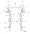
まず、図1及び図2に示すように、キャブトラック1は、エンジンルーム3、及び車室5を含むキャビン7と、キャビン7の車両前後方向後方にある荷台9とを備え、このキャビン7及び荷台9は、所定のラダーフレーム11に取り付けられている。このラダーフレーム11は、所定の間隔を隔てて設けられた2本のサイドフレーム13を、複数のクロスメンバ15で連結して構成される。
First, as shown in FIGS. 1 and 2, the cab truck 1 includes a cabin 7 including an engine room 3 and a vehicle compartment 5, and a loading platform 9 at the rear of the cabin 7 in the vehicle front-rear direction. The loading platform 9 is attached to a predetermined
サイドフレーム13は、前輪21の車両前方から後輪23の車両後方まで車両前後方向に延び、その軸線に沿ってサスペンションタワー25と、サスペンションタワー25の前後に設けられたサスペンションアーム取付用ブラケット27と、キャビン7を支持するためのキャブマウントブラケット29,31,33と、荷台9を支持するための荷台マウントブラケット35,37とが設けられている。このサイドフレーム13は、前輪21近傍に、所定の方向に屈曲した屈曲部41を有する。この屈曲部41は、サイドフレーム13を車両前後方向の軸線に対して傾斜させて形成されている。具体的には、サイドフレーム13は、屈曲部41において車両の前方から後方に向かって車幅方向外方に傾斜し、且つ下方に傾斜している。これにより、車室5下側のサイドフレーム13間の幅が、前輪の位置でのサイドフレーム13間の幅よりも広く、且つ車室5下側のサイドフレーム13の高さ位置が、前輪21の位置でのサイドフレーム13の高さ位置よりも低くなっている。これにより、サイドフレーム13によって安定してキャビン7を支持することができ、且つ車室5の高さを確保することができるようになっている。
The
次に、図3に示すように、サイドフレーム13は、車幅方向内方に開口したコ字状断面のアウタパネル51と、車幅方向外方に開口したコ字状断面のインナパネル53とを有する。そしてサイドフレーム13は、アウタパネル51とインナパネル53の一部が重複するよう両者を接合して形成されており、閉断面を形成するようになっている。また、インナパネル53の内壁には、車両前後方向に延びるレインフォースメント55,57が取り付けられている。このレインフォースメント55,57は、インナパネル53の内壁に取り付けられており、サイドフレーム13の車幅方向の曲げ剛性を高めるようになっている。
Next, as shown in FIG. 3, the
また、サイドフレーム13の車両前側及び中央部には、キャビン7をサイドフレーム13に取り付けるための複数対のキャブマウントブラケット29,31,33が接合されており(図2参照)、これらキャブマウントブラケット29,31,33は、前輪21よりも車両前側、屈曲部41、及び車室5よりも車両後側にそれぞれ設けられている。本実施形態にかかる自動車のフレーム構造は、屈曲部41に設けられたキャブマウントブラケット31によってサイドフレーム13のせん断変形を防止するものであり、以下では、屈曲部41に設けられたキャブマウントブラケット31の構成について詳細に説明をする。
Further, a plurality of pairs of
図4は本発明の実施形態にかかる自動車のフレーム構造の車両前方の底面図であり、図5は図4のA−A´断面を下側から見た断面斜視図である。また、図6は車幅方向外方から見たキャブマウントブラケット31の側面図であり、図7はキャブマウントブラケット31の底面図であり、図8は自動車のフレーム構造の車両前方の底面図である。
先ず、図4及び図5に示すように、キャブマウントブラケット31は、車両前後方向に延びるサイドフレーム13の前部に接合されており、その車両後方には、クロスメンバ15が設けられている。
FIG. 4 is a bottom view of the front side of the vehicle frame structure of the automobile according to the embodiment of the present invention, and FIG. 5 is a cross-sectional perspective view of the AA ′ cross section of FIG. 6 is a side view of the
First, as shown in FIGS. 4 and 5, the
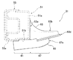
次に、図6から図8に示すように、キャブマウントブラケット31は、その上部がアウタパネル51の車幅方向外側の側面51aに固定されて、車幅方向外方に延びるようになっている。さらにキャブマウントブラケット31は、その下部に車幅方向内方に延びる延設部分61を有する。そして、この延設部分61は、インナパネル53の下面53aに固定されており、キャブマウントブラケット31は、アウタパネル51の側面51aとインナパネル53の下面を連結して、インナパネル53を下側から支持するようになっている。そしてこのキャブマウントブラケット31は、上側部材63と、下側部材65を互いに接合して形成されており、キャブマウントブラケット31を複数の部材で形成することにより、キャブマウントブラケット31を屈曲部41に取り付けるときの位置合わせを容易にすることができる。
Next, as shown in FIGS. 6 to 8, the
上側部材63は、車幅方向外方から見たときに下方に開口した略コ字形状を有する。そして、この上側部材63の車幅方向内方側端部63aも同様に略コ字形状断面を有し、アウタパネル51の側面51aに固定される。そして上側部材63は、アウタパネル51の側面51aから、車幅方向外方に延びる。そして、上側部材63の車幅方向中央部には水平面63bが形成されている。この水平面63bには、キャビン7を取り付けるときに使用するブッシュ(図示せず)が挿入される穴63cが設けられている。
The
下側部材65は、車幅方向内方に延びる延設部分61と、この延設部分61よりも車幅方向外方に形成され上側部材61と接合されるようになっている外方端部分67とによって構成される。
延設部分61は、アウタパネル51の側面51a付近から、インナパネル53の下面53aまで延びており、アウタパネル51の下面51b、及びインナパネル53の下面53aと接合されている。また、延設部分61は、その車両前後方向のそれぞれの端部に、一対の突部71を備える。この突部71は、下方に突出しており、延設部分61の車幅方向内側端部まで延びている。このように延設部分61に突部71を設けることにより、延設部分61の車幅方向の屈曲強度が増す。また、突部71の間には、突部71によって規定され車幅方向に延びる溝73が形成されており、この溝73の底部から突部表面までの距離は、車幅方向内方に向かって長くなるようになっている。
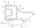
また、外方端部分67の車両前後方向垂直断面は、上方に開口したコ字形状とされ、アウタパネル51の側面51a付近から、車幅方向外方に向かって延びており、その端部67aが、上側部材63の車幅方向外側端部63dよりも車幅方向内側に位置する。また、外方端部分67の車両前後方向の壁部67b,67cは、それぞれ上側部材63の車両前後方向内壁63e,63fに接合されており、上側部材63と外方端部分67は、閉断面を形成するようになっている。また、外方端部分67の車幅方向外方の端部67aは、車幅方向内方に湾曲したU字形状に切り欠かれている。端部67aをU字形状とするとともに溝73の底部から突部71頂部までの距離を外方に向けて短くすることにより、ブッシュの装着を容易としつつ、上側部材63から端部67aの前後方向に伝達された力を分散させることができる。
The
The extending
Further, the vehicle front-rear direction vertical cross section of the
次に、図7及び図8に示すように、上記のようなキャブマウントブラケット31は、その上部にある上側部材63が、アウタパネル51の側面51aに接合され、その下部にある下側部材65が、車幅方向内方に延びてアウタパネル51の下面51b、及びインナパネル53の下面53aに接合される。そして図7及び図8は、キャブマウントブラケット31が屈曲部41の下面に接合されおり、その車両後方には、車幅方向内方に延びるクロスメンバ15が設けられているのを示している。キャブマウントブラケット31の接合位置は、屈曲部41及びキャビン7の車室5の位置を考慮して決定される。すなわち上述のように屈曲部41は、車室5の高さを確保するために設けられているので、車室5の前部は屈曲部41の周辺に位置するようになる。そしてこのキャブマウントブラケット31は、車室5の前部を支持するような位置に配置され、図7に示すように屈曲部41に設けられてもよく、又は車室5の前部の位置に応じて屈曲部41の車両前後方向の位置に設けられてもよい。
Next, as shown in FIGS. 7 and 8, the
次に、図9、及び図10を参照して、本発明の実施形態による自動車のフレーム構造の作用を説明する。ここで、図9は、従来の自動車のフレーム構造のサイドフレーム101及びこのサイドフレーム101の屈曲部に取り付けられたキャブマウントブラケット103を示す車幅方向断面図であり、図10は、本実施形態にかかる自動車のフレーム構造の車幅方向断面図である。
Next, with reference to FIG. 9 and FIG. 10, the effect | action of the frame structure of the motor vehicle by embodiment of this invention is demonstrated. Here, FIG. 9 is a cross-sectional view in the vehicle width direction showing a
図9の状態(a)は、既存のフレーム構造のサイドフレーム101の通常の状態を示す。そしてこのフレーム構造の自動車が前突すると、サイドフレーム101の車両前後方向に圧縮力が作用する。そしてサイドフレーム101が圧縮されると、インナパネル105とアウタパネル107を接合して形成されている閉断面にせん断力が発生する。そしてこのときインナパネル105とアウタパネル107の接合部周辺に応力が集中して、図9の状態(b)に示すように、インナパネル105とアウタパネル107を接合して形成された閉断面がねじれ、インナパネル105が下方に歪むように変形する。
The state (a) in FIG. 9 shows a normal state of the
次に、図10に示すように、本実施形態にかかる自動車のフレーム構造では、インナパネル53とアウタパネル51によって形成されている閉断面にせん断力が発生して、インナパネル53が下方に変形しようとしても、インナパネル53の下面53aのアウタパネル51との接合部位よりも車幅方向内側の部位が、下側部材65によって支持されているため、閉断面の変形が抑制される。そして、下側部材65は、アウタパネル51の下面51b、及び上側部材63を介してアウタパネル51の側面51aに連結されているため、インナパネル53によって下方に押されても、下側部材65の脱落を抑制できる。また、下側部材65がインナパネル53の下面53aによって下方に押されても、下側部材65の延設部分61に突部71が設けられているため、下側部材65が車幅方向に対してせん断変形するのを抑制できるようになっている。
Next, as shown in FIG. 10, in the automobile frame structure according to the present embodiment, a shearing force is generated in the closed cross section formed by the
尚、本実施形態では、キャブマウントブラケット31は、屈曲部41周辺に設けられることとしたが、キャブマウントブラケット31の接合位置を、以下のようにすることで、更にサイドフレーム13の変形を防止することができる。
In the present embodiment, the
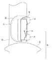
図11は、本実施形態にかかる自動車のフレーム構造の屈曲部41周辺を車幅方向外側から見た側面図である。図11に示すように、キャブマウントブラケット31の車両前方側端部が、サイドフレーム13の屈曲点Fよりも車両前方でサイドフレーム13に接合されていることが好ましい。ここでいう屈曲点Fとは、車両後方に向けて下側に傾斜したサイドフレーム13の下面が平坦になる箇所である。
FIG. 11 is a side view of the periphery of the
このキャブマウントブラケット31が屈曲点Fよりも車両前方に位置するようなフレーム構造によれば、自動車の前突時に前輪21が後方に押されると、この前輪21がその車両後方に設けられたキャブマウントブラケット31に接触し、キャブマウントブラケット31も車両後方に押される。そしてキャブマウントブラケット31が車両後方に押されると、サイドフレーム13の屈曲点Fよりも前方にあるキャブマウントブラケット31の車両前方側端部が、インナパネル53の下面53aを押し上げることとなる。そしてキャブマウントブラケット31がインナパネル53の下面53aを押し上げることにより、サイドフレーム13のせん断変形をさらに抑制することができる。
According to the frame structure in which the
次に、本発明の実施形態にかかる自動車のフレーム構造の変形例について、図12乃至図14を参照して説明する。ここで、図12は、変形例にかかるキャブマウントブラケットの底面図である。 Next, modified examples of the frame structure of the automobile according to the embodiment of the present invention will be described with reference to FIGS. Here, FIG. 12 is a bottom view of the cab mount bracket according to the modification.
図12に示すように、キャブマウントブラケット81の延設部分83の幅は、車幅方向内方に向かって狭まるようになっており、同様に突部85もキャブマウントブラケット81の内側に曲がって延びるようになっている。これにより、キャブマウントブラケット81の車幅方向内側端部81aの車両前後方向の長さは、中央部の車両前後方向の長さよりも短くなる。
As shown in FIG. 12, the width of the extended
図13は、変形例にかかる自動車のフレーム構造の車両前方の底面図であり、さらに図14は、図13のB−B´断面を下側からみた断面斜視図である。図13及び図14に示すように、上述のキャブマウントブラケット81は、屈曲部41周辺のサイドフレーム13の下面にそれぞれ設けられている。そしてサイドフレーム13の間には、これらサイドフレーム13を連結するクロスメンバ91が設けられている。
FIG. 13 is a bottom view of the front side of a vehicle frame structure according to a modified example, and FIG. 14 is a cross-sectional perspective view of the BB ′ cross section of FIG. 13 viewed from below. As shown in FIGS. 13 and 14, the
クロスメンバ91は、車幅方向端部にそれぞれ、切り欠き部93を備えており、インナパネル13の下面に接合されたときに、キャブマウントブラケット81の車幅方向内側端部81aを跨ぐようになっている。そしてキャブマウントブラケット81がインナパネル53の下面に取り付けられたときに、キャブマウントブラケット81の車幅方向内側端部81aが、クロスメンバ91の切り欠き部93に配置されるようになり、キャブマウントブラケット81とクロスメンバが重ならないようになっている。
The
このように、キャブマウントブラケット81の車幅方向内側端部81aの車両前後方向の長さを短くし、且つクロスメンバ91の端部に切り欠き部93を設けることによって、キャブマウントブラケット81が設けられている屈曲部41周辺にクロスメンバ91を容易に配置して、屈曲部41の強度を補強することができる。
Thus, the
7 キャビン
13 サイドフレーム
31,81 キャブマウントブラケット
41 屈曲部
51 アウタパネル
53 インナパネル
61 延設部分
63 上側部材
65 下側部材
71 突部
91 クロスメンバ
7
Claims (7)
前記サイドフレームの前部の車幅方向外側に設けられキャビンを支持するキャブマウントブラケットとを有し、
前記キャブマウントブラケットは、その上部が前記アウタパネルの側面に接合され車幅方向外方に延び、その下部が前記アウタパネルの側面よりも車幅方向内方に延びた延設部分を有しこの延設部分が前記インナパネルの下面に接合されていること特徴とする自動車のフレーム構造。 A pair of side frames spaced apart in the vehicle width direction and extending in the vehicle front-rear direction, an outer panel having a U-shaped cross section opened inward in the vehicle width direction and an inner panel having a U-shaped cross section opened outward in the vehicle width direction A side frame having a closed cross section formed by joining
A cab mount bracket that is provided outside the front side of the side frame in the vehicle width direction and supports the cabin;
The upper part of the cab mount bracket is joined to the side surface of the outer panel and extends outward in the vehicle width direction, and the lower part of the cab mount bracket has an extending portion extending inward in the vehicle width direction from the side surface of the outer panel. A frame structure for an automobile, wherein a portion is joined to a lower surface of the inner panel.
前記キャブマウントブラケットは、その上部が前記アウタパネルの側面に接合された上側部材、その下部が車幅方向内側に延設部分が設けられた下側部材として形成され、これらの上側部材と下側部材とが接合されて形成されると共に、この延設部分が前記アウタパネルとインナパネルの下面に接合されている請求項1に記載の自動車のフレーム構造。 The side frame includes a bent portion that is bent so as to be inclined in at least one of a vehicle width direction and a vertical direction around the cab mount bracket,
The upper part of the cab mount bracket is formed as an upper member joined to the side surface of the outer panel, and the lower part thereof is formed as a lower member provided with an extending portion on the inner side in the vehicle width direction. The vehicle frame structure according to claim 1, wherein the extended portion is joined to the lower surface of the outer panel and the inner panel.
前記上側部材の車両前後方向垂直断面は、下側部材の開口上に架設されて前記下側部材と閉断面を形成するように下方に開口したコ字形状とされ、
さらに前記上側部材は、前記下側部材の車幅方向外側端部分から前記延設部分にかけて車幅方向に延びるようになっている請求項2又は請求項3に記載の自動車のフレーム構造。 The vehicle front-rear direction vertical cross section of the vehicle width direction outer side end portion of the lower member of the cab mount bracket has a substantially U-shape opened upward,
The vertical cross section of the upper member in the vehicle front-rear direction is a U-shape that extends over the opening of the lower member and opens downward so as to form a closed cross section with the lower member.
4. The automobile frame structure according to claim 2, wherein the upper member extends in the vehicle width direction from the outer end portion of the lower member in the vehicle width direction to the extended portion. 5.
さらに、車幅方向に延びて前記一対のサイドフレームを連結するクロスメンバを備え、このクロスメンバが、前記キャブマウントブラケットの延設部分の車幅方向内側端部を跨いで前記インナパネルの下面に接合されている請求項1乃至請求項4の何れか1項に記載の自動車のフレーム構造。 The width of the extended portion of the cab mount bracket is formed so as to narrow toward the inside in the vehicle width direction,
The cross member further includes a cross member that extends in the vehicle width direction and connects the pair of side frames, and the cross member straddles the inner end portion in the vehicle width direction of the extending portion of the cab mount bracket on the lower surface of the inner panel. The automobile frame structure according to any one of claims 1 to 4, wherein the frame structure is joined.
前記キャブマウントブラケットは、前記屈曲部にある前記インナパネルの下面を支持するようになっている請求項2乃至請求項6の何れか1項に記載の自動車のフレーム構造。 The bent portion of the side frame is bent toward the rear lower side in the vicinity of the front wheel,
7. The automobile frame structure according to claim 2, wherein the cab mount bracket supports a lower surface of the inner panel at the bent portion. 8.
Priority Applications (5)
| Application Number | Priority Date | Filing Date | Title |
|---|---|---|---|
| JP2008213099A JP5354154B2 (en) | 2008-08-21 | 2008-08-21 | Automobile frame structure |
| US12/473,898 US8002064B2 (en) | 2008-08-21 | 2009-05-28 | Frame structure of automotive vehicle |
| DE102009035219.8A DE102009035219B4 (en) | 2008-08-21 | 2009-07-29 | Frame structure of a vehicle and method for providing the same |
| CN2009101709300A CN101654119B (en) | 2008-08-21 | 2009-08-21 | Frame structure of automotive vehicle |
| US12/708,489 US8141904B2 (en) | 2008-08-21 | 2010-02-18 | Energy absorbing structure for a vehicle |
Applications Claiming Priority (1)
| Application Number | Priority Date | Filing Date | Title |
|---|---|---|---|
| JP2008213099A JP5354154B2 (en) | 2008-08-21 | 2008-08-21 | Automobile frame structure |
Publications (2)
| Publication Number | Publication Date |
|---|---|
| JP2010047114A true JP2010047114A (en) | 2010-03-04 |
| JP5354154B2 JP5354154B2 (en) | 2013-11-27 |
Family
ID=41695675
Family Applications (1)
| Application Number | Title | Priority Date | Filing Date |
|---|---|---|---|
| JP2008213099A Expired - Fee Related JP5354154B2 (en) | 2008-08-21 | 2008-08-21 | Automobile frame structure |
Country Status (4)
| Country | Link |
|---|---|
| US (1) | US8002064B2 (en) |
| JP (1) | JP5354154B2 (en) |
| CN (1) | CN101654119B (en) |
| DE (1) | DE102009035219B4 (en) |
Cited By (6)
| Publication number | Priority date | Publication date | Assignee | Title |
|---|---|---|---|---|
| JP2015166207A (en) * | 2014-03-03 | 2015-09-24 | トヨタ自動車株式会社 | Skeletal structure of vehicle |
| JP2015214197A (en) * | 2014-05-08 | 2015-12-03 | トヨタ自動車株式会社 | Vehicle front part structure |
| JP2019534205A (en) * | 2016-10-31 | 2019-11-28 | アピコ アマタ カンパニー リミテッド | Strengthening parts for connecting points on the chassis and their manufacture |
| CN113635979A (en) * | 2021-08-21 | 2021-11-12 | 重庆长安汽车股份有限公司 | Packing box mounting structure and vehicle |
| WO2023100341A1 (en) * | 2021-12-03 | 2023-06-08 | 三菱自動車工業株式会社 | Front structure of body frame |
| JP7381327B2 (en) | 2019-12-20 | 2023-11-15 | 日野自動車株式会社 | vehicle frame structure |
Families Citing this family (28)
| Publication number | Priority date | Publication date | Assignee | Title |
|---|---|---|---|---|
| US8141904B2 (en) * | 2008-08-21 | 2012-03-27 | Ford Global Technologies, Llc | Energy absorbing structure for a vehicle |
| JP5354154B2 (en) | 2008-08-21 | 2013-11-27 | マツダ株式会社 | Automobile frame structure |
| US8807597B2 (en) * | 2010-02-18 | 2014-08-19 | Ford Global Technologies, Llc | Frontal collision energy absorption structure for vehicle |
| DE202011000731U1 (en) * | 2011-03-30 | 2011-06-01 | Schmitz Cargobull AG, 48341 | Profile carrier for a vehicle chassis and utility vehicle chassis with such a profile carrier |
| JP5827032B2 (en) * | 2011-04-28 | 2015-12-02 | 株式会社ヨロズ | Cross member |
| CN103213621B (en) * | 2013-04-28 | 2016-02-03 | 长城汽车股份有限公司 | Vehicle body second supports and has the vehicle that this vehicle body second supports |
| CN103407494B (en) * | 2013-08-27 | 2016-01-27 | 长城汽车股份有限公司 | For the longeron of vehicle frame |
| JP5983583B2 (en) * | 2013-11-01 | 2016-08-31 | トヨタ自動車株式会社 | Vehicle skeleton structure |
| ES2731221T3 (en) * | 2014-04-01 | 2019-11-14 | Guangdong Huachan Research Institute Of Intelligent Transp System Co Ltd | Electric vehicle frame system |
| JP6449562B2 (en) * | 2014-06-13 | 2019-01-09 | トヨタ自動車株式会社 | Vehicle frame structure |
| US9757825B2 (en) * | 2014-06-27 | 2017-09-12 | Ford Global Technologies, Llc | Pickup box front sill, floor and headboard construction |
| KR101569355B1 (en) | 2014-10-28 | 2015-11-17 | 주식회사 포스코 | Upper arm and shock absorber mounting bracket and frame for automobile having the same |
| US9423093B1 (en) | 2014-12-19 | 2016-08-23 | Allyn Clark | Under-vehicle ground effect system |
| JP6172179B2 (en) * | 2015-02-25 | 2017-08-02 | マツダ株式会社 | Car side body structure |
| CN106005018B (en) * | 2015-03-27 | 2018-03-20 | 本田技研工业株式会社 | Vehicle body front structure |
| JP6485259B2 (en) * | 2015-07-06 | 2019-03-20 | トヨタ自動車株式会社 | Joint structure for vehicle frame |
| US9718353B2 (en) * | 2015-09-01 | 2017-08-01 | Ronald Scott Bandy | Chassis for independent suspension system |
| CN105365887B (en) * | 2015-12-16 | 2017-10-10 | 上汽通用五菱汽车股份有限公司 | A kind of three cavity multilayers welding front longitudinal |
| KR101855766B1 (en) * | 2016-04-28 | 2018-05-09 | 현대자동차 주식회사 | Reinforcement unit for engine room |
| US10011303B1 (en) * | 2017-06-05 | 2018-07-03 | GM Global Technology Operations LLC | Vehicle frame, body, and cabin structure assembly |
| JP6816698B2 (en) * | 2017-10-16 | 2021-01-20 | トヨタ自動車株式会社 | Side rail and side rail manufacturing method |
| JP6852641B2 (en) * | 2017-10-16 | 2021-03-31 | トヨタ自動車株式会社 | Manufacturing method of side rails and side rails |
| JP6624182B2 (en) * | 2017-11-16 | 2019-12-25 | スズキ株式会社 | Body structure |
| CN111976834A (en) * | 2019-05-22 | 2020-11-24 | 上海汽车集团股份有限公司 | Vehicle and front longitudinal beam thereof |
| JP2021004005A (en) * | 2019-06-27 | 2021-01-14 | いすゞ自動車株式会社 | Ladder frame for vehicle |
| JP7205404B2 (en) * | 2019-06-28 | 2023-01-17 | トヨタ自動車株式会社 | vehicle structure |
| JP6923035B1 (en) * | 2020-04-02 | 2021-08-18 | トヨタ自動車株式会社 | Vehicle skeleton structure |
| US11648989B2 (en) | 2021-02-19 | 2023-05-16 | Bendix Commercial Vehicle Systems Llc | Heavy-duty vehicle frame rail clamp on mounting bracket, and method of installing the same |
Citations (5)
| Publication number | Priority date | Publication date | Assignee | Title |
|---|---|---|---|---|
| JPS6246779A (en) * | 1985-08-26 | 1987-02-28 | Nissan Motor Co Ltd | Cab mount structure of car |
| JPS6422530U (en) * | 1987-07-30 | 1989-02-06 | ||
| JP2003252235A (en) * | 2002-03-05 | 2003-09-10 | Isuzu Motors Ltd | Connection structure of side member to cross member |
| JP2005306329A (en) * | 2004-04-26 | 2005-11-04 | Mitsubishi Motors Corp | Towing hook mounting structure |
| JP2008094135A (en) * | 2006-10-06 | 2008-04-24 | Toyota Motor Corp | Vehicular body supporting structure |
Family Cites Families (44)
| Publication number | Priority date | Publication date | Assignee | Title |
|---|---|---|---|---|
| US1552702A (en) * | 1921-03-02 | 1925-09-08 | Clarence R Irish | Automobile body support |
| US1514981A (en) * | 1923-07-09 | 1924-11-11 | Merville Blaise Francois Felix | Mounting of motor-car bodies on their chassis |
| US1652357A (en) * | 1923-11-06 | 1927-12-13 | William D Harper | Vehicle-body support |
| US1737177A (en) * | 1928-01-24 | 1929-11-26 | Int Motor Co | Mounting for bus bodies |
| US1982105A (en) * | 1933-05-26 | 1934-11-27 | Studebaker Corp | Vehicle construction |
| US2136122A (en) * | 1935-03-21 | 1938-11-08 | Midland Steel Prod Co | Chassis side rail |
| US2384096A (en) * | 1940-11-14 | 1945-09-04 | Nash Kelvinator Corp | Body mount |
| US2403145A (en) * | 1941-07-17 | 1946-07-02 | Budd Edward G Mfg Co | Wheel and motor suspension, especially for automobiles |
| NL68015C (en) * | 1946-02-14 | |||
| US2769656A (en) * | 1953-07-31 | 1956-11-06 | Int Harvester Co | Vehicle cab and front end mounting |
| US3149856A (en) * | 1959-08-17 | 1964-09-22 | Smith Corp A O | Motor vehicle having increased ground clearance level floor space |
| US3101809A (en) * | 1961-10-06 | 1963-08-27 | Int Harvester Co | Vehicle cab mounting means |
| US3554596A (en) * | 1969-02-06 | 1971-01-12 | White Motor Corp | Cab support |
| DE2757784C2 (en) * | 1976-12-27 | 1984-12-13 | Toyota Shatai K.K., Kariya, Aichi | Device for suppressing vibrations in a vehicle |
| US5149132A (en) * | 1991-02-04 | 1992-09-22 | A. O. Smith Corporation | Split rear truck frame |
| JPH0589159U (en) * | 1992-05-09 | 1993-12-03 | マツダ株式会社 | Vehicle suspension cross member structure |
| JPH0699849A (en) * | 1992-09-18 | 1994-04-12 | Nissan Motor Co Ltd | Automobile body mounting structure |
| JP2842102B2 (en) | 1992-10-16 | 1998-12-24 | 三菱自動車エンジニアリング株式会社 | Frame reinforcement structure |
| JPH06329049A (en) * | 1993-05-21 | 1994-11-29 | Nissan Motor Co Ltd | Cab mounting part structure for frame type vehicle |
| US5561902A (en) * | 1994-09-28 | 1996-10-08 | Cosma International Inc. | Method of manufacturing a ladder frame assembly for a motor vehicle |
| JP3381444B2 (en) * | 1995-03-03 | 2003-02-24 | 日産自動車株式会社 | Strength member structure of vehicle body |
| US5915727A (en) * | 1996-05-31 | 1999-06-29 | Dana Corporation | Mounting structure for vehicle frame assembly |
| US6428046B1 (en) * | 1997-10-17 | 2002-08-06 | The Budd Company | Front cradle for a vehicle |
| US5897139A (en) * | 1998-02-05 | 1999-04-27 | Chrysler Corporation | Front suspension casting |
| JP2000272537A (en) * | 1999-03-29 | 2000-10-03 | Isuzu Motors Ltd | Safety device against chassis frame collision in vehicle |
| US6439608B1 (en) * | 1999-08-31 | 2002-08-27 | Dana Corporation | Bracket and side rail structure for supporting a steering gear on a vehicle frame assembly |
| US6398262B1 (en) | 2000-09-26 | 2002-06-04 | Dana Corporation | Modular subframe assembly for a motor vehicle |
| US6866295B2 (en) | 2000-12-28 | 2005-03-15 | Dana Corporation | Modular cast independent front suspension subframe |
| JP2002205662A (en) | 2001-01-11 | 2002-07-23 | Toyota Auto Body Co Ltd | Frame structure of cab over type car |
| US6733021B1 (en) * | 2001-10-26 | 2004-05-11 | Dana Corporation | Vehicle subframe mounting |
| DE10158107C1 (en) * | 2001-11-27 | 2003-02-27 | Daimler Chrysler Ag | Modular structure chassis has front part with two side cantilevers and cross bearers |
| DE10219275B4 (en) * | 2002-04-30 | 2009-09-10 | Daimler Ag | Chassis for a commercial vehicle |
| GB0214773D0 (en) * | 2002-06-26 | 2002-08-07 | Ford Global Tech Inc | Vehicle chassis |
| US6733040B1 (en) * | 2002-07-02 | 2004-05-11 | Dana Corporation | Closed channel structural member having internal reinforcement for vehicle body and frame assembly |
| US6866285B1 (en) * | 2003-11-25 | 2005-03-15 | Trailer hitch and draw bar system | |
| CN100482518C (en) * | 2004-10-13 | 2009-04-29 | 日产自动车株式会社 | Body frame structure for automotive vehicle |
| DE102006009300A1 (en) | 2006-03-01 | 2007-09-06 | Daimlerchrysler Ag | Independent wheel suspension for a high-beam axle |
| DE602007006247D1 (en) * | 2006-03-15 | 2010-06-17 | Mazda Motor | Front body of a motor vehicle |
| JP4233053B2 (en) * | 2006-04-27 | 2009-03-04 | 本田技研工業株式会社 | Body front structure |
| US7862085B2 (en) | 2006-11-28 | 2011-01-04 | Gm Global Technologies Operations, Inc. | Three-dimensional vehicle frame |
| US7802816B2 (en) | 2008-05-27 | 2010-09-28 | Honda Motor Company Ltd. | Control arm support brackets and vehicles using same |
| US7762619B2 (en) * | 2008-07-29 | 2010-07-27 | Ford Global Technologies, Llc | Sequential crash hinges in automotive frame rails |
| US8141904B2 (en) * | 2008-08-21 | 2012-03-27 | Ford Global Technologies, Llc | Energy absorbing structure for a vehicle |
| JP5354154B2 (en) | 2008-08-21 | 2013-11-27 | マツダ株式会社 | Automobile frame structure |
-
2008
- 2008-08-21 JP JP2008213099A patent/JP5354154B2/en not_active Expired - Fee Related
-
2009
- 2009-05-28 US US12/473,898 patent/US8002064B2/en active Active
- 2009-07-29 DE DE102009035219.8A patent/DE102009035219B4/en not_active Expired - Fee Related
- 2009-08-21 CN CN2009101709300A patent/CN101654119B/en not_active Expired - Fee Related
Patent Citations (5)
| Publication number | Priority date | Publication date | Assignee | Title |
|---|---|---|---|---|
| JPS6246779A (en) * | 1985-08-26 | 1987-02-28 | Nissan Motor Co Ltd | Cab mount structure of car |
| JPS6422530U (en) * | 1987-07-30 | 1989-02-06 | ||
| JP2003252235A (en) * | 2002-03-05 | 2003-09-10 | Isuzu Motors Ltd | Connection structure of side member to cross member |
| JP2005306329A (en) * | 2004-04-26 | 2005-11-04 | Mitsubishi Motors Corp | Towing hook mounting structure |
| JP2008094135A (en) * | 2006-10-06 | 2008-04-24 | Toyota Motor Corp | Vehicular body supporting structure |
Cited By (8)
| Publication number | Priority date | Publication date | Assignee | Title |
|---|---|---|---|---|
| JP2015166207A (en) * | 2014-03-03 | 2015-09-24 | トヨタ自動車株式会社 | Skeletal structure of vehicle |
| US9394003B2 (en) | 2014-03-03 | 2016-07-19 | Toyota Jidosha Kabushiki Kaisha | Vehicle framework structure |
| JP2015214197A (en) * | 2014-05-08 | 2015-12-03 | トヨタ自動車株式会社 | Vehicle front part structure |
| JP2019534205A (en) * | 2016-10-31 | 2019-11-28 | アピコ アマタ カンパニー リミテッド | Strengthening parts for connecting points on the chassis and their manufacture |
| JP7381327B2 (en) | 2019-12-20 | 2023-11-15 | 日野自動車株式会社 | vehicle frame structure |
| CN113635979A (en) * | 2021-08-21 | 2021-11-12 | 重庆长安汽车股份有限公司 | Packing box mounting structure and vehicle |
| CN113635979B (en) * | 2021-08-21 | 2022-11-04 | 重庆长安汽车股份有限公司 | Packing box mounting structure and vehicle |
| WO2023100341A1 (en) * | 2021-12-03 | 2023-06-08 | 三菱自動車工業株式会社 | Front structure of body frame |
Also Published As
| Publication number | Publication date |
|---|---|
| DE102009035219A8 (en) | 2010-08-12 |
| CN101654119B (en) | 2013-05-08 |
| CN101654119A (en) | 2010-02-24 |
| US8002064B2 (en) | 2011-08-23 |
| JP5354154B2 (en) | 2013-11-27 |
| DE102009035219A1 (en) | 2010-04-08 |
| US20100045072A1 (en) | 2010-02-25 |
| DE102009035219B4 (en) | 2017-11-16 |
Similar Documents
| Publication | Publication Date | Title |
|---|---|---|
| JP5354154B2 (en) | Automobile frame structure | |
| JP4654917B2 (en) | Car body rear structure | |
| JP6090128B2 (en) | Front body structure of the vehicle | |
| CN109204572B (en) | Lower body structure of automobile | |
| JP5352682B2 (en) | Body floor structure | |
| US7644978B2 (en) | Vehicle floor structure for a motor vehicle | |
| US9415808B2 (en) | Vehicle front section structure | |
| JP4919144B2 (en) | Step mounting structure for getting on and off the vehicle | |
| JP2009120140A (en) | Automobile roof structure | |
| JPH0872742A (en) | Car body structure of center pillar bottom part of vehicle | |
| CN108725588B (en) | Vehicle body floor structure | |
| JP2008137483A (en) | Vehicle body front part structure | |
| JP4923406B2 (en) | Body front structure | |
| JP5321334B2 (en) | Vehicle cowl structure | |
| JP6590862B2 (en) | Suspension arm support structure | |
| JP5402010B2 (en) | Lower body structure of the vehicle | |
| JP4133723B2 (en) | Front body structure of automobile | |
| JP2009280106A (en) | Vehicle frame structure | |
| JP2008302911A (en) | Vehicle body structure | |
| JP5000219B2 (en) | Vehicle side sill structure | |
| JP5496727B2 (en) | Front body structure of automobile | |
| JP2008068755A (en) | Mounting structure of car seat belt apparatus | |
| JP6062294B2 (en) | Open car front body structure | |
| JP4798437B2 (en) | Body front structure | |
| JP4204362B2 (en) | Cab deformation prevention structure |
Legal Events
| Date | Code | Title | Description |
|---|---|---|---|
| A621 | Written request for application examination |
Free format text: JAPANESE INTERMEDIATE CODE: A621 Effective date: 20110620 |
|
| A521 | Written amendment |
Free format text: JAPANESE INTERMEDIATE CODE: A523 Effective date: 20120618 |
|
| A131 | Notification of reasons for refusal |
Free format text: JAPANESE INTERMEDIATE CODE: A131 Effective date: 20121025 |
|
| A977 | Report on retrieval |
Free format text: JAPANESE INTERMEDIATE CODE: A971007 Effective date: 20121025 |
|
| A521 | Written amendment |
Free format text: JAPANESE INTERMEDIATE CODE: A523 Effective date: 20121221 |
|
| A131 | Notification of reasons for refusal |
Free format text: JAPANESE INTERMEDIATE CODE: A131 Effective date: 20130410 |
|
| A521 | Written amendment |
Free format text: JAPANESE INTERMEDIATE CODE: A523 Effective date: 20130606 |
|
| TRDD | Decision of grant or rejection written | ||
| A01 | Written decision to grant a patent or to grant a registration (utility model) |
Free format text: JAPANESE INTERMEDIATE CODE: A01 Effective date: 20130731 |
|
| A61 | First payment of annual fees (during grant procedure) |
Free format text: JAPANESE INTERMEDIATE CODE: A61 Effective date: 20130813 |
|
| R150 | Certificate of patent or registration of utility model |
Ref document number: 5354154 Country of ref document: JP Free format text: JAPANESE INTERMEDIATE CODE: R150 Free format text: JAPANESE INTERMEDIATE CODE: R150 |
|
| LAPS | Cancellation because of no payment of annual fees |