JP6082467B2 - Injection valve - Google Patents
Injection valve Download PDFInfo
- Publication number
- JP6082467B2 JP6082467B2 JP2015532342A JP2015532342A JP6082467B2 JP 6082467 B2 JP6082467 B2 JP 6082467B2 JP 2015532342 A JP2015532342 A JP 2015532342A JP 2015532342 A JP2015532342 A JP 2015532342A JP 6082467 B2 JP6082467 B2 JP 6082467B2
- Authority
- JP
- Japan
- Prior art keywords
- stopper
- injection valve
- opposing
- opposing surface
- angle
- Prior art date
- Legal status (The legal status is an assumption and is not a legal conclusion. Google has not performed a legal analysis and makes no representation as to the accuracy of the status listed.)
- Active
Links
- 238000002347 injection Methods 0.000 title claims description 68
- 239000007924 injection Substances 0.000 title claims description 68
- 239000000446 fuel Substances 0.000 claims description 5
- 238000002485 combustion reaction Methods 0.000 claims description 4
- 229960001716 benzalkonium Drugs 0.000 claims 1
- CYDRXTMLKJDRQH-UHFFFAOYSA-N benzododecinium Chemical compound CCCCCCCCCCCC[N+](C)(C)CC1=CC=CC=C1 CYDRXTMLKJDRQH-UHFFFAOYSA-N 0.000 claims 1
- 238000013016 damping Methods 0.000 description 5
- 238000002788 crimping Methods 0.000 description 4
- 230000002238 attenuated effect Effects 0.000 description 3
- 230000007423 decrease Effects 0.000 description 3
- 230000005489 elastic deformation Effects 0.000 description 3
- 230000009471 action Effects 0.000 description 1
- 230000008859 change Effects 0.000 description 1
- 230000001419 dependent effect Effects 0.000 description 1
- 238000004519 manufacturing process Methods 0.000 description 1
- 238000000034 method Methods 0.000 description 1
- 230000008569 process Effects 0.000 description 1
- 230000007704 transition Effects 0.000 description 1
Images


Classifications
-
- F—MECHANICAL ENGINEERING; LIGHTING; HEATING; WEAPONS; BLASTING
- F02—COMBUSTION ENGINES; HOT-GAS OR COMBUSTION-PRODUCT ENGINE PLANTS
- F02M—SUPPLYING COMBUSTION ENGINES IN GENERAL WITH COMBUSTIBLE MIXTURES OR CONSTITUENTS THEREOF
- F02M51/00—Fuel-injection apparatus characterised by being operated electrically
- F02M51/06—Injectors peculiar thereto with means directly operating the valve needle
- F02M51/061—Injectors peculiar thereto with means directly operating the valve needle using electromagnetic operating means
- F02M51/0625—Injectors peculiar thereto with means directly operating the valve needle using electromagnetic operating means characterised by arrangement of mobile armatures
- F02M51/0664—Injectors peculiar thereto with means directly operating the valve needle using electromagnetic operating means characterised by arrangement of mobile armatures having a cylindrically or partly cylindrically shaped armature, e.g. entering the winding; having a plate-shaped or undulated armature entering the winding
- F02M51/0685—Injectors peculiar thereto with means directly operating the valve needle using electromagnetic operating means characterised by arrangement of mobile armatures having a cylindrically or partly cylindrically shaped armature, e.g. entering the winding; having a plate-shaped or undulated armature entering the winding the armature and the valve being allowed to move relatively to each other or not being attached to each other
-
- F—MECHANICAL ENGINEERING; LIGHTING; HEATING; WEAPONS; BLASTING
- F02—COMBUSTION ENGINES; HOT-GAS OR COMBUSTION-PRODUCT ENGINE PLANTS
- F02M—SUPPLYING COMBUSTION ENGINES IN GENERAL WITH COMBUSTIBLE MIXTURES OR CONSTITUENTS THEREOF
- F02M51/00—Fuel-injection apparatus characterised by being operated electrically
- F02M51/06—Injectors peculiar thereto with means directly operating the valve needle
- F02M51/061—Injectors peculiar thereto with means directly operating the valve needle using electromagnetic operating means
- F02M51/0625—Injectors peculiar thereto with means directly operating the valve needle using electromagnetic operating means characterised by arrangement of mobile armatures
- F02M51/0635—Injectors peculiar thereto with means directly operating the valve needle using electromagnetic operating means characterised by arrangement of mobile armatures having a plate-shaped or undulated armature not entering the winding
- F02M51/066—Injectors peculiar thereto with means directly operating the valve needle using electromagnetic operating means characterised by arrangement of mobile armatures having a plate-shaped or undulated armature not entering the winding the armature and the valve being allowed to move relatively to each other or not being attached to each other
-
- F—MECHANICAL ENGINEERING; LIGHTING; HEATING; WEAPONS; BLASTING
- F02—COMBUSTION ENGINES; HOT-GAS OR COMBUSTION-PRODUCT ENGINE PLANTS
- F02M—SUPPLYING COMBUSTION ENGINES IN GENERAL WITH COMBUSTIBLE MIXTURES OR CONSTITUENTS THEREOF
- F02M2200/00—Details of fuel-injection apparatus, not otherwise provided for
- F02M2200/07—Fuel-injection apparatus having means for avoiding sticking of valve or armature, e.g. preventing hydraulic or magnetic sticking of parts
-
- F—MECHANICAL ENGINEERING; LIGHTING; HEATING; WEAPONS; BLASTING
- F02—COMBUSTION ENGINES; HOT-GAS OR COMBUSTION-PRODUCT ENGINE PLANTS
- F02M—SUPPLYING COMBUSTION ENGINES IN GENERAL WITH COMBUSTIBLE MIXTURES OR CONSTITUENTS THEREOF
- F02M2200/00—Details of fuel-injection apparatus, not otherwise provided for
- F02M2200/30—Fuel-injection apparatus having mechanical parts, the movement of which is damped
- F02M2200/306—Fuel-injection apparatus having mechanical parts, the movement of which is damped using mechanical means
Landscapes
- Engineering & Computer Science (AREA)
- Physics & Mathematics (AREA)
- Electromagnetism (AREA)
- Chemical & Material Sciences (AREA)
- Combustion & Propulsion (AREA)
- Mechanical Engineering (AREA)
- General Engineering & Computer Science (AREA)
- Fuel-Injection Apparatus (AREA)
- Magnetically Actuated Valves (AREA)
Description
本発明は、媒体を噴射するための、特に燃料を燃焼室内に噴射するための噴射弁に関する。この場合、噴射プロセスは、通路噴射式または直接噴射式として構成されていてよい。 The present invention relates to an injection valve for injecting a medium, in particular for injecting fuel into a combustion chamber. In this case, the injection process may be configured as a passage injection type or a direct injection type.
従来技術によれば、ガソリンを噴射するための、ニードル弁を備えた弁が開示されており、このニードル弁は、所望の燃料量が適切に燃焼室内に直接供給されるように、アクチュエータ例えば電磁石または圧電調整器によって閉鎖ばねに向かって移動せしめられる。本発明においては、磁石可動子がニードル弁から分離されている噴射弁が考慮される。噴射弁の開放時に、磁石可動子は、ニードル弁に存在する下側のストッパ(第2のストッパ)から迅速に離れて、可動子フリーストロークを迅速に通過し、上側のストッパ(第1のストッパ)に当接して弁を迅速に開放するようにしなければならない。弁への給電が終了すると、ニードル弁は再び閉鎖する。磁石可動子は、ニードル弁が弁座を再び閉鎖した後で、下側のストッパに当接するまでその運動を継続する。可動子は、その非作動位置に再び達するまで、下側のストッパによって何回か跳ね返される。磁石可動子が再びその非作動位置に戻るまでの時間は、連続的に行われる噴射を高い精度で迅速に停止させる弁の能力のために決定的に重要である。一般的な形式で、下側のストッパに、つまりニードル弁における磁石可動子と対応するストッパスリーブとの間に、圧着ギャップが形成されている。この圧着ギャップ内で、噴射しようとする媒体が圧着されるので、閉鎖時に磁石可動子が減衰され、迅速に非作動位置に戻される。しかしながら圧着ギャップは、開放時に運動を減衰することによって、迅速な開放を妨げる。従って、このような圧着ギャップは、妥協案として、磁石可動子が十分迅速に弁を開放し、十分迅速に再び非作動位置に戻されるように、設計されなければならない。 According to the prior art, a valve with a needle valve for injecting gasoline is disclosed, this needle valve being an actuator, for example an electromagnet, so that the desired amount of fuel is appropriately fed directly into the combustion chamber. Alternatively, it is moved toward the closing spring by a piezoelectric adjuster. In the present invention, an injection valve in which the magnet mover is separated from the needle valve is considered. When the injection valve is opened, the magnet mover quickly moves away from the lower stopper (second stopper) existing in the needle valve and quickly passes the mover free stroke, and the upper stopper (first stopper). ) To quickly open the valve. When the power supply to the valve is finished, the needle valve is closed again. After the needle valve closes the valve seat again, the magnet mover continues its movement until it contacts the lower stopper. The mover is rebounded several times by the lower stopper until it reaches its inoperative position again. The time it takes for the magnet mover to return to its non-actuated position again is critical because of the valve's ability to quickly stop a continuous injection with high accuracy. In a general form, a crimping gap is formed in the lower stopper, i.e. between the magnet mover in the needle valve and the corresponding stopper sleeve. Since the medium to be ejected is crimped in the crimp gap, the magnet mover is damped when closed, and quickly returned to the inoperative position. However, the crimp gap prevents rapid opening by attenuating movement upon opening. Therefore, such a crimp gap must be designed so that, as a compromise, the magnet mover opens the valve quickly enough and is returned quickly back to the inoperative position.
請求項1の特徴を有する本発明による噴射弁は、磁石可動子をより良好に減衰し、それによって磁石可動子を、噴射弁の閉鎖時に、従来よりも迅速にその非作動位置へ戻すことができる。それと同時に、本発明によれば、噴射弁の開放時に減衰が低下され、それによって噴射弁がより迅速に開放する。詳しく言えば、これによって、噴射弁の開放時に次の利点が得られる。磁石可動子は、従来よりも迅速にニードル弁から離れ、それによって弁のダイナミックスが高められ、ひいては機能が改善される。開放のために必要な力は減少され、それによって、噴射弁の消費電流、ひいては車両の全エネルギ需要が低下する。従って、車両の燃料消費は低減する。噴射弁の閉鎖時に次の利点が得られる。磁石可動子の運動は、従来よりも強く減衰される。それによって磁石可動子は、従来よりも早期に非作動位置に達し、それによって、短時間で連続する噴射を高い再現精度で停止させることができる。本発明の噴射弁によって、少ない排出有害物質および少ない燃料消費による燃焼を可能にする新たな噴射方式が可能である。噴射弁の閉鎖時における改善された減衰は、磁石可動子のパルスがニードル弁に伝達されることによって発生する騒音を低下させる。これらすべての利点は、出口側に少なくとも1つの噴射口を備えたハウジングと、電磁コイルと、この電磁コイルによって直線運動せしめられる磁石可動子とを有する、本発明の噴射弁によって得られる。さらに、この噴射弁はニードル弁を有している。このニードル弁は、少なくとも1つの噴射口を開閉させるために用いられる。このニードル弁は長手方向軸線に沿って延在していて、直線的に運動可能である。磁石可動子内に貫通孔が形成されている。この貫通孔内にニードル弁が差し込まれている。この場合、磁石可動子は、第1のストッパと第2のストッパとの間で、ニードル弁に対して直線的に可動である。これによって、ダブルマスシステムが得られる。第1のストッパは、磁石可動子の、出口とは反対側に形成されている。例えば第1のストッパは、ニードル弁に設けられたリングによって形成されている。第2のストッパは、磁石可動子の、出口に面した側に形成されている。本発明によれば、第2のストッパは、ストッパ部材と対抗部材とによって形成されている。第2のストッパにおいて、ストッパ部材と対抗部材とが互いに当接し合う。このために、ストッパ部材はストッパ面を有している。対抗部材に、ストッパ面に向き合う対抗面が形成されている。ストッパ面と対抗面とは、第2のストッパにおいて互いにぶつかり合う。ストッパ部材は弾性的に構成されているので、対抗面とストッパ面とがぶつかり合うと、長手方向軸線とストッパ面との間の角度が変化する。特に、ストッパ面は、ストッパ部材と対抗部材とが接触する前後に、対抗部材に向かって傾斜されている。対抗部材とストッパ部材とが互いにぶつかると直ちに、ストッパ部材は弾性的に変形せしめられ、それによってストッパ面と対抗面との間のスペースは縮小する。ストッパ部材が本発明に従って弾性的に構成されていることによって、ストッパ面と対抗面との間の圧着ギャップおよび絞り流は、ストッパ面と対抗面とが互いに接近し合う運動および互いに離れる運動を行う際に変化する。これによって、噴射弁の開閉時における減衰は、非常に精確に調節され得る。 The injection valve according to the invention having the features of claim 1 dampens the magnet mover better so that it can be returned to its inoperative position more quickly than before when the injection valve is closed. it can. At the same time, according to the invention, the damping is reduced when the injector is opened, thereby opening the injector more quickly. Specifically, this provides the following advantages when the injector is opened. The magnet mover moves away from the needle valve more quickly than before, thereby increasing the dynamics of the valve and thus improving its function. The force required for opening is reduced, thereby reducing the current consumption of the injector and thus the total energy demand of the vehicle. Therefore, the fuel consumption of the vehicle is reduced. The following advantages are obtained when the injection valve is closed. The movement of the magnet mover is attenuated more strongly than before. As a result, the magnet mover reaches the non-operating position earlier than in the prior art, whereby it is possible to stop the continuous injection in a short time with high reproducibility. The injection valve of the present invention enables a new injection scheme that allows combustion with low emissions and low fuel consumption. The improved damping when the injection valve is closed reduces the noise generated by the magnet mover pulses being transmitted to the needle valve. All these advantages are obtained by the injection valve of the present invention having a housing with at least one injection port on the outlet side, an electromagnetic coil, and a magnet mover that is linearly moved by the electromagnetic coil. Furthermore, this injection valve has a needle valve. This needle valve is used to open and close at least one injection port. The needle valve extends along the longitudinal axis and is movable linearly. A through hole is formed in the magnet mover. A needle valve is inserted into the through hole. In this case, the magnet mover is linearly movable with respect to the needle valve between the first stopper and the second stopper. This provides a double mass system. The first stopper is formed on the opposite side of the magnet mover from the outlet. For example, the first stopper is formed by a ring provided on the needle valve. The second stopper is formed on the side of the magnet mover facing the outlet. According to the present invention, the second stopper is formed by the stopper member and the counter member. In the second stopper, the stopper member and the opposing member abut each other. For this purpose, the stopper member has a stopper surface. A facing surface facing the stopper surface is formed on the facing member. The stopper surface and the opposing surface collide with each other in the second stopper. Since the stopper member is elastically configured, the angle between the longitudinal axis and the stopper surface changes when the opposing surface and the stopper surface collide. In particular, the stopper surface is inclined toward the opposing member before and after the stopper member and the opposing member contact each other. As soon as the opposing member and the stopper member collide with each other, the stopper member is elastically deformed, thereby reducing the space between the stopper surface and the opposing surface. Due to the stopper member being elastically configured according to the present invention, the crimping gap and the throttle flow between the stopper surface and the opposing surface cause the stopper surface and the opposing surface to move toward and away from each other. Change when. As a result, the damping when the injection valve is opened and closed can be adjusted very precisely.
従属請求項には、本発明の好適な実施態様が記載されている。 The dependent claims contain preferred embodiments of the invention.
好適には、ストッパ部材はニードル弁に堅固に結合されている。相応に、対抗部材が磁石可動子に配置されている。この場合、対抗部材は特に磁石可動子の一体的な構成部分である。最も簡単な場合、対抗面は、ストッパ面に面した、磁石可動子の側面である。選択的な構成によれば、ストッパ部材は磁石可動子に堅固に結合されていてよい。この場合、対抗部材はニードル弁に堅固に結合されている。重要なことは、第2のストッパにおける、互いに向き合う2つの面のうちの少なくとも一方が弾性的に構成されている、ということである。この少なくとも1つの弾性的な面は、本出願の枠内でストッパ面と称呼される。 Preferably, the stopper member is firmly connected to the needle valve. Correspondingly, a counter member is arranged on the magnet mover. In this case, the counter member is in particular an integral part of the magnet mover. In the simplest case, the opposing surface is the side of the magnet mover facing the stopper surface. According to an optional configuration, the stopper member may be firmly coupled to the magnet mover. In this case, the counter member is firmly connected to the needle valve. What is important is that at least one of the two surfaces facing each other in the second stopper is elastically configured. This at least one elastic surface is referred to as a stopper surface within the framework of the present application.
好適には、ストッパ部材または対抗部材は、ニードル弁内に組み込まれている。選択的に、ストッパ部材または対抗部材は磁石可動子内に組み込まれている。 Preferably, the stopper member or the counter member is incorporated in the needle valve. Optionally, the stopper member or the counter member is incorporated in the magnet mover.
さらに好適には、長手方向軸線とストッパ面との間の角度は、ストッパ面と対抗面とが接触しない状態で、少なくとも部分的に90°より小さい。この角度は、ストッパ面の、対抗面に面した側において規定されている。つまり、90°より小さい角度によって規定されて、ストッパ面は対抗面に向かって傾けられている、ということである。この場合、ストッパ面が、相応の角度の部分的な傾斜を有しているだけで、十分である。対抗面がストッパ面に当接している間、ストッパ面は変形されるので、前記角度は拡大する。 More preferably, the angle between the longitudinal axis and the stopper surface is at least partially less than 90 °, with the stopper surface and the opposing surface not in contact. This angle is defined on the side of the stopper surface facing the opposing surface. That is, it is defined by an angle smaller than 90 °, and the stopper surface is inclined toward the opposing surface. In this case, it is sufficient that the stopper surface only has a partial inclination of a corresponding angle. Since the stopper surface is deformed while the opposing surface is in contact with the stopper surface, the angle is expanded.
ストッパ面と対抗面とが互いに離れる際に、つまり噴射弁の開放時に、ストッパ部材は再び緩み、それによって前記角度は再び縮小する。角度の、このような構成によって、噴射弁の開放時に、絞り流だけが磁石可動子の運動を減衰するが、圧着ギャップが磁石可動子の運動を減衰することはない。対抗面とストッパ面とが例えば互いに離れる運動を行うと直ちに、ストッパ部材は緩み、それによってストッパ面が対抗面に向かって傾く。従って、ストッパ面と対抗面とは、もはや互いに平行ではなく、圧着ギャップは存在しない。絞り流だけが、つまり、ストッパ面と対抗面との間の領域から流れ出る、噴射しようとする媒体の流れだけが、磁石可動子の開放運動を減衰する。 When the stopper surface and the opposing surface are separated from each other, that is, when the injection valve is opened, the stopper member loosens again, whereby the angle is reduced again. With such an angular configuration, only the throttle flow attenuates the movement of the magnet mover when the injection valve is opened, but the crimp gap does not attenuate the movement of the magnet mover. As soon as the opposing surface and the stopper surface move away from each other, for example, the stopper member is loosened, whereby the stopper surface is tilted towards the opposing surface. Therefore, the stopper surface and the opposing surface are no longer parallel to each other and there is no crimping gap. Only the throttle flow, that is, the flow of the medium to be jetted out of the region between the stopper surface and the opposing surface, attenuates the opening movement of the magnet mover.
噴射弁の閉鎖時に、ストッパ面と対抗面とは、互いに接近する運動を行う。この場合、最初は、ストッパ面が対抗面に向かって傾いているので、ストッパ面と対抗面との間に、媒体で満たされた比較的大きいスペースが存在している。この運動は、まず絞り流によって減衰され、ストッパ面と対抗面とが互いに当接し合うと、直ちにストッパ面は変形せしめられるので、ストッパ面は対抗面に対して平行に整列する。それによって、磁石可動子の運動を減衰するための圧着ギャップが発生する。つまり、減衰作用は、ストッパ面と対抗面との間の間隔が縮小するにつれて増大する。 When the injection valve is closed, the stopper surface and the opposing surface move toward each other. In this case, since the stopper surface is inclined toward the facing surface at first, a relatively large space filled with the medium exists between the stopper surface and the facing surface. This movement is first attenuated by the throttle flow, and as soon as the stopper surface and the opposing surface come into contact with each other, the stopper surface is immediately deformed, so that the stopper surface is aligned parallel to the opposing surface. Thereby, a crimping gap for attenuating the movement of the magnet mover is generated. In other words, the damping action increases as the distance between the stopper surface and the opposing surface decreases.
特に、前記角度は、ストッパ面と対抗面とが接触しない状態で、最大で89.99°、好適には最大で89.85°である。前述のように、この角度はストッパ面全体に亘って存在しなくてもよい。 In particular, the angle is a maximum of 89.99 °, preferably a maximum of 89.85 ° in a state where the stopper surface and the opposing surface do not contact each other. As described above, this angle may not exist over the entire stopper surface.
さらに、好適には、対抗面とストッパ面とがぶつかることによって、前記角度は、少なくとも0.01°、好適には少なくとも0.15°だけ弾性的に変形せしめられる。特に好適な構成によれば、前記ストッパ面は、ストッパ面と対抗面とが互いに平行に整列されるまで、変形される。 Furthermore, the angle is preferably elastically deformed by at least 0.01 °, preferably at least 0.15 °, by the collision of the opposing surface and the stopper surface. According to a particularly preferred configuration, the stopper surface is deformed until the stopper surface and the opposing surface are aligned parallel to each other.
さらに好適には、ストッパ面が、内側区分と外側区分とに分割されている。この場合、内側区分は、外側区分よりも、長手方向軸線により近い位置にある。特に好適には、ストッパ面は、ニードル弁を取り囲む環状面である。この場合、内側区分は内側の環状面である。外側区分は、内側区分の外側に位置する別の環状面である。前記角度は、ストッパ面と対抗面とが接触しない状態で、内側区分におけるよりも外側区分において、より大きい。このために、好適には、ストッパ面は、長手方向軸線からの距離が大きいほど、対抗面に向かってより大きく傾斜している。 More preferably, the stopper surface is divided into an inner section and an outer section. In this case, the inner section is closer to the longitudinal axis than the outer section. Particularly preferably, the stopper surface is an annular surface surrounding the needle valve. In this case, the inner section is an inner annular surface. The outer section is another annular surface located outside the inner section. The angle is greater in the outer section than in the inner section with the stopper surface and the opposing surface not in contact. For this reason, the stopper surface is preferably inclined more toward the opposing surface as the distance from the longitudinal axis increases.
特に好適には、内側区分は、ストッパ面と対抗面とが接触しない状態で、対抗面に対して平行に構成されている。選択的に、内側区分が対抗面に対して傾斜されているか、または凹状に構成されていてもよい。 Particularly preferably, the inner section is configured parallel to the opposing surface in a state where the stopper surface and the opposing surface do not contact. Optionally, the inner section may be inclined with respect to the facing surface or configured to be concave.
ストッパ部材において、対抗面とは反対側が外側面と称呼される。この外側面は、ストッパ面を変形させるために十分な弾性が与えられるように、相応に成形されているべきである。従って、外側面は、好適には対抗部材に向かって傾斜されているか、または少なくとも部分的に凹状に構成されている。選択的に、外側面はストッパ面に対して部分的に平行であってもよい。この場合、ストッパ部材ができるだけ薄く構成されていて、それによってストッパ面が弾性的に変形できることが、重要である。 In the stopper member, the side opposite to the opposing surface is referred to as the outer surface. This outer surface should be correspondingly shaped so that it is sufficiently elastic to deform the stopper surface. The outer surface is therefore preferably inclined towards the counter member or at least partly concave. Optionally, the outer surface may be partially parallel to the stopper surface. In this case, it is important that the stopper member is configured to be as thin as possible so that the stopper surface can be elastically deformed.
ストッパ部材およびひいてはストッパ面の弾性的な変形可能性を保証するために、好適にはストッパ部材に複数の溝が設けられている。特に好適には、これらの溝は、長手方向軸線を完全に取り囲んで環状に形成されている。 In order to ensure the elastic deformation of the stopper member and thus the stopper surface, the stopper member is preferably provided with a plurality of grooves. Particularly preferably, these grooves are formed in an annular shape completely surrounding the longitudinal axis.
第1のストッパは、好適な形式で、ニードル弁に設けられた段部またはリングによって形成されている。 The first stopper is formed in a suitable manner by a step or ring provided on the needle valve.
以下に、本発明の実施例を添付の図面を参照して詳しく説明する。 Hereinafter, embodiments of the present invention will be described in detail with reference to the accompanying drawings.
以下に図1〜図7を用いて、噴射弁1の第1実施例を説明する。同じ若しくは機能的に同じ構成部分には、すべての実施例において同じ符号が付けられている。 A first embodiment of the injection valve 1 will be described below with reference to FIGS. The same or functionally identical components are labeled with the same reference in all embodiments.
図1は、すべての実施例のための噴射弁1の一般的な構成を示す。噴射弁1は、出口側3に噴射口4を備えたハウジング2を有している。ハウジング2は、電磁コイル5を支持している。ハウジング2内に、ボール7を備えたニードル弁6が長手方向軸線15に沿って配置されている。ボール7は、ハウジング2と共に、噴射口4を開閉するための弁座を形成している。
FIG. 1 shows the general configuration of an injection valve 1 for all embodiments. The injection valve 1 has a
さらに、ハウジング2内に磁石可動子8が設けられていて、この磁石可動子8はばね受け9に結合されている。磁石可動子8の、出口とは反対側で、リング10がニードル弁6に堅固に配置されている。リング10は、磁石可動子8のための第1のストッパを形成する。磁石可動子8の、出口に面した側に、ストッパ部材12が配置されている。このストッパ部材12は、磁石可動子8と共に第2のストッパを形成する。
Further, a
ニードル弁6も磁石可動子8も、長手方向軸線15に沿って直線的に可動である。この場合、磁石可動子8の運動は、第1および第2のストッパによって制限されている。
Both the
磁石可動子8内に、噴射しようとする媒体のための複数の通路16が設けられている。追加的にまたは選択的に、ニードル弁6は中空に構成されていてもよい。
A plurality of
第1のばね11によって、ニードル弁6は出口側3に向かって付勢されている。第2のばね13は、ばね受け9とストッパ部材12との間で、磁石可動子8をやはり出口側3に向かって付勢する。
The
電磁コイル5に給電することによって磁石可動子8は移動せしめられる。磁石可動子8は、第1および第2のストッパを介してニードル弁6を連動する。2つのストッパ間の間隔は、可動子フリーストローク14を規定する。
The
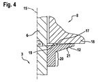
図2は、第1実施例による噴射弁1の詳細を示す。図2には、ストッパ部材12がスリーブ20と一体的に構成されていることが示されている。スリーブ20はニードル弁6に被せ嵌められ、ニードル弁6に堅固に結合されている。磁石可動子8は同時にいわゆる対抗部材18として構成されている。
FIG. 2 shows details of the injection valve 1 according to the first embodiment. FIG. 2 shows that the
対抗部材18に面した、ストッパ部材12の面はストッパ面17と称呼される。対抗部材18に、ストッパ面17に向き合う対抗面19が配置されている。ストッパ部材12の、対抗部材18とは反対側は、外側面21と称呼される。記載された角度αは、ストッパ面17と長手方向軸線15との間に規定されている。この場合、角度αは、対抗部材18に面した、ストッパ面17の側において測定される。
The surface of the
ストッパ部材12およびひいてはストッパ面17も、弾性的に変形可能である。対抗部材18つまり磁石可動子8がストッパ部材12に当接すると、ストッパ部材12は弾性的に変形し、それによって角度αが拡大する。
The
図3は、スリーブ20およびストッパ部材12の詳細を示す。スリーブ20とストッパ部材12とは、長手方向軸線15に対して同軸的な貫通孔28を有している。この貫通孔28内にニードル弁6が差し込まれる。
FIG. 3 shows details of the
第1の高さ25は、長手方向軸線15に対して平行に貫通孔28の上端部からストッパ面17の外側端部まで延びている。ストッパ面17の外側端部は尖端27と称呼される。第2の高さ26は、長手方向軸線15に対して平行なストッパ部材12の寸法を示す。図示の実施例では、ストッパ面17の弾性は、2つの高さ25,26が0より大きいことによって得られる。
The first height 25 extends from the upper end of the through
図4〜図7は、噴射弁の開閉時における動作進行を示す。図4は、電磁コイル5に給電されておらず、磁石可動子8がストッパ部材12上に軽く載っているだけの非作動状態を示す。従って、ストッパ面17は変形されておらず、ストッパ面17は90°より小さい角度αで対抗面19に向かって傾斜されている。
4 to 7 show the progress of the operation when the injection valve is opened and closed. FIG. 4 shows a non-actuated state in which the electromagnetic coil 5 is not supplied with power and the
以下の図面に、噴射しようとする媒体の絞り流が符号29で示されている。ストッパ部材12の破線は、弾性的な変形を示す。
In the following drawings, the throttle flow of the medium to be ejected is indicated by
図5では、電磁コイル5において励磁された磁界によって、磁石可動子8が内極に向かって、図面では上方に引き寄せられる。この場合、ニードル弁6は、磁石可動子8が可動子フリーストローク14を克服して、リング10(第1のストッパ)を介してニードル弁6を連動するまで、弁座内に留まっている。磁石可動子8とニードル弁6との間の相対運動が行われている限り、磁石可動子8とニードル弁6との間、つまりストッパ面17と対抗面18との間に絞り流29が形成される。ストッパ面17と対抗面19との間の絞り流29は、間隔が大きくなるにつれて低下するので、噴射弁は迅速に開放する。図6では、電磁コイル5への電流が遮断されていて、磁界が消滅している。ニードル弁6は座部内に位置していて、磁石可動子8は、リング10における第1のストッパからストッパ部材12における第2のストッパに向かって、その運動を継続する。磁石可動子8とニードル弁6との間の相対運動によって、ストッパ面17と対抗面19との間に再び絞り流29が形成される。絞り流29は、間隔が小さくなるにつれて増大するので、磁石可動子8の運動は次第に減衰される。磁石可動子8がストッパ部材12にぶつかると、つまり対抗面19がストッパ面17にぶつかると、衝撃によってストッパ部材12は弾性的に変形し、ストッパ面17と対抗面19との間に存在する減衰体積は圧着ギャップとなる。この状態は図7に示されている。これによって磁石可動子8の運動は制動される。ストッパ部材12の弾性変形によって、ストッパ面17は対抗面19に対して面平行に整列され、それによって、圧着ギャップによる、磁石可動子運動の減衰は最大化される。
In FIG. 5, the
図8は、第2実施例による噴射弁1の詳細を示す。第2実施例では、ストッパ面17が内側区分23と外側区分24とに分割されている。この場合、内側区分23は、対抗面19と接触しない状態でも、長手方向軸線15に対して垂直に配置され、ひいては対抗面19に対して平行にも配置されている。外側区分24で、ストッパ面17は、対抗面19に向かって角度αの傾斜を有している。
FIG. 8 shows details of the injection valve 1 according to the second embodiment. In the second embodiment, the
外側面21は、対抗面19に対して部分的に平行、かつ部分的に対抗面19に向かって傾斜して構成されている。特に、外側面21は、概ね外側区分24の領域内において対抗面に向かって傾いているので、この個所において、ストッパ部材12の十分な弾性が与えられている。
The
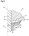
図9は、第3実施例による噴射弁1の詳細を示す。第3実施例において、ストッパ面17は、内側区分23も外側区分24も、対抗面19に向かって傾斜されている。しかしながら、外側区分24の傾斜がより強いので、この個所においてストッパ部材12の、より大きい変形が発生する。
FIG. 9 shows details of the injection valve 1 according to the third embodiment. In the third embodiment, the
図10は、第4実施例による噴射弁1の詳細を示す。第4実施例では、第3実施例と同じくストッパ面17は、内側区分23も外側区分24も対抗面19に向かって傾斜されている。この場合、外側面21は、スリーブ20から対抗面19に向かって同じ大きさの角度で傾斜されている。これによって、特に外側領域内に非常に幅の狭いストッパ部材12が形成され、このストッパ部材12は相応に弾性的に変形可能である。
FIG. 10 shows details of the injection valve 1 according to the fourth embodiment. In the fourth embodiment, the
図11は第5実施例による噴射弁1の詳細を示す。第5実施例では、ストッパ面17は、内側区分23に亘って対抗面19に対して平行に配置されている。外側区分24に亘ってストッパ面17は凹状に形成されている。ストッパ部材12の外側面21も凹状に形成されている。これによって、様々な傾斜間の丸味を付けられた移行部を有する比較的幅の狭いストッパ部材12が形成されるので、確実に機能する弾性が保証される。この場合、角度αは、外側区分24におけるストッパ面17の凹状の構成部における接線と長手方向軸線15とによって規定されている。
FIG. 11 shows details of the injection valve 1 according to the fifth embodiment. In the fifth embodiment, the
図12は、第6実施例による噴射弁1の詳細を示す。第6実施例では、ストッパ部材12の外側面21内に溝が配置されている。この溝22は、特に長手方向軸線15の周りに環状に形成されている。この溝22によって、ストッパ部材12は相応に弱められており、従って所望の弾性が与えられている。
FIG. 12 shows details of the injection valve 1 according to the sixth embodiment. In the sixth embodiment, a groove is disposed in the
図13には、第7実施例による噴射弁1の一部が示されている。第7実施例において、やはりストッパ部材12の弾性を調節するための溝22が図示されている。第7実施例では、溝22は、長手方向軸線15に対して平行なストッパ部材12の面に配置されている。これによって、溝22は尖端27およびストッパ面17の非常に近くに達しているので、この実施例では、全ストッパ部材12ではなく、上側の区分だけが変形される。
FIG. 13 shows a part of the injection valve 1 according to the seventh embodiment. In the seventh embodiment, a
様々な実施例によって、ストッパ部材12の可能な幾何学形状が示されている。これらの実施例において、ストッパ面17は通常は楔形に形成されている。何故ならば、楔形状は、寸法定めおよび製造が簡単だからである。勿論、図示の実施例の組み合わせも可能である。従って、相応の形状深さおよび数の、図12および図13に示した溝22を、別の実施例に使用してもよい。さらに、図9,10および11に示した外側面21を、すべての実施例に適合させることも可能である。異なる実施例のストッパ面17の、様々な角度と、凹状の構成とを互いに組み合わせることができる。さらに、十分な弾性が保証されている限りは、ストッパ部材12のすべての別の凹状および凸状の形状が可能である。溝22のための別の横断面形状は、例えば三角形または楕円形である。剛性を相応に適合させるために、各ストッパ部材12にそれぞれ1つ以上の溝22を設けてもよい。この実施例は、回転対称的であるが中空ではないニードル弁6を示す。同じように良好に、本発明は、中空および/または非回転対称的なニードル弁6に使用することができる。ストッパ面17または対抗面19も、回転対称的に構成される必要はない。
According to various embodiments, possible geometries of the
図示したすべての実施例は、ストッパ面17およびストッパ部材12がニードル弁6と堅固に結合された実施例を示す。それに応じて、磁石可動子8はこれらの実施例において対抗面19を備えた対抗部材18として規定されている。同じように良好に、弾性的なストッパ部材12が磁石可動子8に堅固に結合された構成も可能である。その場合は、対抗部材18はニードル弁6に堅固に結合される。対抗面19は、本発明の最も簡単な構成では、平らで硬い面である。同じように良好に、このような対抗面19は所定の傾斜および弾性を有していてもよい。
All of the embodiments illustrated show an embodiment in which the
1 噴射弁
2 ハウジング
3 出口側
4 噴射口
5 電磁コイル
6 ニードル弁
7 ボール
8 磁石可動子
9 ばね受け
10 リング、第1のストッパ
11 第1のばね
12 ストッパ部材、第2のストッパ
13 第2のばね
14 可動子フリーストローク
15 長手方向軸線
16 通路
17 ストッパ面
18 対抗部材
19 対抗面
20 スリーブ
21 外側面
22 溝
23 内側区分
24 外側区分
25 第1の高さ
26 第2の高さ
27 尖端
28 貫通孔
29 絞り流
DESCRIPTION OF SYMBOLS 1
Claims (11)
出口側(3)に少なくとも1つの噴射口(4)を備えたハウジング(2)と、
電磁コイル(5)と、
前記電磁コイル(5)によって直線運動せしめられる磁石可動子(8)と、
長手方向軸線(15)に沿って直線運動せしめられ、かつ前記磁石可動子(8)を貫通して突き出す、前記噴射口(4)を開閉させるためのニードル弁(6)と、
を有しており、
前記磁石可動子(8)が第1のストッパと第2のストッパとの間で、前記ニードル弁(6)に対して直線運動せしめられ、
前記第2のストッパが、ストッパ面(17)を備えたストッパ部材(12)によって形成されていて、該ストッパ部材(12)が該ストッパ面(17)に向き合う対抗面(19)を備えた対抗部材(18)を受けることで、前記磁石可動子(8)の前記ニードル弁(6)に対する直線運動が規定され、
前記ストッパ部材(12)が弾性的に構成されていて、それによって前記対抗面(19)が前記ストッパ面(17)に当接する際に、前記長手方向軸線(15)と前記ストッパ面(17)との間の角度(α)が変化し、
前記電磁コイル(5)が励磁された時又は直後に、前記磁石可動子(8)が、前記対抗面(19)と前記ストッパ面(17)との接触が完全に解放されつつ、前記第1のストッパに向かう方向に移動する、
噴射弁。 In the injection valve (1) for injecting the medium,
A housing (2) with at least one injection port (4) on the outlet side (3);
An electromagnetic coil (5);
A magnet mover (8) that is linearly moved by the electromagnetic coil (5);
A needle valve (6) for opening and closing the injection port (4), which is linearly moved along a longitudinal axis (15) and protrudes through the magnet mover (8);
Have
The magnet mover (8) is linearly moved with respect to the needle valve (6) between the first stopper and the second stopper,
The second stopper, the stopper member (12) having a stopper surface (17) thus be formed, the stopper member (12) is provided with a counter surface (19) facing to the stopper surface (17) By receiving the counter member (18), a linear motion of the magnet mover (8) relative to the needle valve (6) is defined ,
When the stopper member (12) is elastically configured so that the opposing surface (19) contacts the stopper surface (17), the longitudinal axis (15) and the stopper surface (17) The angle (α) between and the
When the electromagnetic coil (5) is excited or immediately after the magnet mover (8), the contact between the opposing surface (19) and the stopper surface (17) is completely released, and the first Move in the direction toward the stopper ,
Injection valve.
請求項1に記載の噴射弁。 Said stopper member (12) has been coupled to the needle valve (6), and wherein the benzalkonium said counter member (18) has been engaged sintered the magnet armature (8),
The injection valve according to claim 1.
請求項1または2に記載の噴射弁。 In said angle (alpha) is a state where the stopper surface (17) and said opposing surface (19) and does not contact between the longitudinal axis (15) and said stopper surface (17), at least partially 90 Less than °, the angle (α) is defined on the side of the stopper surface (17) facing the opposing surface (19),
The injection valve according to claim 1 or 2.
請求項3に記載の噴射弁。 The angle (α) is a maximum of 89.99 ° in a state where the stopper surface (17) and the opposing surface (19) are not in contact with each other,
The injection valve according to claim 3.
請求項1から4のいずれか1項に記載の噴射弁。 Wherein by opposing surfaces (19) abuts on the stopper surface (17), said angle (alpha), characterized in that it is deformed at least only the 0.01 ° elastically,
The injection valve according to any one of claims 1 to 4.
請求項1から5のいずれか1項に記載の噴射弁。 The stopper surface (17) is divided into an inner section (23) and an outer section (24), the inner section (23) being more longitudinal than the outer section (24). And the angle (α) is greater in the outer section (24) than in the inner section (23) with the stopper surface (17) and the opposing surface (19) not in contact. Smaller, characterized in that the angle (α) is defined on the side of the stopper surface (17) facing the opposing surface (19) ,
The injection valve according to any one of claims 1 to 5.
請求項6に記載の噴射弁。 The inner section (23) is parallel to the opposing surface (19) or in contact with the opposing surface (19), with the stopper surface (17) and the opposing surface (19) not in contact. wherein the or is inclined against, or is concave,
The injection valve according to claim 6.
請求項1から7のいずれか1項に記載の噴射弁。 Before SL stopper member (12), opposite side of the opposing surface relative to the said stop surface (17) (19) (21) is inclined with respect to the at least partially the stopper surface (17) And / or at least partly parallel to the stopper surface (17) and / or at least partly concave.
The injection valve according to any one of claims 1 to 7.
請求項1から8のいずれか1項に記載の噴射弁。 The stopper member (12), characterized in that it comprises at least one ring-shaped groove (22),
The injection valve according to any one of claims 1 to 8.
請求項1から9のいずれか1項に記載の噴射弁。 The first stopper is formed by a ring (10) or a step provided in the needle valve (6),
The injection valve according to any one of claims 1 to 9.
請求項1から10のいずれか1項に記載の噴射弁。
The injection valve is an injection valve for injecting fuel into a combustion chamber,
The injection valve according to any one of claims 1 to 10.
Applications Claiming Priority (2)
| Application Number | Priority Date | Filing Date | Title |
|---|---|---|---|
| DE102012217322.6A DE102012217322A1 (en) | 2012-09-25 | 2012-09-25 | Injector |
| PCT/EP2013/065812 WO2014048609A1 (en) | 2012-09-25 | 2013-07-26 | Injection valve |
Publications (2)
| Publication Number | Publication Date |
|---|---|
| JP2015529306A JP2015529306A (en) | 2015-10-05 |
| JP6082467B2 true JP6082467B2 (en) | 2017-02-15 |
Family
ID=48906245
Family Applications (1)
| Application Number | Title | Priority Date | Filing Date |
|---|---|---|---|
| JP2015532342A Active JP6082467B2 (en) | 2012-09-25 | 2013-07-26 | Injection valve |
Country Status (6)
| Country | Link |
|---|---|
| US (1) | US9546630B2 (en) |
| EP (1) | EP2901004B1 (en) |
| JP (1) | JP6082467B2 (en) |
| KR (1) | KR102110114B1 (en) |
| DE (1) | DE102012217322A1 (en) |
| WO (1) | WO2014048609A1 (en) |
Families Citing this family (16)
| Publication number | Priority date | Publication date | Assignee | Title |
|---|---|---|---|---|
| DE102015209395A1 (en) * | 2015-05-22 | 2016-11-24 | Robert Bosch Gmbh | fuel injector |
| DE102015213221A1 (en) * | 2015-07-15 | 2017-01-19 | Robert Bosch Gmbh | Valve for metering a fluid |
| DE102015213216A1 (en) * | 2015-07-15 | 2017-01-19 | Robert Bosch Gmbh | Valve for metering a fluid |
| JP6468109B2 (en) * | 2015-07-21 | 2019-02-13 | 株式会社デンソー | Fuel injection valve |
| DE102015215537A1 (en) | 2015-08-14 | 2017-02-16 | Robert Bosch Gmbh | Valve for metering a fluid |
| KR102119988B1 (en) * | 2015-10-15 | 2020-06-17 | 콘티넨탈 오토모티브 게엠베하 | Fuel injection valve with anti-skid device, combustion engine and vehicle |
| DE102016211454A1 (en) * | 2016-06-27 | 2017-12-28 | Robert Bosch Gmbh | Arrangement with a valve for metering a fluid |
| DE102017207273A1 (en) * | 2016-06-30 | 2018-01-04 | Robert Bosch Gmbh | Valve for metering a fluid |
| DE102016220326A1 (en) * | 2016-10-18 | 2018-04-19 | Robert Bosch Gmbh | Valve for metering a gaseous or liquid fuel |
| DE102016223536A1 (en) * | 2016-11-28 | 2018-05-30 | Robert Bosch Gmbh | Valve for dosing a gas |
| DE102016225768A1 (en) | 2016-12-21 | 2018-06-21 | Robert Bosch Gmbh | A fuel injector and method of operating a fuel injector |
| DE102016225769A1 (en) * | 2016-12-21 | 2018-06-21 | Robert Bosch Gmbh | Valve for metering a fluid |
| CN106894930A (en) * | 2017-02-24 | 2017-06-27 | 中国第汽车股份有限公司 | A kind of swirling flow ejector |
| DE102018200364A1 (en) * | 2018-01-11 | 2019-07-11 | Robert Bosch Gmbh | Valve for metering a fluid |
| DE102018201951A1 (en) * | 2018-02-08 | 2019-08-08 | Robert Bosch Gmbh | Valve for metering a fluid |
| JP7338155B2 (en) * | 2019-01-08 | 2023-09-05 | 株式会社デンソー | fuel injector |
Family Cites Families (10)
| Publication number | Priority date | Publication date | Assignee | Title |
|---|---|---|---|---|
| DE19849210A1 (en) * | 1998-10-26 | 2000-04-27 | Bosch Gmbh Robert | Fuel injection valve for internal combustion engine fuel injection system has armature movable between two stops, damping spring arranged between second stop and armature |
| JP2000265919A (en) | 1999-03-16 | 2000-09-26 | Bosch Automotive Systems Corp | Solenoid fuel injection valve |
| DE19927900A1 (en) * | 1999-06-18 | 2000-12-21 | Bosch Gmbh Robert | Fuel injection valve for direct injection IC engine has movement of armature limited by opposing stops attached to valve needle one of which is provided by spring element |
| DE19950761A1 (en) * | 1999-10-21 | 2001-04-26 | Bosch Gmbh Robert | Fuel injection valve has supporting ring between elastomeric ring and armature that supports elastomeric ring axially near opening of fuel channel in armature and radially on shoulder |
| US6454191B1 (en) * | 2000-01-10 | 2002-09-24 | Delphi Technologies, Inc. | Electromagnetic fuel injector dampening device |
| DE10108974A1 (en) * | 2001-02-24 | 2002-09-05 | Bosch Gmbh Robert | Fuel injector |
| EP1576277A1 (en) * | 2002-12-13 | 2005-09-21 | Robert Bosch Gmbh | Bounce-free magnetic actuator for injection valves |
| JP2007224811A (en) | 2006-02-23 | 2007-09-06 | Denso Corp | Injector |
| JP5048617B2 (en) * | 2008-09-17 | 2012-10-17 | 日立オートモティブシステムズ株式会社 | Fuel injection valve for internal combustion engine |
| DE102012203161A1 (en) * | 2012-02-29 | 2013-08-29 | Robert Bosch Gmbh | Injector |
-
2012
- 2012-09-25 DE DE102012217322.6A patent/DE102012217322A1/en not_active Withdrawn
-
2013
- 2013-07-26 US US14/429,466 patent/US9546630B2/en active Active
- 2013-07-26 WO PCT/EP2013/065812 patent/WO2014048609A1/en active Application Filing
- 2013-07-26 EP EP13742624.3A patent/EP2901004B1/en active Active
- 2013-07-26 JP JP2015532342A patent/JP6082467B2/en active Active
- 2013-07-26 KR KR1020157007403A patent/KR102110114B1/en active IP Right Grant
Also Published As
| Publication number | Publication date |
|---|---|
| EP2901004B1 (en) | 2017-03-29 |
| EP2901004A1 (en) | 2015-08-05 |
| DE102012217322A1 (en) | 2014-06-12 |
| US20150247479A1 (en) | 2015-09-03 |
| JP2015529306A (en) | 2015-10-05 |
| KR20150056789A (en) | 2015-05-27 |
| WO2014048609A1 (en) | 2014-04-03 |
| KR102110114B1 (en) | 2020-05-14 |
| US9546630B2 (en) | 2017-01-17 |
Similar Documents
| Publication | Publication Date | Title |
|---|---|---|
| JP6082467B2 (en) | Injection valve | |
| KR101223851B1 (en) | Fuel injection system with high repeatability and stability of operation for an internal-combustion engine | |
| JP4935882B2 (en) | Fuel injection valve | |
| EP1602821B1 (en) | Fuel injection valve | |
| EP3006720A1 (en) | Fuel injection valve | |
| US20130075501A1 (en) | Fuel injector | |
| JP6355765B2 (en) | Fuel injection valve | |
| JP2006097659A (en) | Fuel injection valve | |
| KR101820829B1 (en) | Solenoid valve for high pressure having guide structure | |
| CN105221296B (en) | Gas injector for injecting gaseous fuel | |
| JP5838107B2 (en) | Fuel injection valve | |
| US20130206872A1 (en) | Fuel injector | |
| JP4129689B2 (en) | Fuel injection valve | |
| US20190277236A1 (en) | Fuel injection valve and fuel injection system | |
| US10330062B2 (en) | Injector for injecting fluid | |
| CN111566337A (en) | Valve for metering fluids | |
| US20180195477A1 (en) | Valve for metering a fluid | |
| KR101581304B1 (en) | Valve for Flow Control | |
| JP2005171845A (en) | Electromagnetic drive device and fuel injection valve using the same | |
| KR20180072573A (en) | Valve for metering a fluid | |
| US11629678B2 (en) | Fuel injection valve and method for assembling same | |
| KR102706035B1 (en) | Valve for metering a fluid | |
| JP6224754B2 (en) | Electromagnetic fuel injection valve for in-cylinder injection | |
| KR102196142B1 (en) | Valve assembly and injection valve for injection valve | |
| KR20150134517A (en) | Valve for Flow Control having Double Shock Absorbing Structure |
Legal Events
| Date | Code | Title | Description |
|---|---|---|---|
| A521 | Request for written amendment filed |
Free format text: JAPANESE INTERMEDIATE CODE: A523 Effective date: 20150318 |
|
| A621 | Written request for application examination |
Free format text: JAPANESE INTERMEDIATE CODE: A621 Effective date: 20150318 |
|
| A131 | Notification of reasons for refusal |
Free format text: JAPANESE INTERMEDIATE CODE: A131 Effective date: 20160325 |
|
| A601 | Written request for extension of time |
Free format text: JAPANESE INTERMEDIATE CODE: A601 Effective date: 20160608 |
|
| A521 | Request for written amendment filed |
Free format text: JAPANESE INTERMEDIATE CODE: A523 Effective date: 20160825 |
|
| TRDD | Decision of grant or rejection written | ||
| A01 | Written decision to grant a patent or to grant a registration (utility model) |
Free format text: JAPANESE INTERMEDIATE CODE: A01 Effective date: 20161226 |
|
| A61 | First payment of annual fees (during grant procedure) |
Free format text: JAPANESE INTERMEDIATE CODE: A61 Effective date: 20170120 |
|
| R150 | Certificate of patent or registration of utility model |
Ref document number: 6082467 Country of ref document: JP Free format text: JAPANESE INTERMEDIATE CODE: R150 |
|
| R250 | Receipt of annual fees |
Free format text: JAPANESE INTERMEDIATE CODE: R250 |
|
| R250 | Receipt of annual fees |
Free format text: JAPANESE INTERMEDIATE CODE: R250 |
|
| R250 | Receipt of annual fees |
Free format text: JAPANESE INTERMEDIATE CODE: R250 |
|
| R250 | Receipt of annual fees |
Free format text: JAPANESE INTERMEDIATE CODE: R250 |
|
| R250 | Receipt of annual fees |
Free format text: JAPANESE INTERMEDIATE CODE: R250 |