JP6078054B2 - Heat transfer device with reduced height - Google Patents
Heat transfer device with reduced height Download PDFInfo
- Publication number
- JP6078054B2 JP6078054B2 JP2014513482A JP2014513482A JP6078054B2 JP 6078054 B2 JP6078054 B2 JP 6078054B2 JP 2014513482 A JP2014513482 A JP 2014513482A JP 2014513482 A JP2014513482 A JP 2014513482A JP 6078054 B2 JP6078054 B2 JP 6078054B2
- Authority
- JP
- Japan
- Prior art keywords
- heat transfer
- condenser
- transfer device
- transfer fluid
- chamber
- Prior art date
- Legal status (The legal status is an assumption and is not a legal conclusion. Google has not performed a legal analysis and makes no representation as to the accuracy of the status listed.)
- Expired - Fee Related
Links
Images


Classifications
-
- H—ELECTRICITY
- H01—ELECTRIC ELEMENTS
- H01L—SEMICONDUCTOR DEVICES NOT COVERED BY CLASS H10
- H01L23/00—Details of semiconductor or other solid state devices
- H01L23/34—Arrangements for cooling, heating, ventilating or temperature compensation ; Temperature sensing arrangements
- H01L23/42—Fillings or auxiliary members in containers or encapsulations selected or arranged to facilitate heating or cooling
- H01L23/427—Cooling by change of state, e.g. use of heat pipes
-
- F—MECHANICAL ENGINEERING; LIGHTING; HEATING; WEAPONS; BLASTING
- F25—REFRIGERATION OR COOLING; COMBINED HEATING AND REFRIGERATION SYSTEMS; HEAT PUMP SYSTEMS; MANUFACTURE OR STORAGE OF ICE; LIQUEFACTION SOLIDIFICATION OF GASES
- F25B—REFRIGERATION MACHINES, PLANTS OR SYSTEMS; COMBINED HEATING AND REFRIGERATION SYSTEMS; HEAT PUMP SYSTEMS
- F25B39/00—Evaporators; Condensers
- F25B39/04—Condensers
-
- H—ELECTRICITY
- H05—ELECTRIC TECHNIQUES NOT OTHERWISE PROVIDED FOR
- H05K—PRINTED CIRCUITS; CASINGS OR CONSTRUCTIONAL DETAILS OF ELECTRIC APPARATUS; MANUFACTURE OF ASSEMBLAGES OF ELECTRICAL COMPONENTS
- H05K7/00—Constructional details common to different types of electric apparatus
- H05K7/20—Modifications to facilitate cooling, ventilating, or heating
- H05K7/2029—Modifications to facilitate cooling, ventilating, or heating using a liquid coolant with phase change in electronic enclosures
- H05K7/20318—Condensers
-
- H—ELECTRICITY
- H05—ELECTRIC TECHNIQUES NOT OTHERWISE PROVIDED FOR
- H05K—PRINTED CIRCUITS; CASINGS OR CONSTRUCTIONAL DETAILS OF ELECTRIC APPARATUS; MANUFACTURE OF ASSEMBLAGES OF ELECTRICAL COMPONENTS
- H05K7/00—Constructional details common to different types of electric apparatus
- H05K7/20—Modifications to facilitate cooling, ventilating, or heating
- H05K7/2029—Modifications to facilitate cooling, ventilating, or heating using a liquid coolant with phase change in electronic enclosures
- H05K7/20336—Heat pipes, e.g. wicks or capillary pumps
-
- H—ELECTRICITY
- H01—ELECTRIC ELEMENTS
- H01L—SEMICONDUCTOR DEVICES NOT COVERED BY CLASS H10
- H01L2924/00—Indexing scheme for arrangements or methods for connecting or disconnecting semiconductor or solid-state bodies as covered by H01L24/00
- H01L2924/0001—Technical content checked by a classifier
- H01L2924/0002—Not covered by any one of groups H01L24/00, H01L24/00 and H01L2224/00
Description
1.発明の分野
本発明は、少なくとも1つの蒸発器と、少なくとも1つの凝縮器と、冷却流体によって物体を間接的に冷却するのに用いるために蒸発器および凝縮器を接続する1つまたは複数の流体導管とを有する閉ループ流体冷却システム等の熱伝達装置と、より詳細には、冷却流体を、コンパクトな環境で冷却される物体と間接的に熱接触するように導く、高さが減少した熱伝達装置とに関する。
1. FIELD OF THE INVENTION The present invention relates to at least one evaporator, at least one condenser, and one or more fluids that connect the evaporator and the condenser for use in indirectly cooling an object with a cooling fluid. Heat transfer device, such as a closed loop fluid cooling system, having a conduit, and more particularly reduced heat transfer that directs the cooling fluid into indirect thermal contact with an object to be cooled in a compact environment Relating to the device.
2.関連技術の説明
受動閉ループ二相流体冷却システムは、限定なしにコンピュータチップ等、過度の熱を発生する物体を冷却するために使用される周知の熱伝達装置である。受動という用語は、冷却流体を循環させるためにいかなる機械化されたポンプも使用しないシステムを意味するように意図されている。流体を受動システムにおいて循環させる目的は、熱が加えられる際の流体の浮力変化および相変化に由来する。蒸発器は、通常、冷却される物体と熱接触するように配置され、液体形態の冷却流体は、液体を冷却される実際の物体から分離する面を通過する。このように、流体が決して物体と直接接触することなく、流体と物体との間で熱を伝達することができる。流体に熱を加えることにより、流体の少なくとも一部が気化する。その後、気体は凝縮器に運ばれる。気体が液体状態に再凝縮する際に熱が放出される。凝縮された液体は蒸発器に戻され、この気化−凝縮サイクルは繰り返す。図1aは、こうした従来技術による凝縮器100を示し、図1bはその詳細を示す。従来技術による凝縮器は、通常、円形断面のチューブ102かまたは楕円形あるいは矩形断面を近似する平坦チューブを使用して、凝縮面を提供する。これらのチューブは、通常、それらの長手方向軸を垂直にして配置される。これらのチューブの外周に適合するように寸法が決められた開口部を備える複数の冷却フィン104が、水平に配置されている。図1の従来技術による凝縮器100では、空気冷却フィン104の間に凝縮器チューブが散在しており、したがって、空気冷却フィンおよび凝縮器チューブは液体ヘッダタンク106の上方かつ気体ヘッダタンク108の下方の同じ垂直領域を占有する。気体導管110が加熱気体を気体ヘッダタンク108に導き、凝縮物戻りライン112が凝縮液114を貯蔵器116に戻す。
2. Description of Related Art A passive closed-loop two-phase fluid cooling system is a well-known heat transfer device used to cool objects that generate excessive heat, such as, without limitation, computer chips. The term passive is intended to mean a system that does not use any mechanized pump to circulate the cooling fluid. The purpose of circulating the fluid in the passive system stems from fluid buoyancy changes and phase changes when heat is applied. The evaporator is usually placed in thermal contact with the object to be cooled, and the liquid form of the cooling fluid passes through a surface that separates the liquid from the actual object to be cooled. In this way, heat can be transferred between the fluid and the object without the fluid being in direct contact with the object. By applying heat to the fluid, at least a portion of the fluid is vaporized. The gas is then carried to the condenser. Heat is released as the gas recondenses to a liquid state. The condensed liquid is returned to the evaporator and this vaporization-condensation cycle is repeated. FIG. 1a shows such a
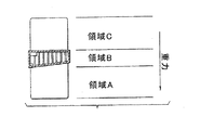
したがって、この従来技術による構成では、空気冷却フィン104のすべてが、凝縮流体(凝縮物114)用の収集箇所の上方、特に液体ヘッダタンク106の上方に位置していることが必要である。これは、従来技術による凝縮器の唯一最大の限界である。従来技術による凝縮器のこの限界を、図1を、本発明を示す図2と比較することによって最もよく示すことができる。図2では、空気冷却フィン118が凝縮器チャンバの領域の上方および下方に位置していることが分かる。図2は、凝縮器チャンバ120の領域の上方および下方の両方の空気冷却フィン118を示すが、空気冷却フィン118を、凝縮器チャンバ120の上方または下方のいずれかに配置することができることが理解されるべきである。空気冷却フィン118の間に凝縮器フィン(凝縮器120内、図2には示さず)が散在していない。これは、凝縮器フィンがそれらの間に冷却空気を通す必要がないため、凝縮器フィンを、従来技術の設計のように互いから水平に離れるように間隔を空ける必要がないことを意味する。これは、さらに、本発明の凝縮器フィンは、従来技術の設計よりそれらの垂直軸に沿ってより短いが、それらの水平方向の間隔がより近いことにより、より多くのフィンを使用することができ、したがって従来技術の設計と実質的に等しい総凝縮物表面積が可能になることを意味する。本発明を、従来技術の設計に実質的に等しい総空気冷却フィン領域を提供するように同様に構成することができる。本発明の重要な利点は、凝縮流体(凝縮液114)用の収集箇所が、従来技術による設計のものより実質的に高い位置にあるということである。本発明のこの重要な利点、すなわち凝縮物表面積および凝縮液用の収集箇所を利用可能な空間内で高くかつ蒸発器構成要素の高さより十分上方に配置することができることは、図4の実施形態において最も明らかである。再び図1を参照すると、貯蔵器内の液体の高さ(RH)と凝縮器内の流体の高さ(CH)との差は、重力水頭と呼ばれることもある重力高さ(GH)である。図に示すように、図2のGH−2は、図1のGH−1より実質的に大きい。各設計が凝縮物を凝縮器から貯蔵器に戻すことができることは、それらのそれぞれの重力高さGH−1およびGH−2に直接結び付いている。所与の利用可能な高さ(AH)に対して、従来技術による設計および本発明の両方を、空気冷却フィン面積および内部凝縮器表面積が実質的に等しいように構成することができる場合、本発明は、そのGHの方が高いためにより高い熱負荷で動作することができる。これは、凝縮物戻りの質量輸送速度が達成可能な熱伝達の最大量に直接関連しているためである。
Thus, this prior art configuration requires that all of the
従来技術の設計と比較して本発明の利点をさらに説明するために、再び図3を参照する。図3は、本発明と同じ重量高さ(GH−2)を提供するように構成された従来技術型の設計を示す。図3に示すように、この構成により、凝縮器の下方に使用することができない領域122があるため、空気冷却フィンおよび凝縮器チューブのための垂直方向の空間が実質的に小さくなる。空気冷却フィン面積および凝縮器チューブ面積の低減により、この構成は本発明より劣るものになる。
To further illustrate the advantages of the present invention compared to the prior art design, reference is again made to FIG. FIG. 3 shows a prior art type design configured to provide the same weight height (GH-2) as the present invention. As shown in FIG. 3, this configuration substantially reduces the vertical space for the air cooling fins and the condenser tube because there is an
上述した理由により、本発明は、利用可能な高さ(AH)が比較的低いことを必要とする用途、すなわち「薄型」設計において、従来技術による設計の凝縮器と比較してより高い熱負荷を伝達することができる。 For the reasons described above, the present invention provides a higher heat load in applications that require a relatively low available height (AH), i.e., a "thin" design, compared to condensers of prior art designs. Can be transmitted.
薄型を達成するように方向が変えられた従来技術型の凝縮器の例があるが、これらは、通常、別の著しい設計考慮事項を犠牲にして薄型を達成する。 There are examples of prior art condensers that have been redirected to achieve low thickness, but these typically achieve low thickness at the expense of another significant design consideration.
たとえば、米国特許第7,422,052号は、実質的に水平に配置された凝縮器構成要素を備えた薄型冷却システムを開示している。この凝縮器は、従来技術による垂直の、すなわち直立した凝縮器に概して類似しているが、依然として浅く傾斜していながら水平面により近いように角度が付けられていることを除く。これにより、高さが減少する利益は、実質的に幅が増加することを犠牲にして得られる。 For example, US Pat. No. 7,422,052 discloses a thin cooling system with condenser components arranged substantially horizontally. The condenser is generally similar to a vertical or upright condenser according to the prior art, except that it is angled to be closer to the horizontal plane while still being shallowly inclined. This provides the benefit of decreasing height at the expense of substantially increasing width.
米国特許第7,231,961号もまた、薄型冷却システムを開示している。この参考文献は、凝縮器を「狭い内部チャネルを有する長いチャンバ」として明記している。このチャンバは、その「長い」寸法が水平面に対して実質的に平行に向けられるように向けられ、水平面は、冷却される装置が取り付けられる面、たとえば冷却されるチップ/プロセッサを支持する回路基板の面を意味するものと解釈される。このチャンバの1つの側面(実質的に垂直な外面)は、空気冷却フィンで埋められている。このチャンバの長さ、幅および高さを定義する、列挙されている寸法範囲に基づいて、チャンバを、単に、従来技術による凝縮器に関して上述した凝縮器チューブの多くに非常に類似する、単一凝縮器チューブと述べることができる。この場合、単一凝縮器チューブは、その長手方向軸を垂直ではなく水平にして配置される。したがって、この設計は、単に凝縮器チューブを水平構成で配置することにより、垂直方向の薄型を達成する。これは、明らかに重力高さを犠牲にして行われる。この限界は、第5段、第12〜19行に明示的に列挙されている。
「通常、熱サイフォンの凝縮器は、重力を利用して凝縮器から蒸発器に液体を強制的に送るために、蒸発器の上にまたは蒸発器より高い位置に配置される。この配置は、利用可能な高さが厳しく制限される空間では不可能である。凝縮器の一部が蒸発器より高い位置であるかまたはその逆も可能であるが、凝縮器および蒸発器は、本発明では互いにおよそ水平である。」
US Pat. No. 7,231,961 also discloses a thin cooling system. This reference specifies the condenser as “a long chamber with a narrow internal channel”. The chamber is oriented so that its “long” dimension is oriented substantially parallel to the horizontal plane, the horizontal plane being the surface on which the device to be cooled is mounted, eg, the circuit board that supports the cooled chip / processor Is taken to mean One side of the chamber (substantially vertical outer surface) is filled with air cooling fins. Based on the listed dimension ranges that define the length, width and height of this chamber, the chamber is simply a single, very similar to many of the condenser tubes described above with respect to prior art condensers. It can be described as a condenser tube. In this case, the single condenser tube is arranged with its longitudinal axis horizontal rather than vertical. Therefore, this design achieves vertical thinness simply by placing the condenser tubes in a horizontal configuration. This is obviously done at the expense of gravity. This limit is explicitly listed in the fifth row, lines 12-19.
“Typically, the thermosyphon condenser is placed on top of or above the evaporator to force the liquid from the condenser to the evaporator using gravity. This is not possible in spaces where the available height is severely limited, part of the condenser can be higher than the evaporator or vice versa, but the condenser and evaporator are They are approximately horizontal to each other. "
この従来技術による設計では、凝縮器の内部容積の著しい部分が、流れない液体によって占有される必要がある、ということも示唆されるべきである。 It should also be suggested that in this prior art design, a significant portion of the internal volume of the condenser needs to be occupied by non-flowing liquid.
これは、流れない液体の中に埋め込まれた凝縮器表面で凝縮が発生することができないという点で凝縮器の性能に対する周知の限界、すなわち多くの場合「凝縮器のフラッディング」と呼ばれる状況を表す。 This represents a well-known limit to condenser performance in that condensation cannot occur on a condenser surface embedded in a non-flowing liquid, a situation often referred to as “condenser flooding” .
したがって、凝縮器は一般に周知でありかつ広く使用されているが、凝縮器を、より効率的に、したがってより競争力があり、費用対効果が大きくかつ有用にすることが引き続き必要とされている。特に、凝縮物の移送のための適切な重力高さと結合された適切な内部凝縮器表面積を提供しながら、非常にコンパクトな環境で物体を冷却するために使用することができる凝縮器を提供することが有用である。 Thus, although condensers are generally well known and widely used, there continues to be a need to make condensers more efficient, and therefore more competitive, cost effective and useful. . In particular, it provides a condenser that can be used to cool an object in a very compact environment while providing a suitable internal condenser surface area combined with a suitable gravity height for condensate transfer. It is useful.
したがって、本発明の目的は、コンピュータチップ等、過熱する傾向がある場合がある物体の効率的かつ有効な冷却を可能にする熱伝達装置を提供することである。 Accordingly, it is an object of the present invention to provide a heat transfer device that enables efficient and effective cooling of objects that may tend to overheat, such as computer chips.
本発明のさらなる目的は、垂直方向のゆとりすなわち上部の余裕が限られている用途で使用される、高さが減少した改善された熱伝達装置を提供することである。 It is a further object of the present invention to provide an improved heat transfer device with reduced height for use in applications where vertical clearance or top margin is limited.
本発明のこれらの目的および他の目的にしたがって、加熱された熱伝達流体を気体から液体に凝縮する実質的に垂直な凝縮器フィンを有するチャンバを備える熱伝達装置が提供される。チャンバは、気体を受け取る入口と、凝縮流体をその液体状態で貯蔵器に戻す出口とを有している。入口および出口はともに、貯蔵器内の液体熱伝達流体の高さより高い高さに配置されている。凝縮面を提供する垂直凝縮器フィンは、入口と出口との間の垂直空間に実質的に配置されている。この配置の利点は、凝縮物が蒸発器に重力によって戻るために、利用可能な垂直高さのより広い部分が残される、ということである。この配置により、同様に、液体を凝縮器構成要素内に押し込む(それが発生した場合、凝縮器のいずれかの部分が動作不能になる)ことのマイナスの結果なしに、液体戻りラインにおいて液体の高さの大幅な変化が可能になる。この構造により、装置は、優れた凝縮性能を達成し、全体的に減少した高さを有することができる。さらに、この構造により、装置は、チャンバの深さがチャンバの内部の高さより大きい、全体的に減少した高さを有することができる。 In accordance with these and other objects of the present invention, a heat transfer device is provided comprising a chamber having substantially vertical condenser fins that condense heated heat transfer fluid from gas to liquid. The chamber has an inlet for receiving gas and an outlet for returning condensed fluid in its liquid state to the reservoir. Both the inlet and outlet are located at a height higher than the height of the liquid heat transfer fluid in the reservoir. Vertical condenser fins that provide a condensing surface are substantially disposed in the vertical space between the inlet and the outlet. The advantage of this arrangement is that the condensate returns to the evaporator by gravity, leaving a wider portion of the available vertical height. This arrangement also applies the liquid in the liquid return line without the negative consequence of pushing liquid into the condenser component (if it occurs, any part of the condenser becomes inoperable). A significant change in height is possible. With this structure, the device can achieve excellent condensation performance and have an overall reduced height. Furthermore, this structure allows the device to have an overall reduced height where the chamber depth is greater than the interior height of the chamber.
本発明の好ましい実施形態では、チャンバ内の凝縮器フィンは、それらの表面に、チャンバ内の有効冷却面を増大させるように溝を有することができる。溝を、設計上の選択事項として、フィンの両側に、一致した対向する対で配置することができ、または両側に交互に互い違いに配置することができる。通常電気機器または電子機器の冷却に適用されるように、チャンバの外面のうちの1つまたは複数に、チャンバと熱連通する複数の空気冷却フィンが取り付けられている。採用される面は、最も典型的には頂面または底面である。最も一般的には複数のフィン(フィンのアレイと呼ばれる場合もある)が採用されるが、単一フィンを同様に使用することができる。空気が、自然対流手段によるかまたは強制対流手段によって1つまたは複数の空気冷却フィンを通過する。自然対流冷却または強制対流冷却に使用される空気冷却フィンを設計し、製造しかつ採用することは、冷却システム設計の技術分野において周知である。1つまたは複数の空気冷却フィンを使用する代りに、チャンバの頂面あるいは底面のいずれかまたは両方に液体冷却板を配置することができる。このように使用される場合、冷却板は、チャンバと熱連通するようにチャンバに固定される。冷却流体が冷却板内を循環する。冷却流体によって提供される冷却により、チャンバ内部の気体が凝縮する。「液体冷却板」という用語は、「液体冷却ヒートシンク」と同義であり、両用語は本技術分野において周知である。液体冷却ヒートシンクの例は、米国特許第5,829,516号に開示されており、参照により本明細書に組み込まれる。 In a preferred embodiment of the present invention, the condenser fins in the chamber can have grooves in their surface to increase the effective cooling surface in the chamber. The grooves can be arranged in matched opposing pairs on either side of the fin as a design choice, or can be alternately staggered on both sides. A plurality of air cooling fins in thermal communication with the chamber are attached to one or more of the outer surfaces of the chamber, as typically applied to the cooling of electrical or electronic equipment. The surface employed is most typically the top surface or the bottom surface. Most commonly, multiple fins (sometimes referred to as an array of fins) are employed, although single fins can be used as well. Air passes through one or more air cooling fins by natural convection means or by forced convection means. The design, manufacture and adoption of air cooling fins used for natural or forced convection cooling is well known in the art of cooling system design. Instead of using one or more air cooling fins, a liquid cooling plate can be placed on either or both the top or bottom of the chamber. When used in this manner, the cold plate is secured to the chamber so as to be in thermal communication with the chamber. A cooling fluid circulates in the cold plate. The cooling provided by the cooling fluid condenses the gas inside the chamber. The term “liquid cooling plate” is synonymous with “liquid cooling heat sink” and both terms are well known in the art. An example of a liquid cooled heat sink is disclosed in US Pat. No. 5,829,516, which is incorporated herein by reference.
本発明の他の目的および特徴は、添付の図面とともに考慮される以下の詳細な説明から明らかとなろう。しかしながら、図面は、単に例示の目的で設計されており本発明の範囲を定義するものとして設計されておらず、本発明の範囲については、添付の特許請求の範囲を参照するべきであることが理解されるべきである。図面は必ずしも正確な縮尺で描かれておらず、特に示さない限り、図面は単に、本明細書に記載する構造および手続きを概念的に例示するように意図されていることがさらに理解されるべきである。 Other objects and features of the present invention will become apparent from the following detailed description considered in conjunction with the accompanying drawings. However, the drawings are designed for illustrative purposes only and are not designed to define the scope of the present invention, and the scope of the present invention should be referred to the appended claims. Should be understood. It should be further understood that the drawings are not necessarily drawn to scale and unless otherwise indicated, the drawings are merely intended to conceptually illustrate the structures and procedures described herein. It is.
本発明をさらに説明するために、同様の数字が同様の部分を指す図面に示されている例示的な実施形態について言及する。 In order to further illustrate the present invention, reference is made to the exemplary embodiments shown in the drawings in which like numerals refer to like parts.
本発明の好ましい実施形態によれば、図4において全体として10で、本発明による熱伝達装置または「閉ループ流体冷却システム」が示されている。熱伝達装置10は、熱伝達流体14を保持する、蒸発器として作用する貯蔵器12と、熱伝達流体が気体状態にあるときに熱伝達流体14を貯蔵器12から出るように導く第1導管16と、熱伝達流体14がその気体状態から液体状態に凝縮されると、熱伝達流体14を貯蔵器12に戻るように導く第2導管18とを備えている。熱伝達流体の液体部分が、凝縮面をあふれさせる前に上昇することができる最大高さを、図4においてhとして表示する。
According to a preferred embodiment of the present invention, generally indicated at 10 in FIG. 4, a heat transfer device or “closed loop fluid cooling system” according to the present invention is shown. The
好ましい実施形態では、熱伝達流体14は水または脱イオン水である。設計により、冷却流体に対する所定の要件、たとえば耐凍性、耐食性または冷却流体が非導電性であることが課される場合、アルコール等の有機冷却流体、R134A等の冷媒、または3M FluorinertあるいはNovec Liquids等の工学(engineered)流体を使用することができる。
In a preferred embodiment, the
熱伝達装置10はまた、凝縮器として作用するチャンバ20も備え、チャンバ20は、第1導管16に結合された入口22(図7)と、第2導管18に結合された出口24とを有している。好ましい実施形態では、チャンバ20は、気密であり、アルミニウムまたは銅等の金属製である。
The
図5および図8は、複数の実質的に垂直な凝縮器フィン26のうちの1つを示し、それらは、チャンバ20内に配置されて、熱伝達流体14が、チャンバ20内に導入されるときのその気体状態から貯蔵器12に戻るためのその液体状態まで凝縮するための冷却面を提供する。フィン26は、互いに間隔が空けられて間に通路を形成し、その通路を熱伝達流体14が流れ、冷却フィン26の表面のより多くの部分と接触することができる。気体のすべての通路に沿った分散を促進するために、チャンバ20の頂部に第1開放ヘッダ空間32(図5および図6a)が設けられている。第1開放ヘッダ空間32は、実質的にチャンバ20の全幅にわたっており、それにより、気体状態の熱伝達流体14がチャンバ20の全幅にわたりその後通路に沿ってチャンバ20の全深さまで妨げられずに流れることができる(深さ、幅および高さの向きは図8に示す)。気体が20の全深さおよび全幅に平滑に分散するのを可能にすることにより、冷却フィン26の最大冷却表面積が最も効率的に露出する。
FIGS. 5 and 8 illustrate one of a plurality of substantially
熱伝達流体14の貯蔵器12への戻り流を促進するために、第2開放ヘッダ空間34が設けられている。第2開放ヘッダ空間は、実質的にチャンバ20の全幅にわたって延在し、出口24に通じている。本発明の好ましい実施形態では2つの開放ヘッダ空間が設けられているが、設計上の選択事項として、単一の連続したヘッダ空間(図6bにおいて33として示す)を使用することができ、それは、(気体に比較して)凝縮物の濃度が高いことにより、凝縮物が、単一ヘッダ空間の上方部分を気体に利用可能のままであるようにして、下方部分に自然に集まるためである。
A second
入口22は、図5および図6bに示すようにチャンバ20の頂部に配置することも、図6aに示すようにチャンバ20の側部に配置することもできる。いずれの構成においても、熱伝達流体14の気体は、第1ヘッダ空間32に入り、上述したようにフィン26で凝縮する。構成の選択は、単なる設計上の選択事項であり、用途の要件によって決まり、入口22に対する適切な位置の選択は、十分に当業者の技能の範囲内にある。
The
本発明の構造的配置により、凝縮面のすべてを、貯蔵器および液体戻り導管の両方において液体高さの重力的に上方に配置することができる。この構造により、凝縮面が、それらを収容するチャンバとともに、熱伝達装置全体に対して利用可能な垂直高さの比較的小さい部分を占有するというさらなる利点が提供される。 The structural arrangement of the present invention allows all of the condensing surfaces to be placed gravitationally above the liquid level in both the reservoir and the liquid return conduit. This structure provides the further advantage that the condensing surfaces, together with the chambers that house them, occupy a relatively small part of the vertical height available for the entire heat transfer device.
図7は、空冷式フィン30’が凝縮器チャンバの底部外面に取り付けられている本発明の実施形態を示す。別法として、空冷式フィンの代りに、図11に示すような液冷式冷却板30または凝縮器に冷却を提供する任意の他の既知の方法を使用することができる。
FIG. 7 shows an embodiment of the invention in which air-cooled fins 30 'are attached to the bottom outer surface of the condenser chamber. Alternatively, instead of air-cooled fins, a liquid-cooled
熱伝達装置10の性能を向上させるさらなる可能性は、図9aおよび図9bに示すように、フィン26に溝40を設けることである。溝40を、設計上の選択事項として、フィン26の両側に、一致した対として配置するか(図9a)、または図9bに示すように互い違い配置で配置することができる。
A further possibility to improve the performance of the
設計上の選択事項として、図10に示すように、入口および出口両方として単一ポート36を使用することにより、本発明によって提供される利益を具現化することも可能である。単一ポート36では、気体42が上方に流れることができる一方で、液体44が下方に流れることができる。
As a design choice, it is possible to embody the benefits provided by the present invention by using a
図12に示す本発明の別の実施形態では、熱伝達装置40は、冷却されているマイクロプロセッサとともに、回路基板に取り付けられている。周縁のうちの1つの近くに電気コネクタ42が配置されている回路基板を、コンピュータシャーシ内のスロット等の別の構造内に挿入することができる。熱伝達装置40は、凝縮器20用の冷却手段を提供する液体冷却板44とともに、回路基板上の電気コネクタ42と嵌合するように寸法が決められた電気コネクタ46を支持している。そのように配置される場合、回路基板がシャーシに挿入されたとき、電気コネクタ42、46は互いに嵌合し、凝縮器20は液体冷却板44と嵌合する。凝縮器20と液体冷却板44との間の嵌合は、熱を効率的に伝達するために2つの構成要素間に優れた熱連通を提供しなければならず、この理由で、熱グリースあるいはゲル等、熱伝達を促進するインタフェース材料48または熱インタフェースパッドが、嵌合面の間に配置される。典型的な実施では、グラファイト系パッド等、固体/非グリースインタフェース材料が、接着剤によって一方の構成要素の面に永久的に固定される。接着剤のない面は他方の構成要素と接触する。これにより、2つの構成要素を、インタフェース材料に損傷を与えることなく繰返し組み立てるかまたは「嵌合させ」かつ分解することができる。液体冷却板44内を循環する冷却流体を、サーバ、メインフレームコンピュータおよび電気通信機器の冷却の技術分野において周知である複数の手段によって提供することができる。2つの具体的な例は以下の通りである。(1)専用の独立型冷却器が、冷却流体、通常脱イオン水を所定温度でかつ所定体積流量で提供することができる。冷却板に入る液体の温度は、冷却されているマイクロプロセッサの所望の最大動作温度に従って設定される。冷却流体の体積流量は、伝達される必要がある総ワット数に従って、かつ液体冷却板内の冷却流体の所望の最大温度上昇によって設定される。これらのパラメータ、すなわち冷却板に入る冷却流体温度および冷却流体の体積流量の両方に対して設定値を求めることは、周知でありかつ長年にわたる工学的方法によって達成することができ、それには、過度の実験は不要である。別法として、(2)冷却されている機器を収容する建築施設、たとえば多くのサーバを収容しサポートするデータセンタが、冷却水を、所定温度および圧力で十分な体積流量で提供することができる。これを、「ユーティリティ水」と呼ぶ場合がある。必要な熱伝達を達成するようにこれらの値に基づいて液体冷却板を設計することを、先の例におけるように、周知のかつ長年にわたる工学的方法で達成することができる。
In another embodiment of the invention shown in FIG. 12, the
この実施形態の利点は、チップまたはマイクロプロセッサ等の流体冷却される電子コンポーネントを、それが実装されている回路基板とともに、液体冷却板構成要素に冷却流体を提供するかまたはそれから冷却流体を除去する配管を妨げることなく、修理または交換のために取り外すことができる、ということである。これにより、電子コンポーネントを間接的に冷却するために水を使用する危険が低下し、それは、点検および保守を含む通常運転時に、冷却水が漏出し電子コンポーネントに損傷を与える危険が低下するためである。この利益を、物理的障壁、たとえば、回路基板領域を液体冷却板領域から分離する隔壁または壁50を設けることによってさらに強化することができる。極端に言うと、物理的障壁を、回路基板を収容する(点線52によって示唆するような)筐体の形態とすることができ、そこでは、凝縮器構成要素および電気コネクタは筐体の1つの壁を通って突出する。図12cに示すように、構造は、インタフェース材料48を筐体52’の外側に残して、凝縮器20を完全に封入することさえも可能である。
An advantage of this embodiment is that the fluid cooled electronic component, such as a chip or microprocessor, along with the circuit board on which it is mounted, provides cooling fluid to the liquid cooling plate component or removes the cooling fluid therefrom. It can be removed for repair or replacement without interfering with the plumbing. This reduces the risk of using water to indirectly cool electronic components because it reduces the risk of cooling water leaking and damaging electronic components during normal operation, including inspection and maintenance. is there. This benefit can be further enhanced by providing a physical barrier, such as a septum or
図12では、液体冷却板は、凝縮器20の傾斜した底面と嵌合している。液体冷却板44には、対応して角度が付けられた上面が設けられている。回路基板は水平に移動して、電気コネクタ46および液体冷却板44両方と係合する。ばね54が、液体冷却板の上面を凝縮器構成要素の下面に向かって付勢して、インタフェースに優れた熱連通を提供する。空冷式フィンと同様に、液体冷却板を、凝縮器の下面、上面または両方で使用することができる。図12では、液体冷却板は傾斜面を有しているが、これは単に設計上の選択を表すものである。(最も一般的であるように)上面および下面が平行である冷却板を、凝縮器構成要素の傾斜面と嵌合する必要に応じて冷却板全体を傾斜させることによって使用することができる。
In FIG. 12, the liquid cooling plate is fitted to the inclined bottom surface of the
いずれの実施形態または構成においても、本発明による熱伝達装置は、特に、本発明の構成のために垂直空間が限られている用途に対して、既知の従来技術による装置と比較した場合、高さ減少し、改善されかつ効率的な熱伝達を可能にする。 In any embodiment or configuration, the heat transfer device according to the present invention is high when compared to known prior art devices, especially for applications where vertical space is limited due to the configuration of the present invention. Reduced, allowing improved and efficient heat transfer.
したがって、本発明の基本的な新規の特徴を、その好ましい実施形態に適用されるものとして図示し記載し指摘してきたが、例示した装置の形態および詳細ならびにそれらの動作のさまざまな省略および置換および変更を、本発明の趣旨から逸脱することなく当業者によって行うことができる。たとえば、同じ結果を達成するために実質的に同じ機能を実質的に同様に行うそれらの要素のすべての組合せは、本発明の範囲内にあることが明示的に意図されている。さらに、本発明の実施形態の任意の開示された形態に関連して示し、ならびに/もしくは記載した構造および/または要素を、一般的な設計上の選択事項として、任意の他の開示されたもしくは記載されたもしくは示唆された形態または実施形態に組み込むことができる。したがって、本発明は、本明細書に添付の特許請求の範囲の範囲によって示されているようにのみ限定されるべきである。 Thus, while the basic novel features of the present invention have been illustrated and described and applied as applicable to its preferred embodiments, the forms and details of the illustrated apparatus and various omissions and substitutions of their operation and Changes can be made by those skilled in the art without departing from the spirit of the invention. For example, all combinations of those elements that perform substantially the same function substantially similarly to achieve the same result are expressly intended to be within the scope of the invention. Furthermore, the structures and / or elements shown and / or described in connection with any disclosed form of embodiment of the invention may be used as a general design choice for any other disclosed or It can be incorporated into the form or embodiment described or suggested. Accordingly, the invention should be limited only as indicated by the scope of the claims appended hereto.
Claims (17)
頂壁および底壁を有するチャンバと、
前記貯蔵器から前記熱伝達流体を気体状態で受け取る入口と、
前記熱伝達流体を液体状態で前記貯蔵器に戻す出口と、
前記チャンバ内の第1ヘッダ空間および第2ヘッダ空間と、
を含み、
前記入口が、前記貯蔵器に対して前記出口の高さより大きい高さに配置されており、前記熱伝達流体を前記気体状態で前記第1ヘッダ空間に導入するように構成されており、
前記出口が、前記熱伝達流体を前記液体状態で前記第2ヘッダ空間に導くように構成されており、
前記入口および前記出口の各々が、前記貯蔵器内で前記熱伝達流体のその液体状態における高さを超える高さに配置されており、
前記チャンバ内に前記頂壁から前記底壁に延びるように配置された、実質的に垂直のフィンのアレイを含み、前記アレイは、前記凝縮器に冷却を提供する手段が取り付けられた前記底壁に熱的に接続されており、
前記フィンが内部を通る通路を画定し、前記通路が、前記第1ヘッダ空間および前記第2ヘッダ空間に通じ、かつ前記通路を通る前記熱伝達流体の流れを可能にし、前記フィンの各々が、前記チャンバ内において、気体状態の熱伝達流体を液体状態まで凝縮するための冷却面を提供する、凝縮器。 A condenser used in a heat transfer device and adapted to be coupled to a reservoir holding a heat transfer fluid in at least one of a liquid state and a gas state;
A chamber having a top wall and a bottom wall;
An inlet for receiving the heat transfer fluid in a gaseous state from the reservoir;
An outlet for returning the heat transfer fluid in a liquid state to the reservoir;
A first header space and a second header space in the chamber ;
Including
The inlet is disposed at a height greater than the outlet height with respect to the reservoir and is configured to introduce the heat transfer fluid into the first header space in the gaseous state;
The outlet is configured to guide the heat transfer fluid to the second header space in the liquid state;
Each of the inlet and the outlet is disposed in the reservoir at a height that exceeds a height of the heat transfer fluid in its liquid state;
The bottom wall includes a substantially vertical array of fins disposed within the chamber so as to extend from the top wall to the bottom wall, the array being mounted with means for providing cooling to the condenser Is thermally connected to the
The fin defines a passage therethrough, the passage leading to the first header space and the second header space and allowing the flow of heat transfer fluid through the passage; A condenser providing a cooling surface for condensing the gaseous heat transfer fluid to a liquid state within the chamber .
前記複数の溝は、前記熱伝達流体の重力方向に実質的に位置合せされている、請求項1に記載の凝縮器。 Each of the fins has a plurality of grooves,
The condenser of claim 1, wherein the plurality of grooves are substantially aligned with a direction of gravity of the heat transfer fluid .
請求項1〜8のいずれか1項に記載の凝縮器と、
熱伝達流体を液体状態で保持する貯蔵器と、
を含み、
前記熱伝達流体がその気体状態で、前記入口を通って前記凝縮器の前記第1ヘッダ空間に入ることができ、その後、前記熱伝達流体が前記通路の頂部を通って流れて前記フィンと接触し、そこで前記気体が凝縮し、その後、前記熱伝達流が、前記通路の底部を通って前記第2ヘッダ空間に、その後前記出口に戻るように流れて前記貯蔵器に戻る、熱伝達装置。 A heat transfer device used in an environment where the vertical clearance is small,
The condenser according to any one of claims 1 to 8,
A reservoir for holding the heat transfer fluid in a liquid state;
Including
The heat transfer fluid in its gaseous state can enter the first header space of the condenser through the inlet, and then the heat transfer fluid flows through the top of the passage and contacts the fins. Where the gas condenses, and then the heat transfer flow flows through the bottom of the passage to the second header space and then back to the outlet and back to the reservoir.
Applications Claiming Priority (1)
| Application Number | Priority Date | Filing Date | Title |
|---|---|---|---|
| PCT/US2011/038299 WO2012166086A1 (en) | 2011-05-27 | 2011-05-27 | Thermal transfer device with reduced vertical profile |
Related Child Applications (1)
| Application Number | Title | Priority Date | Filing Date |
|---|---|---|---|
| JP2016056729A Division JP2016153720A (en) | 2016-03-22 | 2016-03-22 | Height-reduced heat transfer device |
Publications (2)
| Publication Number | Publication Date |
|---|---|
| JP2014517906A JP2014517906A (en) | 2014-07-24 |
| JP6078054B2 true JP6078054B2 (en) | 2017-02-08 |
Family
ID=47259642
Family Applications (1)
| Application Number | Title | Priority Date | Filing Date |
|---|---|---|---|
| JP2014513482A Expired - Fee Related JP6078054B2 (en) | 2011-05-27 | 2011-05-27 | Heat transfer device with reduced height |
Country Status (5)
| Country | Link |
|---|---|
| US (1) | US20140345829A1 (en) |
| EP (1) | EP2716147A4 (en) |
| JP (1) | JP6078054B2 (en) |
| CN (1) | CN103733746B (en) |
| WO (1) | WO2012166086A1 (en) |
Families Citing this family (18)
| Publication number | Priority date | Publication date | Assignee | Title |
|---|---|---|---|---|
| US20150062821A1 (en) * | 2012-03-22 | 2015-03-05 | Nec Corporation | Cooling Structure for Electronic Circuit Board, and Electronic Device Using the Same |
| JP6179145B2 (en) * | 2013-03-18 | 2017-08-16 | 富士通株式会社 | Electronic equipment system |
| JP5986064B2 (en) | 2013-12-25 | 2016-09-06 | Necプラットフォームズ株式会社 | Cooling system and electronic equipment |
| US10448543B2 (en) * | 2015-05-04 | 2019-10-15 | Google Llc | Cooling electronic devices in a data center |
| KR102424963B1 (en) | 2015-07-30 | 2022-07-25 | 삼성전자주식회사 | Integrated circuit device and method of manufacturing the same |
| JP6309928B2 (en) * | 2015-09-24 | 2018-04-11 | Necプラットフォームズ株式会社 | Cooling system and electronic equipment |
| US10349561B2 (en) * | 2016-04-15 | 2019-07-09 | Google Llc | Cooling electronic devices in a data center |
| CN106231871B (en) * | 2016-08-23 | 2018-04-20 | 山东时风(集团)有限责任公司 | A kind of radiator of electric vehicle controller |
| CN113784599A (en) * | 2016-08-24 | 2021-12-10 | 台达电子工业股份有限公司 | Heat radiation assembly |
| US11236948B2 (en) | 2016-08-24 | 2022-02-01 | Delta Electronics, Inc. | Heat dissipation assembly |
| US11778783B2 (en) | 2017-03-12 | 2023-10-03 | Zuta-Core Ltd. | Cooling systems and methods |
| CN107339900A (en) * | 2017-08-22 | 2017-11-10 | 无锡马山永红换热器有限公司 | New strip-fin oil cooler |
| CN109714931B (en) * | 2017-10-26 | 2020-08-18 | 深圳富泰宏精密工业有限公司 | Electronic equipment applying heat dissipation structure |
| US11754344B2 (en) * | 2018-01-19 | 2023-09-12 | Sumitomo Precision Products Co., Ltd. | Boiling cooler |
| US10568238B1 (en) * | 2018-08-10 | 2020-02-18 | Facebook, Inc. | Modular network switch |
| TWI690686B (en) * | 2018-10-31 | 2020-04-11 | 英業達股份有限公司 | Cooling device |
| CN113163683B (en) * | 2021-04-02 | 2023-05-30 | 西安易朴通讯技术有限公司 | Liquid cooling heat dissipation equipment, cabinet and system |
| WO2024019912A1 (en) * | 2022-07-20 | 2024-01-25 | KYOCERA AVX Components Corporation | Heat sink component terminations |
Family Cites Families (22)
| Publication number | Priority date | Publication date | Assignee | Title |
|---|---|---|---|---|
| JPS5150448Y2 (en) * | 1972-05-19 | 1976-12-04 | ||
| JPS53139274U (en) * | 1977-04-08 | 1978-11-04 | ||
| JPS57204156A (en) * | 1981-06-09 | 1982-12-14 | Mitsubishi Electric Corp | Ebullition type cooling device |
| JPH0351697A (en) * | 1989-07-19 | 1991-03-06 | Showa Alum Corp | Heat pipe |
| JP2743022B2 (en) * | 1989-09-29 | 1998-04-22 | 昭和アルミニウム株式会社 | heat pipe |
| JPH11130410A (en) * | 1997-10-31 | 1999-05-18 | Koa Corporation:Kk | Cooling device for ozonizer |
| JP2002048447A (en) * | 2000-08-07 | 2002-02-15 | Hitachi Ltd | Cooling device for vehicle |
| JP2002246782A (en) * | 2001-02-15 | 2002-08-30 | Calsonic Kansei Corp | Evaporation cooling device |
| US6981543B2 (en) * | 2001-09-20 | 2006-01-03 | Intel Corporation | Modular capillary pumped loop cooling system |
| US6836407B2 (en) * | 2002-01-04 | 2004-12-28 | Intel Corporation | Computer system having a plurality of server units transferring heat to a fluid flowing through a frame-level fluid-channeling structure |
| JP3909520B2 (en) * | 2002-08-29 | 2007-04-25 | 三菱電機株式会社 | Cooling system |
| JP3977378B2 (en) * | 2004-03-11 | 2007-09-19 | 古河電気工業株式会社 | Module for cooling semiconductor elements |
| JP4391351B2 (en) * | 2004-07-29 | 2009-12-24 | 古河電気工業株式会社 | Cooling system |
| WO2005098335A2 (en) * | 2004-03-31 | 2005-10-20 | Belits Computer Systems, Inc. | Low-profile thermosyphon cooling system for computers |
| JP2006125718A (en) * | 2004-10-28 | 2006-05-18 | Sony Corp | Heat transport device, and electronic device |
| JP2007010211A (en) * | 2005-06-30 | 2007-01-18 | Hitachi Ltd | Cooling device of electronics device |
| CN100455175C (en) * | 2005-07-08 | 2009-01-21 | 富准精密工业(深圳)有限公司 | Loop-type radiating module group |
| CN101283177A (en) * | 2005-07-30 | 2008-10-08 | 艾提丘克事业有限责任公司 | Blade-thru condenser and heat dissipation system thereof |
| US7686071B2 (en) * | 2005-07-30 | 2010-03-30 | Articchoke Enterprises Llc | Blade-thru condenser having reeds and heat dissipation system thereof |
| JP2007103748A (en) * | 2005-10-06 | 2007-04-19 | Seiko Epson Corp | Heat exchanger, liquid-cooling system, light source equipment, projector, electronic device unit, and electronic equipment |
| US7422052B2 (en) * | 2006-04-20 | 2008-09-09 | Delphi Technologies, Inc. | Low profile thermosiphon |
| JP2011509452A (en) * | 2007-12-19 | 2011-03-24 | クラスタード システムズ カンパニー | Cooling system for electronic modules cooled by contact |
-
2011
- 2011-05-27 US US14/119,919 patent/US20140345829A1/en not_active Abandoned
- 2011-05-27 JP JP2014513482A patent/JP6078054B2/en not_active Expired - Fee Related
- 2011-05-27 CN CN201180072616.4A patent/CN103733746B/en active Active
- 2011-05-27 EP EP11867056.1A patent/EP2716147A4/en not_active Ceased
- 2011-05-27 WO PCT/US2011/038299 patent/WO2012166086A1/en unknown
Also Published As
| Publication number | Publication date |
|---|---|
| CN103733746A (en) | 2014-04-16 |
| US20140345829A1 (en) | 2014-11-27 |
| JP2014517906A (en) | 2014-07-24 |
| WO2012166086A1 (en) | 2012-12-06 |
| CN103733746B (en) | 2017-05-03 |
| EP2716147A4 (en) | 2015-08-26 |
| EP2716147A1 (en) | 2014-04-09 |
Similar Documents
| Publication | Publication Date | Title |
|---|---|---|
| JP6078054B2 (en) | Heat transfer device with reduced height | |
| US8953317B2 (en) | Wicking vapor-condenser facilitating immersion-cooling of electronic component(s) | |
| US8619425B2 (en) | Multi-fluid, two-phase immersion-cooling of electronic component(s) | |
| US8947873B2 (en) | Immersion-cooled and conduction-cooled electronic system | |
| US8713957B2 (en) | Thermoelectric-enhanced, vapor-condenser facilitating immersion-cooling of electronic component(s) | |
| US8345423B2 (en) | Interleaved, immersion-cooling apparatuses and methods for cooling electronic subsystems | |
| US8179677B2 (en) | Immersion-cooling apparatus and method for an electronic subsystem of an electronics rack | |
| US8941994B2 (en) | Vapor condenser with three-dimensional folded structure | |
| US8369091B2 (en) | Interleaved, immersion-cooling apparatus and method for an electronic subsystem of an electronics rack | |
| US8638559B2 (en) | User-serviceable liquid DIMM cooling system | |
| US9282678B2 (en) | Field-replaceable bank of immersion-cooled electronic components and separable heat sinks | |
| US7509995B2 (en) | Heat dissipation element for cooling electronic devices | |
| US9032743B2 (en) | Heat exchanger | |
| US20090025223A1 (en) | Heat exchanger with angled secondary fins extending from primary fins | |
| JP2007533944A (en) | Thermosyphon-based thin cooling system for computers and other electronic equipment | |
| KR20100045366A (en) | Liquid cooling apparatus and method for cooling blades of an electronic system chassis | |
| WO2010017091A1 (en) | Microscale cooling apparatus and method | |
| US20080169086A1 (en) | Heat dissipating device | |
| US20160128232A1 (en) | Interlayer chip cooling apparatus | |
| US20060278370A1 (en) | Heat spreader for cooling electronic components | |
| CN210625430U (en) | Loop type thermosyphon heat dissipation device | |
| JP2016153720A (en) | Height-reduced heat transfer device | |
| CN107091582B (en) | A kind of flat-plate minitype loop circuit heat pipe of capillary wick capillary force change | |
| CN215187956U (en) | Cooling system for electronic device | |
| CN213662271U (en) | Heat radiation module |
Legal Events
| Date | Code | Title | Description |
|---|---|---|---|
| A521 | Request for written amendment filed |
Free format text: JAPANESE INTERMEDIATE CODE: A821 Effective date: 20140404 |
|
| A521 | Request for written amendment filed |
Free format text: JAPANESE INTERMEDIATE CODE: A523 Effective date: 20140519 |
|
| A621 | Written request for application examination |
Free format text: JAPANESE INTERMEDIATE CODE: A621 Effective date: 20140519 |
|
| A977 | Report on retrieval |
Free format text: JAPANESE INTERMEDIATE CODE: A971007 Effective date: 20150309 |
|
| A131 | Notification of reasons for refusal |
Free format text: JAPANESE INTERMEDIATE CODE: A131 Effective date: 20150313 |
|
| A521 | Request for written amendment filed |
Free format text: JAPANESE INTERMEDIATE CODE: A523 Effective date: 20150603 |
|
| A02 | Decision of refusal |
Free format text: JAPANESE INTERMEDIATE CODE: A02 Effective date: 20151124 |
|
| A61 | First payment of annual fees (during grant procedure) |
Free format text: JAPANESE INTERMEDIATE CODE: A61 Effective date: 20170113 |
|
| R150 | Certificate of patent or registration of utility model |
Ref document number: 6078054 Country of ref document: JP Free format text: JAPANESE INTERMEDIATE CODE: R150 |
|
| R250 | Receipt of annual fees |
Free format text: JAPANESE INTERMEDIATE CODE: R250 |
|
| LAPS | Cancellation because of no payment of annual fees |