JP6066543B2 - Flat harness winding device - Google Patents
Flat harness winding device Download PDFInfo
- Publication number
- JP6066543B2 JP6066543B2 JP2010260890A JP2010260890A JP6066543B2 JP 6066543 B2 JP6066543 B2 JP 6066543B2 JP 2010260890 A JP2010260890 A JP 2010260890A JP 2010260890 A JP2010260890 A JP 2010260890A JP 6066543 B2 JP6066543 B2 JP 6066543B2
- Authority
- JP
- Japan
- Prior art keywords
- harness
- flat
- roller
- rotating body
- flat harness
- Prior art date
- Legal status (The legal status is an assumption and is not a legal conclusion. Google has not performed a legal analysis and makes no representation as to the accuracy of the status listed.)
- Expired - Fee Related
Links
Images


Classifications
-
- B—PERFORMING OPERATIONS; TRANSPORTING
- B65—CONVEYING; PACKING; STORING; HANDLING THIN OR FILAMENTARY MATERIAL
- B65H—HANDLING THIN OR FILAMENTARY MATERIAL, e.g. SHEETS, WEBS, CABLES
- B65H75/00—Storing webs, tapes, or filamentary material, e.g. on reels
- B65H75/02—Cores, formers, supports, or holders for coiled, wound, or folded material, e.g. reels, spindles, bobbins, cop tubes, cans, mandrels or chucks
- B65H75/34—Cores, formers, supports, or holders for coiled, wound, or folded material, e.g. reels, spindles, bobbins, cop tubes, cans, mandrels or chucks specially adapted or mounted for storing and repeatedly paying-out and re-storing lengths of material provided for particular purposes, e.g. anchored hoses, power cables
- B65H75/38—Cores, formers, supports, or holders for coiled, wound, or folded material, e.g. reels, spindles, bobbins, cop tubes, cans, mandrels or chucks specially adapted or mounted for storing and repeatedly paying-out and re-storing lengths of material provided for particular purposes, e.g. anchored hoses, power cables involving the use of a core or former internal to, and supporting, a stored package of material
- B65H75/44—Constructional details
- B65H75/48—Automatic re-storing devices
-
- H—ELECTRICITY
- H01—ELECTRIC ELEMENTS
- H01R—ELECTRICALLY-CONDUCTIVE CONNECTIONS; STRUCTURAL ASSOCIATIONS OF A PLURALITY OF MUTUALLY-INSULATED ELECTRICAL CONNECTING ELEMENTS; COUPLING DEVICES; CURRENT COLLECTORS
- H01R35/00—Flexible or turnable line connectors, i.e. the rotation angle being limited
- H01R35/02—Flexible line connectors without frictional contact members
- H01R35/025—Flexible line connectors without frictional contact members having a flexible conductor wound around a rotation axis
-
- H—ELECTRICITY
- H02—GENERATION; CONVERSION OR DISTRIBUTION OF ELECTRIC POWER
- H02G—INSTALLATION OF ELECTRIC CABLES OR LINES, OR OF COMBINED OPTICAL AND ELECTRIC CABLES OR LINES
- H02G11/00—Arrangements of electric cables or lines between relatively-movable parts
- H02G11/02—Arrangements of electric cables or lines between relatively-movable parts using take-up reel or drum
Description
本発明は、多回路化に対応して複数枚のフラットハーネスを同時に巻き取りないし引き出しさせるフラットハーネス巻取装置に関するものである。 The present invention relates to a flat harness winding device that simultaneously winds or pulls out a plurality of flat harnesses corresponding to the increase in the number of circuits.
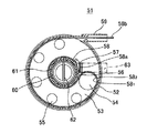
図4は、従来のフラットハーネス巻取装置の一形態を示すものである。 FIG. 4 shows an embodiment of a conventional flat harness winding device.
このフラットハーネス巻取装置51は、円形環状のケース52内に円板状のロータ53を有し、ロータ53に一つの大径な反転ロール54と、複数の小径なガイドロール55とを回転自在に軸支して設け、ケース52の中央の環状壁56にクランプ57で固定したフラットハーネス(フラットケーブル)58を環状壁56の周囲を経て反転ロール54に沿って折り返しつつ、各ガイドロール55に沿って湾曲させてケース52の案内通路59から外部に繰り出し自在に導出させ、ロータ55を中央のコイルばね60でハーネス巻取方向に付勢したものである。
The flat
コイルばね60の一端はロータ53の中央の中空軸61に、他端はケース52の中央のスリット62にそれぞれ固定されている。ケース52はロアケースとアッパケースで構成されている。フラットハーネス58の固定側部分58aはクランプ57を経て別の案内通路63から外部に導出されている。フラットハーネス58の固定側部分58aは固定体(図示せす)に配索され、可動側部分58bは可動体(図示せず)に配索される。フラットハーネス58は二枚を厚み方向に積層して使用している(フラットハーネス58の積層枚数は任意である)。
One end of the coil spring 60 is fixed to the
図1のフラットハーネス58の巻取状態からコイルばね60の付勢に抗してフラットハーネス58の可動側部分58bを引き出すことで、ロータ53が各ロール54,55と共に時計回りに回転しつつ反転ロール54が時計回りに自転し、環状壁56の外周のフラットハーネス部分が解かれて、反転ロール54が時計回りにクランプ57に近づく。
By pulling out the
しかしながら、上記従来のフラットハーネス巻取装置51にあっては、複数枚のフラットハーネス58を積層した状態で反転ロール54に沿って屈曲させているために、屈曲内側のフラットハーネス581と屈曲外側のフラットハーネス582との屈曲長さに差を生じ、この内外周差で内側のフラットハーネス581が弛んで座屈を生じやすくなり、座屈を生じた場合には、座屈部分が引っ掛かり等を生じて、フラットハーネス59の巻き取りや繰り出しがスムーズに行われず、座屈部分の傷みも生じ兼ねないという懸念があった。
However, the in the conventional flat
本発明は、上記した点に鑑み、複数枚のフラットハーネスを用いて多回路化に対応した際に、フラットハーネスの内外周差に起因する座屈を防止することのできるフラットハーネス巻取装置を提供することを目的とする。 In view of the above points, the present invention provides a flat harness winding device that can prevent buckling due to the difference between the inner and outer circumferences of a flat harness when a plurality of flat harnesses are used to support multi-circuiting. The purpose is to provide.
上記目的を達成するために、本発明の請求項1に係るフラットハーネス巻取装置は、ケース内に回転体が回動自在に配置され、該回転体の中心の孔部に該ケースの軸部が挿通され、該回転体に複数のハーネス分割ローラが回転自在に設けられ、該軸部に一端側を固定された複数のフラットハーネスが一枚ずつ独立して各ハーネス分割ローラに沿って屈曲配索されて、該ケースの開口から巻取可能に導出され、各フラットハーネスが各ハーネス分割ローラの外周面に接触した状態で該複数のフラットハーネスの引き出し及び巻き取りが行われ、前記各ハーネス分割ローラの径方向外側に近接して前記回転体に、外周面に沿って外側の他のフラットハーネスが摺接する湾曲状のハーネスガイドリブが設けられたことを特徴とする。
In order to achieve the above object, in the flat harness winding device according to
上記構成により、各フラットハーネスが中心の軸部から各ハーネス分割ローラを経てケースの開口に導かれ、フラットハーネスの引き出し時に、回転体が軸部を中心にハーネス引き出し方向に回転し、各フラットハーネスが軸部から巻きを解かれて各ハーネス分割ローラに沿って独立して繰り出され、フラットハーネスの巻き取り時に、回転体がフラットハーネスの復元力又はばね部材の付勢力又は手動操作等でハーネス巻き取り方向に回転し、各フラットハーネスが各ハーネス分割ローラに沿って独立して引き戻されつつ、軸部に巻き取られる。このように、フラットハーネスの引き出し時及び巻き取り時に各フラットハーネスが一枚ずつ独立して各ハーネス分割ローラの外周面に湾曲状に接触することで、フラットハーネスの内外周差(屈曲内側と屈曲外側とで生じるハーネス長さの違い)がなくなり、内外周差に起因するフラットハーネスの座屈が防止される。
また、上記構成により、一つのハーネス分割ローラに沿って配索されたフラットハーネスが隣のハーネス分割ローラの外側のハーネスガイドリブに摺接しつつ開口に導かれる。これにより、フラットハーネスが一つのハーネス分割ローラから隣のハーネス分割ローラに接触することが防止されて、隣のハーネス分割ローラにおけるフラットハーネスの内外周差の発生が防止される。
With the above configuration, each flat harness is guided to the opening of the case from the central shaft portion through each harness dividing roller, and when the flat harness is pulled out, the rotating body rotates in the harness pulling direction around the shaft portion. Is unwound from the shaft and is independently fed along each harness dividing roller, and when the flat harness is wound up, the rotating body is wound around the harness by the restoring force of the flat harness, the biasing force of the spring member, or manual operation. Rotating in the take-up direction, each flat harness is wound around the shaft portion while being independently pulled back along each harness dividing roller. In this way, when the flat harness is pulled out and wound up, each flat harness is independently brought into contact with the outer peripheral surface of each harness split roller in a curved shape, so that the difference between the inner and outer peripheries of the flat harness (bent inside and bent) The difference in harness length generated between the outside and the outside is eliminated, and buckling of the flat harness due to the difference between the inner and outer circumferences is prevented.
Moreover, the flat harness routed along one harness division | segmentation roller is guide | induced to opening by the said structure, slidingly contacting the harness guide rib outside the adjacent harness division | segmentation roller. Accordingly, the flat harness is prevented from coming into contact with the adjacent harness dividing roller from one harness dividing roller, and the occurrence of a difference between the inner and outer circumferences of the flat harness in the adjacent harness dividing roller is prevented.
請求項2に係るフラットハーネス巻取装置は、請求項1記載のフラットハーネス巻取装置において、前記各ハーネス分割ローラの間において前記回転体にハーネス支持ローラが回転自在に設けられたことを特徴とする。
The flat harness winding device according to
上記構成により、軸部からハーネス分割ローラに沿ったフラットハーネスがハーネス支持ローラを経て開口に導かれる。これにより、各ハーネス分割ローラ間のスペースにおいてフラットハーネスが弛まずに安定して支持され、また、フラットハーネスが一つのハーネス分割ローラから隣のハーネス分割ローラに接触して配索されることが防止されて、隣のハーネス分割ローラにおけるフラットハーネスの内外周差の発生が防止される(この場合、ハーネス支持ローラはハーネス分割ローラよりも回転体の径方向外側に配置される)。 With the above configuration, the flat harness along the harness dividing roller is guided from the shaft portion to the opening through the harness supporting roller. This prevents the flat harness from being loosely and stably supported in the space between each harness dividing roller, and prevents the flat harness from being routed from one harness dividing roller to the next harness dividing roller. Thus, occurrence of a difference between the inner and outer circumferences of the flat harness in the adjacent harness dividing roller is prevented (in this case, the harness support roller is disposed on the outer side in the radial direction of the rotating body than the harness dividing roller).
請求項3に係るフラットハーネス巻取装置は、請求項1又は2記載のフラットハーネス巻取装置において、前記複数のハーネス分割ローラが等間隔で配置されたことを特徴とする。
The flat harness winding device according to
上記構成により、中心の軸部から各ハーネス分割ローラに沿ってケースの開口に導かれた各フラットハーネスが、引き出し時に、等間隔(等角度)で配置された各ハーネス分割ローラに均一に引き出し方向の力を付与し、巻き取り時に、各ハーネス分割ローラで均一に巻き取り方向の力を付与されることで、回転体の回動がスムーズに行われると共に、フラットハーネスの引き出しや巻き取りが小さな力でスムーズに行われる。 With the above configuration, each flat harness led from the central shaft portion to the opening of the case along each harness split roller is uniformly pulled out to each harness split roller arranged at equal intervals (equal angles) when pulled out. When the winding force is applied, uniform force in the winding direction is applied to each harness dividing roller, so that the rotating body can be smoothly rotated and the flat harness can be pulled out and wound up little by little. Performed smoothly with force.
請求項4に係るフラットハーネス巻取装置は、請求項1〜3の何れかに記載のフラットハーネス巻取装置において、前記回転体が、前記孔部を有する基板部と、外周壁とを備え、該回転体をフラットハーネス巻取方向に付勢するばね部材が該外周壁の内側の空間に配置されたことを特徴とする。
The flat harness winding device according to claim 4 is the flat harness winding device according to any one of
上記構成により、ばね部材が回転体の内側の空間を有効利用して省スペースでコンパクトに収納され、ケースすなわちフラットハーネス巻取装置自体が高さ方向にコンパクト化される。 With the above configuration, the spring member is effectively stored in the space inside the rotating body and is compactly stored in a space-saving manner, and the case, that is, the flat harness winding device itself is compact in the height direction.
請求項1記載の発明によれば、複数枚のフラットハーネスを用いて多回路化に対応する際に、各ハーネス分割ローラに各フラットハーネスを独立して配索することで、ハーネス分割ローラにおけるフラットハーネスの内外周差の発生をなくすことができるから、内外周差に起因する座屈を防いで、フラットハーネスの引き出し操作性や巻き取り操作性を高めると共に、フラットハーネスの耐久性を高めることができ、しかも、座屈がないので軸部とハーネス分割ローラとの間のクリアランスを小さくして、ケースすなわちフラットハーネス巻取装置自体を径方向にコンパクト化することができる。
また、請求項1記載の発明によれば、一つのハーネス分割ローラに沿って配索されたフラットハーネスを隣のハーネス分割ローラに接触させることなくハーネスガイドリブに沿って弛みなく安定に導くことができると共に、隣のハーネス分割ローラとの接触に起因するフラットハーネスの内外周差の発生を防いで、上記の効果を促進させることができる。
According to the first aspect of the present invention, when a plurality of flat harnesses are used to support multiple circuits, each flat harness is routed independently to each harness dividing roller, so that the flat in the harness dividing roller Since it is possible to eliminate the occurrence of differences in the inner and outer circumferences of the harness, it is possible to prevent buckling due to the difference between the inner and outer circumferences, and to improve the flat harness's pulling out and winding operability and the flat harness's durability. In addition, since there is no buckling, the clearance between the shaft portion and the harness dividing roller can be reduced, and the case, that is, the flat harness winding device itself can be made compact in the radial direction.
In addition, according to the first aspect of the invention, the flat harness routed along one harness dividing roller can be stably guided along the harness guide rib without coming into contact with the adjacent harness dividing roller. At the same time, it is possible to prevent the difference between the inner and outer circumferences of the flat harness resulting from the contact with the adjacent harness dividing roller, and to promote the above effect.
請求項2記載の発明によれば、各ハーネス分割ローラの間でフラットハーネスをハーネス支持ローラで弛みなく安定に支持・案内させることができる。 According to the second aspect of the present invention, the flat harness can be stably supported and guided between the harness dividing rollers by the harness support roller without slack.
請求項3記載の発明によれば、等間隔(等角度)で配置されたハーネス分割ローラでフラットハーネスの引き出しや巻き取りを均一な力でスムーズ且つ確実に行わせることができる。 According to the third aspect of the present invention, it is possible to smoothly and surely pull out and wind up the flat harness with a uniform force by the harness dividing rollers arranged at equal intervals (equal angles).
請求項4記載の発明によれば、ばね部材を回転体の内側の空間に収容して、ケースすなわちフラットハーネス巻取装置自体を高さ方向にコンパクト化することができる。 According to invention of Claim 4 , a spring member can be accommodated in the space inside a rotary body, and a case, ie, a flat harness winding apparatus itself, can be made compact in a height direction.
図1〜図3は、本発明に係るフラットハーネス巻取装置の一実施形態を示すものである。 1 to 3 show an embodiment of a flat harness winding device according to the present invention.
図1(内部構造を示す平面図)の如く、このフラットハーネス巻取装置1は、合成樹脂製のケース2内に円形の回転体3を回動自在に設け、回転体3は、複数(本例で三つ)のハーネス分割ローラ4(41〜43)と、複数(本例で三つ)のハーネス支持ローラ5(51〜53)とを交互に有すると共に、図1,図2(要部拡大図)の如く、各ハーネス分割ローラ4の径方向外側に湾曲状のハーネスガイドリブ6(61〜63)を有し、ケース2のほぼ中央の軸部7に三枚のフラットハーネス8(81〜83)の各一端側を固定し、各フラットハーネス8を一枚ずつ独立して各分割ローラ4に沿って折り返し、各支持ローラ5と各ガイドリブ6とに沿って時計回りの方向に配索しつつ、複数枚のフラットハーネス8を厚み方向に重ねた(積層)した状態で、ケース2の開口9から導出させたものである。
As shown in FIG. 1 (plan view showing the internal structure), the flat
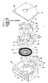
図3の如く、フラットハーネス巻取装置1は、扁平な前記ケース2と、ケース2の凹部10内に収容されるゼンマイばね(ばね部材)11及び前記回転体3と、回転体3の円形の基板部12に立設された各軸部13に回動自在に装着される前記各ローラ4,5と、ケース2の凹部10を覆うカバー14と、前記複数枚のフラットハーネス8(図1)とで構成される。
As shown in FIG. 3, the flat
ケース2は、外観視略矩形状で周壁15の一部に湾曲部15aを有し、周壁15の内側に円形の凹部10を有し、凹部10は、底壁16と下側の円形の内周面10aと上側の略円形の内周面10bとで囲まれて成り、上側の内周面10bは下側の内周面10aに段差面10cを介して続き、上側の内周面10bの接線方向の周壁15の一部にハーネス導出用の開口9が切欠形成され、底壁16の中央に断面円形(円柱状)の軸部7が一体に固定されて凹部10の上部開口10dとほぼ同じ高さに立設されている。軸部7は回転体3のローラ4,5よりも大径である。
The
ハーネス導出用の開口9の内側の一側面9aと内周面10bとは湾曲面17を介して連続している。軸部7の中央には、ゼンマイばね11の真直に折り曲げた内側端部11aを挿入固定させるスリット18が上端から下端まで垂直に設けられている。
The one
三枚のフラットハーネス8(図1)の内端側を固定させるには、例えば軸部7のスリット18を利用して、三枚のフラットハーネス8の内端側を重ねた状態で直交方向にL字状に折り曲げてスリット18内に挿入固定し、同時に上向きの折り曲げ部分(図示せず)をフラットハーネス8の固定側部分としてスリット18の上端からカバー14の円形の孔部19を通って外部に導出させることが好ましい。各フラットハーネス8の内端側を別々に軸部7の三等配の各スリット(図示しない固定部)に挿入固定させることも可能である。
In order to fix the inner end sides of the three flat harnesses 8 (FIG. 1), for example, using the
何れの場合も、各フラットハーネス8の固定側の端部は軸部7に沿って軸方向に外部に導出されて電源側等の回路に接続され、各フラットハーネス8の可動側の端部はケース2の開口9から導出されて負荷側等の回路に接続される。
In any case, the end portion on the fixed side of each
ケース2内の下側の内周面10aで囲まれた浅めの凹部空間10にゼンマイばね11が収容され、回転体3の水平な基板部12と、基板部12の外周に垂下された円形環状の外周壁20とで成る中空の回転体本体3’でゼンマイばね11を覆って、回転体本体3’の外周壁20の内側の空間29にゼンマイばね11を省スペースでコンパクトに収容し、回転体本体3’の外周壁20がケース2の下側の内周面10aに沿って回転自在に位置する。
A
ゼンマイばね11の折り返された外側端11bは回転体本体3’の外周壁20の内面側に引っ掛け等の手段で固定される。ケース2内の上側の内周面10bで囲まれた深めの凹部空間10に回転体3の各ローラ4,5やガイドリブ6が収容配置される。ケース2の開口9に隣接する外側の溝部21には例えばハーネス案内用の部材(図示せず)等が装着される。
The folded-back
ゼンマイばね11は、帯板状金属(ばね鋼)を螺旋状に巻いて形成され、真直に伸ばしても環状に復元する性質を有し、本例では自由状態で外側のばね部分11cが密に巻かれ、内側のばね部分11dが粗く巻かれている。ゼンマイばね11の板幅は細く形成され、ケース2内のフラットな凹部空間10に対応している。ゼンマイばね11は図1で回転体3をフラットハーネス8の巻取方向(反時計回り)に付勢する。
The
回転体3は、水平な基板部12の中央にケース2の軸部7を挿通(貫通)させる円形の孔部22を有し、図1の如く各ローラ4,5の間において複数(計三つ)の小径な孔部23を有し、孔部23から下側のゼンマイばね11の有無や巻き状態を目視確認可能である。中心の孔部22と外周壁20とのほぼ中間において基板部12の上面に等配(等ピッチ)ないし略等配に複数(本例で六本)の軸部13が立設されている。
The
軸部13は基板部12と一体に合成樹脂材で一体成形されることが好ましい。各軸部13の大きさ形状は同一である。各ローラ4,5は、好ましくは摺動性の良い合成樹脂で円筒形に形成され、軸部13を挿入する孔部4a,5aと、孔部4a,5aの内周面(符号4a,5aで代用)と同心な外周面4b,5bとを有する。各ローラ4,5の大きさ形状は同一である。
The
垂直な六本の軸部13のうちの一つおきの三本の軸部13の径方向外側に横断面円弧状(湾曲状)のガイドリブ6が近接して基板部12から垂直に立設されている。図1の如く、各ガイドリブ6は、中心の軸部7と外側の軸部13との各中心を結んだ仮想線(図示せず)から各ローラ4の外周に沿って反時計回りに略1/4周移動した位置までの範囲で円弧状に位置している。
図2の如く、各ガイドリブ6は円弧状の内周面6aと円弧状の外周面6bとを有した湾曲状の板部ないし壁部であり、回転体3の基板部12に一体樹脂成形されている。ガイドリブ6の内周面6aは分割ローラ4の外周面4bに沿って(近接して)位置し、分割ローラ4の外周面4bに沿ってフラットハーネス8が180°近い角度で折り返し反転される。フラットハーネス8の外周面とガイドリブ6の内周面6aとの間に若干の隙間24が形成されている。ガイドリブ6の外周面6bに沿って外側の他のフラットハーネス8がスムーズに摺接する。
As shown in FIG. 2, each
図3における薄肉のカバー14はケース2の一部を成すものであり、好ましくは金属板で形成され、中心の軸部7の上端面を露出させる円形の孔部19と、ケース2の周壁15の上面のねじ孔25にねじ止めするための小孔26と、位置決め用の鍔部27とを有している。
The
図1の各フラットハーネス8は、絶縁樹脂フィルムの間に導電線や導電箔といった導電部(図示せず)が複数列にサンドイッチ状に挟まれて配索され、厚み方向の良好な可撓性(屈曲性)を有する既存のものである。フラットハーネス8はフラットワイヤハーネスの略称であり、フラットケーブルとも呼称する。
Each
図1の如く、三つの分割ローラ4は120°の等間隔で配置されている。図1の状態でフラットハーネス8は回転体3の略1/4周の回転角度で巻き取られている。図1で下側の第一の分割ローラ41に中心の軸部7から接線方向に第一のフラットハーネス81が短く掛け渡され(掛け渡し部分を符号8aで示す)、180°近い角度で反転され(反転部分を符号8bで示す)、時計回り方向の隣接の第一の支持ローラ51に掛け渡されて(掛け渡し部分を符号8cで示す)、支持ローラ51の外周面で略くの字状に直接支持されて、導出用の開口9に向けて配索されている(配索部分を符号8dで示す)。配索部分8dは実際には開口9の内側の湾曲面17に沿って導出される(図1では便宜上開口9内の通路9bの中央に配索部分8dを図示している)。
As shown in FIG. 1, the three divided rollers 4 are arranged at equal intervals of 120 °. In the state of FIG. 1, the
図1で右上の第二の分割ローラ42に中心の軸部7から接線方向に第二のフラットハーネス82が短く掛け渡され(掛け渡し部分を符号8aで示す)、180°近い角度で反転され(反転部分を符号8bで示す)、時計回り方向の隣接の第二の支持ローラ52に掛け渡されて(掛け渡し部分を符号8cで示す)、支持ローラ52の外周面で略くの字状に直接支持され、支持ローラ52から時計回り方向の隣接の第一の分割ローラ41の外側の第一のガイドリブ61に掛け渡され(掛け渡し部分を符号8eで示す)、ガイドリブ61から第一の支持ローラ51に掛け渡されて(掛け渡し部分を符号8fで示す)、第一のフラットハーネス81の屈曲外側面に重なった状態で開口9に向けて配索されている(配索部分を符号8dで示す)。
In FIG. 1, the second
図1で左上の第三の分割ローラ43に中心の軸部7から接線方向に第三のフラットハーネス83が短く掛け渡され(掛け渡し部分を符号8aで示す)、180°近い角度で反転され(反転部分を符号8bで示す)、時計回り方向の隣接の第三の支持ローラ53に掛け渡されて(掛け渡し部分を符号8cで示す)、支持ローラ53の外周面で略くの字状に直接支持され、支持ローラ53から時計回り方向の隣接の第二の分割ローラ42の外側の第二のガイドリブ62に掛け渡され(掛け渡し部分を符号8gで示す)、ガイドリブ62から第二の支持ローラ52に掛け渡されて(掛け渡し部分を符号8hで示す)、第二のフラットハーネス82の屈曲外側面に重なった状態で、時計回り方向の隣接の第一の分割ローラ41の外側の第一のガイドリブ61に掛け渡され(掛け渡し部分を符号8eで示す)、第一の支持ローラ51に他の二枚のフラットハーネス81,82と共に掛け渡されて(掛け渡し部分を符号8fで示す)、開口9に向けて配索されている(配索部分を符号8dで示す)。
In FIG. 1, the third
図1の状態で第三の分割ローラ43の外側の第三のガイドリブ63にはフラットハーネス8が掛け渡されていないが、図1の状態からゼンマイばね11の力で回転体3が反時計回り(巻取方向)に回転した際に、第一の支持ローラ51から第三のガイドリブ63に各フラットハーネス8が重なった状態で掛け渡される。それと同時に、各フラットハーネス8が中心の軸部7の外周面に沿って反時計回りに巻き取られる。フラットハーネス8の引き出し長さの設定量に応じて、巻き取り時に各フラットハーネス8は重なった(積層された)状態でガイドリブ6の外周面に沿って一周ないしそれ以上の周回で巻き取られ、それと同時に、各フラットハーネス8が軸部7の外周に巻き取られる。「第一〜第三」は説明の便宜上のものである。
In the state of FIG. 1, the
ガイドリブ6は分割ローラ4の外周面に沿うハーネス部分(例えば8c)とガイドリブ6の外周面に沿うハーネス部分(例えば8f)とを区画して、両ハーネス部分(例えば8cと8f)の接触とそれに伴う摩擦を防止し、両ハーネス部分の巻き取りや引き出しを小さな摺動抵抗でスムーズに行わせる。各ガイドリブ6の時計回り方向の端部6c(図2)は、分割ローラ4から接線方向に引き出されるハーネス部分(例えば8c)に干渉しないように、ローラ4とハーネス部分(8c)との接点28(図2)よりも手前(反時計回りの方向)に位置している。
The
図1の状態からゼンマイばね11の付勢に抗してさらにフラットハーネス8を開口9から引き出すと、回転体3は時計回りに回転し、第一の支持ローラ51が回転体3と一体的に時計回りに移動(公転)して、第一の支持ローラ51からフラットハーネス8が径方向外側に離間し、第一の分割ローラ41が開口9に近づいた時点で、第一の分割ローラ41に沿うフラットハーネス81が他のフラットハーネス8と共に開口側に引っ張られ、それ以上の回転体3の回転が阻止される。図1はフラットハーネス8をほぼ完全に引き出す手前の状態である。
Further, when pulling out the
上記フラットハーネス巻取装置1によれば、回転体3に複数の分割ローラ4を設け、各分割ローラ4に各フラットハーネス8を分割・独立させて配索したことで、分割ローラ4において各フラットハーネス8の内外周差(屈曲外側のフラットハーネス8の先端部が屈曲内側のフラットハーネス8の先端部よりも後退する(短くなる)こと)が発生せず、内外周差に起因する屈曲内側のフラットハーネス8の座屈が防止され、それにより、フラットハーネス8の巻き取りや引き出しが引っ掛かり等なくスムーズに行われ、座屈に起因するフラットハーネス8の傷みも防止される。
According to the flat
分割ローラ4の数を二つ以上ないし三つ以上と増やすことで(図1の例では三つであるが)、座屈の心配なく接続側(負荷側等)の多回路化に対応することができる。また、分割ローラ4におけるフラットハーネス8の座屈が防止され、中心の軸部7へのフラットハーネス8の巻き取り時に座屈を生じないから、軸部7と分割ローラ4との間のクリアランスを小さく設定することができ(座屈があるとクリアランスを大きくしないと座屈部が通過できない)、ケース2すなわちフラットハーネス巻取装置1全体のサイズを径方向にコンパクト化することができる。
By increasing the number of divided rollers 4 to two or more (three in the example of FIG. 1), it is possible to cope with multiple circuits on the connection side (load side, etc.) without worrying about buckling. Can do. Further, since the buckling of the
なお、フラットハーネス8に替えて例えば光ファイバをフラット状に配索した他のフラット配索材を用いることも可能である。この場合は軸部7側でのフラット配索材の折り曲げは不可である。フラットハーネス8をフラット配索材と呼称してもよい。本発明は、フラットハーネス巻取装置1として以外にフラット配索材巻取機構や巻取構造等としても有効なものである。
Instead of the
また、上記実施形態において、フラットハーネス8を四枚とした場合は、分割ローラ4を回転体3に四つ等配に配置し、各分割ローラ4の間に支持ローラ5を四つ配置する。各支持ローラ5は等配に配置されることが好ましいが、隣接する分割ローラ4と支持ローラ5との間隔は適宜設定可能である。フラットハーネス8を二枚とした場合は、分割ローラ4を二つ等配に配置し、分割ローラ4の間に計二つないしそれ以上の支持ローラ5を配置してもよいが、図1の三つの分割ローラ4のうちの二つを使用する(残りの一つは未使用とする)ことも可能である。
Moreover, in the said embodiment, when the
フラットハーネス8の数が多く、例えば六枚である場合は、図1の三つの各分割ローラ4に二枚ずつ積層してフラットハーネス8を配索することも可能である。この場合、分割ローラ4における内外周差の発生は否めないが、より多回路化するためには有効である(六枚のフラットハーネス8を積層して用いるよりは内外周差は小さくなる)。分割ローラ4とは複数のフラットハーネス8を一枚ずつ分割して(分離・独立させて)配索させるローラの意味である。
When the number of the
また、図1において各支持ローラ5を省略(排除)し、分割ローラ5から導出されたフラットハーネス部分8を隣接の分割ローラ4の外側のガイドリブ6で支持させることも可能である。特にフラットハーネス6の数すなわち分割ローラ4の数が多い場合は(フラットハーネス8の数と分割ローラ4の数は等しい)、支持ローラ5を省略して分割ローラ4の配置スペースを確保することができる。
Further, it is also possible to omit (exclude) each
また、図1において各ガイドリブ6を省略し、各分割ローラ4を中心の軸部7に接近させて配置し、各支持ローラ5を軸部7から離間させて回転体3の外周寄りに配置して、例えば第二の分割ローラ42から導出されたフラットハーネス部分82を第二の支持ローラ52で支持しつつ第一の分割ローラ41を非接触で通過させ、第一の支持ローラ51で支持させることも可能である。これは分割ローラ4の数が多い場合(各分割ローラ4が接近している場合)に特に有効である。
In FIG. 1, the
また、ばね部材としてゼンマイばね11に代えてフラットな形状のコイルばね等を用いることも可能である。また、ばね部材を省略して各フラットハーネス8の剛性による復元力を利用して各フラットハーネス8を巻き戻させることも可能である(引き出し長さの短い場合に限る)。
Further, a flat coil spring or the like can be used as the spring member in place of the
本発明に係るフラットハーネス巻取装置は、複数枚のフラットワイヤハーネスを積層して自動車等の接続側の補機等の多回路化に対応し、しかもフラットハーネスの巻取時や引出時の座屈の発生を防止して、巻取操作性や引出操作性を高めると共に、補機等への常時給電の信頼性を高めるために利用することができる。 The flat harness winding device according to the present invention is adapted for multi-circuiting of auxiliary machines on the connection side of an automobile or the like by stacking a plurality of flat wire harnesses, and also when the flat harness is wound or pulled out. It can be used to prevent the occurrence of bending and to improve the winding operability and the pulling out operability, and to improve the reliability of the constant power supply to the auxiliary machinery and the like.
1 フラットハーネス巻取装置
2 ケース
3 回転体
4 ハーネス分割ローラ
5 ハーネス支持ローラ
6 ハーネスガイドリブ
7 軸部
8 フラットハーネス
9 開口
11 ゼンマイばね(ばね部材)
12 基板部
20 外周壁
22 孔部
DESCRIPTION OF
12
Claims (4)
Priority Applications (5)
| Application Number | Priority Date | Filing Date | Title |
|---|---|---|---|
| JP2010260890A JP6066543B2 (en) | 2010-11-24 | 2010-11-24 | Flat harness winding device |
| US13/988,847 US9227813B2 (en) | 2010-11-24 | 2011-11-21 | Flat harness winding device |
| CN201180056590.4A CN103229377B (en) | 2010-11-24 | 2011-11-21 | Flat wire harness coiler device |
| PCT/JP2011/077288 WO2012070673A1 (en) | 2010-11-24 | 2011-11-21 | Flat harness winding device |
| EP11843753.2A EP2643912B1 (en) | 2010-11-24 | 2011-11-21 | Flat harness winding device |
Applications Claiming Priority (1)
| Application Number | Priority Date | Filing Date | Title |
|---|---|---|---|
| JP2010260890A JP6066543B2 (en) | 2010-11-24 | 2010-11-24 | Flat harness winding device |
Publications (2)
| Publication Number | Publication Date |
|---|---|
| JP2012115008A JP2012115008A (en) | 2012-06-14 |
| JP6066543B2 true JP6066543B2 (en) | 2017-01-25 |
Family
ID=46146008
Family Applications (1)
| Application Number | Title | Priority Date | Filing Date |
|---|---|---|---|
| JP2010260890A Expired - Fee Related JP6066543B2 (en) | 2010-11-24 | 2010-11-24 | Flat harness winding device |
Country Status (5)
| Country | Link |
|---|---|
| US (1) | US9227813B2 (en) |
| EP (1) | EP2643912B1 (en) |
| JP (1) | JP6066543B2 (en) |
| CN (1) | CN103229377B (en) |
| WO (1) | WO2012070673A1 (en) |
Families Citing this family (10)
| Publication number | Priority date | Publication date | Assignee | Title |
|---|---|---|---|---|
| JP5896409B2 (en) * | 2012-02-16 | 2016-03-30 | 矢崎総業株式会社 | Flat cable winding device |
| JP6029138B2 (en) * | 2013-01-22 | 2016-11-24 | 矢崎総業株式会社 | Power supply device |
| JP6025205B2 (en) | 2013-03-14 | 2016-11-16 | 矢崎総業株式会社 | Flat cable winding device |
| JP6276225B2 (en) * | 2015-08-04 | 2018-02-07 | 矢崎総業株式会社 | Wire harness winding device |
| JP2019218150A (en) * | 2018-06-15 | 2019-12-26 | 矢崎総業株式会社 | Flat cable winding device |
| US10973321B2 (en) | 2018-09-04 | 2021-04-13 | Steelcase Inc. | Workspace system and components and method for the use thereof |
| JP2020054097A (en) * | 2018-09-26 | 2020-04-02 | 矢崎総業株式会社 | Flat cable winding device and flat cable routing structure |
| CN110247362B (en) * | 2019-05-10 | 2020-11-06 | 湖北海洋工程装备研究院有限公司 | Cable protection device and rotating device |
| JP7259602B2 (en) * | 2019-07-08 | 2023-04-18 | 株式会社オートネットワーク技術研究所 | Wire harness routing device |
| CN117049277B (en) * | 2023-10-10 | 2023-12-12 | 派纳维森(苏州)电气科技有限公司 | Intelligent winding and collecting device for flat wire harness |
Family Cites Families (14)
| Publication number | Priority date | Publication date | Assignee | Title |
|---|---|---|---|---|
| US6213797B1 (en) * | 1994-07-19 | 2001-04-10 | Methode Electronics, Inc. | Clockspring having non-compliant and compliant roller members |
| US5882216A (en) | 1996-07-15 | 1999-03-16 | Alps Electric Co., Ltd. | Rotary connector |
| JP3595130B2 (en) * | 1997-10-17 | 2004-12-02 | 矢崎総業株式会社 | Flat cable winding device |
| CN2563136Y (en) | 2001-12-07 | 2003-07-30 | 廖生兴 | Short line distance thread winding box |
| JP4316214B2 (en) * | 2002-09-09 | 2009-08-19 | 古河電気工業株式会社 | Rotating connector |
| JP2004266941A (en) * | 2003-02-28 | 2004-09-24 | Sumitomo Wiring Syst Ltd | Cable reel |
| JP4205516B2 (en) * | 2003-04-11 | 2009-01-07 | 古河電気工業株式会社 | Flat cable winding and unwinding device |
| TWM263680U (en) * | 2004-07-13 | 2005-05-01 | Sheng-Shing Liau | Reel structure commonly for two cables |
| DE102005002676B3 (en) | 2005-01-20 | 2006-06-14 | Tyco Electronics Amp Gmbh | Spring mounting for steering columns comprises outer ring fixed to vehicle bodywork and inner ring which can rotate, flexible roller being mounted between rings and flat cable fitted into groove inside outer ring passing around it |
| JP4152414B2 (en) * | 2006-02-09 | 2008-09-17 | 矢崎総業株式会社 | Rotating connector device |
| JP2008021555A (en) | 2006-07-13 | 2008-01-31 | Alps Electric Co Ltd | Rotating connector |
| CN201097436Y (en) * | 2007-08-03 | 2008-08-06 | 颜旭利 | Hub |
| JP4448882B2 (en) * | 2008-01-08 | 2010-04-14 | アルプス電気株式会社 | Rotating connector |
| JP2010074872A (en) | 2008-09-16 | 2010-04-02 | Yazaki Corp | Feeder system |
-
2010
- 2010-11-24 JP JP2010260890A patent/JP6066543B2/en not_active Expired - Fee Related
-
2011
- 2011-11-21 US US13/988,847 patent/US9227813B2/en not_active Expired - Fee Related
- 2011-11-21 WO PCT/JP2011/077288 patent/WO2012070673A1/en active Application Filing
- 2011-11-21 CN CN201180056590.4A patent/CN103229377B/en not_active Expired - Fee Related
- 2011-11-21 EP EP11843753.2A patent/EP2643912B1/en not_active Not-in-force
Also Published As
| Publication number | Publication date |
|---|---|
| EP2643912B1 (en) | 2016-10-19 |
| CN103229377B (en) | 2016-06-29 |
| EP2643912A4 (en) | 2014-06-04 |
| US20130248632A1 (en) | 2013-09-26 |
| EP2643912A1 (en) | 2013-10-02 |
| CN103229377A (en) | 2013-07-31 |
| WO2012070673A1 (en) | 2012-05-31 |
| JP2012115008A (en) | 2012-06-14 |
| US9227813B2 (en) | 2016-01-05 |
Similar Documents
| Publication | Publication Date | Title |
|---|---|---|
| JP6066543B2 (en) | Flat harness winding device | |
| JP5856492B2 (en) | Flat cable winding device and flat cable routing structure | |
| JP6025205B2 (en) | Flat cable winding device | |
| US9653902B2 (en) | Flat cable winding device and assembling method thereof | |
| JP5117528B2 (en) | Rotating connector device | |
| JP5896409B2 (en) | Flat cable winding device | |
| JP2019218150A (en) | Flat cable winding device | |
| JP5065508B2 (en) | Rotating connector device | |
| JP2010172116A (en) | Harness winding type power supply device | |
| JP5117595B2 (en) | Rotating connector device | |
| JP5837335B2 (en) | Flat cable routing structure | |
| JP2014103712A (en) | Motor | |
| JP2011228287A5 (en) | ||
| JP5053433B2 (en) | Rotating connector device | |
| JP2007267492A (en) | Insulator for motor, armature core equipped with insulator for motor, and motor | |
| KR20130087998A (en) | Rotational connector device | |
| JP5624972B2 (en) | Rotating connector device | |
| JP2013020850A (en) | Rotary connector device | |
| JP2013151335A (en) | Flat cable winding device and flat cable wiring structure | |
| US20170275133A1 (en) | Flat cable reel device | |
| JP6285712B2 (en) | Flat cable winding device | |
| JP2008060089A (en) | Power supply method to mobile unit, and power supply device to mobile unit | |
| JP2009071995A5 (en) | ||
| JP4101001B2 (en) | Flat cable winding number design method for power feeding device to moving body and power feeding device to moving body | |
| JP2013188053A (en) | Flat cable winding apparatus |
Legal Events
| Date | Code | Title | Description |
|---|---|---|---|
| A621 | Written request for application examination |
Free format text: JAPANESE INTERMEDIATE CODE: A621 Effective date: 20131017 |
|
| A521 | Request for written amendment filed |
Free format text: JAPANESE INTERMEDIATE CODE: A523 Effective date: 20131106 |
|
| A131 | Notification of reasons for refusal |
Free format text: JAPANESE INTERMEDIATE CODE: A131 Effective date: 20150609 |
|
| A521 | Request for written amendment filed |
Free format text: JAPANESE INTERMEDIATE CODE: A523 Effective date: 20150708 |
|
| A02 | Decision of refusal |
Free format text: JAPANESE INTERMEDIATE CODE: A02 Effective date: 20160209 |
|
| A521 | Request for written amendment filed |
Free format text: JAPANESE INTERMEDIATE CODE: A523 Effective date: 20160303 |
|
| RD04 | Notification of resignation of power of attorney |
Free format text: JAPANESE INTERMEDIATE CODE: A7424 Effective date: 20160323 |
|
| A911 | Transfer to examiner for re-examination before appeal (zenchi) |
Free format text: JAPANESE INTERMEDIATE CODE: A911 Effective date: 20160420 |
|
| A912 | Re-examination (zenchi) completed and case transferred to appeal board |
Free format text: JAPANESE INTERMEDIATE CODE: A912 Effective date: 20160701 |
|
| A521 | Request for written amendment filed |
Free format text: JAPANESE INTERMEDIATE CODE: A523 Effective date: 20161019 |
|
| A61 | First payment of annual fees (during grant procedure) |
Free format text: JAPANESE INTERMEDIATE CODE: A61 Effective date: 20161220 |
|
| R150 | Certificate of patent or registration of utility model |
Ref document number: 6066543 Country of ref document: JP Free format text: JAPANESE INTERMEDIATE CODE: R150 |
|
| R250 | Receipt of annual fees |
Free format text: JAPANESE INTERMEDIATE CODE: R250 |
|
| R250 | Receipt of annual fees |
Free format text: JAPANESE INTERMEDIATE CODE: R250 |
|
| R250 | Receipt of annual fees |
Free format text: JAPANESE INTERMEDIATE CODE: R250 |
|
| LAPS | Cancellation because of no payment of annual fees |