【0001】
【発明の属する技術分野】
本発明は、自動車のステアリング装置に装備するケーブルリールに関し、詳しくは、簡易な構造により低コスト化を実現すると共に、フラットケーブルの摩擦による損傷を防止するものである。
【0002】
【従来の技術】
近時、ステアリングコラム側に固定される固定体と、ステアリングシャフト側に固定される可動体とで環状中空部からなるフラットケーブル収容室を設け、該フラットケーブル収容室内にフラットケーブルを回転自在に収容したケーブルリールにおいて、上記フラットケーブルを反転させて収容すると共に、該フラットケーブルの回転ガイド部材として環状中空部に複数のローラを回転自在に設けたものが提供されている。
【0003】
例えば、図11に示すケーブルリール1では、外枠2aと底板2bとで構成され外筒となる固定体2と内筒となる可動体3とが相対的に回転可能に連結され、固定体2と可動体3との間に形成される環状の環状中空部4内に、ローラ5を周方向に間隔をあけて取り付けたC形状のリング部材6を収容している。これらローラ5と可動体3からなる内筒部3aの間に形成される内周通路7と、ローラ5と固定体2の外枠2aとの間に形成される外周通路8とに、フラットケーブル9をU字状に反転させて巻回している。フラットケーブル9の一端は固定体2に、他端を可動体3に固定している。
【0004】
上記ケーブルリール1では、可動体3が一方向に回転されると、フラットケーブル9が反転部となるローラ5間を通ってU形状に反転しながら内周通路7に巻き込まれる一方、可動体3を反対方向に回転させるとフラットケーブル9は巻き戻され、外周通路8側に送り出される。
【0005】
【特許文献1】
特開2003−12234号公報
【0006】
【発明が解決しようとする課題】
しかしながら上記構成とすると、C形状のリング部材6と該リング部材6に取り付ける複数のローラ5を用いているため、部品点数が多くコスト高になるという問題がある。また、組立工数が多く繁雑であり、組立作業性が良くないという問題もある。さらに、ローラ5が重い場合、摩擦によりフラットケーブル9への負荷が増えるため、フラットケーブルがスムーズに回転しずらくなる問題もある。
【0007】
本発明は上記問題に鑑みてなされたものであり、ケーブルリール内の構造を簡易な構造として、コストの低減および組立作業性の向上を図ると共に、摩擦によるフラットケーブルの損傷及び切断を防止することを課題としている。
【0008】
【課題を解決するための手段】
上記課題を解決するために、本発明は、筒状の固定体と可動体とを組み合わせて、フラットケーブル収容室となる環状中空部を囲む外筒部、内筒部、底板部および天板部とを構成し、上記環状中空部に円弧形状のケーブルガイド部材を配置し、一端を上記可動体に固定すると共に他端を上記固定体に固定したフラットケーブルを、上記内筒部と上記ケーブルガイド部材との間の内周通路と、上記外筒部と上記ケーブルガイド部材との間の外周通路とに巻き方向を反転して巻き付けているケーブルリールにおいて、
上記ケーブルガイド部材は樹脂成形品からなり、上記環状中空部の水平断面に沿った円弧形状で、かつ、内周面と外周面の長さ方向の両端に円弧状連結部を備え、該円弧状連結部のうち上記フラットケーブルを巻き付けて反転させる円弧状連結部には、先端面より切り込んだローラ組付用の凹部を設け、該凹部に樹脂製のローラを回転自在に取り付けると共に、該ローラの外周面の一部を凹部の先端開口より突出させ、該ローラの突出面に上記フラットケーブルを巻き付けて反転させる構成としていることを特徴とするケーブルリールを提供している。
【0009】
上記構成とすると、ケーブルリールの環状中空部内に収容するガイド部材を樹脂成形品としているため、非常に軽量化できることよりフラットケーブルの巻き締め、巻き戻しに容易に追従して移動させることができる。また、ガイド部材の両端は円弧形状となっているので、フラットケーブルを反転させて案内する際、フラットケーブルはその円弧面に沿って摺動するので、フラットケーブルとの接触面を傷つけることがない。更に、フラットケーブルを反転させる円弧状連結部には、樹脂製のローラを回転自在に突出させて、その突出面にフラットケーブルを巻き付けて反転させるようにしているので、フラットケーブルとの間に生じる摩擦抵抗を極力小さくすることができる。これにより、フラットケーブルの回転時にかかる負荷が低減され、フラットケーブルをスムーズに回転でき、摩擦によるフラットケーブルの損傷を防止できる。
【0010】
上記ケーブルガイド部材は、上記環状中空部内を分割した各円弧形状に成形された複数のガイド部材からなり、隣接するガイド部材の隙間を反転空間とし、該反転空間に面する上記円弧状連結部に上記ローラを取り付けるようにしてもよい。このようにすれば、フラットケーブルを複数組使用する場合においても複数のガイド部材の隣接する反転空間を利用してフラットケーブルを別経路で反転して案内させることができる。
【0011】
上記ローラは円筒形状あるいは球状とし、上記ケーブルガイド部材に設ける上記ローラ組付用の凹部は上記ローラ形状を回転自在に内嵌させる形状とし、かつ、上記凹部に軸部あるいは軸受部のいずれか一方を設けていると共に、上記ローラに軸受部あるいは軸部のいずれか他方を設け、該軸部を軸受部に回転自在に組み付けるようにしている。このように構成すれば、ケーブルガイド部材のローラ組付用の凹部に対し、軸部あるいは軸受部を介してローラを内嵌するのみで簡易に組み付けることができ、組立作業性を向上することができる。なお、ローラが球形状の場合は、軸孔と軸部に代えて球状のローラに対応する曲面形状の凹部によりローラを回動自在に支持するようにしてもよい。
【0012】
更に、上記ケーブルガイド部材は中空体からなるブロー成形品あるいは、内周枠、外周枠および両端の円弧状連結枠を有すると共に上下両面は開口された枠体からなる射出成形品あるいは樹脂製の帯状体を屈曲させて熱硬化処理を施した樹脂製品から構成している。
上記構成とすると、ケーブルリールの環状中空部内に収容するガイド部材が中空形状となるので、ガイド部材自体を非常に軽量化することができ、これによりフラットケーブルの巻き締め、巻き戻しに対し、迅速に追従して移動するので、フラットケーブルとガイド部材との間に生じる摩擦をより一層小さくすることができる。
【0013】
【発明の実施の形態】
以下、本発明の実施の形態を図面を参照して説明する。
図1乃至図6は第1実施形態を示す。
【0014】
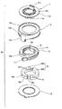
ケーブルリール10は、外枠12と底板15とで外筒を構成している固定体20と、内筒となる可動体11とが相対的に回転可能に連結している。
可動体11は、内筒部11dと、内筒部11dの上端よりつば状に突出した環状の第1天板部11aと、第1天板部11aの内筒部11d側に設けた環状凹部11bと、内筒部11dの上端より上方に突設したコネクタ収容部11cを備えている。固定体20の外枠12は、外筒となる外筒部12bと、外筒部12bの上端付近より内方に突出した環状の第2天板部12aと、外筒部12bの外面より下方に突設したコネクタ収容部12cとを備えている。底板15は、ケーブルリール10の底板部となる環状板であり、外枠12とロック固定している。
【0015】
可動体11の内筒部11dの外周面と固定体20の外筒部12bの内周面との間に形成される環状中空部24には、ケーブルガイド部材18を回転自在に収容している。該ケーブルガイド部材18は周方向に2つに分割されたガイド部材18A、18Bからなる。環状中空部24の内部にはフラットケーブル13、14を収容し、上記ガイド部材18A、18Bに反転式に巻き付けている。
【0016】
詳しくは、フラットケーブル13、14の一端のコネクタ16を可動体11のコネクタ収容部11cに嵌合させ、ガイド部材18A、18Bの内周側18cと可動体11の内筒部11dの外周面との間の内周通路Iに巻き付けている。フラットケーブル13、14の中間部分を反転部13a、14aとして2つのガイド部材18A、18B間である反転空間21A、21Bを通してU形状に巻き方向を反転させ、ガイド部材18A、18Bの外周側18bと外筒部12bの内周面との間の外周通路IIにて逆方向に巻回し、他端のコネクタ17を外枠12のコネクタ収容部12cに収容している。
【0017】
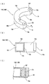
図3に示すように、ケーブルガイド部材18を構成する2個のガイド部材18A、18Bは、ブロー成形された薄肉の樹脂成形品からなる中空部材で、その全体形状を環状中空部24の水平断面に沿った略半円弧形状としている。ガイド部材18A、18Bは、内外周壁18b、18cおよび上下壁18d、18eにより中空部を囲む断面四角枠形状の閉断面とし、長さ方向の両端部には円弧状連結部18aを設けている。
【0018】
円弧状連結部18aの先端部には、フラットケーブル13、14の反転部を案内する円筒形状のローラ19を回転自在に取り付けている。ガイド部材18A、18Bには、ローラ19を組付けるために円弧状連結部18aの先端面より切り込んだローラ組付用の凹部18fを設け、この凹部18fの底壁18gから立設した支軸18hに対しローラ19の軸心に沿って形成した軸孔19aを嵌合することで、ローラ19を回転自在に取り付けるようにしている。ローラ19は、凹部18fに取り付けた状態で円弧状連結部18aの先端開口より外周面の一部が僅かに突出する状態で取り付け、このローラ19の突出面にフラットケーブル13、14を巻き付けて反転させることで、フラットケーブル13、14の移動に追従してローラ19を回転させるようにしている。
【0019】
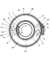
次に、ケーブルリール10の動作について説明する。
ステアリングシャフト(図示せず)の回転操作により、図4に示すように、可動体11が一方向(時計回転方向)に回転されるとフラットケーブル13、14が巻き締められ、上記外周通路IIのフラットケーブル13、14が、反転空間21A、21Bを折り返し状に通過して、上記内周通路Iに巻き付けられる。
このフラットケーブル13、14の巻き締めに作用に応じて、ガイド部材18A、18Bは環状中空部24内に回転自在に収容されているため、ケーブルリール10の中心を支点として、フラットケーブル13、14との摩擦で、それぞれ時計回転方向に移動する。上記のように、フラットケーブル13、14がガイド部材18A、18Bの円弧状連結部18aの端面に沿って反転して巻き締められるとき、円弧状連結部18aの端部に突出させたローラ19が追従して回転することで、ガイド部材18A、18Bとの間の摩擦抵抗が軽減され、円滑なる巻き締め動作が行われる。
【0020】
一方、図5に示すように、可動体11が逆方向(反時計方向)に回転されるとフラットケーブル13、14は巻き戻され、内周通路Iのフラットケーブル13、14が反転空間21A、21Bを折り返し状に通過して上記外周通路IIに送り出される。このフラットケーブル13、14の巻き戻しにより、ガイド部材18A、18Bは反時計方向に移動する。フラットケーブル13、14の巻き戻し時にも巻き締め時と同様に、フラットケーブル13、14の移動にローラ19が回転して追従することで、ガイド部材18A、18Bとフラットケーブル13、14との間の摩擦抵抗を軽減することができる。
【0021】
上記構成のケーブルリール10においては、環状中空部24内に収容する2つガイド部材18A、18Bはブロー成形品とし、中空且つ外殻を薄肉として軽量化しているため、フラットケーブル13、14の巻き締め、巻き戻しに容易に追従して移動し、フラットケーブル13、14の回転時に負荷を与えず、スムーズに回転させることができる。
かつ、ガイド部材18A、18Bはブロー成形品であるため、簡単且つ安価に製造できると共に、これらガイド部材を環状中空部に挿入するだけで良いため、組み立ても簡単となる。よって、従来の複数のローラをC型リングに組みつけている場合と比較して部品点数および組立工数を削減でき、製造コストを低下させることができる。
【0022】
図6は第2実施形態を示す。
フラットケーブル13を1系統のみ使用する場合に、ガイド部材38としてC形状の1個のみとしたのもので、対向する端部間を反転空間31として、フラットケーブル13を一方に取り付けたローラ39に対し反転して案内させるようにしている。
なお、その他の構成は、第1実施形態と同様のため、同一符号を付して説明を省略する。
【0023】
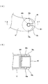
図7は第3実施形態を示す。
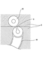
ローラ49を回転自在に取り付けるため、ローラ49の上下面に支軸49aを突設する一方、ローラ49を受け入れる凹部48fの上下壁部38gには、中央に支軸49aに対応する軸孔48hを形成すると共に、軸孔48hに連通すると共に僅かに幅狭のスリット48iを形成している。このスリット48iに対し、ローラ49の支軸49aを無理入れすることで、支軸49aを軸孔48h内に回転自在に支持させるようにしている。
なお、その他の構成は、第1実施形態と同様のため、同一符号を付して説明を省略する。
【0024】
図8(A)はローラ19の変形例であり、円筒状の形状に代えて球状のローラ59を使用したものである。このようにすると、反転部におけるフラットケーブルとの接触が点接触状態となって、ローラ59の回転作用と共に反転時の摩擦抵抗を更に軽減することができる。更に、図8(B)は変形例を示し、ローラ59’を回動自在に取り付けるガイド部材18側の凹部18f’を、球面を受け入れて内嵌可能な球面の窪み形状とし、軸部なしでローラ59’を支持するようにしている。
【0025】
図9は第4実施形態を示す。
ローラ69とケーブルガイド部材68とを金型D内での成形時に切断用連結帯Bを介して一体成形し、切断用連結帯Bを切断することで、両者を型内または取り出し後に組付け可能としている。
【0026】
なお、第1実施形態において、ケーブルガイド部材18は中空体からなるブロー成形品としているが、図10に示すように、内周78c、外周78cおよび両端の円弧状連結部78aを有すると共に上下両面は開口された枠体からなる射出成形品あるいは樹脂製の帯状体を屈曲させて熱硬化処理を施した樹脂製品としてもよい。また、複数のガイド部材の個数は2個に限定されず、収容するフラットケーブの本数に応じて、3個以上とすることもできる。
【0027】
【発明の効果】
以上の説明より明らかなように本発明によれば、ガイド部材の端面部に回転自在に取り付けたローラにより、フラットケーブルの巻き締め、巻き戻し時に反転部をローラによって回転自在に保持することができるので、フラットケーブルの円滑なる巻き締め、巻き戻しを行うことができる。また、ガイド部材は軽量構造を採用しているので、ローラによる案内と共に、ガイド部材自体の移動が円滑となってフラットケーブルに追従して移動するので、フラットケーブルと各ガイド部材との間に生じる摩擦を一層小さくすることができる。
【図面の簡単な説明】
【図1】本発明の第1実施形態のケーブルリールの分解斜視図である。
【図2】(A)(B)は第1実施形態のケーブルリールの断面図である。
【図3】(A)は第1実施形態のケーブルガイド部材の斜視図、(B)は平面図、(C)はX−X線断面図である。
【図4】フラットケーブルを巻き締めた状態を示すケーブルリールの断面図である。
【図5】フラットケーブルを巻き戻した状態を示すケーブルリールの断面図である。
【図6】第2実施形態のケーブルリールの断面図である。
【図7】(A)は第3実施形態のケーブルリールにおけるガイド部材の要部を示す平面図、(B)はY−Y断面図である。
【図8】(A)(B)はケーブルリールにおけるローラの支持構造の変形例を示す図である。
【図9】第4実施形態のケーブルリールにおけるガイド部材の成形状態を示す要部の断面図である。
【図10】ケーブルリールにおけるガイド部材の変形例を示す要部の斜視図である。
【図11】従来例を示す断面図である。
【符号の説明】
10 ケーブルリール
11 可動体
11a 第1天板部
11b 環状凹部
11d 内筒部
12a 第2天板部
12b 外筒部
13、14 フラットケーブル
15 底板
18 ケーブルガイド部材
18A、18B、38、68、78 ガイド部材
18a、78a 円弧状連結部
18f、48f 凹部
19、39、49、59、59’、69 ローラ
20 固定体
21A、21B、31 反転空間
24 環状中空部
B 切断用連結帯[0001]
TECHNICAL FIELD OF THE INVENTION
The present invention relates to a cable reel mounted on a steering device of an automobile, and more particularly, to a simple structure that realizes a reduction in cost and prevents a flat cable from being damaged by friction.
[0002]
[Prior art]
In recent years, a flat cable housing chamber having an annular hollow portion is provided by a fixed body fixed to the steering column side and a movable body fixed to the steering shaft side, and the flat cable is rotatably housed in the flat cable housing chamber. In such a cable reel, there is provided a cable reel in which the flat cable is inverted and accommodated, and a plurality of rollers are rotatably provided in an annular hollow portion as a rotation guide member of the flat cable.
[0003]
For example, in a cable reel 1 shown in FIG. 11, a fixed body 2 which is an outer cylinder and is composed of an outer frame 2a and a bottom plate 2b and a movable body 3 which is an inner cylinder are relatively rotatably connected. A C-shaped ring member 6 in which rollers 5 are attached at intervals in the circumferential direction is accommodated in an annular hollow portion 4 formed between the movable member 3 and the movable member 3. A flat cable is provided between an inner peripheral passage 7 formed between the roller 5 and the inner cylindrical portion 3a formed of the movable body 3 and an outer peripheral passage 8 formed between the roller 5 and the outer frame 2a of the fixed body 2. 9 is turned in a U-shape and wound. One end of the flat cable 9 is fixed to the fixed body 2 and the other end is fixed to the movable body 3.
[0004]
In the cable reel 1, when the movable body 3 is rotated in one direction, the flat cable 9 is wound around the inner peripheral passage 7 while being inverted into a U-shape while passing between the rollers 5 serving as a reversing part. When the is rotated in the opposite direction, the flat cable 9 is rewound and sent out to the outer peripheral passage 8 side.
[0005]
[Patent Document 1]
JP 2003-12234 A
[Problems to be solved by the invention]
However, in the above configuration, since the C-shaped ring member 6 and the plurality of rollers 5 attached to the ring member 6 are used, there is a problem that the number of parts is large and the cost is high. There is also a problem that the number of assembling steps is large and complicated, and the assembling workability is not good. Further, when the roller 5 is heavy, the load on the flat cable 9 increases due to friction, so that there is a problem that the flat cable is difficult to rotate smoothly.
[0007]
SUMMARY OF THE INVENTION The present invention has been made in view of the above problems, and has a simple structure in a cable reel to reduce costs and improve assembling workability, and to prevent damage and cutting of a flat cable due to friction. Is an issue.
[0008]
[Means for Solving the Problems]
In order to solve the above problems, the present invention provides a combination of a tubular fixed body and a movable body, and an outer tubular portion, an inner tubular portion, a bottom plate portion, and a top plate portion surrounding an annular hollow portion serving as a flat cable housing chamber. An arc-shaped cable guide member is disposed in the annular hollow portion, and a flat cable having one end fixed to the movable body and the other end fixed to the fixed body is provided by the inner cylindrical portion and the cable guide. In the cable reel wound around the inner peripheral path between the member and the outer peripheral path between the outer cylindrical portion and the cable guide member with the winding direction reversed.
The cable guide member is formed of a resin molded product, has an arc shape along the horizontal cross section of the annular hollow portion, and has an arc-shaped connecting portion at both ends in the longitudinal direction of the inner peripheral surface and the outer peripheral surface, In the connecting portion, the arc-shaped connecting portion for winding and reversing the flat cable is provided with a concave portion for assembling a roller cut from the end surface, and a resin roller is rotatably mounted in the concave portion, and the roller A cable reel is provided in which a part of an outer peripheral surface is projected from a leading end opening of a concave portion, and the flat cable is wound around a projecting surface of the roller to be inverted.
[0009]
With the above configuration, since the guide member housed in the annular hollow portion of the cable reel is a resin molded product, the weight can be extremely reduced, so that the flat cable can be easily moved following the tightening and rewinding of the flat cable. Further, since both ends of the guide member are formed in an arc shape, when the flat cable is inverted and guided, the flat cable slides along the arc surface, so that the contact surface with the flat cable is not damaged. . In addition, a resin roller is rotatably protruded from the arc-shaped connecting portion for reversing the flat cable, and the flat cable is wound around the protruding surface and reversed. Friction resistance can be minimized. Thus, the load applied when the flat cable is rotated is reduced, the flat cable can be smoothly rotated, and the flat cable can be prevented from being damaged by friction.
[0010]
The cable guide member is composed of a plurality of guide members formed into respective arc shapes obtained by dividing the inside of the annular hollow portion. The gap between the adjacent guide members is a reverse space, and the arc-shaped connection portion facing the reverse space is formed on the cable guide member. The roller may be attached. In this way, even when a plurality of sets of flat cables are used, the flat cables can be inverted and guided by another route using the inverted space adjacent to the plurality of guide members.
[0011]
The roller has a cylindrical shape or a spherical shape, the concave portion for assembling the roller provided in the cable guide member has a shape in which the roller shape is rotatably fitted, and one of a shaft portion and a bearing portion is formed in the concave portion. And the roller is provided with the other one of a bearing portion and a shaft portion, and the shaft portion is rotatably assembled to the bearing portion. According to this structure, it is possible to easily assemble the roller into the concave portion for assembling the roller of the cable guide member simply by fitting the roller through the shaft portion or the bearing portion, thereby improving the assembling workability. it can. When the roller has a spherical shape, the roller may be rotatably supported by a curved concave portion corresponding to the spherical roller instead of the shaft hole and the shaft portion.
[0012]
Further, the cable guide member may be a blow molded product made of a hollow body, or an injection molded product made of a frame body having an inner peripheral frame, an outer peripheral frame, and arcuate connecting frames at both ends, and upper and lower surfaces opened, or a resin band. It is made of a resin product whose body is bent and subjected to a thermosetting treatment.
With the above configuration, the guide member housed in the annular hollow portion of the cable reel has a hollow shape, so that the weight of the guide member itself can be extremely reduced. Therefore, the friction generated between the flat cable and the guide member can be further reduced.
[0013]
BEST MODE FOR CARRYING OUT THE INVENTION
Hereinafter, embodiments of the present invention will be described with reference to the drawings.
1 to 6 show a first embodiment.
[0014]
In the cable reel 10, a fixed body 20 forming an outer cylinder with an outer frame 12 and a bottom plate 15 and a movable body 11 serving as an inner cylinder are relatively rotatably connected.
The movable body 11 includes an inner cylindrical portion 11d, an annular first top plate portion 11a protruding in a brim shape from an upper end of the inner cylindrical portion 11d, and an annular concave portion provided on the inner cylindrical portion 11d side of the first top plate portion 11a. 11b, and a connector accommodating portion 11c protruding above the upper end of the inner cylindrical portion 11d. The outer frame 12 of the fixed body 20 includes an outer tube portion 12b serving as an outer tube, an annular second top plate portion 12a protruding inward from near the upper end of the outer tube portion 12b, and a lower portion than the outer surface of the outer tube portion 12b. And a connector accommodating portion 12c projecting therefrom. The bottom plate 15 is an annular plate serving as a bottom plate portion of the cable reel 10 and is locked and fixed to the outer frame 12.
[0015]
The cable guide member 18 is rotatably accommodated in an annular hollow portion 24 formed between the outer peripheral surface of the inner cylindrical portion 11d of the movable body 11 and the inner peripheral surface of the outer cylindrical portion 12b of the fixed body 20. . The cable guide member 18 comprises guide members 18A and 18B divided into two in the circumferential direction. The flat cables 13 and 14 are accommodated inside the annular hollow portion 24, and are wound around the guide members 18A and 18B in an inverted manner.
[0016]
Specifically, the connector 16 at one end of the flat cables 13 and 14 is fitted into the connector accommodating portion 11c of the movable body 11, and the inner peripheral side 18c of the guide members 18A and 18B and the outer peripheral surface of the inner cylindrical portion 11d of the movable body 11 are connected. Is wound around the inner peripheral passage I. The intermediate portions of the flat cables 13 and 14 are reversed portions 13a and 14a, and the winding directions are reversed in a U shape through reversal spaces 21A and 21B between the two guide members 18A and 18B. It is wound in the opposite direction in the outer peripheral passage II between the outer peripheral portion 12b and the inner peripheral surface, and the connector 17 at the other end is accommodated in the connector accommodating portion 12c of the outer frame 12.
[0017]
As shown in FIG. 3, the two guide members 18A and 18B constituting the cable guide member 18 are hollow members made of blow-molded thin resin molded products. And a substantially semicircular arc shape along the line. Each of the guide members 18A and 18B has a closed cross section of a rectangular frame shape surrounding a hollow portion by inner and outer peripheral walls 18b and 18c and upper and lower walls 18d and 18e, and has arc-shaped connecting portions 18a at both ends in the length direction.
[0018]
A cylindrical roller 19 that guides the inverted portions of the flat cables 13 and 14 is rotatably attached to the distal end of the arc-shaped connecting portion 18a. The guide members 18A and 18B are provided with a roller assembling concave portion 18f cut from the distal end surface of the arcuate connecting portion 18a for mounting the roller 19, and a support shaft 18h standing upright from a bottom wall 18g of the concave portion 18f. The roller 19 is rotatably mounted by fitting a shaft hole 19 a formed along the axis of the roller 19 with respect to the roller 19. The roller 19 is attached to the concave portion 18f with a part of the outer peripheral surface slightly protruding from the distal end opening of the arc-shaped connecting portion 18a. The flat cables 13 and 14 are wound around the projecting surface of the roller 19 to be inverted. By doing so, the rollers 19 are rotated following the movement of the flat cables 13 and 14.
[0019]
Next, the operation of the cable reel 10 will be described.
When the movable body 11 is rotated in one direction (clockwise direction) as shown in FIG. 4 by a rotation operation of a steering shaft (not shown), the flat cables 13 and 14 are tightly wound, and the outer peripheral passage II is closed. The flat cables 13 and 14 pass through the inverted spaces 21A and 21B in a folded manner, and are wound around the inner peripheral passage I.
Since the guide members 18A, 18B are rotatably accommodated in the annular hollow portion 24 in accordance with the action of tightening the flat cables 13, 14, the flat cables 13, 14 are supported around the center of the cable reel 10. With the friction with, each moves in the clockwise direction. As described above, when the flat cables 13 and 14 are reversed and wound along the end surfaces of the arc-shaped connecting portions 18a of the guide members 18A and 18B, the rollers 19 protruding from the ends of the arc-shaped connecting portions 18a By following and rotating, frictional resistance between the guide members 18A and 18B is reduced, and a smooth winding operation is performed.
[0020]
On the other hand, as shown in FIG. 5, when the movable body 11 is rotated in the reverse direction (counterclockwise), the flat cables 13 and 14 are rewound, and the flat cables 13 and 14 of the inner peripheral passage I are turned into the inverted space 21A. 21B in a folded shape and sent out to the outer peripheral passage II. As the flat cables 13 and 14 are rewound, the guide members 18A and 18B move counterclockwise. When the flat cables 13 and 14 are rewound, the rollers 19 rotate and follow the movement of the flat cables 13 and 14 in the same manner as when the flat cables 13 and 14 are wound, so that the gap between the guide members 18A and 18B and the flat cables 13 and 14 is increased. Frictional resistance can be reduced.
[0021]
In the cable reel 10 having the above configuration, the two guide members 18A and 18B housed in the annular hollow portion 24 are blow-molded products, and the hollow and outer shells are thin to reduce the weight. The flat cables 13 and 14 can be smoothly rotated without applying a load at the time of rotation, so that the flat cables 13 and 14 can be easily rotated.
In addition, since the guide members 18A and 18B are blow-molded products, they can be manufactured easily and inexpensively. In addition, since the guide members only need to be inserted into the annular hollow portion, assembly becomes simple. Therefore, the number of parts and the number of assembling steps can be reduced as compared with the conventional case where a plurality of rollers are assembled to a C-shaped ring, and the manufacturing cost can be reduced.
[0022]
FIG. 6 shows a second embodiment.
When only one system of the flat cable 13 is used, only one C-shaped guide member 38 is used. On the other hand, the guide is reversed.
The other configuration is the same as that of the first embodiment.
[0023]
FIG. 7 shows a third embodiment.
In order to rotatably mount the roller 49, a support shaft 49a is protruded from the upper and lower surfaces of the roller 49, and a shaft hole 48h corresponding to the support shaft 49a is formed at the center in the upper and lower wall portions 38g of the concave portion 48f for receiving the roller 49. The slit 48i is formed and communicates with the shaft hole 48h and has a slightly narrow slit 48i. By forcibly inserting the support shaft 49a of the roller 49 into the slit 48i, the support shaft 49a is rotatably supported in the shaft hole 48h.
The other configuration is the same as that of the first embodiment.
[0024]
FIG. 8A shows a modified example of the roller 19, in which a spherical roller 59 is used instead of a cylindrical shape. By doing so, the contact with the flat cable at the reversing portion becomes a point contact state, and the rotating action of the roller 59 and the frictional resistance at the time of reversing can be further reduced. Further, FIG. 8B shows a modified example, in which the concave portion 18f 'on the guide member 18 side on which the roller 59' is rotatably mounted has a concave shape of a spherical surface capable of receiving and internally fitting a spherical surface, and without a shaft portion. The roller 59 'is supported.
[0025]
FIG. 9 shows a fourth embodiment.
The roller 69 and the cable guide member 68 are integrally formed via the cutting connection band B during molding in the mold D, and the cutting connection band B is cut, so that both can be assembled in the mold or after being removed. And
[0026]
In the first embodiment, the cable guide member 18 is a blow-molded product made of a hollow body. As shown in FIG. 10, the cable guide member 18 has an inner periphery 78c, an outer periphery 78c, and arcuate connecting portions 78a at both ends, as well as upper and lower surfaces. May be an injection-molded product formed of an opened frame or a resin product obtained by bending a resin band and subjecting it to a thermosetting treatment. Further, the number of the plurality of guide members is not limited to two, and may be three or more according to the number of flat cables to be accommodated.
[0027]
【The invention's effect】
As is apparent from the above description, according to the present invention, the reversing unit can be rotatably held by the roller when the flat cable is wound or unwound by the roller rotatably attached to the end face of the guide member. Therefore, the flat cable can be smoothly wound and unwound. In addition, since the guide member adopts a lightweight structure, the guide member itself moves smoothly following the flat cable together with the guide by the roller, and thus occurs between the flat cable and each guide member. Friction can be further reduced.
[Brief description of the drawings]
FIG. 1 is an exploded perspective view of a cable reel according to a first embodiment of the present invention.
FIGS. 2A and 2B are cross-sectional views of the cable reel according to the first embodiment.
3A is a perspective view of the cable guide member of the first embodiment, FIG. 3B is a plan view, and FIG. 3C is a cross-sectional view taken along line XX.
FIG. 4 is a cross-sectional view of a cable reel showing a state where a flat cable is wound around.
FIG. 5 is a sectional view of the cable reel showing a state where the flat cable is unwound.
FIG. 6 is a sectional view of a cable reel according to a second embodiment.
FIG. 7A is a plan view showing a main part of a guide member in a cable reel according to a third embodiment, and FIG. 7B is a sectional view taken along the line YY.
FIGS. 8A and 8B are diagrams showing a modification of the roller support structure in the cable reel.
FIG. 9 is a sectional view of a main part showing a molding state of a guide member in a cable reel of a fourth embodiment.
FIG. 10 is a perspective view of a main part showing a modification of the guide member in the cable reel.
FIG. 11 is a sectional view showing a conventional example.
[Explanation of symbols]
Reference Signs List 10 Cable reel 11 Movable body 11a First top plate portion 11b Annular concave portion 11d Inner tube portion 12a Second top plate portion 12b Outer tube portion 13, 14 Flat cable 15 Bottom plate 18 Cable guide members 18A, 18B, 38, 68, 78 Guide Members 18a, 78a Arc-shaped connecting portions 18f, 48f Concave portions 19, 39, 49, 59, 59 ', 69 Rollers 20 Fixed bodies 21A, 21B, 31 Reversal space 24 Annular hollow portion B Connecting band for cutting