JP6040412B2 - Game machine - Google Patents
Game machine Download PDFInfo
- Publication number
- JP6040412B2 JP6040412B2 JP2015146372A JP2015146372A JP6040412B2 JP 6040412 B2 JP6040412 B2 JP 6040412B2 JP 2015146372 A JP2015146372 A JP 2015146372A JP 2015146372 A JP2015146372 A JP 2015146372A JP 6040412 B2 JP6040412 B2 JP 6040412B2
- Authority
- JP
- Japan
- Prior art keywords
- address
- data
- control device
- connection line
- expander
- Prior art date
- Legal status (The legal status is an assumption and is not a legal conclusion. Google has not performed a legal analysis and makes no representation as to the accuracy of the status listed.)
- Active
Links
Images


Description
グループに分割された演出装置を制御する複数のグループ単位制御手段と、複数のグル
ープ単位制御手段を制御するグループ統括制御手段とを備える遊技機に関し、特に、グル
ープ単位制御手段の異常検出方法に関する。
The present invention relates to a gaming machine including a plurality of group unit control means for controlling a production device divided into groups and a group overall control means for controlling the plurality of group unit control means, and more particularly to an abnormality detection method for the group unit control means.
サブ中継基板と電飾基板との間の配線を簡素化することができる遊技機として、トップ
電飾領域の中央部に配置されたトップLED中央基板をサブ中継基板とシリアル接続し、
トップ電飾領域の右側部に配置されたトップLED右基板及びトップ電飾領域の左側部に
配置されたトップLED左基板をトップLED中央基板から分離して配線により接続した
構成の遊技機が知られている。これにより、サブ中継基板からトップ電飾領域への配線数
を減らして配線を簡素化することができる(例えば、特許文献1参照)。
As a gaming machine that can simplify the wiring between the sub relay board and the electrical decoration board, the top LED central board arranged in the center of the top electrical decoration area is serially connected to the sub relay board,
A gaming machine having a configuration in which a top LED right substrate disposed on the right side of the top illumination area and a top LED left substrate disposed on the left side of the top illumination area are separated from the top LED central substrate and connected by wiring. It has been. Thereby, the number of wirings from the sub relay board to the top illumination area can be reduced to simplify the wiring (for example, see Patent Document 1).
また、信号線の数を削減することができると共に不正行為の発見を容易に行うことがで
きる遊技機として、主基板と副基板との間での信号送信をI2Cバス方式により行い、主
基板及び副基板にそれぞれ双方向バスバッファを設けたものがある。この双方向バスバッ
ファは、I2Cバスを構成する二つの双方向シリアルライン(SDA、SCL)をそれぞ
れ二つの片方向シリアルラインに分岐させるためのものであり、主基板に設けられた双方
向バスバッファと副基板に設けられた双方向バスバッファとの間を、それらによって分岐
された片方向シリアルラインの信号伝送方向が互いに一致するようにして、四つのシリア
ル線で接続した構成としている(例えば、特許文献2参照)。
In addition, as a gaming machine that can reduce the number of signal lines and easily detect fraudulent activities, signal transmission between the main board and the sub board is performed by the I 2 C bus method. Some boards and sub-boards are each provided with a bidirectional bus buffer. This bidirectional bus buffer is for bifurcating the two bidirectional serial lines (SDA, SCL) constituting the I 2 C bus into two unidirectional serial lines, respectively. The bus buffer and the bidirectional bus buffer provided on the sub-board are connected by four serial lines so that the signal transmission directions of the one-way serial lines branched by them match each other ( For example, see Patent Document 2).
特許文献1に記載された遊技機では、配線を十分に削減することができなかった。
In the game machine described in
本発明は、グループ統括制御手段とグループ単位制御手段とを接続する接続線の数を削減することのできる遊技機を提供することを目的とする。 The present invention aims to provide a game machine capable of reducing the number of connection lines for connecting the group supervisory controlling means and the group-unit control unit.
本発明は、遊技の演出に係る制御を行うグループ統括制御手段を備え、複数の演出装置を複数グループに分割し、該分割されたグループに属する演出装置を制御するためのグループ単位制御手段を各グループに設けるとともに、前記グループ統括制御手段には、前記グループ単位制御手段の各々を統括的に制御する統括制御手段が含まれ、前記統括制御手段と前記各グループ単位制御手段との間に、タイミング信号を伝達するタイミング信号線と、データ信号を伝達するデータ信号線と、を備えることにより前記統括制御手段と前記各グループ単位制御手段との間でデータ送信を可能とし、前記統括制御手段が送信するデータには、記憶先のアドレスに関するアドレス更新情報と、複数の制御データと、が含まれ、前記アドレス更新情報には、前記グループ単位制御手段に設けられた記憶領域のうちの所定のアドレスを特定可能なアドレス情報と、制御データを記憶する毎に記憶先のアドレスを順次更新するアドレス更新機能を有効又は無効にするか特定可能であるとともに、前記記憶領域の範囲内においてアドレスを更新する際の上限アドレスと戻りアドレスを特定可能な更新情報と、が含まれ、前記グループ単位制御手段は、前記更新情報が前記アドレス更新機能を有効にすることを示す場合には、前記アドレス情報が示すアドレスを記憶先の開始アドレスとして、送信された制御データを記憶するとともに、制御データを記憶する毎に記憶先のアドレスを順次更新し、前記上限アドレスが示す記憶領域に制御データを記憶した場合は、前記戻りアドレスに戻るように記憶先のアドレスを更新する一方で、
前記更新情報が前記アドレス更新機能を無効にすることを示す場合には、前記アドレス情報が示すアドレスに、送信された制御データを記憶しても記憶先のアドレスを更新しないようにし、前記タイミング信号線及び前記データ信号線には、所定の電源電圧を印加したプルアップ抵抗が各々接続され、前記統括制御手段と前記プルアップ抵抗を、同一の制御装置内に配置するようにし、遊技を統括的に制御する遊技制御手段からの指令に基づいて、遊技に係る演出を制御可能な演出制御手段を、前記遊技の演出に係る制御を行うグループ統括制御手段として構成するようにしたことを特徴とする。
The present invention comprises a group overall control means for performing control related to a game effect, divides a plurality of effect devices into a plurality of groups, and each group unit control means for controlling the effect devices belonging to the divided group is provided on the group, the said group supervisory controlling means, includes overall control to that integrated Batch control means each of said group-unit control unit, before KiMitsuru Batch control means and said of each group unit control means during, and a timing signal line for transmitting a timing signal, a data signal line for transmitting data signals, and enables data transmission to and from each group unit control means as before KiMitsuru Batch control means by providing, The data transmitted by the overall control means includes address update information regarding a storage destination address and a plurality of control data, and the address update information includes Whether to enable or disable the address information that can specify a predetermined address in the storage area provided in the group unit control means and the address update function that sequentially updates the storage destination address each time control data is stored And an update information that can specify an upper limit address and a return address when updating an address within the range of the storage area, and the group unit control means is configured to update the address with the update information. When indicating that the function is to be enabled, the transmitted control data is stored using the address indicated by the address information as the start address of the storage destination, and the storage destination address is sequentially updated each time the control data is stored. When the control data is stored in the storage area indicated by the upper limit address, the storage destination is returned to the return address. While updating the dress,
When the update information indicates that the address update function is invalidated, the storage destination address is not updated even if the transmitted control data is stored in the address indicated by the address information, and the timing signal the lines and the data signal lines, the pull-up resistor applies a predetermined power supply voltage is respectively connected, the front KiMitsuru Batch the pull-up resistor and the control means, so as to place the same in the controller, the game Based on a command from a game control means for overall control, an effect control means capable of controlling an effect relating to a game is configured as a group overall control means for performing control relating to the effect of the game. And
本発明によると、グループ統括制御手段とグループ単位制御手段とを接続する接続線の数を削減することができる。 According to the present invention, it is possible to reduce the number of connection lines connecting the group overall control unit and the group unit control unit.
(第1の実施形態)
以下、本発明の第1の実施形態について、図1〜図27を参照して説明する。
(First embodiment)
Hereinafter, a first embodiment of the present invention will be described with reference to FIGS.
図1は、本発明の第1の実施形態の遊技機1の説明図である。
FIG. 1 is an explanatory diagram of a
遊技機1の前面枠(遊技枠)3は本体枠(外枠)2にヒンジ4を介して、遊技機1の前
面に開閉回動可能に組み付けられる。前面枠3の表側には、遊技盤10(図2参照)が収
装される。また、前面枠3には、遊技盤10の前面を覆うカバーガラス(透明部材)を備
えたガラス枠18が取り付けられている。
A front frame (game frame) 3 of the
ガラス枠18のカバーガラスの周囲には、装飾光が発光される装飾部材9が備えられて
いる。この装飾部材9の内部にはランプやLED等からなる装飾装置620(図4参照)
が備えられている。この装飾装置620を所定の発光態様によって発光することによって
、装飾部材9が所定の発光態様によって発光する。
A
Is provided. The
ガラス枠18の左右には、音響(例えば、効果音)を発するスピーカ30が備えられて
いる。また、ガラス枠18の上方には照明ユニット11が備えられている。照明ユニット
11の内部には、前述した装飾装置620が備えられている。
照明ユニット11の右側には、遊技機1において異常が発生したことを報知するための
異常報知LED29が備えられている。
On the right side of the
前面枠3の下部の開閉パネル20には図示しない打球発射装置に遊技球を供給する上皿
21が、固定パネル22には灰皿15、下皿23及び打球発射装置の操作部24等が備え
られる。下皿23には、下皿23に貯まった遊技球を排出するための下皿球抜き機構16
が備えられる。前面枠3下部右側には、ガラス枠18を施錠するための鍵25が備えられ
ている。
The open /
Is provided. A key 25 for locking the
また、遊技者が操作部24を回動操作することによって、打球発射装置は、上皿21か
ら供給される遊技球を発射する。
Further, when the player turns the
また、上皿21の上縁部には、遊技者からの操作入力を受け付けるための演出ボタン1
7が備えられている。
In addition, an
7 is provided.
遊技者が演出ボタン17を操作することによって、遊技盤10に設けられた表示装置5
3(図2参照)における特図変動表示ゲームの演出内容を選択して、表示装置53におけ
る特図変動表示ゲームに、遊技者の操作を介入させた演出を行うことができる。
The
3 (see FIG. 2), it is possible to select an effect content of the special figure variation display game and produce an effect in which the player's operation is intervened in the special figure variation display game on the
なお、特図変動表示ゲームは、発射された遊技球が遊技盤10に備わる第1始動入賞口
45(図2参照)又は普通変動入賞装置36(図2参照)の第2始動入賞口に入賞した場
合に開始される。特図変動表示ゲームでは、表示装置53において複数の識別情報が変動
表示する。そして、変動表示していた識別情報が停止し、停止した識別情報の結果態様が
特定の結果態様である場合に、遊技機1の状態が遊技者に有利な状態(特典が付与される
状態)である特別遊技状態に遷移する。
In addition, in the special figure variation display game, the launched game ball is awarded to the first start winning opening 45 (see FIG. 2) provided in the
上皿21の右上部には、遊技者が遊技球を借りる場合に操作する球貸ボタン26、及び
、図示しないカードユニットからプリペイドカードを排出させるために操作される排出ボ
タン27が設けられている。これらのボタン26、27の間には、プリペイドカードの残
高を表示する残高表示部28が設けられる。
In the upper right portion of the
図2は、本発明の第1の実施形態の遊技盤10の正面図である。
FIG. 2 is a front view of the
図1に示す遊技機1は、内部の遊技領域10a内に遊技球を発射して(弾球して)遊技
を行うもので、ガラス枠18のカバーガラスの奥側には、遊技領域10aを構成する遊技
盤10が設置されている。
The
遊技盤10は、各種部材の取付ベースとなる平板状の遊技盤本体10b(木製又は合成
樹脂製)を備え、該遊技盤本体10bの前面にガイドレール32で囲まれた遊技領域10
aを有している。また、遊技盤本体10bの前面であってガイドレール32の外側には、
前面構成部材33、33、…が取り付けられている。そして、このガイドレール32で囲
まれた遊技領域10a内に発射装置から遊技球(打球;遊技媒体)を発射して遊技を行う
ようになっている。
The
a. In addition, on the outside of the
Front
遊技領域10aの略中央には、特図変動表示ゲームの表示領域となる窓部52を形成す
るセンターケース51が取り付けられている。このセンターケース51に形成された窓部
52の後方には、複数の識別情報を変動表示する特図変動表示ゲームの演出を実行可能な
演出表示装置としての表示装置53が配されるようになっている。この表示装置53は、
例えば、液晶ディスプレイを備え、表示内容が変化可能な表示部53aがセンターケース
51の窓部52を介して遊技盤10の前面側から視認可能となるように配されている。な
お、表示装置53は、液晶ディスプレイを備えるものに限らず、EL、CRT等のディス
プレイを備えるものであってもよい。
A
For example, a
センターケース51の窓部52の上端付近には、遊技状態に基づいて動作可能な可動役
物60が取り付けられる。
Near the upper end of the
また、遊技盤10には、普図始動ゲート34と、普図変動表示ゲームの未処理回数を表
示する普図記憶表示器47、普図変動表示ゲームを表示する普図表示器35が設けられて
いる。また、遊技領域10a内には、第1の始動入賞領域をなす第1始動入賞口45と、
第2の始動入賞領域をなす第2始動入賞口を有する普通変動入賞装置36と、が設けられ
ている。そして、遊技球が第1始動入賞口45に入賞した場合は、補助遊技として第1特
図変動表示ゲームが実行され、遊技球が普通変動入賞装置36に入賞した場合は、補助遊
技として第2特図変動表示ゲームが実行されるようになっている。
In addition, the
An ordinary variable
また、遊技盤10には、第1特図変動表示ゲームを表示する第1特図表示器38と、第
2特図変動表示ゲームを表示する第2特図表示器39と、が設けられている。また、第1
特図変動表示ゲームの未処理回数(第1特図始動記憶)を表示する第1特図記憶表示器4
8と、第2特図変動表示ゲームの未処理回数(第2特図始動記憶)を表示する第2特図記
憶表示器49が設けられている。なお、普図記憶表示器47、普図表示器35、第1特図
表示器38、第2特図表示器39、第1特図記憶表示器48、第2特図記憶表示器49は
、遊技状態を表す遊技状態表示LED(図示略)と併せて、セグメントLEDとして一体
に設けられている。
Further, the
First special
8 and a second special
さらに遊技領域10aには、上端側が手前側に倒れる方向に回動して開放可能になって
いるアタッカ形式の開閉扉42aを有し、第1特図変動表示ゲーム、第2特図変動表示ゲ
ームの結果如何によって大入賞口を閉じた状態(遊技者にとって不利な状態)から開放状
態(遊技者にとって有利な状態)に変換する特別変動入賞装置42、入賞口などに入賞し
なかった遊技球を回収するアウト穴43が設けられている。この他、遊技領域10aには
、一般入賞口44、44、…、打球方向変換部材としての風車46、多数の障害釘(図示
略)などが配設されている。
Furthermore, the
普図始動ゲート34内には、該普図始動ゲート34を通過した遊技球を検出するための
ゲートSW34a(図3参照)が設けられている。そして、遊技領域10a内に打ち込ま
れた遊技球が普図始動ゲート34内を通過すると、普図変動表示ゲームが行われる。
A
また、普図変動表示ゲームを開始できない状態中に、普図始動ゲート34を遊技球が通
過すると、普図始動記憶数が上限数未満であるならば、普図始動記憶数が1加算されて、
当該普図変動表示ゲームが当りとなるか否かを示す乱数が普図始動記憶として一つ記憶さ
れる。
In addition, when the game ball passes through the general chart start
One random number indicating whether or not the normal figure change display game is won is stored as a normal figure start memory.
普図変動表示ゲームが開始できない状態とは、例えば、普図変動表示ゲームが既に行わ
れ、その普図変動表示ゲームが終了していない状態や、普図変動表示ゲームが当って普通
変動入賞装置36が開状態に変換されている状態のことをいう。
The state in which the normal map variable display game cannot be started is, for example, a state in which the normal map variable display game has already been executed and the normal map variable display game has not ended, or the normal variable display game has been hit and the normal variable prize winning device This is a state where 36 is converted to an open state.
なお、普図変動表示ゲームの始動記憶数は、LEDを備える普図記憶表示器47にて表
示される。
In addition, the starting memory | storage number of a common figure change display game is displayed on the common figure memory |
普図変動表示ゲームは、遊技盤10に設けられた普図表示器35で実行されるようにな
っている。なお、表示装置53の表示領域の一部で普図変動表示ゲームを表示するように
してもよく、この場合は識別図柄として、例えば、数字、記号、キャラクタ図柄などを用
い、この識別図柄を所定時間変動表示させた後、停止表示させることにより行うようにす
る。
The normal map display game is executed by a
この普図変動表示ゲームの停止表示が特別の結果態様となれば、普図変動表示ゲームが
当りとなって、普通変動入賞装置36の開閉部材36a、36aが所定時間(例えば、0
.5秒間)開放される。これにより、普通変動入賞装置36に遊技球が入賞しやすくなり
、第2特図変動表示ゲームの始動が容易となる。
If the stop display of the normal variation display game becomes a special result mode, the normal variation display game is a hit, and the opening /
.5 seconds) Thereby, it becomes easy to win a game ball in the normal
普通変動入賞装置36は左右一対の開閉部材36a、36aを具備し、第1始動入賞口
45の下部に配設される。この開閉部材36a、36aは、常時は遊技球の直径程度の間
隔をおいて閉じた状態(遊技者にとって不利な状態)を保持しているが、普図変動表示ゲ
ームの結果が所定の停止表示態様となった場合(普図変動表示ゲームが当りとなった場合
)には、駆動装置としてのソレノイド(普電SOL36b、図3参照)によって、逆「ハ
」の字状に開いて普通変動入賞装置36に遊技球が流入し易い状態(遊技者にとって有利
な状態)に変化させられるようになっている。
The normal
また、本実施形態の遊技機1は、特図変動表示ゲームの結果態様に基づき、遊技状態と
して、表示装置53における特図変動表示ゲームの変動表示時間を短縮する時短動作状態
(第2動作状態)を発生可能となっている。この時短動作状態(第2動作状態)は、普通
変動入賞装置36の動作状態が、通常動作状態(第1動作状態)に比べて開放状態となり
やすい状態である。
In addition, the
この時短動作状態においては、上述の普図変動表示ゲームの実行時間が、通常動作状態
における長い実行時間よりも短くなるように制御され(例えば、10秒が1秒)、これに
より、単位時間当りの普通変動入賞装置36の開放回数が実質的に多くなるように制御さ
れる。また、時短動作状態においては、普図変動表示ゲームが当り結果となって普通変動
入賞装置36が開放される場合に、開放時間が通常動作状態の短い開放時間より長くされ
るように制御される(例えば、0.3秒が1.8秒)。また、時短動作状態においては、
普図変動表示ゲームの1回の当り結果に対して、普通変動入賞装置36が1回ではなく、
複数回(例えば、2回)開放される。さらに、時短動作状態においては普図変動表示ゲー
ムの当り結果となる確率が通常動作状態より高くなるように制御される。すなわち、通常
動作状態よりも普通変動入賞装置36の開放回数が増加され、普通変動入賞装置36に遊
技球が入賞しやすくなり、第2特図変動表示ゲームの始動が容易となる。
At this time, in the short operation state, the execution time of the above-mentioned general-purpose variable display game is controlled to be shorter than the long execution time in the normal operation state (for example, 10 seconds is 1 second). The number of times of opening of the normal
The normal
Opened multiple times (for example, twice). Further, in the short-time operation state, the probability that the hit result of the normal-variable display game is higher than that in the normal operation state is controlled. That is, the number of times of opening of the normal
第1始動入賞口45の内部には第1始動口SW45a(図3参照)が備えられ、この第
1始動口SW45aによって遊技球を検出することに基づき、補助遊技としての第1特図
変動表示ゲームを開始する始動権利が発生するようになっている。また、普通変動入賞装
置36の内部には第2始動口SW36d(図3参照)が備えられ、この第2始動口SW3
6dによって遊技球を検出することに基づき、補助遊技としての第2特図変動表示ゲーム
を開始する始動権利が発生するようになっている。
A first start opening SW45a (see FIG. 3) is provided in the first
Based on the detection of the game ball by 6d, the right to start the second special figure variation display game as an auxiliary game is generated.
この第1特図変動表示ゲームを開始する始動権利は、所定の上限数(例えば4)の範囲
内で第1始動記憶(特図1始動記憶)として記憶される。そして、この第1始動記憶数は
、第1特図記憶表示器48に表示される。また、第2特図変動表示ゲームを開始する始動
権利は、所定の上限数(例えば4)の範囲内で第2始動記憶(特図2始動記憶)として記
憶される。そして、この第2始動記憶数は、第2特図記憶表示器49にて表示される。
The right to start the first special figure variation display game is stored as a first start memory (special figure 1 start memory) within a predetermined upper limit number (for example, 4). The first start memory number is displayed on the first special
そして、第1特図変動表示ゲームが開始可能な状態(第1始動記憶数及び第2始動記憶
数が0の状態)で、第1始動入賞口45に遊技球が入賞すると、始動権利の発生に伴って
抽出された乱数が第1始動記憶として記憶されて、第1始動記憶数が1加算されるととと
もに、直ちに第1始動記憶に基づいて、第1特図変動表示ゲームが開始され、この際に第
1始動記憶数が1減算される。
When the first special figure variation display game can be started (the first start memory number and the second start memory number are 0) and the game ball wins the first
また、第2特図変動表示ゲームは第1特図変動表示ゲームよりも優先して実行されるた
め、第1始動記憶数が0でなくても、第2始動記憶数が0であれば、第2始動入賞口をな
す普通変動入賞装置36に遊技球が入賞すると、始動権利の発生に伴って抽出された乱数
が第2始動記憶として記憶されて、第2始動記憶数が1加算されるととともに、実行中の
第1特図変動表示ゲームが終了後直ちに第2始動記憶に基づいて、第2特図変動表示ゲー
ムが開始され、この際に第2始動記憶数が1減算される。
In addition, since the second special figure fluctuation display game is executed in preference to the first special figure fluctuation display game, even if the first start memory number is not zero, if the second start memory number is zero, When the game ball wins the normal
一方、第1特図変動表示ゲーム又は第2特図変動表示ゲームが直ちに開始できない状態
、例えば、既に第1特図変動表示ゲーム又は第2特図変動表示ゲームが行われ、その特図
変動表示ゲームが終了していない状態や、特別遊技状態となっている場合に、第1始動入
賞口45に遊技球が入賞すると、第1始動記憶数が上限数未満(例えば、4個未満)なら
ば、第1始動記憶数が1加算されて、第1始動入賞口45に遊技球が入賞したタイミング
で抽出された乱数が第1始動記憶として一つ記憶される。
On the other hand, a state in which the first special figure fluctuation display game or the second special figure fluctuation display game cannot be started immediately, for example, the first special figure fluctuation display game or the second special figure fluctuation display game has already been performed, and the special figure fluctuation display. If a game ball is won in the first
同様に、この場合に第2始動入賞口をなす普通変動入賞装置36に遊技球が入賞すると
、第2始動記憶数が上限数未満(例えば、4個未満)ならば、第2始動記憶数が1加算さ
れて、第2始動入賞口に遊技球が入賞したタイミングで抽出された乱数が第2始動記憶と
して一つ記憶される。
Similarly, in this case, when a game ball wins the normal
そして、第1特図変動表示ゲーム又は第2特図変動表示ゲームが開始可能な状態となる
と、第1始動記憶又は第2始動記憶に基づき第1特図変動表示ゲーム又は第2特図変動表
示ゲームが開始される。このとき、第1特図変動表示ゲームと第2特図変動表示ゲームは
同時に実行されることはなく、第2特図変動表示ゲームが第1特図変動表示ゲームよりも
優先して実行されるようになっている。
When the first special figure fluctuation display game or the second special figure fluctuation display game is ready to start, the first special figure fluctuation display game or the second special figure fluctuation display is based on the first start memory or the second start memory. The game starts. At this time, the first special figure fluctuation display game and the second special figure fluctuation display game are not executed simultaneously, and the second special figure fluctuation display game is executed with priority over the first special figure fluctuation display game. It is like that.
すなわち、第1始動記憶と第2始動記憶がある場合には、第2特図変動表示ゲームが実
行される。
That is, when there is a first start memory and a second start memory, the second special figure variation display game is executed.
補助遊技としての第1特図変動表示ゲーム、第2特図変動表示ゲームは、遊技盤10に
設けられた第1特図表示器38、第2特図表示器39で実行されるようになっており、複
数の識別情報を変動表示したのち、所定の結果態様を停止表示することで行われる。また
、表示装置53にて各特図変動表示ゲームに対応して複数種類の識別情報(例えば、数字
、記号、キャラクタ図柄など)を変動表示させる特図変動表示ゲームが実行される。そし
て、この特図変動表示ゲームの結果として、第1特図表示器38又は第2特図表示器39
の表示態様が特別結果態様となった場合には、大当たりとなって特別遊技状態(いわゆる
、大当たり状態)となる。また、これに対応して表示装置53の表示態様も特別結果態様
(例えば、「7,7,7」等のゾロ目数字の何れか)となる。なお、遊技機に第1特図表
示器38、第2特図表示器39を備えずに、表示装置53のみで特図変動表示ゲームを実
行するようにしてもよい。
The first special figure change display game and the second special figure change display game as the auxiliary game are executed by the first
When the display mode becomes a special result mode, a special game state (so-called jackpot state) is set. Correspondingly, the display mode of the
また、本実施形態の遊技機1は、特図変動表示ゲームの結果態様に基づき、遊技状態と
して確変状態(第2確率状態)を発生可能となっている。この確変状態(第2確率状態)
は、特図変動表示ゲームでの当り結果となる確率が、通常確率状態(第1確率状態)に比
べて高い状態である。なお、第1特図変動表示ゲームと第2特図変動表示ゲームのどちら
の特図変動表示ゲームの結果態様に基づき確変状態となっても、第1特図変動表示ゲーム
及び第2特図変動表示ゲームの両方が確変状態となる。また、確変状態と上述した時短動
作状態はそれぞれ独立して発生可能であり、両方を同時に発生することも可能であるし、
一方のみを発生させることも可能である。
In addition, the
Is a state in which the probability of a hit result in the special figure variation display game is higher than the normal probability state (first probability state). It should be noted that the first special figure fluctuation display game and the second special figure fluctuation regardless of whether the first special figure fluctuation display game or the second special figure fluctuation display game results in the result mode of the special figure fluctuation display game. Both display games are in a probable state. In addition, the probability variation state and the short-time operation state described above can be generated independently, and both can be generated simultaneously,
It is also possible to generate only one.
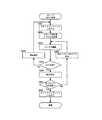
図3は、本発明の第1の実施形態の遊技機1の構成を示すブロック図である。
FIG. 3 is a block diagram showing a configuration of the
遊技機1は、遊技を統括的に制御する遊技制御装置500、各種演出を行うために表示
装置53及びスピーカ30等を制御する演出制御装置550、遊技球を払い出すために図
示しない払出モータを制御する払出制御装置580を備える。
The
まず、遊技制御装置500について説明する。図4では、演出制御装置550について
説明する。
First, the
遊技制御装置500は、遊技用マイコン501、入力I/F(Interface)5
05、出力I/F(Interface)506、及び外部通信端子507を備える。
The
05, an output I / F (Interface) 506, and an
遊技用マイコン501は、CPU502、ROM(Read Only Memory
)503及びRAM(Random Access Memory)504を備える。
The
) 503 and RAM (Random Access Memory) 504.
CPU502は、遊技を統括的に制御する主制御装置であって、遊技制御を司る。RO
M503は、遊技制御のための不変の情報(プログラム、データ等)を記憶している。R
AM504は、遊技制御時にワークエリアとして利用される。
The CPU 502 is a main control device that controls the game in an integrated manner, and controls the game. RO
M503 stores invariant information (program, data, etc.) for game control. R
The
外部通信端子507は、遊技制御装置500の設定情報等を検査する検査装置等の外部
機器に遊技制御装置500を接続する。
The
CPU502は、入力I/F505を介して各種入力装置(第1始動口SW45a、第
2始動口SW36d、一般入賞口SW44a、ゲートSW34a、カウントSW42d、
ガラス枠開放SW18a、前面枠開放SW3a、球切れSW54、振動センサ55、及び
磁気センサ56)からの検出信号を受けて、大当り抽選等、種々の処理を行う。
The CPU 502 receives various input devices (a first start port SW45a, a second start port SW36d, a general winning port SW44a, a gate SW34a, a count SW42d, via an input I / F 505).
Upon receiving detection signals from the glass
第1始動口SW45aは、第1始動入賞口45に遊技球が入賞したことを検出するスイ
ッチである。第2始動口SW36dは、普通変動入賞装置36の第2始動入賞口に遊技球
が入賞したことを検出するスイッチである。
The first
一般入賞口SWa44a〜44nは、一般入賞口44に遊技球が入賞したことを検出す
るスイッチである。ゲートSW34aは、普図始動ゲート34を遊技球が通過したことを
検出するスイッチである。
The general winning openings SWa 44 a to 44 n are switches that detect that a game ball has won the general winning
カウントSW42dは、特別変動入賞装置42の大入賞口に遊技球が入賞したことを検
出するスイッチである。
The count SW 42d is a switch that detects that a game ball has won a special winning opening of the special variable winning
ガラス枠開放SW18aは、ガラス枠18が開放されたことを検出するスイッチである
。前面枠開放SW3aは、前面枠3が開放されたことを検出するスイッチである。
The glass
球切れSW54は、遊技機1の内部に貯留され、払い出しに用いられる遊技球の数が所
定数以下になったことを検出するスイッチである。
The ball cut
振動センサ55は、遊技機1に与えられた振動を検出するセンサであり、遊技機1に振
動を与えて、不当に遊技球を獲得する不正を検出する。磁気センサ56は、第1始動入賞
口45、普通変動入賞装置36の第2始動入賞口、一般入賞口44、特別変動入賞装置4
2の大入賞口、及び普図始動ゲート34付近に設けられ、磁力を検出するセンサである。
磁気センサ93は、各入賞口付近に磁石を近づけて、遊技領域10aに発射された遊技球
を各入賞口に導く不正を検出する。
The
2 is a sensor that detects magnetic force and is provided in the vicinity of the two prize winning openings and the
The magnetic sensor 93 detects a fraud that brings a magnet close to each winning hole and guides a game ball launched to the
また、CPU502は、出力I/F506を介して、第1特図表示器38、第1特図記
憶表示器48、第2特図表示器39、第2特図記憶表示器49、普図表示器35、普電S
OL36b、大入賞口SOL42b、払出制御装置580、及び演出制御装置550に指
令信号を送信して、遊技を統括的に制御する。
In addition, the CPU 502 receives the first
A command signal is transmitted to the
第1特図表示器38には、第1始動入賞口45に遊技球が入賞した場合に補助遊技とし
て実行される第1特図変動表示ゲームが表示される。第1特図記憶表示器48には、所定
の上限数の範囲内で記憶される第1特図変動表示ゲームを開始する始動権利である第1始
動記憶数が表示される。
The first
第2特図表示器39には、普通変動入賞装置36の大入賞口に遊技球が入賞した場合に
補助遊技として実行される第2特図変動表示ゲームが表示される。第2特図記憶表示器4
9には、所定の上限数の範囲内で記憶される第2特図変動表示ゲームを開始する始動権利
である第2始動記憶数が表示される。
The second
In 9, a second start memory number that is a start right to start the second special figure variable display game stored within the range of the predetermined upper limit number is displayed.
普図表示器35には、遊技球が普図始動ゲート34を通過した場合に行われる普図変動
表示ゲームが表示される。
The
普電SOL36bは、普図表示器35で実行される普図変動表示ゲームの停止表示が特
別の結果態様となった場合に、開閉部材36a、36aを開放し、普通変動入賞装置36
の第2始動入賞口を遊技球が入賞しやすい状態にする。
The general
The second starting winning opening is made in a state where the game ball can easily win.
大入賞口SOL42bは、第1特図変動表示ゲーム又は第2特図変動表示ゲームの結果
が特別の結果態様となり、特別遊技状態となった場合に、特別変動入賞装置42の開閉扉
42aを開放して、大入賞口を遊技球が入賞しやすい状態に変換する。
The special winning opening SOL42b opens the open /
また、遊技制御装置500は、遊技機データを、外部情報端子508を介して、図示し
ない情報収集端末装置を介して、図示しない遊技場管理装置に出力する。遊技場管理装置
は、遊技場に設置された遊技機1の遊技データを収集管理する計算機である。
In addition, the
また、払出制御装置580は、遊技球が一般入賞口44又は大入賞口に入賞した場合に
、入賞した入賞口に対応する数の遊技球の払い出し、又は球貸ボタン26が操作された場
合に、所定数の遊技球の払い出しを行う払出指令を遊技制御装置500から受信した場合
に、受信した払出指令に基づいて、図示しない払出モータを制御する。なお、払出指令に
は、払い出す遊技球の数が含まれる。
In addition, the
遊技制御装置500は、変動開始コマンド、客待ちデモコマンド、ファンファーレコマ
ンド、確率情報コマンド、及びエラー指定コマンド等を、遊技の状況を示す遊技データと
して、出力I/F506を介して、演出制御装置550へ送信する。
The
図4は、本発明の第1の実施形態の演出制御装置550の構成を示すブロック図である
。
FIG. 4 is a block diagram showing a configuration of the
演出制御装置550は、遊技制御装置500から入力される遊技データに基づいて、演
出内容を決定して、表示装置53、及びスピーカ30を制御するとともに、装飾制御装置
610を介して装飾装置620、役物駆動SOL560(ソレノイド)、及び役物駆動M
OT(モータ)561を制御する。詳細は後述するが、これら装飾装置620、役物駆動
SOL560、及び役物駆動MOT561(総称して演出装置という)によって、遊技の
演出が行われる。また、演出制御装置550は、演出ボタン17から当該演出ボタン17
が操作されたことを示す信号が入力される。
The
The OT (motor) 561 is controlled. Although the details will be described later, a game effect is performed by the
A signal indicating that has been operated is input.
演出制御装置550は、CPU551、制御ROM552、RAM553、画像ROM
554、音ROM555、VDP556、音LSI557、入出力I/F558、電源投
入検出回路559、マスタIC570、及びNORゲート回路590を備える。
The
554,
CPU551は、遊技制御装置500に接続され、遊技制御装置500から指令信号が
割込信号(INT)として入力され、入力された指令信号に基づいて、各種演出を制御す
る主制御装置である。また、CPU551には、マスタIC570の後述するコントロー
ラ574から割込信号が入力されるとともに、VDP556から割込信号が入力される。
The
なお、CPU551に割込信号が入力されると、CPU551は、現在実行中の処理を
中断して、入力された割込信号に対応する処理を実行する。
When an interrupt signal is input to the
制御ROM552には、演出制御のための不変の情報(プログラム、データ等)が格納
されている。RAM553は、演出制御時にワークエリアとして利用される。
The
画像ROM554には、表示装置53に表示される画像データが格納され、画像ROM
554はVDP556に接続されている。音ROM555には、スピーカ30から出力さ
れる音データが格納され、音ROM555は音LSI557に接続されている。
The image ROM 554 stores image data to be displayed on the
554 is connected to the
VDP556は、表示装置53への画像出力を制御するプロセッサである。音LSI5
57は、スピーカ30からの音声出力を制御する回路である。
The
Reference numeral 57 denotes a circuit that controls the sound output from the
なお、VDP556は、表示装置53に表示される画像を更新する周期(33ms周期
)と同期する同期信号を発生させる同期信号発生手段を備える。同期信号発生手段は、同
期信号を発生させるごとに、発生させた同期信号をCPU551に割込信号として入力す
る。
Note that the
入出力I/F558は、演出ボタン17及びNORゲート回路590に接続されるイン
タフェースであり、演出ボタン17からの操作信号をCPU551へ伝達するとともに、
CPU551からのリセット信号をNORゲート回路590へ伝達する。
The input / output I /
A reset signal from the
なお、演出ボタン17は、上皿21の上縁部に設けられ、表示装置53で実行される第
1特図変動表示ゲーム又は第2特図変動表示ゲームにおける演出で、遊技者によって操作
される。
The
CPU551、VDP556、RAM553、制御ROM552、音LSI557、及
び入出力I/F558はバス563を介してそれぞれ接続されている。
The
電源投入検出回路559は、演出制御装置550に電源が投入された場合に、マスタI
C570の図示しないレジスタをデフォルト状態(すべて0)に初期化するリセット信号
を発生させ、発生させたリセット信号をNORゲート回路590へ出力する。
The power-on
A reset signal that initializes a register (not shown) of C570 to a default state (all 0s) is generated, and the generated reset signal is output to the NOR
また、CPU551は、所定の条件が成立した場合に、リセット信号をバス563を介
して入出力I/F558に出力し、入出力I/F558は入力されたリセット信号をNO
Rゲート回路590へ出力する。
The
Output to the
なお、電源投入検出回路559からNORゲート回路590へ入力されるリセット信号
、及びCPU551から入出力I/F558を介してNORゲート回路590へ入力され
るリセット信号は、いずれの場合にもロウレベルの状態である場合にリセットを指令する
信号として機能する。そのため、電源投入検出回路559及びCPU551の少なくとも
一方からNORゲート回路590にリセット信号が出力されていれば、NORゲート回路
590を介してリセット信号がマスタIC570に入力される。
Note that the reset signal input from the power-on
次に、マスタIC570について説明する。
Next, the
マスタIC570は、制御対象となる演出装置の装飾制御装置610のアドレスを指定
して、指定したアドレスの装飾制御装置610に演出装置の制御内容を出力する。
マスタIC570は、接続線Vcc、接続線Vact、接続線SDA、接続線SCL、
及び接続線GND(図5参照)の5本の接続線を介して、中継基板(装飾制御装置)60
0に接続される。
The
And the relay board (decoration control device) 60 via the five connection lines of the connection line GND (see FIG. 5).
Connected to 0.
接続線Vccは、中継基板600及び装飾制御装置610に、ロジック用の電源を供給
するための接続線である。接続線Vactは、演出装置を駆動させるための電源(例えば
、LEDを発光させるための電源)を供給するための接続線である。接続線SDAは、演
出制御装置550と装飾制御装置610との間でデータを通信するための接続線であり、
本実施形態におけるデータ線として機能する。接続線SCLは、接続線SDAでのデータ
通信に用いられるクロック信号を入出力するための接続線であり、本実施形態におけるタ
イミング信号線として機能する。図5に示す接続線GNDは、接続線Vcc及び接続線V
actで供給される電源のグランドである。
The connection line Vcc is a connection line for supplying logic power to the
It functions as a data line in this embodiment. The connection line SCL is a connection line for inputting and outputting a clock signal used for data communication through the connection line SDA, and functions as a timing signal line in the present embodiment. The connection line GND shown in FIG. 5 includes a connection line Vcc and a connection line V.
This is the ground of the power supplied by act.
中継基板600と装飾制御装置610との間は、マスタIC570と中継基板600と
の間と同じく、接続線Vcc、接続線Vact、接続線SDA、接続線SCL、及び接続
線GNDを介して接続される。
The
マスタIC570と装飾制御装置610とは、接続線SDA及び接続SCLによって2
ライン双方向通信を行う。
Line bi-directional communication.
マスタIC570は、中継基板600及び装飾制御装置610にデータを送信する場合
には、まず、接続線SCLの信号レベルをHIGHに維持したまま、接続線SDAの信号
レベルをHIGHからLOWに変化させることにより、装飾制御装置610へのデータ出
力を開始するためのスタート条件を成立させる(装飾制御装置610に対してスタートコ
ンディションを発行する)。
When transmitting data to the
この後、マスタIC570は、接続線SCLの信号レベルをLOWに変更し、接続線S
CLの信号レベルがLOWである間に接続線SDAの信号レベルを送信データの最初のビ
ットのレベルに設定し、所定時間後に接続線SCLの信号レベルをLOWからHIGHに
変化させる。接続線SCLの信号レベルがHIGHに変化すると、装飾制御装置610は
接続線SDAの信号レベルを取り込んで、送信データの最初のビットとして認識する。次
いで、マスタIC570は、接続線SCLの信号レベルをHIGHからLOWに戻す。
Thereafter, the
While the CL signal level is LOW, the signal level of the connection line SDA is set to the level of the first bit of the transmission data, and after a predetermined time, the signal level of the connection line SCL is changed from LOW to HIGH. When the signal level of the connection line SCL changes to HIGH, the
この手順を1回実行すると、マスタIC570から装飾制御装置610へ1ビットのデ
ータが送信され、最終的にはこの手順が8回繰り返されることで、送信データの8ビット
全てがマスタIC570から装飾制御装置610へ送信される(1バイト分のデータが送
信される)。
When this procedure is executed once, 1-bit data is transmitted from the
そして、マスタIC570は、最後の8ビット目のデータを送信し終えて、接続線SC
Lの信号レベルをHIGHからLOWに戻した際に、接続線SDAを解放して装飾制御装
置610からの返答信号を受信することを待機する受信待機状態にする。
Then, the
When the signal level of L is returned from HIGH to LOW, the connection line SDA is released to enter a reception standby state in which it waits to receive a response signal from the
受信待機状態になると、装飾制御装置610は、接続線SDAを介して1ビットの返答
信号(後述するACK又はNACK)をマスタIC570に返す。次いで、マスタIC5
70は、接続線SCLの信号レベルをLOWからHIGHに変化させて返答信号のレベル
を取り込み、所定時間後に接続線SCLの信号レベルをHIGHからLOWに変化させる
と、装飾制御装置610は接続線SDAを解放する。
In the reception standby state, the
70 changes the signal level of the connection line SCL from LOW to HIGH to capture the level of the response signal, and after a predetermined time, changes the signal level of the connection line SCL from HIGH to LOW, the
マスタIC570は、このような1バイト分のデータ送信と1ビット分の返答信号の受
信とを交互に繰り返し、装飾制御装置610へ出力すべきデータがすべて出力されるまで
継続する。マスタIC570は、出力すべきデータの出力が終了した場合には、接続線S
CLの信号レベルをHIGHに維持したまま、接続線SDAの信号レベルをLOWからH
IGHに変更させることにより、装飾制御装置610へのデータ出力を終了するためのス
トップ条件を成立させる(装飾制御装置610に対してストップコンディションを発行す
る)。
The
The signal level of the connection line SDA is changed from LOW to H while the CL signal level is kept HIGH.
By changing to IGH, a stop condition for ending data output to the
入力用BUF571は、装飾制御装置610から接続線SDAを介して入力されたデー
タが一時的に記憶される記憶装置である。
The
具体的には、マスタIC570が入力モードに設定された場合において、装飾制御装置
610からマスタIC570に送信されたデータが、フィルタ575Aによりノイズが除
去されて入力用BUF571に一時的に記憶される。
Specifically, when the
出力用BUF572は、装飾制御装置610に接続線SDAを介して出力するデータが
一時的に記憶される。
The
リセットREG573は、バス563に接続され、CPU551からの指令を受けてリ
セット信号をコントローラ574に出力する。コントローラ574は、マスタIC570
を統括的に制御し、各種処理を実行する。
The
To perform overall processing and execute various processes.
フィルタ575Aは、接続線SDAから入力されたデータのノイズを除去する。ドライ
バ576Aは、接続線SDAからデータを出力する場合に、トランジスタ578Aが動作
可能な電圧をトランジスタ578Aに印加する。
The
図9に示すように接続線SDAには、プルアップ抵抗Rによって所定の電圧が印加され
て、接続線SDAはフィルタ575A及びトランジスタ578Aに接続されている。
As shown in FIG. 9, a predetermined voltage is applied to the connection line SDA by the pull-up resistor R, and the connection line SDA is connected to the
トランジスタ578Aは、電力消費を抑えるために電界効果トランジスタ(FET)が
用いられており、トランジスタ578Aのゲートはドライバ576Aに接続され、ドレイ
ンはプルアップ抵抗Rにより所定の電圧が印加された接続線SDAに接続され、ソースは
接地されている。
The
トランジスタ578Aのゲートに印加される電圧がトランジスタ578Aを動作させる
所定値よりも小さければ、ドレインとソースとの間に電流が流れないので、接続線SDA
に印加された電圧は降下せず、その結果、接続線SDAはHIGHレベルとなる。一方、
トランジスタ578Aのゲートに印加される電圧がトランジスタ578Aを動作させる所
定値以上であれば、所定値の電圧が印加されたドレインから接地されているソースへ電流
が流れることによって、接続線SDAの電圧が低下し、その結果、接続線SDAはLOW
レベルとなる。
If the voltage applied to the gate of the
As a result, the connection line SDA becomes HIGH level. on the other hand,
If the voltage applied to the gate of the
Become a level.
なお、トランジスタ578Aは、10ミリアンペア程度の電流をドレインからソースへ
流しても破損しない仕様のものを用いている。このため、接続線SDAには、通常のI2
Cバス使用で用いられる電流値よりもはるかに大きい10ミリアンペア程度の電流を流す
ことが可能であり、演出制御装置550と装飾制御装置610との間のデータ送信が、ノ
イズによる障害に耐えうる構成となっている。
Note that the
It is possible to pass a current of about 10 milliamperes that is much larger than the current value used when using the C bus, and the data transmission between the
ドライバ576Aは、データを接続線SDAから出力する場合に、トランジスタ578
Aにドレインとソースとの間に電流を流すためにトランジスタ578Aのゲートにトラン
ジスタ578Aが動作可能な値の電圧を印加する。そして、ドライバ576Aは、接続線
SDAの電圧を、HIGHレベル又はLOWレベルに設定することによって、データを接
続線SDAから出力する。
When the
In order to cause a current to flow between the drain and the source in A, a voltage having a value at which the
また、フィルタ575Bは、接続線SCLから入力されたデータのノイズを除去する。
ドライバ576Bは、接続線SCLからデータを出力する場合に、トランジスタ578B
が動作可能な電圧をトランジスタ578Bに印加する。
The
When the
Is applied to the
図9に示すように接続線SCLは、プルアップ抵抗Rによって所定の電圧が印加されて
、接続線SDAはフィルタ575B及びトランジスタ578Bに接続されている。
As shown in FIG. 9, a predetermined voltage is applied to the connection line SCL by the pull-up resistor R, and the connection line SDA is connected to the
トランジスタ578Bは、電力消費を抑えるために電界効果トランジスタ(FET)が
用いられており、トランジスタ578Bのゲートはドライバ576Bに接続され、ドレイ
ンはプルアップ抵抗Rにより所定の電圧が印加された接続線SCLに接続され、ソースは
接地されている。
The
トランジスタ578Bのゲートに印加される電圧がトランジスタ578Bを動作させる
所定値よりも小さければ、ドレインとソースとの間に電流が流れないので、接続線SCL
に印加された電圧は降下せず、その結果、接続線SCLはHIGHレベルとなる。一方、
トランジスタ578Bのゲートに印加される電圧がトランジスタ578Bを動作させる所
定値以上であれば、所定値の電圧が印加されたドレインから接地されているソースへ電流
が流れることによって、接続線SCLの電圧が低下し、その結果、接続線SCLはLOW
レベルとなる。
If the voltage applied to the gate of the
As a result, the connection line SCL becomes HIGH level. on the other hand,
If the voltage applied to the gate of the
Become a level.
なお、トランジスタ578Bは、10ミリアンペア程度の電流をドレインからソースへ
流しても破損しない仕様のものを用いている。そのため、接続線SCLには、通常のI2
Cバス使用で用いられる電流値よりもはるかに大きい10ミリアンペア程度の電流を流す
ことが可能であり、演出制御装置550と装飾制御装置610との間のデータ送信が、ノ
イズによる障害に耐えうる構成となっている。
Note that the
It is possible to pass a current of about 10 milliamperes that is much larger than the current value used when using the C bus, and the data transmission between the
ドライバ576Bは、クロック信号を接続線SCLから出力する場合に、トランジスタ
578Bにドレインとソースとの間に電流を流すためにトランジスタ578Bのゲートに
トランジスタ578Bが動作可能な値の電圧を印加する。そして、ドライバ576Bは、
接続線SCLの電圧を、HIGHレベルとLOWレベルとに繰り返し変化させることによ
って、クロック信号を接続線SCLから出力する。
When the
A clock signal is output from the connection line SCL by repeatedly changing the voltage of the connection line SCL between a HIGH level and a LOW level.
電源投入リセット回路577は、マスタIC570に電源が投入されて、電源投入リセ
ット回路577内の電圧が所定値に達した場合に、入力用BUF571及び出力用BUF
572などの記憶領域をデフォルト状態にするためのリセット信号をコントローラ574
に出力する。
The power-on
The controller 574 receives a reset signal for setting a storage area such as 572 to a default state.
Output to.
次に、中継基板600及び装飾制御装置610について説明する。
Next, the
なお、中継基板600は、装飾制御装置610のうちマスタIC570に直接接続され
る、つまり最も上流側に位置するものである。
The
装飾装置620は、装飾制御装置610に設けたI2CI/Oエクスパンダ615(図
6で後述)によって制御され、電流を流すことによって光が点滅して演出を行う発光装置
であり、例えばLEDなどで構成される。役物駆動ソレノイド(SOL)560は、電流
が流れると往復動作する装置であり、遊技盤10に配置される図示しない装飾のための役
物を可動させて演出を行う。役物駆動モータ(MOT)561は、電流が流れると回転動
作する装置であり、可動役物60を可動させて演出を行う。役物駆動ソレノイド(SOL
)560及び役物駆動モータ(MOT)561も、装飾制御装置610に設けたI2CI
/Oエクスパンダ615によって制御される。
The
) 560 and character object drive motor (MOT) 561 also provided in the decorative controller 610 I 2 CI
Controlled by the /
なお、役物駆動SOL560が可動役物60を可動させてもよいし、役物駆動MOT5
61が図示しない役物を可動させてもよい。
The
61 may move an unillustrated accessory.
演出制御装置550と中継基板600との接続方法、及び中継基板600と中継基板6
00以外の装飾制御装置610との接続方法は、図5で詳細を説明する。装飾制御装置6
10は、図6〜図10で詳細を説明する。
Method for connecting
The connection method with the
10 will be described in detail with reference to FIGS.
図5は、本発明の第1の実施形態の装飾制御装置610A〜610Fの接続の説明図で
ある。なお、説明の都合上、装飾制御装置610として、1個の中継基板600と、6個
の装飾制御装置610A〜610Fを図示しているが、実際には、遊技機の仕様に対応し
て必要な数の装飾制御装置610が接続されている。
FIG. 5 is an explanatory diagram of connections of the
演出制御装置550は、接続線Vcc、接続線Vact、接続線SDA、接続線SCL
、及び接続線GND(以下、この5本の接続線を一つのハーネスという)を介して演出制
御装置550と接続される。
The
And the connection line GND (hereinafter, these five connection lines are referred to as one harness) and connected to the
中継基板600には、二つの装飾制御装置610A及び610Dがそれぞれハーネスに
よって並列に接続される。
Two
装飾制御装置610Aにはハーネスを介して装飾制御装置610Bが接続され、装飾制
御装置610Bにはハーネスを介して装飾制御装置610Cが接続される。
The
一方、装飾制御装置610Dにはハーネスを介して装飾制御装置610Eが接続され、
装飾制御装置610Eにはハーネスを介して装飾制御装置610Fが接続される。
On the other hand, a
The
各装飾制御装置610は、ハーネスを自身に接続するための取付口となるコネクタを備
える。このコネクタは各装飾制御装置610で共通であるので、接続線を接続順の誤配線
を防止できる。
Each
ここで、装飾制御装置610に設けたI2CI/Oエクスパンダ615(図6で後述)
が装飾装置620を制御する方法について説明する。
Here, an I 2 CI /
Describes a method of controlling the
演出制御装置550は、遊技制御装置500から入力された遊技データに基づいて、演
出装置の出力態様を決定する。そして、演出制御装置550は、決定された出力態様とな
るように、制御対象となる装飾制御装置610の個別アドレス(I2CI/Oエクスパン
ダ615の個別アドレス)を含む演出制御データ(演出制御情報)を中継基板600に出
力する。このとき、演出制御データは、中継基板600を介して演出制御装置550に接
続されるすべての装飾制御装置610に対して接続線SDAから出力される。このため、
マスタIC570は、マスタIC570に接続されるすべての装飾制御装置610を制御
可能である。
The
The
なお、本実施形態では演出装置としてLED等の発光装置を例示しているので、LED
の発光態様が演出装置の出力態様に相当する。この場合、演出制御データによって、LE
Dの点灯/点滅/消灯が指示され、同時に、LEDの点滅周期や点灯輝度も指示される。
In the present embodiment, a light-emitting device such as an LED is illustrated as the rendering device, so the LED
The light emission mode corresponds to the output mode of the rendering device. In this case, LE is determined by the production control data.
The lighting / flashing / extinguishing of D is instructed, and at the same time, the flashing cycle and lighting brightness of the LED are instructed.
各装飾制御装置610には、一意な個別アドレスが予め設定されているので、演出制御
データが入力されると、入力された演出制御データに含まれるアドレスと設定されている
個別アドレスとが一致するか否かを判定する。そして、入力された演出制御データに含ま
れるアドレスと設定されている個別アドレスとが一致すると判定された場合には、装飾制
御装置610のI2CI/Oエクスパンダ615は、演出制御データを取り込んで、対応
する装飾装置620の出力態様を制御するとともに、8ビット目のデータが入力された直
後に返答信号をマスタIC570に出力する。
Each
なお、各装飾制御装置610には、個別アドレス以外にも、装飾制御装置610のI2
CI/Oエクスパンダ615を初期化するためのリセット用アドレスが設定されている。
このリセットアドレスは、全てのI2CI/Oエクスパンダ615に対して共通に設けら
れたアドレスであり、個別アドレスとして使用することは不可能となっている。また、こ
のリセットアドレスの値を変更することもできないようになっている(詳細は後述する)
。
Each
A reset address for initializing the CI /
This reset address is an address provided in common to all the I 2 CI /
.
演出制御装置550は、装飾制御装置610(正確には、装飾制御装置610のI2C
I/Oエクスパンダ615)を初期化する場合に、このリセット用の共通アドレスを含ん
だ初期化指示データを、中継基板600に出力する。このとき、初期化指示データ演出制
御データは、中継基板600を介して、演出制御装置550に接続されるすべての装飾制
御装置610に対して接続線SDAから出力される。
The
When the I / O expander 615) is initialized, initialization instruction data including the common address for resetting is output to the
各装飾制御装置610には、リセット用の共通アドレスが予め設定されているので、入
力されたデータに含まれるアドレスと、予め設定されているリセット用の共通アドレスと
が一致するか否かを判定する。入力されたデータに含まれるアドレスと、予め設定されて
いるリセット用の共通アドレスとが一致すると判定された場合には、装飾制御装置610
のI2CI/Oエクスパンダ615は、返答信号をマスタIC570に出力するとともに
、入力されたデータを初期化指示データとして取り込み、I2CI/Oエクスパンダ61
5自身を初期化する。
Each
The I 2 CI /
5 Initialize itself.
なお、I2CI/Oエクスパンダ615が初期化されると、当該初期化されたI2CI/
Oエクスパンダ615によって制御される演出装置はオフ状態となる。
Incidentally, the I 2 CI /
The rendering device controlled by the
このように、装飾制御装置610は、演出制御装置550からの指令に基づく制御を行
うので、演出制御装置550と装飾制御装置610との関係は、演出制御装置550のマ
スタIC570がマスタであり、装飾制御装置610のI2CI/Oエクスパンダ615
がスレーブである。
As described above, the
Is a slave.
図5では、装飾制御装置610の制御対象が装飾装置620である場合について説明し
たが、装飾制御装置610の制御対象が役物駆動SOL560や役物駆動MOT561で
あってもよい。この場合、演出装置がモータやソレノイドなどの駆動源となることから、
これらの駆動源の動作態様が、演出装置の出力態様に相当することになる。この場合、演
出制御データによって、駆動源の作動/停止が指示され、同時に動作速度も指示される。
Although the case where the decoration target of the
The operation mode of these drive sources corresponds to the output mode of the rendering device. In this case, activation / deactivation of the drive source is instructed by the effect control data, and the operation speed is also instructed at the same time.
図6は、本発明の第1の実施形態の装飾制御装置610のブロック図である。
FIG. 6 is a block diagram of the
図6では、装飾制御装置610の内部に装飾装置620であるLEDを備える装飾制御
装置610(図6の下側の装飾制御装置610)と、外部の装飾装置620に接続される
装飾制御装置610(図6の中央の装飾制御装置610)と、について説明する。
In FIG. 6, the decoration control device 610 (the
まず、装飾制御装置610の内部にLEDを備える装飾制御装置610について説明す
る。
First, the
図6の下側の装飾制御装置610は、I2CI/Oエクスパンダ615及びLED(装
飾装置20)を備える。接続線SDA及び接続線SCLは、装飾制御装置610内で二つ
に分岐し、一方は、そのまま次の装飾制御装置610に出力される。他方は、I2CI/
Oエクスパンダ615に接続される。
The
Connected to
また、I2CI/Oエクスパンダ615の出力側には、制御対象となる装飾装置620
が接続される。I2CI/Oエクスパンダ615の出力側は、図7で説明するポート0〜
15によって構成される。さらに、装飾制御装置610のすべてのポートが、図8Aで後
述する電流制限抵抗R0〜R15を介して、内部のLEDに接続されている。なお、この
電流制限抵抗R0〜R15も、装飾制御装置610に備えられている。
Further, a
Is connected. The output side of the I 2 CI /
15. Furthermore, all the ports of the
前述したように、I2CI/Oエクスパンダ615は、演出制御装置550から入力さ
れた演出制御データに含まれるアドレスと、当該I2CI/Oエクスパンダ615に設定
されている個別アドレスとが一致する場合にのみ、演出制御データに含まれる装飾データ
に基づいて、I2CI/Oエクスパンダ615に接続されている装飾装置620を制御す
る。
As described above, the I 2 CI /
なお、図中の電源Vledは、図5で前述した接続線Vactにより供給される電源(
LEDを発光させるための電源)に相当するものである。
Note that the power supply Vled in the figure is a power supply (supplied by the connection line Vact described in FIG.
This corresponds to a power source for causing the LED to emit light.
次に、外部の装飾装置620に接続される装飾制御装置610について説明する。
Next, the
図6の中央の装飾制御装置610は、I2CI/Oエクスパンダ615及びLED(装
飾装置20)を備え、装飾制御装置610の外部に接続される装飾装置基板625に備わ
るLEDに電流を流すための接続線、装飾装置基板625のLEDに電源電圧Vledを
供給する接続線、及び、グランドに接地する接続線を介して、装飾制御装置610と装飾
装置基板625とが接続される。
The central
装飾装置基板625は、I2CI/Oエクスパンダ615を備えておらず、LEDのみ
を備えた基板である。この場合、装飾装置基板625に備えたLEDに接続される電流制
限抵抗(図8A)を、装飾装置基板625に設けることになるが、I2CI/Oエクスパ
ンダ615が備えられた装飾制御装置610に設けてもよい。
The
なお、装飾装置基板625に設けたLEDの数に対応して、装飾制御装置610から装
飾装置基板625へ渡されることになる、これらのLEDに電流を流すための接続線の数
が決定される。例えば、装飾装置基板625に二つのLEDを備えた場合には、I2CI
/Oエクスパンダ615のポートと対応するLEDとを接続するための2本の制御線と、
Vledを供給する電源線が1本とが、少なくとも必要となる。
It should be noted that the number of connection lines for passing current to these LEDs to be passed from the
Two control lines for connecting the port of the /
At least one power supply line for supplying Vled is required.
そして、中央の装飾制御装置610に設けられたI2CI/Oエクスパンダ615も、
演出制御装置550から入力された演出制御データに含まれるアドレスと、当該I2CI
/Oエクスパンダ615に設定されている個別アドレスとが一致する場合にのみ、演出制
御データに含まれる装飾データに基づいて、I2CI/Oエクスパンダ615に接続され
ている装飾装置620を制御する。この場合、中央の装飾制御装置610に設けられた装
飾装置620と、装飾装置基板625に設けられた装飾装置620の両方が、I2CI/
Oエクスパンダ615によって制御される。
And the I 2 CI /
The address included in the effect control data input from the
The
Controlled by
このように、装飾装置基板625を設けて、装飾制御装置610から一部の装飾装置(
LED)を分離させることで、離れた箇所に配置されたLEDであっても、共通のI2C
I/Oエクスパンダ615により制御することができる。
In this way, the
LED) is separated, and even if the LEDs are arranged at remote locations, the common I 2 C
It can be controlled by the I /
なお、装飾制御装置610は、装飾装置620の代わりに、役物駆動SOL560や役
物駆動MOT561を接続し、これらを制御してもよいが、詳細は、図8Bで後述する。
Note that the
図7は、本発明の第1の実施形態のI2CI/Oエクスパンダ615のブロック図であ
る。
FIG. 7 is a block diagram of the I 2 CI /
I2CI/Oエクスパンダ615は、接続線SDAに接続されるトランジスタ630、
接続線SDAに接続されるフィルタ631、接続線SDAに接続されるドライバ632、
接続線SCLに接続されるフィルタ633、バスコントローラ634、出力設定レジスタ
635、出力コントローラ636、I2CI/Oエクスパンダ615の出力側の各ポート
0〜15に接続されるドライバ637、各ポート0〜15に接続されるトランジスタ63
8A〜638P、及びリセット信号発生回路639を備える。
The I 2 CI /
A
A
8A to 638P and a reset
フィルタ631は、接続線SDAに接続され、接続線SDAから入力されたデータのノ
イズを除去し、ノイズが除去されたデータをバスコントローラ634に出力する。ドライ
バ632は、返答信号を接続線SDAから出力する場合に、トランジスタ630が動作可
能な電圧をトランジスタ630に印加する。
The
ドライバ632は、接続線SDAからデータ(返答信号)を出力する場合に、トランジ
スタ630が動作可能な電圧をトランジスタ630に印加する。
When the
トランジスタ630は、電力消費を抑えるために電界効果トランジスタ(FET)が用
いられており、トランジスタ630のゲートはドライバ632に接続され、ドレインはプ
ルアップ抵抗R(図4参照)により所定の電圧が印加された接続線SDAに接続され、ソ
ースは接地されている。
The
トランジスタ630のゲートに印加される電圧がトランジスタ630を動作させる所定
値よりも小さければ、ドレインとソースとの間に電流が流れない。一方、トランジスタ6
30のゲートに印加される電圧がトランジスタ630を動作させる所定値以上であれば、
所定値の電圧が印加されたドレインから接地されているソースへ電流が流れることによっ
て、接続線SDAの電圧が低下する。なお、トランジスタ630は、10ミリアンペア程
度の電流をドレインからソースへ流しても破損しない仕様のものを用いている。
If the voltage applied to the gate of the
If the voltage applied to the gate of 30 is not less than a predetermined value for operating the
When a current flows from the drain to which a predetermined voltage is applied to the grounded source, the voltage of the connection line SDA decreases. Note that the
ドライバ632は、データ(返答信号)を接続線SDAから出力する場合に、トランジ
スタ630にドレインとソースとの間に電流を流すためにトランジスタ630のゲートに
トランジスタ630が動作可能な値の電圧を印加する。そして、ドライバ632は、接続
線SDAの電圧をHIGHからLOWへ繰り返し変化させることによって、データを接続
線SDAから出力する。
When the
フィルタ633は、接続線SCLに接続され、接続線SCLから入力されたデータのノ
イズを除去し、ノイズが除去されたデータをバスコントローラ634に出力する。
The
また、I2CI/Oエクスパンダ615には、当該I2CI/Oエクスパンダ615に備
わるアドレス設定用端子A0〜A3によって固有のアドレスが設定されており、バスコン
トローラ634に入力されている。さらに、I2CI/Oエクスパンダ615をリセット
するためのアドレスも、予め設定されている。
In addition, the I 2 CI /
バスコントローラ634は、接続線SDAから入力されたデータのアドレスがI2CI
/Oエクスパンダ615に設定された固有のアドレスと一致するか否かを判定し、一致し
ている場合に当該データを演出制御データとして取り込む。
In the
It is determined whether or not the address matches the unique address set in the /
また、バスコントローラ634は、接続線SDAから入力されたデータのアドレスがI
2CI/Oエクスパンダ615に予め設定されたリセット用のアドレスと一致するか否か
を判定し、入力されたデータのアドレスとI2CI/Oエクスパンダ615に予め設定さ
れたリセット用のアドレスとが一致している場合に当該データを初期化指示データとして
取り込み、当該I2CI/Oエクスパンダ615を初期化する。
In addition, the
It is determined whether or not it matches the reset address preset in the 2 CI /
また、バスコントローラ634は、SCL接続線の信号レベルのLOWからHIGHへ
の変化回数が8回に達し8ビット目のデータを取り込んだ後、SCL接続線の信号レベル
がHIGHからLOWへ変化すると、返答信号を接続線SDAからマスタIC570に出
力する。さらに、SCL接続線の信号レベルがLOWからHIGHへ変化することが確認
され、再度SCL接続線の信号レベルがHIGHからLOWへ変化すると、接続線SDA
を開放する。つまり、SCL接続線の信号レベルのLOWからHIGHへの変化回数が9
回になるタイミングで返答信号を出力する。
In addition, the
Is released. That is, the number of changes in the signal level of the SCL connection line from LOW to HIGH is 9
A response signal is output at the time of turning.
出力設定レジスタ635には、当該I2CI/Oエクスパンダ615の動作モードやポ
ート0〜15の出力状態が設定される。バスコントローラ634が接続線SDAから初期
化指示データを取り込んで、当該I2CI/Oエクスパンダ615が初期化された場合に
は、出力設定レジスタ635は、すべてのポート0〜15に電流が流れないように初期状
態に設定される。
In the
出力コントローラ636は、出力設定レジスタ635に設定されたデータに基づいて、
ポートドライバ637を介して、各ポート0〜15に接続された演出装置に電流を流すこ
とによって、演出装置の出力状態を実際に制御する。この出力状態は、バスコントローラ
634が接続線SDAから演出制御データを取り込むと、取り込んだ演出制御データに指
定されている内容に更新される。
The
The output state of the effect device is actually controlled by flowing current through the
ドライバ637は、ポートに電流を流す場合に、電流を流すポートに接続されるトラン
ジスタ638A〜638Pが動作可能な電圧を当該トランジスタに印加する。
When a current flows through a port, the
トランジスタ638A〜638Pのゲートはドライバ637に接続され、ドレインは図
8A及び図8Bに示すように演出装置を動作させるための電圧が印加された接続線に接続
するポート端子に接続され、ソースは接地されている。
The gates of the
トランジスタ638A〜638Pのゲートに印加される電圧がトランジスタ638A〜
638Pを動作させる所定値よりも小さければ、ドレインとソースとの間に電流が流れな
い。一方、638A〜638Pのゲートに印加される電圧がトランジスタ638を動作さ
せる所定値以上であれば、図8Aに示す電源Vled、又は図8Bに示す電源Vmotや
電源Vsolからゲートに印加されている所定の電圧が、トランジスタ638のドレイン
を介して接地されているソースへ電流が流れることによって、ポート端子に接続された演
出装置の出力状態を制御できる。
The voltage applied to the gates of the
If it is smaller than a predetermined value for operating 638P, no current flows between the drain and the source. On the other hand, if the voltage applied to the gates of 638A to 638P is equal to or higher than a predetermined value for operating the transistor 638, the power supply Vled shown in FIG. 8A or the power supply Vmot or the power supply Vsol shown in FIG. Current flows to the source grounded through the drain of the transistor 638, so that the output state of the effect device connected to the port terminal can be controlled.
また、装飾制御装置610のI2CI/Oエクスパンダ615は、I2CI/Oエクスパ
ンダ615のポート端子に接続された全ての演出装置を同時期に制御することが可能であ
るので、I2CI/Oエクスパンダ615のポート端子に接続された一つの演出装置を一
つのグループとして制御することができる。
Further, the I 2 CI /
そして、各装飾制御装置610に備わるI2CI/Oエクスパンダ615同士は、互い
に異なる個別アドレスが割り当てられているので、演出装置が複数のグループに分割され
た形態となっている。即ち、各装飾制御装置610に備わるI2CI/Oエクスパンダ6
15は、演出装置をグループ単位で制御可能なグループ単位制御手段として構成されてい
るものである。
Since the I 2 CI /
15 is configured as a group unit control means capable of controlling the effect device in units of groups.
従って、装飾制御装置610を統括する演出制御装置550は、グループ単位制御手段
を統括して制御するグループ統括制御手段として機能している。
Therefore, the
リセット信号発生回路639には、I2CI/Oエクスパンダ615に電源を供給する
接続線Vccと接続されるVcc端子、及び外部からのリセット信号を受け付けるRES
ET端子が接続されている。
The reset
The ET terminal is connected.
リセット信号発生回路639は、I2CI/Oエクスパンダ615に電源が投入され、
電圧が所定値まで立ち上がった場合、リセット信号を発生させ、発生させたリセット信号
をバスコントローラ634、出力設定レジスタ635、及び出力コントローラ636に入
力する。
The reset
When the voltage rises to a predetermined value, a reset signal is generated, and the generated reset signal is input to the
なお、外部からLOWレベルのリセット信号が入力された場合には、リセット信号発生
回路639はリセット信号を出力するので、演出制御装置550のCPU551から、N
ORゲート回路5590を経由して、RESET端子からリセット信号を入力するように
してもよい。RESET端子を使用しない場合は、図8A及び図8Bに示すようにRES
ET端子はHIGHにプルアップされていてもよい。
When a reset signal of LOW level is input from the outside, the reset
A reset signal may be input from the RESET terminal via the OR gate circuit 5590. When the RESET terminal is not used, as shown in FIGS. 8A and 8B, RES
The ET terminal may be pulled up to HIGH.
図8Aは、本発明の第1の実施形態の装飾装置620を制御する装飾制御装置610の
I2CI/Oエクスパンダ615周辺の回路図である。
FIG. 8A is a circuit diagram around the I 2 CI /
I2CI/Oエクスパンダ615は、入力端子としてNC端子、RESET端子、SC
L端子、SDA端子、Vcc端子、A0〜A3端子、及びGND端子を備え、出力端子と
して、PORT0〜PORT15を備える。
The I 2 CI /
L terminal, SDA terminal, Vcc terminal, A0 to A3 terminal, and GND terminal are provided, and PORT0 to PORT15 are provided as output terminals.
RESET端子には、プルアップ抵抗Rを介してI2CI/Oエクスパンダ615に供
給される電源が接続されている。このため、リセット端子に印加される電圧は常にHIG
Hに維持されている。
A power source supplied to the I 2 CI /
H is maintained.
SCL端子は接続線SCLに接続され、SDA端子は接続線SDAに接続される。 The SCL terminal is connected to the connection line SCL, and the SDA terminal is connected to the connection line SDA.
Vcc端子には、I2CI/Oエクスパンダ615に供給される電源が接続される。ま
た、Vcc端子には、電源ノイズを除去するコンデンサCPが接続される。
A power supply supplied to the I 2 CI /
A0端子〜A3端子は、I2CI/Oエクスパンダ615に固有のアドレスを設定する
ための端子である。なお、通常I2CI/Oエクスパンダ615のアドレスは、4ビット
で表現され、この端子にI2CI/Oエクスパンダ615の電源が印加されている場合に
はバスコントローラ634に「1」が設定され、この端子がグランドに接続されている場
合にはバスコントローラ634に「0」が設定される。
The A0 to A3 terminals are terminals for setting unique addresses for the I 2 CI /
したがって、図8Aに示すI2CI/Oエクスパンダ615のアドレスは「0100」
であり、図8Bに示すI2CI/Oエクスパンダ615のアドレスは「0110」である
。GND端子は、電圧をグランドするための端子である。
Therefore, the address of the I 2 CI /
The address of the I 2 CI /
各PORT0端子〜PORT15端子は、電流制限抵抗R0〜R15を介して各LED
0〜LED15からなる装飾装置620に接続される。なお、PORT0にように、ポー
ト1個に対して1個のLEDを接続してもよいが、PORT1〜15のように、ポート1
個に対して複数個のLEDを接続してもよい。
Each PORT0 terminal to PORT15 terminal is connected to each LED via current limiting resistors R0 to R15.
0 to a
A plurality of LEDs may be connected to each.
全てのポートにLEDを1個ずつ設ける場合は、1個のI2CI/Oエクスパンダ61
5によって、最大で16個のLEDを制御できることになる。また、各ポートに接続され
るLEDの個数が異なる場合は、1個のポートに直列に接続された全てのLEDを1種類
のLEDということにすれば、1個のI2CI/Oエクスパンダ615によって、最大で
16種類のLEDを制御できることになる。
One I 2 CI / O expander 61 when one LED is provided for each port
5 can control a maximum of 16 LEDs. If the number of LEDs connected to each port is different, assuming that all LEDs connected in series to one port are one type of LED, one I 2 CI / O expander is used. By 615, up to 16 kinds of LEDs can be controlled.
PORT0端子〜PORT15端子に接続されるトランジスタ638A〜638P(図
7参照)のゲートに対してドライバ637から電圧が印加されると、電圧が印加されたト
ランジスタ638A〜638Pのドレインからソースへ電流が流れることが可能になり、
PORT0端子〜PORT15端子に接続されるLED0〜LED15に電流が流れ、各
LED0〜LED15は点灯する。
When a voltage is applied from the
A current flows through the
一方、ドライバ637がトランジスタ638A〜638Pのゲートに電圧を印加しなけ
れば、各LED0〜LED15に電流が流れない状態になり、各LED0〜LED15は
点灯しない。
On the other hand, if the
なお、I2CI/Oエクスパンダ615のPORT0端子〜PORT15端子には、L
EDの代わりに、モーターやソレノイドを接続することも可能であるので、I2CI/O
エクスパンダ615を用いて、モーターやソレノイドを駆動する場合について説明する。
Note that the PORT0 to PORT15 terminals of the I 2 CI /
Since it is possible to connect a motor or solenoid instead of ED, I 2 CI / O
A case where a motor or a solenoid is driven using the
図8Bは、本発明の第1の実施形態の役物駆動MOT561及び役物駆動SOL560
を制御する装飾制御装置610のI2CI/Oエクスパンダ615周辺の回路図である。
FIG. 8B illustrates the
6 is a circuit diagram around the I 2 CI /
役物駆動MOT561はステッピングモータにより構成され、ステッピングモータを駆
動する各相の信号端子に、所定の電圧を順次印加することで回動する。本実施形態では、
役物駆動MOT561の各相の信号端子が、PORT0端子〜PORT3端子に接続され
る。
The
The signal terminal of each phase of the
役物駆動MOT561に接続されているPORT0端子〜PORT3端子に接続される
トランジスタ638A〜638Dのいずれかのゲートに対してドライバ637から電圧が
印加されると、電圧が印加されたトランジスタ638A〜638Dのドレインからソース
へ電流が流れることが可能になり、PORT0端子〜PORT3端子に接続される役物駆
動MOT561に電流が流れ、役物駆動MOT561が駆動する。
When a voltage is applied from the
なお、各PORT0端子〜PORT3端子と役物駆動MOT561とを接続する接続線
は分岐し、分岐した一方の接続線は、役物駆動MOT561に供給される電源にダイオー
ドD及びツェナダイオードZDを介して接続される。
The connection lines connecting the PORT0 terminal to the PORT3 terminal and the
また、PORT端子15は、役物駆動SOL560に接続される。役物駆動SOL56
0に接続されているPORT15端子に接続されるトランジスタ638Pのゲートに対し
てドライバ637から電圧が印加されると、電圧が印加されたトランジスタ638Pのド
レインからソースへ電流が流れることが可能になり、PORT15端子に接続される役物
駆動SOL560に電流が流れ、役物駆動SOL560が駆動する。
The
When a voltage is applied from the
なお、図8Bでは、I2CI/Oエクスパンダ615に役物駆動MOT561及び役物
駆動SOL560の双方が接続されているが、一つのI2CI/Oエクスパンダ615に
対して、役物駆動MOT561及び役物駆動SOL560の少なくとも一方だけを接続し
た構成でもよい。
In FIG. 8B, with respect to I 2 CI / O Aix although both character object drive MOT561 and character object
例えば、ステッピングモーターだけを制御するグループとしてのI2CI/Oエクスパ
ンダ615を専用に設けたり、ソレノイドだけを制御するグループとしてのI2CI/O
エクスパンダ615を専用に設けるようにしてもよい。このような構成により、同一グル
ープに属する演出装置を同じタイミングで制御することが可能となるので、高速処理が必
要な演出装置だけをグループ化して効率よく制御することも可能となる。
For example, a dedicated I 2 CI /
The
図9は、本発明の第1の実施形態の中継基板600の入出力に関する接続線の回路図で
ある。
FIG. 9 is a circuit diagram of connection lines related to input / output of the
中継基板600は、上流コネクタ601、二つの下流コネクタ602A、602B、及
びI2CI/Oエクスパンダ615を備える。
The
上流コネクタ601は中継基板600よりも上流のマスタIC570に接続されるコネ
クタであり、コネクタ602A、602Bは、中継基板600よりも下流の装飾制御装置
610に接続される。
The
二つの下流コネクタ602A、602Bに接続線SDAを接続するために、上流コネク
タ601から延びる内部接続線SDA911は分岐901で第1接続線SDA921と第
2接続線SDA931とに分岐する。第1接続線SDA921は下流コネクタ602Aに
接続され、第2接続線SDA931は下流コネクタ602Bに接続される。
In order to connect the connection line SDA to the two
同じく、上流コネクタ601から延びる内部接続線SCL912は分岐902で第1接
続線SCL922と第2接続線SCL932とに分岐する。第1接続線SCL922は下
流コネクタ602Aに接続され、第2接続線SCL932は下流コネクタ602Bに接続
される。
Similarly, the internal connection line SCL912 extending from the
接続線SDAをI2CI/Oエクスパンダ615に接続するために、第2接続線SDA
931は分岐903で分岐し、分岐した第2接続線SDA931はI2CI/Oエクスパ
ンダ615の図8A及び図8に示すSDA端子に接続される。また、接続線SCLをI2
CI/Oエクスパンダ615に接続するために、第2接続線SCL932は分岐904で
分岐し、分岐した第2接続線SCL932はI2CI/Oエクスパンダ615の図8A及
び図8Bに示すSCL端子に接続される。
In order to connect the connection line SDA to the I 2 CI /
931 branches at a
In order to connect to the CI /
なお、I2CI/Oエクスパンダ615には、I2CI/Oエクスパンダ615の電源電
圧となる電圧Vccが供給されている。また、図9では図示されていないが、I2CI/
Oエクスパンダ615からは、中継基板600に設けたLED(装飾装置200)を駆動
する各ポート0〜15の信号線(図8A参照)が出力されている。
Note that the I 2 CI /
From the
また、I2CI/Oエクスパンダ615は、第2接続線SDA931及び第2接続線S
CL932が接続されるとしたが、第1接続線SDA921及び第1接続線SCL922
に接続されてもよい。
The I 2 CI /
Although the
May be connected.
I2CI/Oエクスパンダ615が上流のマスタIC570に接続線SDAを介して出
力する信号、及び上流のマスタIC570から中継基板600のI2CI/Oエクスパン
ダ615へ接続線SDAを介して入力される信号のノイズを除去するために、内部接続線
SDA911にはツェナダイオードZD941が接続されている。
I 2 CI / O
具体的には、内部接続線SDA911は分岐905で分岐し、分岐した内部接続線SD
A911はツェナダイオードZD941のカソード側に接続され、ツェナダイオードZD
941のアノード側は接地されている。
Specifically, the internal connection line SDA911 branches at the
A911 is connected to the cathode side of the Zener diode ZD941, and the Zener diode ZD94
The anode side of 941 is grounded.
このため、内部接続線SDA911に印加された所定以上の電圧(例えば、パルス性の
ノイズ信号)は、ツェナダイオードZD941によって逃がされる。
For this reason, a voltage (for example, a pulsed noise signal) higher than a predetermined voltage applied to the internal connection line SDA911 is released by the Zener diode ZD941.
また、上流のマスタIC570から中継基板600のI2CI/Oエクスパンダ615
へ接続線SCLを介して入力される信号のノイズを除去するために、内部接続線SCL9
12にはツェナダイオードZD942が接続されている。
Further, the
In order to remove noise from the signal input via the connection line SCL, the internal connection line SCL9
12 is connected to a Zener diode ZD942.
具体的には、内部接続線SCL912は分岐906で分岐し、分岐した内部接続線SC
L912はツェナダイオードZD942のカソード側に接続され、ツェナダイオードZD
942のアノード側は接地されている。
Specifically, the internal connection line SCL912 branches at a branch 906, and the branched internal connection line SC.
L912 is connected to the cathode side of the Zener diode ZD942, and the Zener diode ZD94
The anode side of 942 is grounded.
このため、内部接続線SCL912に印加された所定以上の電圧(例えば、パルス性の
ノイズ信号)は、ツェナダイオードZD942によって逃がされる。
For this reason, a voltage (for example, a pulsed noise signal) applied to the internal connection line SCL912 is released by the Zener diode ZD942.
中継基板600のI2CI/Oエクスパンダ615が下流コネクタ602Aに接続され
た装飾制御装置610に接続線SDAを介して出力する信号、及び下流コネクタ602A
に接続された装飾制御装置610から中継基板600のI2CI/Oエクスパンダ615
へ接続線SDAを介して入力される信号のノイズを除去するために、第1接続線SDA9
21にはツェナダイオードZD943が接続されている。
A signal output from the I 2 CI /
I 2 CI /
In order to remove noise from the signal input to the connection line SDA, the first connection line SDA9
A zener diode ZD943 is connected to 21.
具体的には、第1接続線SDA921は分岐907で分岐し、分岐した第1接続線SD
A921はツェナダイオードZD943のカソード側に接続され、ツェナダイオードZD
943のアノード側は接地されている。
Specifically, the first connection line SDA921 branches off at the
A921 is connected to the cathode side of Zener diode ZD943, and Zener diode ZD
The anode side of 943 is grounded.
このため、内部接続線SDA921に印加された所定以上の電圧(例えば、パルス性の
ノイズ信号)は、ツェナダイオードZD943によって逃がされる。
Therefore, a voltage (for example, a pulsed noise signal) higher than a predetermined voltage applied to the internal connection line SDA921 is released by the Zener diode ZD943.
また、第1接続線SDA921に接続されるツェナダイオードZD943と同じく、第
2接続線SDA931にもツェナダイオード945が接続される。
Similarly to the Zener diode ZD943 connected to the first connection line SDA921, the
また、中継基板600のI2CI/Oエクスパンダ615から下流コネクタ602Aに
接続された装飾制御装置610へ接続線SCLを介して入力される信号のノイズを除去す
るために、第1接続線SCL922にはツェナダイオードZD944が接続されている。
The first connection line SCL922 is used to remove noise of a signal input from the I 2 CI /
具体的には、第1接続線SCL922は分岐908で分岐し、分岐した第1接続線SC
L922はツェナダイオードZD944のカソード側に接続され、ツェナダイオードZD
944のアノード側は接地されている。
Specifically, the first
L922 is connected to the cathode side of the Zener diode ZD944 and the Zener diode ZD
The anode side of 944 is grounded.
このため、内部接続線SCL922に印加された所定以上の電圧(例えば、パルス性の
ノイズ信号)は、ツェナダイオードZD944によって逃がされる。
For this reason, a voltage (for example, a pulse noise signal) of a predetermined level or higher applied to the internal connection line SCL922 is released by the Zener diode ZD944.
また、第1接続線SCL922に接続されるツェナダイオードZD944と同じく、第
2接続線SCL932にもツェナダイオードZD946が接続される。
Similarly to the Zener diode ZD944 connected to the first connection line SCL922, the Zener diode ZD946 is also connected to the second connection line SCL932.
また、マスタIC570に接続される上流側の接続線SDA、及び装飾制御装置610
に接続される下流側の接続線SDAの電圧をプルアップするためのプルアップ抵抗R95
1が、第1接続線SDA921に接続される。同じく、マスタIC570に接続される上
流側の接続線SCL、及び装飾制御装置610に接続される下流側の接続線SCLの電圧
をプルアップするためのプルアップ抵抗R952が、第1接続線SDA922に接続され
る。
Further, the upstream connection line SDA connected to the
Pull-up resistor R95 for pulling up the voltage of the downstream connection line SDA connected to
1 is connected to the first connection line SDA921. Similarly, a pull-up resistor R952 for pulling up the voltage of the upstream connection line SCL connected to the
具体的には、第1接続線SDA921は分岐909で分岐し、分岐した第1接続線SD
A921はプルアップ抵抗R951に接続される。同じく第1接続線SCL922は分岐
910で分岐し、分岐した第1接続線SCL922はプルアップ抵抗R952に接続され
る。
Specifically, the first connection line SDA921 branches at the
A921 is connected to a pull-up resistor R951. Similarly, the first connection line SCL922 branches at a
なお、接続線SDA及び接続線SCLの電圧をプルアップするプルアップ抵抗951、
952は、中継基板600が備えなくてもよく、マスタIC570が備えてもよいし、中
継基板600以外の装飾制御装置610が備えてもよい。要するに、接続線SDA及び接
続線SCLを駆動するトランジスタのドレインの端子に、電圧Vccを供給できる箇所で
あれば、どこでもよい。
A pull-up
952 may not be provided in the
中継基板600のI2CI/Oエクスパンダ615に電源電圧を供給する接続線Vcc
に接続される上流コネクタ601のVcc端子から延びる内部接続線Vcc971と、上
流コネクタ601のGND端子から延び、接地されている内部接続線GND972とは、
平滑コンデンサC961及びバイパスコンデンサ962を介して接続されている。
Connection line Vcc for supplying a power supply voltage to the I 2 CI /
The internal connection line Vcc971 extending from the Vcc terminal of the
They are connected via a smoothing capacitor C961 and a
平滑コンデンサC961は、電源の電圧波形を滑らかにするためのコンデンサであり、
バイパスコンデンサCP962は、電源の電圧のノイズを除去するためのコンデンサであ
る。
The smoothing capacitor C961 is a capacitor for smoothing the voltage waveform of the power supply,
The bypass capacitor CP962 is a capacitor for removing noise from the power supply voltage.
このため、中継基板600のI2CI/Oエクスパンダ615に供給される電源電圧は
、平滑コンデンサC961により電圧が平滑化され、バイパスコンデンサ962によりノ
イズが除去されて、I2CI/Oエクスパンダ615に供給される。
For this reason, the power supply voltage supplied to the I 2 CI /
同じく、下流コネクタ602A、602BのVcc端子から延びる内部接続線Vcc9
73と、GND端子から延びる内部接続線GND974とは、平滑コンデンサC961及
びバイパスコンデンサ962を介して接続されている。これによって、平滑化され、ノイ
ズが除去された電圧が下流の装飾制御装置610に接続される接続線Vccに印加される
。
Similarly, the internal connection line Vcc9 extending from the Vcc terminal of the
73 and the internal connection line GND974 extending from the GND terminal are connected via a smoothing capacitor C961 and a
図10は、本発明の第1の実施形態の装飾制御装置610の入出力に関する接続線の回
路図である。
FIG. 10 is a circuit diagram of connection lines related to input / output of the
装飾制御装置610は、上流コネクタ611、I2CI/Oエクスパンダ615、及び
下流コネクタ612を備える。
The
上流コネクタ611には、中継基板600又は上流側の装飾制御装置610からバスが
接続される。下流コネクタ612には、下流側の装飾制御装置610に接続するバスが接
続される。
A bus is connected to the
上流コネクタ611のSDA端子と下流コネクタ612のSDA端子とは、内部接続線
SDA1011によって接続されている。また、上流コネクタ611のSCL端子と下流
コネクタ612のSCL端子とは、内部接続線SCL1012によって接続されている。
The SDA terminal of the
接続線SDAをI2CI/Oエクスパンダ615に接続するために、内部接続線SDA
1011は分岐1001で分岐し、分岐した内部接続線SDA1011はI2CI/Oエ
クスパンダ615の図8A及び図8に示すSDA端子に接続される。また、接続線SCL
をI2CI/Oエクスパンダ615に接続するために、内部接続線SCL1012は分岐
1002で分岐し、分岐した内部接続線SCL1012はI2CI/Oエクスパンダ61
5の図8A及び図8Bに示すSCL端子に接続される。
In order to connect the connection line SDA to the I 2 CI /
Reference numeral 1011 branches at the
Are connected to the I 2 CI /
5 is connected to the SCL terminal shown in FIGS. 8A and 8B.
なお、I2CI/Oエクスパンダ615には、I2CI/Oエクスパンダ615の電源電
圧となる電圧Vccが供給されている。また、図10では図示されていないが、I2CI
/Oエクスパンダ615からは、当該装飾制御装置610に係わるLED(装飾装置20
0)を駆動する各ポート0〜15の信号線(図8A参照)が出力されている。
Note that the I 2 CI /
From the /
The signal lines (see FIG. 8A) of the
図10に示す装飾制御装置610のI2CI/Oエクスパンダ615が上流コネクタ6
11に接続された上流の装飾制御装置610又は中継基板600に接続線SDAを介して
出力する信号、及び上流コネクタ611に接続された上流の装飾制御装置610又は中継
基板600から図10に示す装飾制御装置610のI2CI/Oエクスパンダ615へ接
続線SDAを介して入力される信号のノイズを除去するために、内部接続線SDA101
1にはツェナダイオードZD1041が接続されている。
The I 2 CI /
10 from the upstream
1 is connected to a Zener diode ZD1041.
具体的には、内部接続線SDA1011は分岐1003で分岐し、分岐した内部接続線
SDA1011はツェナダイオードZD1041のカソード側に接続され、ツェナダイオ
ードZD1041のアノード側は接地されている。
Specifically, the internal connection line SDA1011 branches at a branch 1003, the branched internal connection line SDA1011 is connected to the cathode side of the Zener diode ZD1041, and the anode side of the Zener diode ZD1041 is grounded.
このため、内部接続線SDA1011に印加された所定以上の電圧(例えば、パルス性
のノイズ信号)は、ツェナダイオードZD1041によって逃がされる。
For this reason, a voltage (for example, a pulsed noise signal) higher than a predetermined voltage applied to the internal connection line SDA1011 is released by the Zener diode ZD1041.
また、上流コネクタ611に接続される上流の装飾制御装置610又は中継基板600
から図10に示す装飾制御装置610のI2CI/Oエクスパンダ615へ接続線SCL
を介して入力される信号のノイズを除去するために、内部接続線SCL1012にはツェ
ナダイオードZD942が接続されている。
Further, the upstream
To the I 2 CI /
Zener diode ZD942 is connected to the internal connection line SCL1012 in order to remove noise from the signal input through the internal connection line SCL1012.
具体的には、内部接続線SCL1012は分岐1004で分岐し、分岐した内部接続線
SCL1012はツェナダイオードZD1042のカソード側に接続され、ツェナダイオ
ードZD1042のアノード側は接地されている。
Specifically, the internal connection line SCL1012 branches at a branch 1004, the branched internal connection line SCL1012 is connected to the cathode side of the Zener diode ZD1042, and the anode side of the Zener diode ZD1042 is grounded.
このため、内部接続線SCL1012に印加された所定以上の電圧(例えば、パルス性
のノイズ信号)は、ツェナダイオードZD1042によって逃がされる。
For this reason, a voltage (for example, a pulsed noise signal) applied to the internal
図10に示す装飾制御装置610のI2CI/Oエクスパンダ615が下流コネクタ6
12に接続された下流の装飾制御装置610に接続線SDAを介して出力する信号、及び
下流コネクタ612に接続された下流の装飾制御装置610から図10に示す装飾制御装
置のI2CI/Oエクスパンダ615へ接続線SDAを介して入力される信号のノイズを
除去するために、内部接続線SDA1011にはツェナダイオードZD1043が接続さ
れている。
The I 2 CI /
10, a signal output via the connection line SDA to the downstream
具体的には、内部接続線SDA1011は分岐1005で分岐し、分岐した内部接続線
SDA1011はツェナダイオードZD1043のカソード側に接続され、ツェナダイオ
ードZD1043のアノード側は接地されている。
Specifically, the internal connection line SDA1011 branches at a
このため、内部接続線SDA1011に印加された所定以上の電圧(例えば、パルス性
のノイズ信号)は、ツェナダイオードZD1043によって逃がされる。
For this reason, a voltage (for example, a pulse noise signal) of a predetermined level or more applied to the internal connection line SDA1011 is released by the Zener diode ZD1043.
また、図10に示す装飾制御装置610のI2CI/Oエクスパンダ615から下流コ
ネクタ612に接続された下流の装飾制御装置610へ接続線SCLを介して入力される
信号のノイズを除去するために、内部接続線SCL1012にはツェナダイオードZD1
044が接続されている。
Further, in order to remove noise of a signal input via the connection line SCL from the I 2 CI /
044 is connected.
具体的には、内部接続線SCL1012は分岐1006で分岐し、分岐した内部接続線
SCL1012はツェナダイオードZD1044のカソード側に接続され、ツェナダイオ
ードZD1044のアノード側は接地されている。
Specifically, the internal connection line SCL1012 branches at a
このため、内部接続線SCL1012に印加された所定以上の電圧(例えば、パルス性
のノイズ信号)は、ツェナダイオードZD1044によって逃がされる。
For this reason, a voltage (for example, a pulse noise signal) applied to the internal
装飾制御装置610のI2CI/Oエクスパンダ615に電源電圧を供給する接続線V
ccに接続される上流コネクタ611のVcc端子から延びる内部接続線Vcc1071
と、上流コネクタ611のGND端子から延び、接地されている内部接続線GND107
2とは、平滑コンデンサC1061及びバイパスコンデンサ1062を介して接続されて
いる。
Connection line V for supplying power supply voltage to the I 2 CI /
Internal connection line Vcc1071 extending from the Vcc terminal of
And the internal connection line GND107 extending from the GND terminal of the
2 is connected via a smoothing capacitor C1061 and a
平滑コンデンサC1061は図9に示す平滑コンデンサC961と同じコンデンサであ
り、バイパスコンデンサCP1062は図9に示すバイパスコンデンサ962と同じコン
デンサである。
The smoothing capacitor C1061 is the same capacitor as the smoothing capacitor C961 shown in FIG. 9, and the bypass capacitor CP1062 is the same capacitor as the
また、下流コネクタ612のVcc端子から延びる内部接続線Vcc1073と、GN
D端子から延びる内部接続線GND1074とは、平滑コンデンサC1061及びバイパ
スコンデンサ1062を介して接続されている。
Further, an internal
The internal
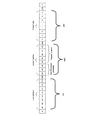
図11は、本発明の第1の実施形態の演出制御装置550から装飾制御装置610に出
力されるデータに含まれるスレーブアドレス1100の説明図である。
FIG. 11 is an explanatory diagram of the
スレーブアドレス1100は、上位3ビットからなる固定アドレス部1101及び下位
5ビットからなる可変アドレス部1102を含む。
The
固定アドレス部1101は、「110」が予め設定されていて、I2CI/Oエクスパ
ンダ615が変更できないアドレスである。
The fixed
可変アドレス部1102は、I2CI/Oエクスパンダ615に設定可能なアドレスで
あり、制御対象となるI2CI/Oエクスパンダ615のA0〜A3の端子に設定されて
いるパターンに対応した4ビットのI2CI/Oエクスパンダアドレス1103と、当該
データが読み出し要求であるのか書き込み要求であるのかを示す1ビットのR/W識別デ
ータ1104と、が含まれる。
演出制御装置550から装飾制御装置610に出力される演出制御データは、書き込み
要求であるので、R/W識別データ1104には、通常「0」が登録される。
Since the effect control data output from the
図12は、本発明の第1の実施形態のI2CI/Oエクスパンダアドレステーブル12
00の説明図である。
FIG. 12 shows the I 2 CI / O expander address table 12 according to the first embodiment of this invention.
FIG.
I2CI/Oエクスパンダアドレステーブル1200は、マスタIC570によって管
理されるテーブルである。I2CI/Oエクスパンダアドレステーブル1200は、スレ
ーブアドレス1201とI2CI/Oエクスパンダアドレス1202との対応関係を示し
ている。
The I 2 CI / O expander address table 1200 is a table managed by the
スレーブアドレス1201には、演出制御装置550により送受信の対象として指定さ
れる装飾制御装置610のスレーブアドレスが格納されている。スレーブアドレスは、図
13で前述したように、上位3ビットからなる固定アドレス部と、4ビットのI2CI/
Oエクスパンダアドレスと、1ビットのR/W識別データとを組み合わせて構成される。
The
It is configured by combining an O expander address and 1-bit R / W identification data.
I2CI/Oエクスパンダアドレス1202には、図8Aや図8Bで前述したように、
各スレーブアドレスに対応する4ビットのI2CI/Oエクスパンダアドレスが登録され
る。
In the I 2 CI /
A 4-bit I 2 CI / O expander address corresponding to each slave address is registered.
ただし、I2CI/Oエクスパンダアドレスのうち、アドレス「1000」及びアドレ
ス「1011」は、各I2CI/Oエクスパンダ615を相互に識別するための固有のア
ドレスとしては使用できない。
However, among the I 2 CI / O expander addresses, the address “1000” and the address “1011” cannot be used as unique addresses for identifying the I 2 CI /
「1000」は、すべての装飾制御装置610に対する指令を出力する場合に指定され
るアドレス(オールコールアドレス)の電源投入時のデフォルト値として用いられる。「
1011」はソフトウェアによって、マスタIC570に接続されている全ての装飾制御
装置610を無条件にリセットする場合に用いられる共通アドレスである。
“1000” is used as a default value at the time of power-on of an address (all call address) specified when outputting commands to all the
“1011” is a common address used when all the
このように、装飾制御装置610のI2CI/Oエクスパンダ615に設定可能な固有
アドレスは14個であるために、演出制御装置550は、14個のI2CI/Oエクスパ
ンダ615を制御できる。また、一つの装飾制御装置610は、PORT0〜PORT1
5を備えるので、16個(言い換えれば16種類)のLEDを制御できる。よって、演出
制御装置550は、224個(言い換えれば224種類)のLEDを制御できる。
As described above, since there are 14 unique addresses that can be set in the I 2 CI /
Since 5 are provided, 16 (in other words, 16 types) LEDs can be controlled. Therefore, the
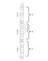
図13は、本発明の第1の実施形態のI2CI/Oエクスパンダ615に備わる出力設
定レジスタ635(図7参照)に割り当てられたワークレジスタを説明するための図であ
る。
FIG. 13 is a diagram for explaining a work register assigned to the output setting register 635 (see FIG. 7) included in the I 2 CI /
I2CI/Oエクスパンダ615の出力設定レジスタ635には、ワークレジスタ(デ
バイスレジスタ)と、コントロールレジスタ(制御レジスタ)とが割り当てられている。
ワークレジスタは、I2CI/Oエクスパンダ615に対して予め定義されている設定を
行うための情報や、I2CI/Oエクスパンダ615に接続されている演出装置(例えば
、LED)の出力態様を特定するための情報を記憶するものである。また、コントロール
レジスタは、ワークレジスタへのデータ書き込み手順を規定する情報を記憶するもである
。
A work register (device register) and a control register (control register) are assigned to the
Work register, and information for setting the predefined relative I 2 CI /
なお、図13に示すように、ワークレジスタは、複数の情報を異なる記憶領域に分散し
て記憶する構成となっており、各記憶領域毎に異なるレジスタ番号が付与されている。
As shown in FIG. 13, the work register has a configuration in which a plurality of pieces of information are distributed and stored in different storage areas, and different register numbers are assigned to the respective storage areas.
レジスタ番号が「00h」となる記憶領域には、「MODE1」というレジスタ名が付
与されており、また、レジスタ番号が「01h」となる記憶領域には、「MODE2」と
いうレジスタ名が付与されている。レジスタ番号「00h」及び「01h」の記憶領域に
値が書き込まれると、書き込まれた値に基づいて、I2CI/Oエクスパンダ615の初
期設定が行われる。
A register name “MODE1” is assigned to the storage area with the register number “00h”, and a register name “MODE2” is assigned to the storage area with the register number “01h”. Yes. When values are written in the storage areas of the register numbers “00h” and “01h”, the I 2 CI /
レジスタ番号が「02h」〜「11h」となる記憶領域には、「PWM0」〜「PWM
15」というレジスタ名が付与されている。レジスタ番号「02h」〜「11h」の記憶
領域のいずれかに値が書き込まれると、I2CI/Oエクスパンダ615に接続される発
光装置を構成する16個のLEDのうち、値が書き込まれたレジスタ番号に対応するLE
Dの輝度が、書き込まれた値に基づいて調整される。例えば、レジスタ番号「02h」の
記憶領域に値が書き込まれた場合には、図8Aに示すポート0に接続されたLED0の輝
度が調整される。
In the storage areas where the register numbers are “02h” to “11h”, “PWM0” to “PWM
The register name “15” is assigned. When a value is written in any of the storage areas of register numbers “02h” to “11h”, the value is written out of the 16 LEDs constituting the light emitting device connected to the I 2 CI /
The brightness of D is adjusted based on the written value. For example, when a value is written in the storage area of the register number “02h”, the luminance of the
なお、I2CI/Oエクスパンダ615に役物駆動SOL560が接続される場合には
、役物駆動SOL560が接続されるポートに対応するレジスタ番号の記憶領域には、役
物駆動SOL560を通電して作動するか、通電せずに未作動状態にするかを示す値が書
き込まれる。
When the
また、I2CI/Oエクスパンダ615に役物駆動MOT561が接続される場合には
、役物駆動MOT561が接続されるポートに対応するレジスタ番号の記憶領域には、役
物駆動MOT561の目標回転位置を示す値が書き込まれる。
When the
レジスタ番号が「12h」となる記憶領域には、「GRPPWM」というレジスタ名が
付与され、レジスタ番号が「13h」となる記憶領域には、「GRPFREQ」というレ
ジスタ名が付与されている。レジスタ番号「12h」及び「13h」の記憶領域に値が書
き込まれると、書き込まれた値に基づいて、全体のLED(16個のLED)の点滅パタ
ーンが設定される。
A register name “GRPPWM” is assigned to the storage area with the register number “12h”, and a register name “GRPFREQ” is assigned to the storage area with the register number “13h”. When a value is written in the storage areas of the register numbers “12h” and “13h”, a blinking pattern of all LEDs (16 LEDs) is set based on the written value.
具体的には、レジスタ番号「12h」の記憶領域に値が書き込まれた場合には、全体の
LEDのオン・オフ比率であるデューティサイクルが設定され、レジスタ番号「13h」
の記憶領域に値が書き込まれた場合には、全体のLEDの点滅周期が設定される。
Specifically, when a value is written in the storage area of the register number “12h”, the duty cycle that is the on / off ratio of the entire LED is set, and the register number “13h” is set.
When a value is written in the storage area, the blinking cycle of the entire LED is set.
レジスタ番号が「14h」となる記憶領域には、「LEDOUT0」というレジスタ名
が付与されている。レジスタ番号「14h」の記憶領域に値が書き込まれると、書き込ま
れた値に基づいて、LED0〜LED3の出力状態が設定される。
A register name “LEDOUT0” is given to the storage area where the register number is “14h”. When a value is written in the storage area of the register number “14h”, the output states of the
レジスタ番号が「15h」となる記憶領域には、「LEDOUT1」というレジスタ名
が付与されている。レジスタ番号「15h」の記憶領域に値が書き込まれると、書き込ま
れた値に基づいて、LED4〜LED7の出力状態が設定される。
A register name “LEDOUT1” is given to the storage area where the register number is “15h”. When a value is written in the storage area of the register number “15h”, the output states of the
レジスタ番号が「16h」となる記憶領域には、「LEDOUT2」というレジスタ名
が付与されている。レジスタ番号「16h」の記憶領域に値が書き込まれると、書き込ま
れた値に基づいて、LED8〜LED11の出力状態が設定される。
A register name “LEDOUT2” is assigned to the storage area where the register number is “16h”. When a value is written in the storage area of the register number “16h”, the output states of the
レジスタ番号が「17h」となる記憶領域には、「LEDOUT3」というレジスタ名
が付与されている。レジスタ番号「17h」の記憶領域に値が書き込まれると、書き込ま
れた値に基づいて、LED12〜LED15の出力状態が設定される。
A register name “LEDOUT3” is given to the storage area where the register number is “17h”. When a value is written in the storage area of the register number “17h”, the output states of the
レジスタ番号が「18h」〜「1Ah」となる記憶領域には、「SUBADR1」〜「
SUBADR3」というレジスタ名が付与されている。レジスタ番号「18h」〜「1A
h」の記憶領域に値が書き込まれると、書き込まれた値に基づいて、第1サブアドレス〜
第3サブアドレスが設定される。
In the storage areas where the register numbers are “18h” to “1Ah”, “SUBADR1” to “
The register name “SUBADR3” is assigned. Register numbers “18h” to “1A
When a value is written in the storage area of “h”, the first sub-address to
A third subaddress is set.
レジスタ番号が「1Bh」となる記憶領域には、「ALLCALLADR」というレジ
スタ名が付与されている。レジスタ番号「1Bh」の記憶領域に値が書き込まれると、書
き込まれた値に基づいて、オールコールアドレスが設定される。
A register name “ALLCALLADR” is given to the storage area whose register number is “1Bh”. When a value is written in the storage area of the register number “1Bh”, an all-call address is set based on the written value.
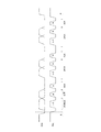
図14は、本発明の第1の実施形態のマスタIC570が接続線SDA及び接続線SC
Lを介して出力するデータのスタート条件及びストップ条件の説明図である。
FIG. 14 shows that the
It is explanatory drawing of the start condition and stop condition of the data output via L.
接続線SCLは、データの非送信時に信号レベルがHIGHになっており、マスタIC
570は、装飾制御装置610にデータを出力する際に、接続線SCLの信号レベルをL
OWからHIGHに変化させ、装飾制御装置610が接続線SDAのデータを取り込むた
めのストローブ信号として作用させる。
The connection line SCL has a signal level HIGH when data is not transmitted, and the master IC
When 570 outputs data to the
The
接続線SDAは、データの非送信時に信号レベルがHIGHになっており、接続線SC
Lのクロック信号に合わせて接続線SDAからデータが出力される。
The connection line SDA has a signal level HIGH when data is not transmitted, and the connection line SC
Data is output from the connection line SDA in accordance with the L clock signal.
マスタIC570は、接続線SCLの信号レベルをHIGHに維持したまま、接続線S
DAの信号レベルをHIGHからLOWに変化させることで、データの出力が開始するこ
とを示すスタート条件となる信号を出力する。
The
By changing the DA signal level from HIGH to LOW, a signal serving as a start condition indicating that data output starts is output.
装飾制御装置610のI2CI/Oエクスパンダ615は、接続線SDA及び接続線S
CLからスタート条件となる信号が入力されると、データの出力が開始することを把握す
る。
The I 2 CI /
When a signal serving as a start condition is input from CL, it is understood that data output starts.
マスタIC570は、接続線SCLの信号レベルをHIGHに維持したまま、接続線S
DAの信号レベルをLOWからHIGHに変化させることで、データの出力が終了するこ
とを示すストップ条件を示す信号を出力する。
The
By changing the DA signal level from LOW to HIGH, a signal indicating a stop condition indicating the end of data output is output.
装飾制御装置610のI2CI/Oエクスパンダ615は、ストップ条件が入力される
と、データの出力が終了することを把握する。
The I 2 CI /
図15は、本発明の第1の実施形態のマスタIC570から出力されたデータが入力さ
れた装飾制御装置610が返答信号を出力するタイミングチャートである。
FIG. 15 is a timing chart at which the
装飾制御装置610は、スタート条件が成立してから接続線SCLの信号レベルの変化
回数を計数し、接続線SCLのクロック信号に合わせて接続線SDAから入力されるデー
タを取り込む。
The
そして、装飾制御装置610は、スタート条件が成立してから接続線SCLの信号レベ
ルの変化回数が9回に達する直前に、返答信号をマスタIC570に接続線SDAを介し
て出力する。換言すると、装飾制御装置610は、接続線SDAから8ビット目のデータ
を取り込んだ後に、接続線SCLの信号レベルがHIGHからLOWに変化することを契
機に、返答信号を当該接続線SDAを介して出力する。
Then, the
なお、図に示すように、データの受信に成功したことを示す返答信号(ACKの返答信
号)はLOWレベルによって示され、データの受信に失敗したことを示す返答信号(NA
CKの返答信号、図ではACK出力なしに相当)はHIGHレベルによって示される。
As shown in the figure, a response signal (ACK response signal) indicating that the data has been successfully received is indicated by a LOW level, and a response signal (NA) indicating that the data reception has failed.
The CK response signal (corresponding to no ACK output in the figure) is indicated by a HIGH level.
また、マスタIC570は、スタート条件が成立してから接続線SCLの信号レベルが
8回変化すると、接続線SDAを解放することによって、装飾制御装置610から返答信
号の入力を待機する。そして、マスタIC570は、接続線SDAを解放したまま、接続
線SCLの信号レベルを変化させて、装飾制御装置610からの返答信号を取り込む。
Further, when the signal level of the connection line SCL changes eight times after the start condition is satisfied, the
図16は、本発明の第1の実施形態のマスタIC570が演出制御データを出力する場
合の接続線SDA及び接続線SCLの信号レベルのタイミングチャートである。
FIG. 16 is a timing chart of signal levels of the connection line SDA and the connection line SCL when the
まず、マスタIC570は、データの出力を開始する場合には、接続線SCLの信号レ
ベルをHIGHに維持したまま、接続線SDAの信号レベルをHIGHからLOWに変化
させることによって、スタート条件を示す信号を出力し、これからデータを出力すること
を装飾制御装置610に通知する。
First, when starting output of data, the
次に、マスタIC570は、合計7ビットからなる制御対象となる装飾制御装置610
のスレーブアドレスを出力する。次に、マスタIC570は、読み出し要求である書き込
み要求であるかを示すデータを8ビット目に出力する。
Next, the
Outputs the slave address. Next, the
そして、マスタIC570は、接続線SCLの信号レベルが9回目にHIGHになると
きに、装飾制御装置610から返答信号が入力されるので、ACKの返答信号であれば接
続線SDAの信号レベルがLOWに変化し、NACKの返答信号であれば接続線SDAの
信号レベルがHIGHに変化する。
The
次に、マスタIC570は、アドレスデータの出力後、データを、8の倍数となるビッ
ト数で出力する。マスタIC570は、データの8ビット目を出力した後、ACKの返答
信号が入力されるのを待ってデータの9ビット目を出力する。以降、8の倍数番目に相当
するビットのデータを出力すると、ACKの返答信号が入力されるのを確認してから、(
8の倍数+1)番目のビットを出力し、全データが出力されるまで繰り返す。
Next, after outputting the address data, the
Output a multiple of 8 + 1) -th bit and repeat until all data is output.
なお、マスタIC570は、データの8の倍数番目となるビットを出力した後、所定時
間経過してもACKの返答信号が入力されない場合には、データの送信に失敗したものと
みなして、再度スタート条件を送信する。次いで、接続線SDAを介して、再度アドレス
データを出力し、ACKの返答信号を確認しながら、もう一度、データを1ビット目から
出力する。
If the
また、マスタIC570は、データの最後のビットのデータを出力した後、ACKの返
答信号が入力されるのを待って、ストップ条件を示す信号を出力する。
The
なお、図16では、スタート条件を示す信号を出力してからストップ条件を示す信号を
出力するまでの間に、合計24ビット(スレーブアドレス8ビット、データ16ビット)
のデータを出力しているが、24ビット以上であってもよいし、24ビット以下であって
もよい。
In FIG. 16, there is a total of 24 bits (
However, it may be 24 bits or more or 24 bits or less.
図17は、本発明の第1の実施形態のマスタIC570が、スレーブの個別アドレスを
指定して装飾制御装置610に演出制御データを設定する場合において、マスタIC57
0とI2CI/Oエクスパンダ615との間で授受されるデータのフォーマットを説明す
る図である。
FIG. 17 shows the master IC 57 when the
FIG. 6 is a diagram illustrating a format of data exchanged between 0 and an I 2 CI /
はじめに出力される8ビットのデータ1801には、データ送信の対象となる装飾制御
装置610のアドレス「A0〜A6」と、当該データが読み出し要求であるのか書き込み
要求であるのかを示す1ビットのR/W識別データとが含まれる。このアドレス「A0〜
A6」のうち、「A4〜A6」は値「110」となる固定アドレス部であり、「A0〜A
3」はI2CI/Oエクスパンダ615のA0〜A3の端子に設定されているアドレスに
相当する(図8参照)。なお、このデータ1801は、図16における「ADRESS」
及び「R/W」に対応するものである。
The 8-
Among “A6”, “A4 to A6” are fixed address portions having a value “110”, and “A0 to A6”.
“3” corresponds to the address set in the terminals A0 to A3 of the I 2 CI / O expander 615 (see FIG. 8). The
And “R / W”.
次に、出力される8ビットのデータ1802には、I2CI/Oエクスパンダ615の
出力設定レジスタ635(図7参照)に割り当てられているコントロールレジスタへの設
定データが含まれる。このデータ1802は、図16において1番目に送信される「DA
TA」に対応するものである。
Next, the output 8-
Corresponds to “TA”.
ここで、コントロールレジスタについて説明する。コントロールレジスタは8ビットか
らなり、上位3ビット「AI0〜AI2」が出力設定レジスタ635のワークレジスタへ
の書き込み又は読み出し方法を指定する自動書込パラメータであり、下位5ビット「D0
〜D4」がワークレジスタにおけるアクセス開始位置(書き込みを開始する先頭位置、又
は読み出しを開始する先頭位置)を指定するレジスタアドレスである。
Here, the control register will be described. The control register is composed of 8 bits, and the upper 3 bits “AI0 to AI2” are automatic write parameters for designating the writing or reading method to the work register of the
˜D4 ”is a register address that specifies an access start position (a start position at which writing is started or a start position at which reading is started) in the work register.
自動書込パラメータは、マスタIC570によって、レジスタアドレスが指定するアク
セス開始位置の領域のみをアクセス(オートインクリメントを禁止)するのか、指定する
アクセス開始位置の領域に隣接する領域も含んでアクセス(オートインクリメントを許可
)するのかを指定するパラメータであり、具体的には「000」、「100」、「101
」、「110」、「111」の何れかの値を設定することができる。
The automatic write parameter is accessed by the
"," 110 ", or" 111 "can be set.
自動書込パラメータに「000」の値を設定すると、オートインクリメントが禁止され
、レジスタアドレスが指定するアクセス開始位置の領域のみにアクセスし、開始位置以外
の領域にはアクセスしない。例えば、レジスタアドレスが「10100」であれば、レジ
スタ番号が「14h」となる記憶領域のみにアクセスし、他の記憶領域にはアクセスしな
い。
When a value of “000” is set in the automatic write parameter, auto-increment is prohibited, and only the area at the access start position specified by the register address is accessed, and the area other than the start position is not accessed. For example, if the register address is “10100”, only the storage area with the register number “14h” is accessed, and the other storage areas are not accessed.
自動書込パラメータに「100」の値を設定すると、オートインクリメントが許可され
、レジスタアドレスが指定するアクセス開始位置の領域にアクセスした後は、レジスタ番
号が増加する方向に領域を移動しながら順にアクセスを繰り返す。そして、レジスタ番号
が最終の「1Bh」となる記憶領域にアクセスした後は、レジスタ番号が「00h」とな
る記憶領域にアクセスし、再度、レジスタ番号が増加する方向に領域を移動しながら順に
アクセスを繰り返す。例えば、レジスタアドレスが「10100」であれば、レジスタ番
号が「14h」となる記憶領域にアクセスした後は、レジスタ番号が「15h」→「16
h」→・・→「1Bh」→「00h」→「01h」→・・となる領域(即ち、全ての領域
)に、繰り返しアクセスする。
When the value of “100” is set in the auto-write parameter, auto-increment is permitted, and after accessing the area at the access start position specified by the register address, the area is accessed in order while moving the area in the direction of increasing the register number. repeat. Then, after accessing the storage area where the register number is “1Bh” at the end, the storage area where the register number is “00h” is accessed and accessed again sequentially while moving the area in the direction in which the register number increases. repeat. For example, if the register address is “10100”, the register number becomes “15h” → “16” after accessing the storage area where the register number becomes “14h”.
"h"->->"1Bh"->"00h"->"01h"->... (i.e., all areas) are repeatedly accessed.
自動書込パラメータに「101」の値を設定すると、自動書込パラメータに「100」
の値を設定した場合と同様に、レジスタアドレスが指定するアクセス開始位置の領域にア
クセスした後は、レジスタ番号が増加する方向に領域を移動しながら順にアクセスを繰り
返す。但し、一旦、レジスタ番号が「11h」となる記憶領域にアクセスした後は、レジ
スタ番号が「02h」となる記憶領域にアクセスし、以降、レジスタ番号が「02h」〜
「11h」となる区間の記録領域(LEDの輝度調整に関する領域)に繰り返しアクセス
する。例えば、レジスタアドレスが「10100」であれば、レジスタ番号が「14h」
となる記憶領域にアクセスした後は、レジスタ番号が「15h」→「16h」→・・→「
1Bh」→「00h」→「01h」→・・となる領域に、順にアクセスする。そして、レ
ジスタ番号が「11h」となる記憶領域にアクセスした後は、レジスタ番号が「02h」
→「03h」→・・→「11h」→「02h」→「03h」→・・となる領域に、繰り返
しアクセスする。
When the value “101” is set in the automatic writing parameter, “100” is set in the automatic writing parameter.
As in the case where the value of is set, after accessing the area at the access start position specified by the register address, the access is repeated in order while moving the area in the direction of increasing the register number. However, once the storage area with the register number “11h” is accessed, the storage area with the register number “02h” is accessed.
The recording area (area related to LED brightness adjustment) in the section “11h” is repeatedly accessed. For example, if the register address is “10100”, the register number is “14h”.
After accessing the storage area, the register number is “15h” → “16h” →
1Bh ”→“ 00h ”→“ 01h ”→.. After accessing the storage area where the register number is “11h”, the register number is “02h”.
→ “03h” →... “11h” → “02h” → “03h” →...
自動書込パラメータに「110」の値を設定すると、自動書込パラメータに「100」
の値を設定した場合と同様に、レジスタアドレスが指定するアクセス開始位置の領域にア
クセスした後は、レジスタ番号が増加する方向に領域を移動しながら順にアクセスを繰り
返す。但し、一旦、レジスタ番号が「13h」となる記憶領域にアクセスした後は、レジ
スタ番号が「12h」となる記憶領域にアクセスし、以降、レジスタ番号が「12h」〜
「13h」となる区間の記録領域(LEDの点滅周期に関する領域)を繰り返しアクセス
する。例えば、レジスタアドレスが「10100」であれば、レジスタ番号が「14h」
となる記憶領域にアクセスした後は、レジスタ番号が「15h」→「16h」→・・→「
1Bh」→「00h」→「01h」→・・となる領域に、順にアクセスする。そして、レ
ジスタ番号が「13h」となる記憶領域にアクセスした後は、レジスタ番号が「12h」
→「13h」→「12h」→「13h」→・・となる領域に、繰り返しアクセスする。
When the value “110” is set in the automatic writing parameter, “100” is set in the automatic writing parameter.
As in the case where the value of is set, after accessing the area at the access start position specified by the register address, the access is repeated in order while moving the area in the direction of increasing the register number. However, once the storage area with the register number “13h” is accessed, the storage area with the register number “12h” is accessed.
The recording area (area relating to the LED blinking cycle) in the section “13h” is repeatedly accessed. For example, if the register address is “10100”, the register number is “14h”.
After accessing the storage area, the register number is “15h” → “16h” →
1Bh ”→“ 00h ”→“ 01h ”→.. After accessing the storage area where the register number is “13h”, the register number is “12h”.
→ "13h" → "12h" → "13h" → ... repeatedly access the area.
自動書込パラメータに「111」の値を設定すると、自動書込パラメータに「100」
の値を設定した場合と同様に、レジスタアドレスが指定するアクセス開始位置の領域にア
クセスした後は、レジスタ番号が増加する方向に領域を移動しながら順にアクセスを繰り
返す。但し、一旦、レジスタ番号が「13h」となる記憶領域にアクセスした後は、レジ
スタ番号が「02h」となる記憶領域にアクセスし、以降、レジスタ番号が「02h」〜
「13h」となる区間の記録領域(LEDの輝度及び点滅周期に関する領域)に繰り返し
アクセスする。例えば、レジスタアドレスが「10100」であれば、レジスタ番号が「
14h」となる記憶領域にアクセスした後は、レジスタ番号が「15h」→「16h」→
・・→「1Bh」→「00h」→「01h」→・・となる領域に、順にアクセスする。そ
して、レジスタ番号が「13h」となる記憶領域にアクセスした後は、レジスタ番号が「
02h」→「03h」→・・→「13h」→「02h」→「03h」→・・となる領域に
、繰り返しアクセスする。
When the value “111” is set in the automatic writing parameter, “100” is set in the automatic writing parameter.
As in the case where the value of is set, after accessing the area at the access start position specified by the register address, the access is repeated in order while moving the area in the direction of increasing the register number. However, once the storage area with the register number “13h” is accessed, the storage area with the register number “02h” is accessed.
The recording area (area relating to LED brightness and blinking cycle) in the section “13h” is repeatedly accessed. For example, if the register address is “10100”, the register number is “
After accessing the storage area of “14h”, the register number is “15h” → “16h” →
・ →→ Access the areas in the order of “1Bh” → “00h” → “01h” → Then, after accessing the storage area where the register number is “13h”, the register number is “
“02h” → “03h” →... “13h” → “02h” → “03h” →...
図17に戻り、コントロールレジスタへの設定データ1802に続いて、ワークレジス
タへの設定データ1803が出力される。この設定データ1803は、図16において2
番目以降に送信される「DATA」に対応するものである。
Returning to FIG. 17, the setting
This corresponds to “DATA” transmitted after the first.
自動書込パラメータを「000」とした場合には、この設定データ1803は、レジス
タアドレスが指定する1箇所の記憶領域を更新するために必要な8ビットのデータとなる
。自動書込パラメータを「000」以外の値とした場合には、この設定データ1803は
、レジスタアドレスが指定する記憶領域を先頭に、複数の領域を繰り返し更新するために
必要な8の倍数となるビットのデータとなる。
When the automatic writing parameter is “000”, the setting
図18は、本発明の第1の実施形態のマスタIC570が、スレーブの個別アドレスを
指定して装飾制御装置610に演出制御データを設定する場合において、マスタIC57
0とI2CI/Oエクスパンダ615との間で授受される演出制御データに具体的な数値
を適用したものである。本図では、オートインクリメントを禁止して、ワークレジスタの
1箇所の記憶領域だけを更新する演出制御データを例示しており、I2CI/Oエクスパ
ンダ615のPORT0端子〜PORT3端子に接続されるLEDの発光状態を更新する
場合を想定している。
FIG. 18 shows the master IC 57 when the
A specific numerical value is applied to effect control data exchanged between 0 and the I 2 CI /
まず、はじめに出力される8ビットのデータ1901には、送信先の装飾制御装置61
0のI2CI/Oエクスパンダ615のスレーブアドレスを示す「1101100」が割
り当てられている。
First, 8-
“1101100” indicating the slave address of the 0 I 2 CI /
次に出力される8ビットのデータ1902には、自動書込パラメータ、及びLEDの出
力データを設定するために割り当てられているI2CI/Oエクスパンダ615の出力設
定レジスタ635のコントロールレジスタに設定される値が含まれる。
The 8-
ここでは、I2CI/Oエクスパンダ615のPORT0端子〜PORT3端子に接続
されるLEDの発光状態を設定するので、レジスタアドレスにはLEDOUT0(アドレ
ス=10100)を指定することにする。
Here, since the light emission state of the LED connected to the PORT0 terminal to the PORT3 terminal of the I 2 CI /
なお、自動書込パラメータには、オートインクリメントを禁止するために「000」が
指定されている。
Note that “000” is designated in the auto-write parameter to prohibit auto-increment.
次に、出力される8ビットのデータ1903には、送信先の装飾制御装置610によっ
て制御される装飾装置620の発光態様を設定するデータが含まれる。具体的には、LE
DOUT0レジスタに設定されるデータが割り当てられている。これにより、I2CI/
Oエクスパンダ615のPORT0端子〜PORT3端子に接続されるLEDの発光状態
(点灯、消灯、点滅など)が指定され、指定された状態でLEDが発光する。
Next, the output 8-
Data to be set in the DOUT0 register is assigned. As a result, I 2 CI /
The light emission state (lighting, extinguishing, blinking, etc.) of the LED connected to the PORT0 terminal to the PORT3 terminal of the
このようにして、I2CI/Oエクスパンダ615のPORT0端子〜PORT3端子
のLEDの発光状態が制御されるが、I2CI/Oエクスパンダ615の他のPORT端
子(PORT4〜PORT15)も、コントロールレジスタデータ1902の値を指定し
て、出力データ1903を設定することで制御可能である。PORT端子に、モーターや
ソレノイドが接続されていても、同様に制御される。
In this way, the light emission state of the LED PORT0 terminal ~PORT3 terminal I 2 CI /
図19は、本発明の第1の実施形態の演出制御データの別の形態を説明する図である。
本図では、オートインクリメントを許可して、ワークレジスタの全ての記憶領域を更新す
る場合を想定しており、演出制御データに含まれる各データの送信順序を規定している。
FIG. 19 is a diagram illustrating another form of effect control data according to the first embodiment of this invention.
In this figure, it is assumed that auto-increment is permitted and all storage areas of the work register are updated, and the transmission order of each data included in the presentation control data is defined.
まず、マスタIC570は、制御対象となる装飾制御装置610の個別アドレスを特定
可能な8ビットのデータ(図18のデータ1901と同一フォーマットのデータ)を送信
する。
First, the
次に、マスタIC570は、制御対象のI2CI/Oエクスパンダ615の出力設定レ
ジスタ635のコントロールレジスタに設定されるデータ(図18のデータ1902と同
一フォーマットのデータ)を送信する。本図においては、オートインクリメントを許可し
てワークレジスタの全ての記憶領域を更新するため、自動書込パラメータには「100」
が指定され、書き込み先又は読み出しの開始位置を指定するレジスタアドレスには、ワー
クレジスタの先頭領域となる「00h」が指定される。
Next, the
Is specified, and “00h” that is the head area of the work register is specified as the register address that specifies the write destination or the read start position.
このため、コントロールレジスタ設定値を受信した後の制御対象となる装飾制御装置6
10のI2CI/Oエクスパンダ615においては、レジスタ番号が「00h」の記憶領
域(MODE1レジスタ)が最初に更新されることになる。
Therefore, the
In the 10 I 2 CI /
次いで、マスタIC570は、コントロールレジスタ設定値の送信後、MODE1レジ
スタに書き込む値(合計8ビット)を送信する。I2CI/Oエクスパンダ615は、当
該書き込み値を受信するとMODE1レジスタの値を更新し、レジスタ番号をインクリメ
ントして次の「01h」の記憶領域(MODE2レジスタ)を更新するための準備をする
。
Next, after transmitting the control register set value, the
次いで、マスタIC570は、MODE2レジスタに書き込む値(合計8ビット)を送
信し、以降、レジスタ番号が「02h」〜「1Bh」となる残りの記憶領域のレジスタに
対して、順に設定値を送信する。I2CI/Oエクスパンダ615は、当該書き込み値を
受信する毎に対応するレジスタの値を更新し、レジスタ番号をインクリメントして次の記
憶領域を更新するための準備を繰り返すことで、ワークレジスタに割り当てられた「00
h」〜「1Bh」の全てのレジスタの値が更新される。
Next, the
The values of all the registers “h” to “1Bh” are updated.
なお、I2CI/Oエクスパンダ615は、ワークレジスタの最終となる「1Bh」の
記憶領域を更新すると、レジスタ番号は「00h」に変更して、MODE1レジスタの更
新を待つ状態となる。
When the I 2 CI /
図20は、本発明の第1の実施形態のマスタIC570がI2CI/Oエクスパンダ6
15を初期化するときに、マスタIC570からI2CI/Oエクスパンダ615へ送信
される初期化指示データのデータフォーマットを説明する図である。
FIG. 20 shows the case where the
5 is a diagram illustrating a data format of initialization instruction data transmitted from the
演出制御装置550のCPU551がマスタIC570に対して装飾制御装置610の
初期化を行うように指示すると、マスタIC570は、配下に接続している全ての装飾制
御装置610に初期化指示データを送信する。
When the
はじめに出力される8ビットのデータ2001には、図18に示す固定アドレス「11
0」と、共通アドレスであるリセットアドレス「1011」(図12参照)とが含まれる
。なお、このデータ2001は、図16における「ADRESS」に対応するものであり
、「R/W」のビットには、書き込みを示す「0」が設定される。
The 8-
0 ”and a reset address“ 1011 ”(see FIG. 12), which is a common address. This
次に出力される8ビットのデータ2002では、第1所定値「10100101」が出
力さて、次に出力される8ビットのデータ2003では、第2所定値「01011010
」が出力される。なお、このデータ2002は、図16において1番目に送信される「D
ATA」に対応し、データ2003は、図16において2番目に送信される「DATA」
に対応する。
In the 8-
Is output. This
Corresponding to “ATA”, the
Corresponding to
マスタIC570に接続されるすべてのI2CI/Oエクスパンダ615は、リセット
アドレス、第1所定値、及び第2所定値から構成される初期化指示データを受信すると、
自身の初期化を行う。
When all the I 2 CI /
Initialize itself.
リセットアドレスの出力後に、第1所定値及び第2所定値を出力するようにしたのは、
マスタIC570がリセットアドレス「1011」を送信していないにもかかわらず、ノ
イズなどの影響で、I2CI/Oエクスパンダ615が誤ってリセットアドレス「101
1」を取り込んでしまい、誤ったタイミングで初期化が行われることを防止するためであ
る。
After outputting the reset address, the first predetermined value and the second predetermined value are output.
Although the
This is to prevent the initialization at the wrong timing by fetching “1”.
また、リセットアドレスは、個別アドレスとは異なって、全て(換言すれば複数)のI
2CI/Oエクスパンダ615に共通なアドレスである。そのため、リセットアドレスを
含んだ初期化指示データを1回送信するだけで、全て(複数)のI2CI/Oエクスパン
ダ615を選択して初期化することになるので、I2CI/Oエクスパンダ615を個別
に選択して初期化を指示する方法と比較すると、高速に初期化を指示することが可能とな
る。
In addition, the reset address is different from the individual address, and all (in other words, a plurality of) I addresses.
2 An address common to the CI /
なお、図20では、第1所定値と第2所定値とを異なる値としたが、同じ値であっても
よい。また、第1所定値及び第2所定値のいずれかが1回送信されるようにしてもよい。
In FIG. 20, the first predetermined value and the second predetermined value are different from each other, but may be the same value. Further, either the first predetermined value or the second predetermined value may be transmitted once.
図21は、本発明の第1の実施形態の異常判定テーブル2100を説明する図である。 FIG. 21 is a diagram illustrating the abnormality determination table 2100 according to the first embodiment of this invention.
異常判定テーブル2100は、演出制御装置550のRAM553に格納される。異常
判定テーブル2100は、演出制御装置550のマスタIC570と当該マスタIC57
0に接続されるI2CI/Oエクスパンダ615との接続状態を監視するものであり、接
続状態の確認結果に対応して、該当するI2CI/Oエクスパンダ615に対応した後述
のエラーフラグ2105が設定される。
The abnormality determination table 2100 is stored in the
This is for monitoring the connection state with the I 2 CI /
異常判定テーブル2100は、I/Oエクスパンダアドレス2101、スレーブアドレ
ス2102、エラーカウンタ2103、比較値2104、及びエラーフラグ2105を含
む。
The abnormality determination table 2100 includes an I /
I/Oエクスパンダアドレス2101は、マスタIC570に接続されるI2CI/O
エクスパンダ615のA0〜A3の端子に設定されているアドレス(図8参照)に対応し
ている。
The I /
This corresponds to the addresses (see FIG. 8) set in the terminals A0 to A3 of the
スレーブアドレス2102には、図12に示すI2CI/Oエクスパンダアドレステー
ブル1200に登録されているスレーブアドレスが登録される。
In the
エラーカウンタ2103は、マスタIC570からI2CI/Oエクスパンダ615へ
の演出制御データの送信に対して、I2CI/Oエクスパンダ615からのACKが受信
できたか否かを監視した際に、このACKの受信に2回連続して失敗するとインクリメン
トされるものである。
When the
比較値2104には所定値が登録される。エラーフラグ2105には、当該エントリの
I2CI/Oエクスパンダ615との接続状態に異常が発生したか否かを示すエラーフラ
グが登録される。
A predetermined value is registered in the
具体的には、インクリメントされたエラーカウンタ2103の値が、比較値2104に
登録された所定値に達した場合に、エラーフラグ2105にONが設定されて当該エント
リのI2CI/Oエクスパンダ615に異常が発生したことが登録される。
Specifically, when the incremented value of the
なお、I/Oエクスパンダアドレス2101に登録された「0110」のI2CI/O
エクスパンダ615は、図8Bに示すように、役物駆動SOL560や役物駆動MOT5
61といった可動装置を制御している。そこで、このI2CI/Oエクスパンダ615を
備える装飾制御装置510を、可動制御装置(可動グループ単位制御手段)ということに
する。
The I 2 CI / O of “0110” registered in the I /
As shown in FIG. 8B, the
A movable device 61 is controlled. Therefore, the decoration control device 510 including the I 2 CI /
一方、I/Oエクスパンダアドレス2101に登録された「0110」以外のI2CI
/Oエクスパンダ615は、図8Aに示すように、LED等の発光装置を制御している。
そのため、このI2CI/Oエクスパンダ615を備える装飾制御装置510を、前述の
可動制御装置と区別するために、発光制御装置(発光グループ単位制御手段)ということ
にする。
On the other hand, an I 2 CI other than “0110” registered in the I /
The /
For this reason, the decoration control device 510 including the I 2 CI /
図21では、可動制御装置(I/Oエクスパンダアドレス2101に登録された値が「
0110」)のエントリの比較値2104に登録される所定値が「100」となっており
、発光装飾制御装置のエントリの比較値2104に登録される所定値「300」とは異な
らせている。つまり、可動制御装置の比較値2104を、発光制御装置の比較値2104
よりも低い値に設定している。
In FIG. 21, the value registered in the movable control device (I /
The predetermined value registered in the
Is set to a lower value.
これは、可動制御装置に異常が発生している場合には、役物駆動MOT561が回転し
すぎて、可動役物60が動作可能な範囲を超えて可動してしまい、可動役物60及び可動
役物付近の部材を破損してしまうことを防止するため、可能な限り短時間で異常判定する
ことを意図しているからである。
This is because, when an abnormality occurs in the movable control device, the
具体的には、本実施形態では、後述するように、発光制御装置のデータ出力処理(図2
2参照)は、VDP割込(約33.3ms周期)に同期して実行されるようし、可動制御
装置のデータ出力処理をタイマ割込(2ms周期)に同期して実行されるようにしている
。
Specifically, in this embodiment, as will be described later, the data output process of the light emission control device (FIG. 2).
2) is executed in synchronization with the VDP interrupt (approximately 33.3 ms cycle), and the data output process of the movable control device is performed in synchronization with the timer interrupt (2 ms cycle). Yes.
前述したように、マスタIC570からI2CI/Oエクスパンダ615への2回目の
演出制御データの送信に対して、I2CI/Oエクスパンダ615からのACKが受信で
きなければ、エラーカウンタ2103がインクリメントされる。
As described above, if the ACK from the I 2 CI /
したがって、可動制御装置に異常が発生している場合には、データ出力処理の実行周期
が2msで、比較値2104が「100」であるので、2ms×100=0.2sで可動
制御装置に異常が発生したことを検出できる。なお、発光制御装置に異常が発生している
場合には、データ出力処理の実行周期が33msで、比較値2104が「300」である
ので、33.3ms×300≒10sで発光制御装置に異常が発生したことを検出する。
Therefore, when an abnormality has occurred in the movable control device, the execution period of the data output process is 2 ms and the
このため、可動制御装置のエラー判定を発光制御装置のエラー判定よりも頻繁に行われ
、可動制御装置に異常が発生したことを発光制御装置に異常が発生したことよりも早く検
出することができるので、可動役物60が動作可能な範囲を超えて可動してしまい、可動
役物60及び可動役物付近の部材を破損してしまうことを防止できる。
For this reason, the error determination of the movable control device is performed more frequently than the error determination of the light emission control device, and it is possible to detect that an abnormality has occurred in the movable control device earlier than an abnormality has occurred in the light emission control device. Therefore, it is possible to prevent the
これに対して、LED等の発光装置は、誤動作によって破損する恐れが少ないため、発
光制御装置に関する異常判定に時間を要しても問題が生じることはない。
On the other hand, a light emitting device such as an LED is less likely to be damaged due to a malfunction, and therefore no problem occurs even if it takes time to determine an abnormality related to the light emission control device.
従って、異常判定を短時間で行う必要がある装飾制御装置510に限定して判定の周期
を短縮し、他の装飾制御装置510の異常判定を余裕のある周期で行うので、処理負担の
バランスを考慮した異常判定処理を実行することが可能となる。
Therefore, the determination cycle is shortened only for the decoration control device 510 that needs to perform the abnormality determination in a short time, and the abnormality determination of the other decoration control devices 510 is performed with a sufficient period, so that the processing load is balanced. It is possible to execute the abnormality determination process in consideration.
図22は、本発明の第1の実施形態の演出制御装置550による処理のフローチャート
である。
FIG. 22 is a flowchart of processing by the
図22に示す演出制御装置550の処理は、演出制御装置550のCPU551によっ
て実行される。
The processing of the
演出制御装置550は、演出制御装置550に電源が投入されると、まずステップ22
01〜2203の処理を実行し、ステップ2204の処理でVDP556から画像更新周
期と同期する同期信号(例えば、33ms秒周期の同期信号)が割込信号としてCPU5
51に入力されるまで待機する。そして、以降は、VDP556から画像更新周期と同期
する同期信号が割込信号としてCPU551に入力される毎に、ステップ2205〜22
14の処理を繰り返し実行する。
When the
A synchronization signal (for example, a synchronization signal having a period of 33 ms seconds) synchronized with the image update period from the
It waits until it inputs to 51. Thereafter, every time a synchronization signal synchronized with the image update cycle is input from the
まず、演出制御装置550は、演出制御装置550のRAM553を初期化する(22
01)。
First, the
01).
そして、演出制御装置550は、入出力I/F558とNORゲート回路590とを介
してリセットパルスをマスタIC570へ入力し、マスタIC570をハード的に初期化
する(2202)。
Then, the
そして、演出制御装置550は、マスタIC570に接続されたすべての装飾制御装置
610のI2CI/Oエクスパンダ615を初期化するために、マスタIC570から初
期化指示データを出力するスレーブリセット処理を実行する(2203)。スレーブリセ
ット処理は、図25で詳細を説明する。
Then, the
次に、演出制御装置550は、VDP556から画像更新周期と同期する同期信号(V
DP割込)の受け入れを許可する(2204)。このとき、タイマ割り込みの受け入れも
許可される。
Next, the
Accepting (DP interrupt) is permitted (2204). At this time, the acceptance of the timer interrupt is also permitted.
そして、演出制御装置550は、表示装置53に画像を表示するために、VDP556
に画像を表示させる指令となるデータを出力し(2205)、スピーカ30から音を遊技
状態に応じて出力させるために、音制御データを音LSI557に出力し、音LSI55
7に音制御データに基づいてスピーカ30から音を出力させる(2206)。
Then, the
In order to output data to be a command to display an image on the sound (2205), sound control data is output to the
7 is caused to output a sound from the
次に、演出制御装置550は、発光制御装置550に演出制御データをマスタIC57
0から出力する発光制御スレーブ出力処理を実行する(2207)。発光制御スレーブ出
力処理は、図24で詳細を説明する。
Next, the
The light emission control slave output process for outputting from 0 is executed (2207). Details of the light emission control slave output processing will be described with reference to FIG.
そして、演出制御装置550は、VDP556に次に出力されるデータを編集し(22
08)、音LSI557に出力される音制御データを編集し(2209)、各グループの
発光制御装置に次に出力される演出制御データを編集する(2210)。
Then, the
08), the sound control data output to the
次に、演出制御装置550は、異常判定テーブル2100を参照し、エラー判定処理を
実行する(2211)。
Next, the
具体的には、演出制御装置550は、異常判定テーブル2100の可動制御装置に対応
するエントリのエラーフラグ2105がONとなっているか否か、つまり可動制御装置に
異常が発生しているか否かを判定する。
Specifically, the
そして、可動制御装置に異常が発生していないと判定された場合に、演出制御装置55
0は、異常判定テーブル2100を参照し、すべての発光制御装置のエラーフラグ210
5(予備判定結果)がONになっているか、つまりすべての発光制御装置で異常が発生し
ているか否かを判定する。言い換えれば、エラーフラグ2105がOFFとなっている発
光制御装置が1つでもあるか否かを判定する。
Then, when it is determined that no abnormality has occurred in the movable control device, the
0 refers to the abnormality determination table 2100 and the error flag 210 of all the light emission control devices.
5 (preliminary determination result) is ON, that is, it is determined whether or not an abnormality has occurred in all the light emission control devices. In other words, it is determined whether or not there is even one light emission control device in which the
次に、演出制御装置550は、ステップ2211の処理の判定結果においてリセット条
件が成立しているか否かを判定する(2212)。
Next, the
具体的には、ステップ2211の処理の時点で可動制御装置のエラーフラグがONにな
っている場合には、ステップ2212の処理にてリセット条件成立とみなされる。または
、ステップ2211の処理の時点ですべてのエラーフラグがONになっている場合(エラ
ーフラグ2105がOFFとなっている発光制御装置が存在しない場合)には、ステップ
2212の処理にてリセット条件成立とみなされる。その他の場合は、ステップ2212
の処理にてリセット条件が成立していないとみなされる。
Specifically, when the error flag of the movable control device is ON at the time of the process of
It is considered that the reset condition is not satisfied in the process.
ステップ2212の処理でリセット条件成立と見なされた場合、演出制御装置550は
、マスタIC570を初期化し(2213)、マスタIC570から、マスタIC570
に接続されるすべてのI2CI/Oエクスパンダ615に対して同時に初期化指示データ
を出力するスレーブリセット処理を実行し(2214)、その後、VDP556から同期
信号がCPU551に入力されるまで待機する。
When it is determined that the reset condition is satisfied in the process of
Slave reset processing for outputting initialization instruction data to all the I 2 CI /
このように、リセット条件が成立したと判定された場合には、ステップ2214の処理
で、マスタIC570に接続されるすべてのI2CI/Oエクスパンダ615に対して、
同時に初期化を指示するので、言い換えれば、すべてのI2CI/Oエクスパンダ615
を同時に選択して初期化することになるので、I2CI/Oエクスパンダ615を個別に
選択して初期化を指示する方法と比較すると、高速に初期化を行うことができ、I2CI
/Oエクスパンダ615を正常な状態へ高速に復帰させることができる。
As described above, when it is determined that the reset condition is satisfied, in the process of
Since initialization is simultaneously instructed, in other words, all I 2 CI /
Since the I 2 CI /
The /
なお、すべてのI2CI/Oエクスパンダ615へ入力されるRESET端子(図7参
照)とCPU551とを電気的に接続し、CPU551から一斉に、全てのI2CI/O
エクスパンダ615のRESET端子へリセット信号を送信する構成としても、全てのI
2CI/Oエクスパンダ615を同時に選択して初期化することは可能である。
Note that the RESET terminal (see FIG. 7) input to all the I 2 CI /
Even if the reset signal is transmitted to the RESET terminal of the
It is possible to select and initialize 2 CI /
なお、ステップ2212の処理でリセット条件成立と見なされた場合は、マスタIC5
70において異常が発生していることが考えられるので、ステップ2213の処理でマス
タIC570も初期化するようにしている。
If it is determined that the reset condition is satisfied in the process of
70, the
マスタIC570は、CPU551からの指令によって、接続線SDA及び接続線SC
Lの信号レベルを制御する信号レベル制御手段として機能しているので、すべての発光制
御装置にてデータ送信に関する異常が発生している場合には、マスタIC570自身に異
常が発生していることも考えられる。
The
Since it functions as a signal level control means for controlling the L signal level, if an abnormality relating to data transmission occurs in all the light emission control devices, an abnormality may have occurred in the
そのため、すべての装飾制御装置610にてデータ送信に関する異常が発生している場
合には、念のために、CPU551(演算処理手段)によりマスタIC570が初期化さ
れる。これにより、マスタIC570で異常が発生している場合であっても確実にマスタ
IC570を制御可能にすることができる。
Therefore, when an abnormality relating to data transmission occurs in all the
この場合、CPU551は、入出力I/F558とNORゲート回路590とを介して
リセットパルスをマスタIC570へ入力し、マスタIC570をハード的にリセットす
る。なお、CPU551から、バス563を介してリセットレジスタ573に情報を書き
込むことにより、マスタIC570をソフト的にリセットしてもよい。
In this case, the
一方、ステップ2212の処理でリセット条件が成立していないとみなされた場合は、
ステップ2213、及び2214の処理を実行しないで、VDP556から同期信号がC
PU551に入力されるまで待機する。
On the other hand, if it is determined in
Without executing the processing of
Wait until it is input to PU551.
このように、図22による処理では、表示装置53の画像を更新する周期と同期して、
演出制御装置550のマスタIC570から装飾制御装置610のI2CI/Oエクスパ
ンダ615へ演出制御データを送信し、I2CI/Oエクスパンダ615は受信した演出
制御データに基づいて演出装置620を制御するので、表示装置53における演出と演出
装置620における演出とが調和し、遊技者に違和感を与えないので、興趣を高めること
ができる。
Thus, in the process according to FIG. 22, in synchronization with the cycle of updating the image of the
Transmits the effect control data to the I 2 CI /
また、表示装置53の画像を更新する周期と同期してマスタIC570から送信された
演出制御データが装飾制御装置610で受信されると、その都度、I2CI/Oエクスパ
ンダ615によってワークレジスタの値が更新される。そのため、毎回ワークレジスタの
値が最新の状態に更新されるので、ノイズ等でワークレジスタの値が破壊されても、正常
な値に復帰することが可能である。
Also, whenever the
また、表示装置53の画像を更新する周期と同期して、ステップ2211の処理で実行
されるエラー判定処理を実行するので、エラー判定の実行頻度を適切にできる、つまり、
エラー判定処理の実行頻度が多すぎると、演出制御装置550のCPU551の処理負荷
が増大してしまい、逆に、エラー判定処理の実行頻度が少なすぎると、異常が発生したこ
とを適切に検出できなくなってしまうことになるので、適度な頻度でエラー判定を行うこ
とにより処理の不具合を防止することができる。
Further, since the error determination process executed in the process of
If the execution frequency of the error determination process is too high, the processing load of the
図23は、本発明の第1の実施形態のタイマ割込処理のフローチャートである。 FIG. 23 is a flowchart of timer interrupt processing according to the first embodiment of this invention.
タイマ割込処理は、タイマ割込が許可されているという条件の下で、2ms周期で発生
するタイマ割込をCPU551が受け付けた場合に、CPU551によって図22の処理
に割り込む形態で実行される。
The timer interrupt process is executed in such a manner that the
まず、演出制御装置550は、可動制御装置を選択し(2301)、ステップ2301
の処理で選択された可動制御装置にマスタIC570からデータを出力するスレーブ連続
出力処理を実行する(2302)。スレーブ連続出力処理は、図24で詳細を説明する。
First, the
The slave continuous output process for outputting data from the
そして、演出制御装置550は、可動制御装置に次に出力されるデータを編集し(23
03)、タイマ割込処理を終了する。
Then, the
03), the timer interrupt process is terminated.
図24は、本発明の第1の実施形態の発光制御スレーブ出力処理のフローチャートであ
る。
FIG. 24 is a flowchart of light emission control slave output processing according to the first embodiment of this invention.
発光制御スレーブ出力処理は、図22に示すステップ2207の処理である。
The light emission control slave output process is the process of
演出制御装置550は、複数の発光制御装置から、一つの発光制御装置を選択し(24
01)、ステップ2401の処理で選択された発光制御装置にマスタIC570からデー
タを出力するスレーブ連続処理を実行する(2402)。
The
01), a slave continuous process for outputting data from the
そして、演出制御装置550は、すべての発光制御装置にデータを出力したか否かを判
定する(2403)。
Then, the
ステップ2403の処理で、すべての発光制御装置にデータを出力していないと判定さ
れた場合、次の発光装飾制御装置を選択し(2404)、ステップ2404の処理で選択
された発光制御装置にマスタIC570からデータを出力するスレーブ連続処理を実行す
る(2402)。
If it is determined in
一方、ステップ2403の処理で、すべての発光制御装置にデータを出力したと判定さ
れた場合、発光制御スレーブ出力処理を終了し、図22に示すステップ2208の処理に
進む。
On the other hand, if it is determined in
図25は、本発明の第1の実施形態のスレーブ連続処理のフローチャートである。 FIG. 25 is a flowchart of slave continuous processing according to the first embodiment of this invention.
まず、演出制御装置550は、ACKの返答信号の受信に失敗したことを計数するAC
Kカウンタに0を設定する(2501)。
First, the
The K counter is set to 0 (2501).
次に、演出制御装置550は、選択されている装飾制御装置610に出力するデータを
生成する(2502)。
Next, the
そして、演出制御装置550は、ステップ2502の処理で生成されたデータを出力用
BUF572に設定するバッファ設定処理を実行する(2503)。
Then, the
そして、マスタIC570は、接続線SDA及び接続線SCLの信号レベルを、スター
ト条件を示す信号レベルに変化させる(2504)。
Then, the
具体的には、マスタIC570は、接続線SCLの信号レベルをHIGHに維持したま
ま、接続線SDAの信号レベルをHIGHからLOWに変化させることよってスタート条
件を示す信号を出力する。
Specifically, the
なお、マスタIC570は、スタート条件を示す信号を出力後、制御対象となる装飾制
御装置610へデータを送るために、接続線SCLのレベルをLOWに変更する。
Note that, after outputting a signal indicating the start condition, the
そして、マスタIC570は、出力用BUF572に記憶されているデータから、制御
対象となる装飾制御装置610のスレーブアドレスの8ビット分のデータを、接続線SC
Lの信号レベルを変化させながら、接続線SDAを介して出力する(2505)。
Then, the
While changing the signal level of L, the signal is output via the connection line SDA (2505).
ステップ2505の処理で出力されるアドレスデータは8ビットのデータ列であるため
、1回の出力処理(接続線SCLが8回HIGHに変化する間の出力)でアドレスデータ
が出力される。
Since the address data output in the process of
ステップ2505の処理で出力されたアドレスデータが装飾制御装置610に入力され
た場合、装飾制御装置610のI2CI/Oエクスパンダ615は、入力されたアドレス
データと自身に設定されているアドレスとが一致するか否かを判定する。
When the address data output in the process of
入力されたアドレスデータと一致するアドレスが設定されているI2CI/Oエクスパ
ンダ615は、接続線SCLのLOWからHIGHへの変更回数が8回目になった直後で
あって、そのHIGHレベルとなっている接続線SCLがLOWレベルへと変化すること
を契機として、返答信号を接続線SDAからマスタIC570に出力する。
The I 2 CI /
次に、マスタIC570は、ステップ2505の処理でアドレスデータが出力されてか
ら所定時間以内にACKの返答信号がマスタIC570に入力されたか否かを確認する(
2506)。
Next, the
2506).
次に、マスタIC570は、ステップ2506の処理の確認結果に基づいて、ステップ
2502の処理でアドレスデータが出力されてから所定時間以内にACKの返答信号が入
力されているか否かを判定する(2507)。
Next, the
ステップ2505の処理でアドレスデータが出力されてから所定時間以内にACKの返
答信号が入力されていないと、ステップ2507の処理で判定された場合には、マスタI
C570は、割り込みを発生させて(2508)、ACKの返答信号が入力されていない
ことをCPU551に知らせる。
If it is determined in step 2507 that the ACK response signal has not been input within a predetermined time after the address data is output in
C570 generates an interrupt (2508) to notify the
CPU551は、ステップ2508の処理で発生した割り込みを受け付けると、ACK
カウンタが0であるか否かを判定する(2509)。
When the
It is determined whether or not the counter is 0 (2509).
ステップ2509の処理で、ACKカウンタが0であると判定された場合、ACKの返
答信号の受信に失敗したことを計数するためにACKカウンタを+1更新し(2510)
、再度同じデータを当該装飾制御装置610に送信するために、ステップ2502の処理
に戻る。
If it is determined in
In order to transmit the same data to the
一方、ステップ2509の処理で、ACKカウンタが0でないと判定された場合(つま
り2回連続してACK信号を受信できなかった場合)、CPU551は、異常判定テーブ
ル2100に登録されたエントリのうち、I/Oエクスパンダアドレス2101が選択さ
れた装飾制御装置610のI2CI/Oエクスパンダ615のアドレスと一致するエント
リを選択し、選択されたエントリのエラーカウンタ2103をインクリメントする(25
11)。
On the other hand, when it is determined in
11).
そして、CPU551は、ステップ2511の処理でインクリメントされたエラーカウ
ンタ2103の値が比較値2104に達しているか否かを判定する(2512)。
Then, the
ステップ2511の処理でインクリメントされたエラーカウンタ2103の値が比較値
2104に達していると、ステップ2512の処理で判定された場合、CPU551は、
異常判定テーブル2100に登録されたエントリのうち、選択された装飾制御装置610
のエントリのエラーフラグをONに設定し(2513)、マスタIC570は、接続線S
DA及び接続線SCLの信号レベルを、ストップ条件を示す信号レベルに変化させ(25
14)、スレーブ連続出力処理を終了する。
If the
Of the entries registered in the abnormality determination table 2100, the selected
The error flag of the entry of “No” is set to ON (2513), and the
The signal level of DA and connection line SCL is changed to a signal level indicating a stop condition (25
14) The slave continuous output process is terminated.
一方、ステップ2511の処理でインクリメントされたエラーカウンタ2103の値が
比較値2104に達していないと、ステップ2512の処理で判定された場合、ステップ
2514の処理に進み、接続線SDA及び接続線SCLの信号レベルを、ストップ条件を
示す信号レベルに変化させて、スレーブ連続出力処理を終了する。
On the other hand, if the value of the
一方、ステップ2502の処理でアドレスデータが出力されてから所定時間以内にAC
Kの返答信号が入力されたと、ステップ2507の処理で判定された場合には、マスタI
C570は、出力用BUF572に記憶されているすべてのデータを出力したか否かを判
定する(2515)。
On the other hand, within a predetermined time after the address data is output in the process of
If it is determined in step 2507 that a K response signal has been input, the master I
The C570 determines whether all the data stored in the
ステップ2515の処理で、出力用BUF572に記憶されているすべてのデータを出
力していないと判定された場合には、マスタIC570は、次の1バイトのデータを選択
された装飾制御装置610に出力し(2516)、ステップ2506の処理に進む。
If it is determined in
なお、ステップ2505の処理で出力されたアドレスデータが自身に設定されたアドレ
スと一致する装飾制御装置610のI2CI/Oエクスパンダ615は、ステップ251
6の処理で出力されたデータを、接続線SCLがLOWからHIGHになったタイミング
で取り込み、次いで接続線SCLがHIGHからLOWへ変化することを契機に、返答信
号を接続線SDAからマスタIC570に出力する。
Note that the I 2 CI /
The data output in the
一方、ステップ2515の処理で、出力用BUF572に記憶されているすべてのデー
タを出力したと判定された場合には、マスタIC570は、割り込みを発生させて(25
17)、出力用BUF572に記憶されているすべてのデータを出力したことをCPU5
51に通知する。
On the other hand, if it is determined in
17) The
51 is notified.
そして、CPU551は、異常判定テーブル2100に登録されたエントリのうち、選
択された装飾制御装置610のエントリのエラーカウンタ2103をクリアし(2518
)、当該エントリのエラーフラグ2105をオフに設定し(2519)、ステップ251
4の処理に進み、マスタIC570がストップ条件を示す信号を出力して、スレーブ連続
出力処理を終了する。
Then, the
), The
In
図25による処理では、マスタIC570は、8ビットのデータを出力後に、装飾制御
装置610からの返答信号を取り込むことにより、データ転送の成否を判定し、データ転
送が失敗している場合(つまり、NACKの返答信号がマスタIC570に入力された場
合)、出力したデータを1回だけ再度出力するので、装飾制御装置610にデータを可能
な限り確実に出力することができ、演出装置の誤動作を防止できる。また、出力したデー
タを1回だけ再度出力することにより、データ送信時間が必要以上に長くなることを防止
できる。
In the processing according to FIG. 25, the
なお、図25による処理で、ステップ2504の処理でマスタIC570がスタート条
件を送信する際には、接続線SDAがHIGHになっている必要があるが、ノイズ等の影
響によって、接続線SDAがLOWとなったまま変化しない状態が発生する場合がある。
In the process of FIG. 25, when the
本実施形態では、マスタIC570が装飾制御装置610のI2CI/Oエクスパンダ
615に送信するスレーブアドレスには、R/W識別データが「0」(書き込みを意味す
る)となっているものだけを用いている(図11参照)が、ノイズ等の影響によって、R
/W識別データが「1」(読み出しを意味する)となった状態で、I2CI/Oエクスパ
ンダ615へ伝わることがある。
In the present embodiment, only the slave address that the
The / W identification data may be transmitted to the I 2 CI /
この場合、I2CI/Oエクスパンダ615は読み出しモードとなり、マスタIC57
0によって接続線SCLの信号レベルが変化することに対応して、I2CI/Oエクスパ
ンダ615からマスタIC570へ、接続線SDAを介してデータを1ビットごと伝送す
る処理を行う。
In this case, the I 2 CI /
In response to the signal level of the connection line SCL being changed by 0, processing for transmitting data bit by bit from the I 2 CI /
このとき、I2CI/Oエクスパンダ615は、8ビットのデータを伝送するごとに、
マスタIC570から接続線SDAを介してアクノリッジ信号を受信する処理を行い、ア
クノリッジ信号を受信するとさらに8ビットのデータ伝送を行い、以後、この8ビットの
データ伝送とアクノリッジ信号の確認を繰り返すが、この間は、接続線SDAがI2CI
/Oエクスパンダ615によって占有されている状態となる。
At this time, every time the I 2 CI /
A process of receiving an acknowledge signal from the
/
一方で、I2CI/Oエクスパンダ615は、8ビットのデータ伝送後に、マスタIC
570から接続線SDAを介してアクノリッジ信号を受信できないときは、接続線SDA
を解放してデータ伝送を中止する。なお、I2CI/Oエクスパンダ615は、マスタI
C570から接続線SDAを介してアクノリッジ信号を受信する際には、接続線SDAが
LOWレベルであればアクノリッジ信号を受信したと解釈し、接続線SDAがHIGHレ
ベルであればアクノリッジ信号を受信しないと解釈する。
On the other hand, the I 2 CI /
When an acknowledge signal cannot be received from the 570 via the connection line SDA, the connection line SDA
Is released to cancel data transmission. Note that the I 2 CI /
When receiving an acknowledge signal from the C570 via the connection line SDA, if the connection line SDA is at the LOW level, it is interpreted that the acknowledge signal has been received. If the connection line SDA is at the HIGH level, the acknowledge signal must be received. Interpret.
よって、マスタIC570からのデータがノイズ等の影響により変化し、この変化した
データを勝手に受信して読み出しモードとなったI2CI/Oエクスパンダ615が発生
してしまうと、接続線SDAがいつまでも解放されないことになる。
Therefore, when the data from the
このような場合に、接続線SDAの信号レベルはLOWに維持されたままになり、マス
タIC570と、本来送信を行うことを意図していた装飾制御装置610のI2CI/O
エクスパンダ615との間で接続線SDAを介した通信が行えなくなる。
In such a case, the signal level of the connection line SDA remains LOW, and the
Communication with the
そこで、マスタIC570は、ステップ2504の処理でスタート条件を示す信号を出
力する前に、接続線SDAからデータが出力できる状態であるか否かを判定するために、
接続線SDAの信号レベルがHIGHであるか否かを判定する。
Therefore, the
It is determined whether or not the signal level of the connection line SDA is HIGH.
接続線SDAの信号レベルがHIGHでないと判定された場合、接続線SDAからデー
タが出力できないので、ドライバ576Aによりトランジスタ578Aに動作可能な電圧
を印加しないことによってトランジスタ578Aをオンさせずに(接続線SDAを解放し
た状態で)、接続SCLの信号レベルを少なくとも9回変化させる。
When it is determined that the signal level of the connection line SDA is not HIGH, data cannot be output from the connection line SDA. Therefore, the
このような処理を行うことで、読み出しモードとなったI2CI/Oエクスパンダ61
5は、接続SCLの信号レベルの変化に合わせて接続線SDAにデータを出力するが、接
続SCLの信号レベルの変化が少なくとも9回行われる途中において、マスタIC570
からのアクノリッジ信号を確認するタイミングが発生する。このとき、接続線SDAは解
放されているのでHIGHレベルとなり、読み出しモードとなったI2CI/Oエクスパ
ンダ615は、アクノリッジ信号を受信しなかったと判断するので、データ伝送をやめて
接続線SDAを解放することになる。
By performing such processing, the I 2 CI / O expander 61 that has entered the read mode is used.
5 outputs data to the connection line SDA in accordance with the change in the signal level of the connection SCL, but in the middle of the change of the signal level of the connection SCL at least nine times, the
The timing for confirming the acknowledge signal from is generated. At this time, since the connection line SDA is released, it becomes HIGH level, and the I 2 CI /
なお、この処理は、スタート条件を示す信号を出力する前だけでなく、マスタIC57
0が装飾制御装置610へデータを出力する前に行われるようにしてもよい。具体的には
、ステップ1702、1707、及び1713の処理の前に実行されてもよい。
This process is performed not only before the signal indicating the start condition is output, but also in the master IC 57.
0 may be performed before data is output to the
このようにして、読み出しモードとなった装飾制御装置610のI2CI/Oエクスパ
ンダ615から強制的に接続線SDAを解放させるので、接続線SDAの信号レベルはH
IGHに維持されるようになる。
In this way, the connection line SDA is forcibly released from the I 2 CI /
It will be maintained at IGH.
図26は、本発明の第1の実施形態のスレーブリセット処理のフローチャートである。 FIG. 26 is a flowchart of slave reset processing according to the first embodiment of this invention.
スレーブリセット処理は、図22に示すステップ2203又は2214の処理で実行さ
れる。
The slave reset process is executed in the process of
まず、マスタIC570は、接続線SDA及び接続線SCLの信号レベルを、スタート
条件を示す信号レベルに変化させる(2601)。
First, the
次に、マスタIC570は、リセットアドレス(図20参照)を示す1バイト分のデー
タを接続線SCLの信号レベルを変化させながら、接続線SDAを介して出力する送信す
る(2602)。
Next, the
次に、マスタIC570は、データが出力されてから所定時間以内にACKの返答信号
がマスタIC570に入力されたか否かを確認する(2603)。
Next, the
次に、マスタIC570は、ステップ2603の処理の確認結果に基づいて、データが
出力されてから所定時間以内にACKの返答信号が入力されているか否かを判定する(2
604)。
Next, the
604).
ステップ2604の処理で、データが出力されてから所定時間以内にACKの返答信号
が入力されていないと判定された場合、マスタIC570は、割り込みを発生させて(2
605)、マスタIC570からデータを出力してから所定時間以内にACKの返答信号
が入力されていないことを通知し、ステップ2601の処理に戻り、I2CI/Oエクス
パンダ615を初期化するためのデータを再度出力する。
If it is determined in
605), notifying that an ACK response signal has not been input within a predetermined time after outputting data from the
ステップ2604の処理で、データが出力されてから所定時間以内にACKの返答信号
が入力されたと判定された場合、マスタIC570は、割り込みを発生させて(2606
)、マスタIC570からデータを出力してから所定時間以内にACKの返答信号が入力
されたことを通知する。
If it is determined in
) Notifying that an ACK response signal has been input within a predetermined time after data is output from the
そして、マスタIC570は、初期化指示データを構成する3種類のデータ(図20に
て図示している、リセットアドレスを含むデータ2001、第1所定値のデータ2002
、第2所定値のデータ2003)を全て出力したか否かを判定する(2607)。なお、
これらのデータは出力順序が予め定められているので、第2所定値のデータ2003が出
力された直後か否かを判定すればよいことになる。
Then, the
Then, it is determined whether or not all the second predetermined value data 2003) has been output (2607). In addition,
Since the output order of these data is determined in advance, it is only necessary to determine whether or not the
ステップ2607の処理で、初期化指示データを構成するすべてのデータを出力してい
ないと判定された場合には、マスタIC570は、次に送信される図20に示す第1所定
値(第1所定値の送信に成功していれば第2所定値)を示すデータを出力し(2608)
、ステップ2603の処理に進む。
If it is determined in
The process proceeds to step 2603.
一方、ステップ2607の処理で、初期化指示データを構成するすべてのデータを出力
したと判定された場合、つまり、図20に示す第2所定値を示すデータを出力した場合に
は、マスタIC570は、マスタIC570は、接続線SDA及び接続線SCLの信号レ
ベルを、ストップ条件を示す信号レベルに変化させ(2609)、スレーブリセット処理
を終了する。
On the other hand, if it is determined in
マスタIC570に接続されたすべてのI2CI/Oエクスパンダ615は、リセット
アドレス、第1所定値、及び第2所定値から構成されたリセット信号を受信すると、I2
CI/Oエクスパンダ615のレジスタの初期化を行う。
All I 2 CI /
The register of the CI /
したがって、マスタIC570は、マスタIC570に接続されたすべてのI2CI/
Oエクスパンダ615に対して同時に初期化の指示を行っている。
Therefore, the
The
このように、I2CI/Oエクスパンダ615に異常が発生している場合にI2CI/O
エクスパンダ615を初期化する必要があるので、I2CI/Oエクスパンダ615の初
期化は、高速な初期化が要求される。このため、本実施形態では、マスタIC570に接
続されたすべてのI2CI/Oエクスパンダ615を同時に初期化するので、高速な初期
化を実現できる。
As described above, when an abnormality occurs in the I 2 CI /
Since the
図27は、本発明の第1の実施形態の遊技機全体に設けられる装飾制御装置610の接
続形態を示す図であり、特に前面枠3に設けられる装飾制御装置610について説明する
図である。
FIG. 27 is a diagram illustrating a connection form of the
装飾制御装置610は、主に、遊技盤10及び前面枠3に取り付けられている。前面枠
3に取り付けられた装飾制御装置610が制御するLEDは、装飾部材9、照明ユニット
11、及び異常報知LED29を照射するものである。
The
遊技機には複数の仕様があり、通常版遊技機1と廉価版遊技機1とがある。通常版遊技
機1は、標準仕様の装飾部材9を備える前面枠3(通常版前面枠)を備えている。廉価版
遊技機1は、標準仕様の装飾部材9よりも廉価なコストで構成された装飾部材9’を備え
る前面枠3(廉価版前面枠)を備えている。
The gaming machine has a plurality of specifications, and there are a normal
通常版前面枠3と廉価版前面枠3とは、装飾部材9を照射するために取り付けられる装
飾制御装置610の数が相違する。具体的には、通常版前面枠3の装飾部材9は四つの装
飾制御装置610により照射され、廉価版前面枠3の装飾部材9’は二つの装飾制御装置
610により照射される。装飾部材9は最大60個のLEDによって照射されるのに対し
て、装飾部材9’は最大30個のLEDによって照射されるので、装飾部材9のほうが装
飾部材9’よりも明るくなる。このため、通常版前面枠3が取り付けられた場合の装飾制
御装置610の制御と、廉価版前面枠3が取り付けられた場合の装飾制御装置610の制
御とが異なる。
The number of the
通常版前面枠3に取り付けられる装飾制御装置610のI2CI/Oエクスパンダ61
5のアドレスと廉価版前面枠3に取り付けられる装飾制御装置610のI2CI/Oエク
スパンダ615の固有アドレスとが同じであると、通常版前面枠3が取り付けられた場合
の制御を行う通常版用の演出制御装置550と、廉価版前面枠3が取り付けられた場合の
制御を行う廉価版用の演出制御装置550と、を用意して、取り付けられる前面枠3に対
応して演出制御装置550を取り換えなければならない。したがって、製造メーカーが遊
技機1を出荷する場合に、通常版用の演出制御装置550と廉価版用の演出制御装置55
0とを用意しなければならず、製造コストが高くなってしまう。
I 2 CI / O expander 61 of the
If the address of 5 is the same as the unique address of the I 2 CI /
0 must be prepared, which increases the manufacturing cost.
このため、本実施形態では、通常版前面枠3と廉価版前面枠3とで制御が異なる装飾制
御装置550のI2CI/Oエクスパンダ615の個別アドレスには、異なるアドレスを
割り当て、一つの演出制御装置550が通常版用の制御と廉価版用の制御とを行えるよう
にした。これによって、通常版用の演出制御装置550と廉価版用の演出制御装置550
とを用意する必要がなくなり、製造コストを削減できる。
For this reason, in this embodiment, different addresses are assigned to the individual addresses of the I 2 CI /
It is no longer necessary to prepare the device and manufacturing costs can be reduced.
具体的には、通常版前面枠3の装飾部材9を照射するLEDに接続される四つの装飾制
御装置610(第1の仕様依存型グループ単位制御手段)のI2CI/Oエクスパンダ6
15の固有アドレスには、「1001」、「1010」、「1100」、及び「1101
」が割り当てられる。
Specifically, the I 2 CI /
The 15 unique addresses include “1001”, “1010”, “1100”, and “1101”.
Is assigned.
一方、廉価版前面枠3の装飾部材9’を照射するLEDに接続される二つの装飾制御装
置610のI2CI/Oエクスパンダ615(第2の仕様依存型グループ単位制御手段)
のアドレスには、通常版前面枠3の装飾部材9を照射するLEDに接続される四つの装飾
制御装置610のI2CI/Oエクスパンダ615の固有アドレスと異なる「1110」
及び「1111」が割り当てられる。
On the other hand, the I 2 CI / O expander 615 (second specification-dependent group unit control means) of the two
Is different from the unique address of the I 2 CI /
And “1111” are assigned.
そして、通常版前面枠3と廉価版前面枠3の何れに使用される場合であっても、演出制
御装置550からは、装飾部材9、9’のI2CI/Oエクスパンダ615に割り当てら
れた固有アドレスである「1001」、「1010」、「1100」、「1101」、「
1110」及び「1111」のすべてを含んだ演出制御データが、装飾制御装置610に
送信される。
Then, regardless of whether it is used for the normal
Production control data including all of “1110” and “1111” is transmitted to the
したがって、通常版用の制御と廉価版用の制御とを行えるようにした一つの演出制御装
置550で通常版前面枠3の装飾制御装置610と廉価版用の装飾制御装置610とを制
御できるので、製造コストを削減できる。
Therefore, the
また、通常版前面枠3と廉価版前面枠3とで同じ制御をする照明ユニット11及び異常
報知LED29を照射するLEDに接続された装飾制御装置610のI2CI/Oエクス
パンダ615には、通常版前面枠3と廉価版前面枠3とで異なるアドレスにする必要はな
く、同じアドレスが割り当てられる。
In addition, the I 2 CI /
なお、廉価版前面枠3では、固有アドレスが「1001」、「1010」、「1100
」、「1101」となるI2CI/Oエクスパンダ615は使用されず、通常版前面枠3
では、固有アドレスが「1110」、「1111」となるI2CI/Oエクスパンダ61
5は使用されない。そのため、何れの仕様の前面枠3であっても、異常判定テーブル21
00(図21)において、接続されないI2CI/Oエクスパンダ615が存在すること
になるが、前述したように、異常判定テーブル2100に登録されているI2CI/Oエ
クスパンダ615の1つと、マスタIC570との間でデータ送受信が行われれば、正常
な状態として処理されるので問題はない。
In the low-priced
”And“ 1101 ”, the I 2 CI /
Then, the I 2 CI / O expander 61 whose unique addresses are “1110” and “1111”.
5 is not used. Therefore, the abnormality determination table 21 is used for the
00 (FIG. 21), there is an unconnected I 2 CI /
(第2の実施形態)
以下に本発明の第2の実施形態について説明する。
(Second Embodiment)
The second embodiment of the present invention will be described below.
図28は、本発明の第2の実施形態を説明する図である。第2の実施形態では、演出制
御装置550に複数のマスタIC570を備えた構成となっている。
FIG. 28 is a diagram for explaining a second embodiment of the present invention. In the second embodiment, the
図28では、演出制御装置550は、三つのマスタIC570A〜570Cを備える。
In FIG. 28, the
マスタIC570Aは、中継基板600Aと接続され、中継基板600Aは、装飾制御
装置610A〜610Cと直列に接続されるとともに、装飾制御装置610D〜610F
と直列に接続される。
The
Connected in series.
マスタIC570Bは、中継基板600Bと接続され、中継基板600Bは、装飾制御
装置610G〜610Iと直列に接続されるとともに、装飾制御装置610J〜610L
と直列に接続される。
The
Connected in series.
マスタIC570Cは、中継基板600Cと接続され、中継基板600Cは、装飾制御
装置610M〜610Oと直列に接続されるとともに、装飾制御装置610P〜610R
と直列に接続される。
The master IC 570C is connected to the
Connected in series.
ここで、一つのマスタIC570に接続されている装飾制御装置610群を系統という
。系統とは、具体的には、マスタIC570Aであれば、中継基板600A、装飾制御装
置610A〜610Fである。
Here, the
マスタIC570は、接続されている装飾制御装置610にデータを出力可能であるた
め、マスタIC570は、接続されている装飾制御装置610を制御可能である。
Since the
このような構成により、1個のマスタIC570で制御できるI2CI/Oエクスパン
ダ615の数の制限(図12に示すように14個を上限とする)がなくなり、多彩な演出
制御を可能とすることが期待できる。
With such a configuration, the number of I 2 CI /
本実施形態でも、異常判定テーブル2100(図21)に登録されたI2CI/Oエク
スパンダ615のうちの一つのI2CI/Oエクスパンダ615とマスタIC570との
間でデータ送受信が行われれば、正常な状態として処理が行われるが、異常の判定、並び
にI2CI/Oエクスパンダ615及びマスタIC570の初期化の処理を、各系統毎に
独立して行う点が第1の実施形態とは異なっている。
Also in this embodiment, data transmission / reception is performed between one I 2 CI /
本実施形態では、異常判定テーブル2100が各系統毎に用意されている。具体的には
、マスタIC570Aと装飾制御装置610A〜610Fとの間で行われるデータ送受信
の異常を装飾制御装置毎に判定する第1の異常判定テーブルと、マスタIC570Bと装
飾制御装置610G〜610Lとの間で行われるデータ送受信の異常を装飾制御装置毎に
判定する第2の異常判定テーブルと、マスタIC570Cと装飾制御装置610M〜61
0Rとの間で行われるデータ送受信の異常を装飾制御装置毎に判定する第3の異常判定テ
ーブルの3種類のテーブルが存在する。
In the present embodiment, an abnormality determination table 2100 is prepared for each system. Specifically, a first abnormality determination table for determining, for each decoration control device, data transmission / reception abnormality performed between the
There are three types of tables, a third abnormality determination table for determining abnormality in data transmission / reception performed with 0R for each decoration control device.
そして、何れかの異常判定テーブルにて、すべてのI2CI/Oエクスパンダ615に
関してデータ送受信異常が発生したと判定された場合には、当該異常判定テーブルに属す
るすべての装飾制御装置610を初期化し、あわせて対応するマスタIC570も初期化
する。但し、他の異常判定テーブルに属する装飾制御装置610やマスタIC570は初
期化しない。
If any abnormality determination table determines that a data transmission / reception abnormality has occurred with respect to all the I 2 CI /
例えば、前述した第1の異常判定テーブルにて、すべてのI2CI/Oエクスパンダ6
15に関してデータ送受信異常が発生したと判定された場合には、マスタIC570A及
び装飾制御装置610A〜610Fのみを初期化し、他の、マスタIC570B、570
C、及び装飾制御装置610G〜610Rは初期化しない。
For example, in the first abnormality determination table described above, all I 2 CI /
15, when it is determined that a data transmission / reception abnormality has occurred, only the
C and the
なお、各マスタIC570A〜570Cを初期化する方法として、ソフトリセットとハ
ードリセットとがある。
As a method for initializing the
ソフトリセットでは、CPU551によって各マスタIC570A〜570Cのうちの
一つが初期化される。具体的には、各マスタIC570A〜570Cには、各々リセット
レジスタ(図4のリセットレジスタ573)を備えており、CPU551がバス563を
介してこのリセットレジスタに特定値を書き込むと、特定値を書き込まれたリセットレジ
スタを備えるマスタICだけが初期化される。
In the soft reset, the
ハードリセットでは、入出力I/F558に各マスタIC570A〜570CのRES
ET端子が接続されており、入出力I/F558に印加される電圧が所定時間ローに保持
されると、RESET端子に印加される電圧も所定時間ローに保持され、すべてのマスタ
IC570A〜570Cが初期化される。
In the hard reset, the input / output I /
When the ET terminal is connected and the voltage applied to the input / output I /
本実施形態では、電源投入時には、ハードリセットによって、すべてのマスタIC57
0A〜570Cを初期化し、合せて対応する装飾制御装置610を初期化する。そして、
何れかの異常判定テーブルにて、全てのI2CI/Oエクスパンダ615に関してデータ
送受信異常が発生したと判定された場合には、当該異常判定テーブルに属するマスタIC
のみをソフトリセットにより初期化し、合わせて対応する装飾制御装置610を初期化す
るが、他のマスタICや装飾制御装置610はリセットしない。
In the present embodiment, when the power is turned on, all master ICs 57 are reset by a hard reset.
0A to 570C are initialized, and the corresponding
If any abnormality determination table determines that a data transmission / reception abnormality has occurred with respect to all the I 2 CI /
Are initialized by a soft reset, and the corresponding
このように、演出制御装置550に複数のマスタIC570が備わる場合に、異常が発
生したマスタICのみに対してリセットを行うので、遊技機1全体の装飾が一時停止する
ことなく、遊技者に違和感を与えることを抑制できる。また、すべてのマスタIC570
を同時に高速にリセットしたい場合には、ハードリセットによりリセットが行えるので、
様々な態様のリセット処理を実施することができる。
As described above, when the
If you want to reset at a high speed at the same time, you can reset by hard reset,
Various forms of reset processing can be implemented.
なお、今回開示した実施の形態は、全ての点で例示であって制限的なものではない。ま
た、本発明の範囲は前述した発明の説明ではなくて特許請求の範囲によって示され、特許
請求の範囲と均等の意味及び内容の範囲での全ての変更が含まれることが意図される。
The embodiment disclosed this time is illustrative in all points and is not restrictive. The scope of the present invention is shown not by the above description of the invention but by the scope of claims, and is intended to include all modifications within the scope and meaning equivalent to the scope of claims.
以上のように、本発明は、演出制御装置が装飾制御装置を制御する遊技機に適用可能で
ある。
As described above, the present invention can be applied to a gaming machine in which an effect control device controls a decoration control device.
1 遊技機
2 本体枠(外枠)
3 前面枠
4 ヒンジ
10 遊技盤
11 照明ユニット
17 演出ボタン
18 ガラス枠
34 普図始動ゲート
36 普通変動入賞装置
42 特別変動入賞装置
44 一般入賞口
45 第1始動入賞口
51 センターケース
52 窓部
53 表示装置
55 振動センサ
60 可動役物
500 遊技制御装置
550 演出制御装置
560 役物駆動SOL
561 役物駆動MOT
570 マスタIC
580 払出制御装置
600 中継基板(装飾制御装置)
610 装飾制御装置
620 装飾装置
2100 異常判定テーブル
1
3
561 Actor Drive MOT
570 Master IC
580
610
Claims (1)
複数の演出装置を複数グループに分割し、該分割されたグループに属する演出装置を制御するためのグループ単位制御手段を各グループに設けるとともに、
前記グループ統括制御手段には、前記グループ単位制御手段の各々を統括的に制御する統括制御手段が含まれ、
前記統括制御手段と前記各グループ単位制御手段との間に、タイミング信号を伝達するタイミング信号線と、データ信号を伝達するデータ信号線と、を備えることにより前記統括制御手段と前記各グループ単位制御手段との間でデータ送信を可能とし、
前記統括制御手段が送信するデータには、記憶先のアドレスに関するアドレス更新情報と、複数の制御データと、が含まれ、
前記アドレス更新情報には、
前記グループ単位制御手段に設けられた記憶領域のうちの所定のアドレスを特定可能なアドレス情報と、
制御データを記憶する毎に記憶先のアドレスを順次更新するアドレス更新機能を有効又は無効にするか特定可能であるとともに、前記記憶領域の範囲内においてアドレスを更新する際の上限アドレスと戻りアドレスを特定可能な更新情報と、が含まれ、
前記グループ単位制御手段は、
前記更新情報が前記アドレス更新機能を有効にすることを示す場合には、
前記アドレス情報が示すアドレスを記憶先の開始アドレスとして、送信された制御データを記憶するとともに、制御データを記憶する毎に記憶先のアドレスを順次更新し、
前記上限アドレスが示す記憶領域に制御データを記憶した場合は、前記戻りアドレスに戻るように記憶先のアドレスを更新する一方で、
前記更新情報が前記アドレス更新機能を無効にすることを示す場合には、
前記アドレス情報が示すアドレスに、送信された制御データを記憶しても記憶先のアドレスを更新しないようにし、
前記タイミング信号線及び前記データ信号線には、所定の電源電圧を印加したプルアップ抵抗が各々接続され、
前記統括制御手段と前記プルアップ抵抗を、同一の制御装置内に配置するようにし、
遊技を統括的に制御する遊技制御手段からの指令に基づいて、遊技に係る演出を制御可能な演出制御手段を、前記遊技の演出に係る制御を行うグループ統括制御手段として構成するようにしたことを特徴とする遊技機。 Provided with group control means for performing control related to game effects,
A plurality of effect devices are divided into a plurality of groups, and group unit control means for controlling the effect devices belonging to the divided groups is provided in each group.
The said group supervisory controlling means, includes overall control to that integrated Batch control means each of said group-unit control unit,
Between the front KiMitsuru Batch control means and wherein each said group-unit control unit, and the timing signal line for transmitting a timing signal, a data signal line for transmitting a data signal, a pre KiMitsuru Batch control means by providing the Enables data transmission with each group unit control means,
The data transmitted by the overall control means includes address update information related to the storage destination address and a plurality of control data.
The address update information includes
Address information capable of specifying a predetermined address in the storage area provided in the group unit control means;
It is possible to specify whether to enable or disable the address update function that sequentially updates the storage destination address each time control data is stored, and to specify the upper limit address and return address when updating the address within the storage area. And identifiable update information,
The group unit control means includes:
If the update information indicates that the address update function is enabled,
The address indicated by the address information is stored as the start address of the storage destination, the transmitted control data is stored, and each time the control data is stored, the storage destination address is sequentially updated,
When storing control data in the storage area indicated by the upper limit address, while updating the storage destination address to return to the return address,
If the update information indicates that the address update function is disabled,
Even if the transmitted control data is stored in the address indicated by the address information, the storage destination address is not updated,
A pull-up resistor to which a predetermined power supply voltage is applied is connected to each of the timing signal line and the data signal line,
The pull-up resistor to the previous KiMitsuru Batch control means, so as to place the same in the control unit,
Based on a command from the game control means for controlling the game in an integrated manner, the effect control means capable of controlling the effect related to the game is configured as a group overall control means for performing control related to the effect of the game. A gaming machine characterized by
Priority Applications (1)
| Application Number | Priority Date | Filing Date | Title |
|---|---|---|---|
| JP2015146372A JP6040412B2 (en) | 2015-07-24 | 2015-07-24 | Game machine |
Applications Claiming Priority (1)
| Application Number | Priority Date | Filing Date | Title |
|---|---|---|---|
| JP2015146372A JP6040412B2 (en) | 2015-07-24 | 2015-07-24 | Game machine |
Related Parent Applications (1)
| Application Number | Title | Priority Date | Filing Date |
|---|---|---|---|
| JP2013057717A Division JP5799379B2 (en) | 2013-03-21 | 2013-03-21 | Game machine |
Publications (2)
| Publication Number | Publication Date |
|---|---|
| JP2015180466A JP2015180466A (en) | 2015-10-15 |
| JP6040412B2 true JP6040412B2 (en) | 2016-12-07 |
Family
ID=54329002
Family Applications (1)
| Application Number | Title | Priority Date | Filing Date |
|---|---|---|---|
| JP2015146372A Active JP6040412B2 (en) | 2015-07-24 | 2015-07-24 | Game machine |
Country Status (1)
| Country | Link |
|---|---|
| JP (1) | JP6040412B2 (en) |
Family Cites Families (3)
| Publication number | Priority date | Publication date | Assignee | Title |
|---|---|---|---|---|
| JP3368970B2 (en) * | 1994-02-28 | 2003-01-20 | ヤマハ発動機株式会社 | In-vehicle electronic device communication device |
| JP4803708B2 (en) * | 2005-06-20 | 2011-10-26 | 株式会社大一商会 | Game machine |
| JP2008212271A (en) * | 2007-03-01 | 2008-09-18 | Heiwa Corp | Game machine |
-
2015
- 2015-07-24 JP JP2015146372A patent/JP6040412B2/en active Active
Also Published As
| Publication number | Publication date |
|---|---|
| JP2015180466A (en) | 2015-10-15 |
Similar Documents
| Publication | Publication Date | Title |
|---|---|---|
| JP5572821B2 (en) | Game machine | |
| JP5286489B2 (en) | Game machine | |
| JP5426921B2 (en) | Game machine | |
| JP5426922B2 (en) | Game machine | |
| JP5390962B2 (en) | Game machine | |
| JP5651858B2 (en) | Game machine | |
| JP5426944B2 (en) | Game machine | |
| JP5286491B2 (en) | Game machine | |
| JP5286490B2 (en) | Game machine | |
| JP5604709B2 (en) | Game machine | |
| JP5906232B2 (en) | Game machine | |
| JP4782234B2 (en) | Game machine | |
| JP5421672B2 (en) | Game machine | |
| JP6040412B2 (en) | Game machine | |
| JP6286719B2 (en) | Game machine | |
| JP6040413B2 (en) | Game machine | |
| JP6040411B2 (en) | Game machine | |
| JP5799379B2 (en) | Game machine | |
| JP5568731B2 (en) | Game machine | |
| JP5706947B2 (en) | Game machine | |
| JP5451830B2 (en) | Game machine | |
| JP5799380B2 (en) | Game machine | |
| JP5799378B2 (en) | Game machine | |
| JP5938686B2 (en) | Game machine | |
| JP4790854B2 (en) | Game machine |
Legal Events
| Date | Code | Title | Description |
|---|---|---|---|
| A521 | Written amendment |
Free format text: JAPANESE INTERMEDIATE CODE: A523 Effective date: 20150821 |
|
| A621 | Written request for application examination |
Free format text: JAPANESE INTERMEDIATE CODE: A621 Effective date: 20150821 |
|
| A131 | Notification of reasons for refusal |
Free format text: JAPANESE INTERMEDIATE CODE: A131 Effective date: 20160712 |
|
| A977 | Report on retrieval |
Free format text: JAPANESE INTERMEDIATE CODE: A971007 Effective date: 20160713 |
|
| A521 | Written amendment |
Free format text: JAPANESE INTERMEDIATE CODE: A523 Effective date: 20160909 |
|
| TRDD | Decision of grant or rejection written | ||
| A01 | Written decision to grant a patent or to grant a registration (utility model) |
Free format text: JAPANESE INTERMEDIATE CODE: A01 Effective date: 20161004 |
|
| A61 | First payment of annual fees (during grant procedure) |
Free format text: JAPANESE INTERMEDIATE CODE: A61 Effective date: 20161007 |
|
| R150 | Certificate of patent or registration of utility model |
Ref document number: 6040412 Country of ref document: JP Free format text: JAPANESE INTERMEDIATE CODE: R150 |
|
| R250 | Receipt of annual fees |
Free format text: JAPANESE INTERMEDIATE CODE: R250 |
|
| R250 | Receipt of annual fees |
Free format text: JAPANESE INTERMEDIATE CODE: R250 |
|
| R250 | Receipt of annual fees |
Free format text: JAPANESE INTERMEDIATE CODE: R250 |
|
| R250 | Receipt of annual fees |
Free format text: JAPANESE INTERMEDIATE CODE: R250 |