JP6030348B2 - Attraction device - Google Patents
Attraction device Download PDFInfo
- Publication number
- JP6030348B2 JP6030348B2 JP2012136365A JP2012136365A JP6030348B2 JP 6030348 B2 JP6030348 B2 JP 6030348B2 JP 2012136365 A JP2012136365 A JP 2012136365A JP 2012136365 A JP2012136365 A JP 2012136365A JP 6030348 B2 JP6030348 B2 JP 6030348B2
- Authority
- JP
- Japan
- Prior art keywords
- passenger
- ride
- game
- seat
- input device
- Prior art date
- Legal status (The legal status is an assumption and is not a legal conclusion. Google has not performed a legal analysis and makes no representation as to the accuracy of the status listed.)
- Active
Links
- 230000000452 restraining effect Effects 0.000 claims description 30
- 210000001015 abdomen Anatomy 0.000 claims description 3
- 230000006854 communication Effects 0.000 description 16
- 238000004891 communication Methods 0.000 description 16
- 230000007246 mechanism Effects 0.000 description 14
- 230000000694 effects Effects 0.000 description 10
- 238000000034 method Methods 0.000 description 9
- 230000005540 biological transmission Effects 0.000 description 8
- 238000001514 detection method Methods 0.000 description 7
- 238000010586 diagram Methods 0.000 description 7
- 230000008569 process Effects 0.000 description 6
- 238000004364 calculation method Methods 0.000 description 5
- 230000005236 sound signal Effects 0.000 description 4
- 230000006870 function Effects 0.000 description 2
- 239000000463 material Substances 0.000 description 2
- 238000012986 modification Methods 0.000 description 2
- 230000004048 modification Effects 0.000 description 2
- 230000007935 neutral effect Effects 0.000 description 2
- 230000001681 protective effect Effects 0.000 description 2
- 239000011347 resin Substances 0.000 description 2
- 229920005989 resin Polymers 0.000 description 2
- 230000001629 suppression Effects 0.000 description 2
- 239000006096 absorbing agent Substances 0.000 description 1
- 230000001133 acceleration Effects 0.000 description 1
- 230000007175 bidirectional communication Effects 0.000 description 1
- 230000003139 buffering effect Effects 0.000 description 1
- 239000000470 constituent Substances 0.000 description 1
- 230000008602 contraction Effects 0.000 description 1
- 239000013013 elastic material Substances 0.000 description 1
- 238000010304 firing Methods 0.000 description 1
- 230000002401 inhibitory effect Effects 0.000 description 1
- 230000002452 interceptive effect Effects 0.000 description 1
- 238000004519 manufacturing process Methods 0.000 description 1
- 230000008450 motivation Effects 0.000 description 1
- 230000036961 partial effect Effects 0.000 description 1
- 238000005381 potential energy Methods 0.000 description 1
- 238000003825 pressing Methods 0.000 description 1
- 230000004044 response Effects 0.000 description 1
- 230000035939 shock Effects 0.000 description 1
- 239000000725 suspension Substances 0.000 description 1
Images


Classifications
-
- A—HUMAN NECESSITIES
- A63—SPORTS; GAMES; AMUSEMENTS
- A63G—MERRY-GO-ROUNDS; SWINGS; ROCKING-HORSES; CHUTES; SWITCHBACKS; SIMILAR DEVICES FOR PUBLIC AMUSEMENT
- A63G7/00—Up-and-down hill tracks; Switchbacks
Description
本発明は、ライドアトラクションにおけるライドに関し、特に、ライドに用いられる安全装置及び入力装置に関する。 The present invention relates to a ride in a ride attraction, and more particularly to a safety device and an input device used for a ride.
例えばアミューズメントパークには、乗客を乗せたライド(車両)が、コースを構成する軌道に沿って移動するライドアトラクションが設置される。例えば、ローラーコースターは、高速移動や急激な加速度変化を伴う落下、回転、宙返りといったライドの動きにより、乗客にスピード感やスリル感等を与えるライドアトラクションとして知られている。また、ライドが所定のテーマに基づいて再現された仮想現実空間内に設けられたコースを移動することで、乗客により臨場感を味わえるようにしたライドアトラクションもある。さらに、ライドアトラクションの興趣性を高めるため、ライドを適度の移動速度に制御しつつ、ライドに乗った乗客が入力デバイスを操作することができる、ゲーム的要素を取り入れたライドアトラクションも存在する。 For example, in an amusement park, a ride attraction where a ride (vehicle) carrying passengers moves along a track constituting a course is installed. For example, a roller coaster is known as a ride attraction that gives passengers a sense of speed, a thrill, and the like by movements of rides such as high-speed movement, dropping, rotation, and somersault with sudden acceleration changes. There is also a ride attraction that allows passengers to experience a sense of realism by moving a course provided in a virtual reality space where a ride is reproduced based on a predetermined theme. In addition, there is a ride attraction that incorporates a game element that allows a passenger on the ride to operate an input device while controlling the ride at an appropriate movement speed in order to enhance the interest of the ride attraction.
ライドアトラクションの多くは、乗客にスピード感やスリル感等を与えることを意図しているため、ライドの激しい動きは避けられず、従って、乗客の安全を確保するために、乗客の身体を座席に固定する安全装置が必須である。安全装置は、典型的には、例えばハーネス(シートベルト)を締め、及び/又はロック部材(安全バー)を乗客の腰の辺りに降ろして乗客の身体を座席に固定する。特に、急激な落下、回転、宙返りを行うライドアトラクションでは、乗客の両肩から腰の部分までを確実に固定するロック部材が安全装置として選択される。 Many rider tractions are intended to give passengers a sense of speed, thrill, etc., so violent movement of the ride is inevitable, so to ensure passenger safety, the passenger's body is placed in the seat. Safety device to fix is essential. The safety device typically secures the passenger's body to the seat by, for example, fastening a harness (seat belt) and / or lowering a locking member (safety bar) around the passenger's waist. In particular, in a ride attraction that suddenly drops, rotates, and somersaults, a lock member that reliably fixes the passenger's shoulders to the waist is selected as the safety device.
下記特許文献1は、遊戯者が車両に乗って高低差を有する走行路を移動する屋内型コースターであって、車両がリフタによって垂直移動中に、リフタに備えられたプロジェクタによりスクリーンにゲーム映像を表示し、乗客がシューティングゲームを行うことができる屋内型コースターを開示する。具体的には、特許文献1の屋内型コースターでは、車両の座席前方に安全棒及びゲーム用ガンが取り付けられ、車両はリフタのテーブルに載せられて垂直移動する。車両の垂直移動中、テーブルに取り付けられたスクリーンにシューティングゲームの映像が映し出され、乗客はゲーム用ガンを操作して、シューティングゲームを楽しむことができる。
上記のようなライドの激しい動きを追求したライドアトラクションでは、乗客の安全を確保するため、ライドの安全装置は欠かせない。また、ライドアトラクションに入力装置を用いたゲーム的要素を取り入れることで、ライドアトラクションそのものの興趣性を高めることができる。
しかしながら、ライドの座席空間に模擬的なハンドルやガンといった突起状の構造物を配置すると、ライドの激しい動きに対して乗客の身体の一部が意図せず接触し、乗客に危害を与えてしまうおそれがある。
In the ride attractions that pursue the intense movement of the ride as described above, a ride safety device is indispensable in order to ensure the safety of passengers. Further, by incorporating a game element using an input device into the ride attraction, it is possible to enhance the interest of the ride attraction itself.
However, if a projecting structure such as a simulated handle or gun is placed in the seat space of the ride, a part of the passenger's body will unintentionally contact the ride with a strong ride, causing harm to the passenger. There is a fear.
また、このような突起状の構造物は、ライドの激しい動きに対して乗客が手で捉まろうとする動機を与え、また、乗客が力強く握りしめることによって過度の負荷がかかるおそれがある。さらに、複雑な動きを伴ったり、可動領域が大きな入力装置は壊れやすく、過度の負荷に耐えうるように設計する必要がある。しかしながら、過度の負荷に耐えうるような入力装置を導入すると、製造コストの増大を招くことになる。 In addition, such a projecting structure gives a motivation for the passenger to grasp the violent movement of the ride by hand, and there is a possibility that an excessive load is applied when the passenger grips it with force. Furthermore, an input device with complicated movement or a large movable area is fragile and needs to be designed to withstand an excessive load. However, if an input device that can withstand an excessive load is introduced, the manufacturing cost will increase.
そこで、本発明は、乗客の身体を固定する安全装置を必要とするライドアトラクションに適したライドの入力装置を提供することを目的とする。 Therefore, an object of the present invention is to provide a ride input device suitable for ride attraction that requires a safety device for fixing a passenger's body.
具体的には、本発明は、ライドの激しい動きに対して乗客の身体の一部が意図せず接触し、乗客が危害を受けることのないライドの入力装置を提供することを目的とする。 Specifically, an object of the present invention is to provide an input device for a ride in which a part of a passenger's body unintentionally comes into contact with an intense movement of the ride so that the passenger is not harmed.
また、本発明は、ライドの激しい動きに対して乗客が入力装置を力強く握りしめたとしても壊れにくく、また、乗客に敢えて握らせることにより乗客に安心感を与えることができる、入力装置を安価に提供することを目的とする。 In addition, the present invention is less likely to break even if the passenger strongly grips the input device against a violent movement of the ride, and can provide the passenger with a sense of security by darely holding the input device. The purpose is to provide.
さらに、本発明は、単純な動きのみを許容する入力装置であっても、ライドに乗った乗客に興趣性を損なうことのない、ライドアトラクションにおけるゲームを提供することを目的とする。 Furthermore, an object of the present invention is to provide a game in a ride attraction that does not impair the interest of passengers riding on a ride even if the input device allows only simple movement.
ある観点に従う本発明は、コースを構成する軌道に従って移動するライドアトラクションのライドであって、抑止部材を備え、前記抑止部材が、前記ライドの座席に対して、前記ライドの座席に乗客が着座及び該座席から起立することができる空間が確保される第1位置と該座席に着座した乗客の身体の動きを抑止する第2位置との間を可動するように構成された安全装置と、前記抑止部材の第1面の少なくとも一部に設けられた入力装置と、を備えた、ライドアトラクションのライドである。 The present invention according to a certain aspect is a ride of ride attraction that moves according to a track constituting a course, and includes a deterring member, and the deterring member is seated on the ride seat with respect to the ride seat. A safety device configured to be movable between a first position where a space for standing from the seat is secured and a second position for suppressing movement of a body of a passenger seated on the seat; And an input device provided on at least a part of the first surface of the member.
また、ある観点に従う本発明は、コースを構成する軌道に従って移動するライドアトラクションにおけるライドの安全装置であって、前記ライドの座席に対して、前記ライドの座席に乗客が着座及び起立するための空間が確保される第1位置と該座席に着座した乗客の身体の動きを抑止する第2位置との間で可動するように構成された抑止部材と、前記抑止部材の第1面の少なくとも一部に設けられた入力装置と、を備えた、ライドの安全装置である。 The present invention according to a certain aspect is a ride safety device in a ride attraction that moves according to a track constituting a course, and is a space for a passenger to sit and stand on the ride seat with respect to the ride seat. A restraining member configured to be movable between a first position where the seat is secured and a second position for restraining the movement of the body of the passenger seated in the seat, and at least a part of the first surface of the restraining member A safety device for a ride.
さらに、ある観点に従う本発明は、コースを構成する軌道に従って移動するライドアトラクションにおけるライドの入力装置である。前記入力装置は、前記本体部と、操作部を備え、前記本体部に対して横断方向に回転自在に軸支された可動部と、前記可動部の軸の回転角を検出する回転角センサと、を備え、前記本体部の少なくとも一部が、前記ライドの乗客の身体の動きを抑止するための安全装置の抑止部材の第1面の少なくとも一部に設けられる。 Furthermore, the present invention according to a certain aspect is a ride input device in a ride attraction that moves according to a trajectory constituting a course. The input device includes the main body portion and an operation portion, a movable portion that is pivotally supported so as to be rotatable in a transverse direction with respect to the main body portion, and a rotation angle sensor that detects a rotation angle of the shaft of the movable portion. , And at least a part of the main body is provided on at least a part of the first surface of the restraining member of the safety device for restraining the movement of the rider's body.
本発明によれば、安全装置に入力装置を設けているので、ライドの激しい動きに対して乗客の身体の一部が意図せず接触し、乗客に危害を及ぼすことを軽減することができるようになる。 According to the present invention, since the input device is provided in the safety device, it is possible to reduce the risk that the passenger's body part unintentionally contacts the violent movement of the ride and harms the passenger. become.
また、本発明によれば、乗客の身体の動きを抑止する抑止部材の下部に入力装置を設けるとともにその構造を限定しているので、ライドの激しい動きに対して乗客が入力装置を力強く握りしめたとしても壊れにくく、また、乗客に敢えて握らせることにより乗客に安心感を与えることができるようになる。 Further, according to the present invention, since the input device is provided at the lower part of the deterring member that suppresses the movement of the passenger's body and the structure thereof is limited, the passenger strongly grips the input device against the intense movement of the ride. However, it is difficult to break, and it is possible to give the passengers a sense of security by making the passengers dare to hold them.
さらに、本発明によれば、単純な動きのみを許容する入力装置であっても、興趣性を損なうことのないゲームを乗客に提供することができるようになる。 Furthermore, according to the present invention, it is possible to provide a passenger with a game that does not impair interest even with an input device that allows only simple movements.
本発明の他の技術的特徴、目的、及び作用効果乃至は利点は、添付した図面を参照して説明される以下の実施形態により明らかにされる。 Other technical features, objects, effects, and advantages of the present invention will become apparent from the following embodiments described with reference to the accompanying drawings.
以下、図面を参照して本発明の実施の形態を説明する。ただし、以下に説明する実施形態は、あくまでも例示であり、明示しない種々の変形や技術の適用を排除する意図はない。即ち、本発明は、その趣旨を逸脱しない範囲で種々変形(例えば、各実施形態を組み合わせる等)して実施することができる。また、以下の図面の記載において、同一又は類似の部分には同一又は類似の符号を付して表している。図面は模式的なものであり、必ずしも実際の寸法や比率等とは一致しない。図面相互間においても互いの寸法の関係や比率が異なる部分が含まれていることがある。 Embodiments of the present invention will be described below with reference to the drawings. However, the embodiments described below are merely examples, and are not intended to exclude various modifications and technical applications that are not explicitly shown. That is, the present invention can be implemented with various modifications (for example, by combining the embodiments) without departing from the spirit of the present invention. In the following description of the drawings, the same or similar parts are denoted by the same or similar reference numerals. The drawings are schematic and do not necessarily match actual dimensions and ratios. In some cases, the dimensional relationships and ratios may be different between the drawings.
本実施形態は、例えば、所定のテーマに基づいて仮想現実空間が再現され、該仮想現実空間内にレイアウトされたコースをライドが走行するライドアトラクションの例を説明する。図1は、本発明の一実施形態に係るライドアトラクションのコースの一例を示す図である。同図では、説明を簡略化するために、レイアウトされたコース10を平面的に示しているが、典型的には、コース10は、一対の円管状のレールからなる軌道11が、ライド20をロール、ピッチ及び/又はヨー方向に誘導するように、立体的に敷設されることによって構成される。コース10は、例えば、急降下・急浮上区間や急カーブ区間、ツイスト区間等を含んで構成されてもよい。また、図示されていないが、典型的には、コース10には、乗客がライド20に乗降するためのプラットホームが設けられる。ライド20は、プラットホームを出発し、軌道11に沿って走行しながら、仮想現実空間内のコース10を周回する。ライド20は、典型的には、軌道11の高低差による位置エネルギーを利用して移動するが、コース10の一部では、軌道11に設けられた搬送手段(図示せず)によって搬送移動されても良いし、ライド20に備えられた自走手段によって移動しても良い。図中、ライド20は、コース10上に3台のみ示されているが、これに限られるものでなく、実際上は、安全性が確保される範囲で、コース10上を複数台のライド20が走行する。本実施形態では、コース10は、その一部に、少なくとも一つのゲーム区間Gを含み、該ゲーム区間Gにおいて、ライド20の乗客にゲームを提供できるように構成されている。ゲーム区間Gには、例えば、軌道11上を走行するライド20の移動に合わせて移動可能なスクリーン110を含む移動スクリーン機構100が配置され、乗客は、スクリーン110上に表示される映像に対してライド20に設けられた入力装置27を操作することによって、インタラクティブなゲームを楽しむことができる。
In this embodiment, for example, a virtual attraction space is reproduced based on a predetermined theme, and an example of a ride attraction where a ride travels on a course laid out in the virtual reality space will be described. FIG. 1 is a diagram showing an example of a ride attraction course according to an embodiment of the present invention. In the figure, for the sake of simplicity, the laid-
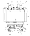
図2乃至図4は、本発明の一実施形態に係るライドアトラクションのライドの一例を示す図である。具体的には、図2は、本発明の一実施形態に係るライドアトラクションのライドの一例を示す正面図であり、図3は、該ライドの一例を示す部分断面側面図であり、図4は、該ライドの一例を示す平面図である。 2 to 4 are diagrams showing an example of rides of ride attractions according to an embodiment of the present invention. Specifically, FIG. 2 is a front view showing an example of a ride of a ride attraction according to an embodiment of the present invention, FIG. 3 is a partial cross-sectional side view showing an example of the ride, and FIG. FIG. 3 is a plan view showing an example of the ride.
これらの図を参照して、ライド20は、台車21と該台車21に載置され連結された車体22とを含む。台車21は、各車軸211に回転自在に軸支された主車輪212及びガイド車輪213を含み、主車輪212及びガイド車輪213が軌道11の一対のレールを四方から狭持する(図3参照)。これによって、ライド20は、ツイストや宙返り等といった動きをしても、軌道11から脱線することなく、安全に走行することができる。図示はされていないが、台車21は、軌道11上を走行時の振動を軽減するためのサスペンションを含んでも良い。また、台車21は、軌道11に設けられた制動機構111と相まってライド20の移動速度を制御する、制動機構214を含む。
With reference to these drawings, the
車体22は、乗客を載置するための空間を形成しており、車体22前部は左右に膨らみを有している(図4参照)。車体22の外観形状は、特に限定されるものではなく、例えば、ライドアトラクションのテーマに従った形状(例えば、宇宙をテーマにした仮想現実空間であれば、スペースクラフトを模擬した形状)で構成される。
The
車体22内には、乗客が着座するための複数の座席23が設けられている。座席23は、例えば基台24に固着されている。本例では、車体22内に前後2つずつの座席23a及び23bが設けられ、4人乗りのライド20を構成している。図3から明らかなように、後部座席23bは、その座面が前部座席23aの座面より高い位置に形成されるように配置され、また、図4から明らかなように、前部座席23aは、前方の1点に向かうように、前後方向の仮想軸線から僅かに斜めに配置されている。かかる配置により、2つの前部座席23aの間の空間が確保され、後部座席23bに着座した乗客は、前方の視界を遮られることがない。特に、本例では、コース10内に設けられたゲーム区間Gにおいて、スクリーン上にゲーム映像が表示されるが、後部座席23bに着座した乗客にも、ゲームをするに十分なスクリーン映像が提供されることになる。
In the
各座席23には、安全装置25が設けられている。安全装置25は、着座した乗客の身体に当接し、その動きを抑止するための抑止部材251を含み、抑止部材251は、支持部252の軸252aに回動自在に枢設されている。安全装置25はまた、抑止部材251に連結された駆動機構253を含む。駆動機構253は、図示しない制御装置の制御の下、支持部252の軸252aを中心に抑止部材251を回転させる装置である。駆動機構53は、例えば、油圧ダンパーを含み、油圧ダンパーの伸縮動作を利用して、抑止部材251を回転させる。駆動機構253は、典型的には、抑止部材251が正しい位置にあることを検出するためのセンサを含み(図示せず)、抑止部材251が正しい位置にあることが検出されると、駆動機構253は、抑止部材251が意図せず回動しないようにロックされる。なお、後述するように、本実施形態の安全装置25は、座席23に着座した乗客によって操作される入力装置27を備える。
Each
図3に良く示されるように、ライド20は、通信ユニット26を備え、外部の装置(例えばゲーム制御装置130)と通信可能に構成されている。典型的には、ライド20の通信ユニット26は、少なくとも送信機能を有する送信部を含むが、これに限られるものでなく、双方向通信を可能にするため、他の送信部から送信された信号を受信する受信部を含んでいても良い。本例では、通信ユニット26は、車体22前部に設けられている。また、通信ユニット26の送信部から出力された信号を受信する受信部は、例えば、スクリーン110に設けられる。送信部と受信部との間の通信には、例えば、赤外線通信が用いられるが、これに限られるものではない。本例では、通信ユニット26は後述する入力装置27から出力される操作信号を送信し、スクリーン110に設けられた受信部1111はこれを受け、ゲーム制御装置130に送る。
As well shown in FIG. 3, the
また、ライド20は、ライドアトラクションの演出に用いられる例えば照明器やそれに必要な電力を供給するバッテリ等を含んでも良い。また、ライド20は、例えば、車体22の前部及び/又は後部に設けられた緩衝装置(バンパー)を含んでも良い。
In addition, the
図5は、本発明の一実施形態に係るライドの安全装置の一例を示す斜視図である。上述したように、安全装置25は、抑止部材251と、支持部252とを含む。図中、駆動機構253は省略されている。
FIG. 5 is a perspective view showing an example of a ride safety device according to an embodiment of the present invention. As described above, the
同図に示すように、支持部252は、例えば、座席23を固着した基台24に取り付けられ、座席23のヘッドレストの後方を横断方向に延伸するように配置されている。支持部252の両端部は、抑止部材251を枢設するための軸252aを構成する。
As shown in the figure, the
抑止部材251は、支持部252の軸252aに回動自在に枢設された部材であり、その外層は、例えば、衝撃を吸収可能な弾性体で覆われ、乗客の身体を保護する。抑止部材251は、乗客が座席23に着座(着席)し及び座席23から起立(離席)することができる空間が確保される開放位置と、該座席23に着座した乗客の身体の動きを抑止する抑止位置との間を支持部252の軸252aを中心に揺動可能に構成されている。本例では、抑止部材251が座席23のヘッドレスト上方に移動した位置を開放位置とし、抑止部材251が座席23の背もたれに対向する位置を抑止位置としている。安全装置25の構造は、典型的には、軌道11に沿って走行するライド20の動きの度合いに応じて決定される。例えば、安全装置25は、座席23の前方に設けられた抑止部材251が乗客の身体の動きを抑止するように構成されても良い。
The restraining
抑止部材251は、例えば、支持部252の両端部から延伸する左右一対のアーム部分2511を含み、一対のアーム部分2511は、その先端部分で結合するように構成されている。従って、抑止部材251が抑止位置にあるとき、乗客は、肩から上の部分を、一対のアーム部分2511によって形成される開口から突出させることができる。このとき、抑止部材251の裏面(第2面)が着座した乗客の両肩から腹部にかけた部分に対向するように構成され、抑止部材251の該先端部分は乗客の腹部近傍に位置することになる。
The restraining
抑止部材251には、把持部2512が設けられても良い。本例では、乗客が肘を曲げたときに把持できるように、一対のアーム部分2511のそれぞれの部分に把持部2512が設けられている。把持部2512は、ライド20の走行中、座席23に着座した乗客によって必要に応じて把持される。
The restraining
典型的には、抑止部材251の表面(第1面)には、乗客が操作可能な入力装置27が設けられる。本例では、一対のアーム部分2511が結合する先端部分に、入力装置27が設けられている。入力装置27は例えばガンを模した形状をしているが、これに限られるものでない。入力装置27は、乗客の操作に基づく操作信号を、例えば、一対のアーム部分2511の少なくとも一方の内部に設けられた配線(ハーネス)を介して、外部の機器に出力する。本例では、入力装置27から出力された操作信号は、通信ユニット26を介して、ゲーム制御装置130に送られる。上述したように、通信ユニット26は、送信部と受信部とから構成され、例えば、赤外線通信により操作信号を伝送する。
Typically, an
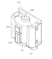
図6乃至9は、本発明の一実施形態に係るライドの入力装置27の一例を示す図である。具体的には、図6は、本発明の一実施形態に係るライドの入力装置27の一例を示す斜視図であり、図7及び図8は、該入力装置27の部分の一例を示す分解斜視図である。また、図9は、本発明の一実施形態に係るライドの入力装置27の部分の一例を示す分解平面図である。
6 to 9 are diagrams showing an example of a
入力装置27は、本体部271と、操作部2721を有する可動部272と、ヘッド部273とを含んで構成される。本実施形態の入力装置27は、乗客の手の大きさに合わせて、適度な大きさで形成される。本体部271は、その背面に設けられた固定プレート2711を含み、入力装置27は、固定プレート2711が安全装置25の抑止部材251の台座(図示せず)に螺子等の締結部材で固着されることで、安全装置25と一体的に構成される。本体部271は、例えば、硬質性樹脂材料で作成されるが、これに限られるものでない。本体部271は、その内部の空間に可動部272を収容し、可動部272を横断方向に回動可能なように枢設する。本体部271内部の下方には、ストッパー2712が設けられ(図8には明示されていない。)、回動する可動部272の背面部分にストッパー2712が当接することにより、可動部272の回動範囲を規定する。本体部271前面には開口部が形成されており、可動部272の操作部2721は開口部から表出している。
The
本体部271はまた、回転角度センサ2713を含む。回転角度センサ2713は、例えば、ロータリエンコーダであり、可動部272の軸272aの回転角度に応じて信号を出力する。回転角度センサ2713は、例えば0.4度の回転角度を検出する分解能を有するが、これに限定されるものでない。回転角度センサ2713は、適宜、既知のものを選択することができる。
The
可動部272は、鉛直方向に延伸する軸272aを有し、軸272aを中心にして所定の範囲内で回動するように構成されている。可動部272の回動範囲は、本体部271内部下方に設けられたストッパー2712によって規定される。回動範囲の一例としては、例えば、ニュートラル位置から約左右±30度である。可動部272の軸272aの回転角度は、本体部271に設けられた回転角度センサ2713から出力される信号に基づいて算出される。可動部272もまた、例えば、硬質性樹脂材料で作成されるが、これに限られるものでない。
The
可動部272はまた、本体部271の開口部から表出するように構成された操作部2721を含む。操作部2721は、例えば、乗客の手の指によって操作されるスイッチ2722を含む。スイッチ2722は、例えば、市販の押しボタン型スイッチを用いることができる。操作部2721はまた、可動部272を横断方向に回動させる乗客の手の指を受けるように形成された突起部2723を有しても良い。従って、乗客は、突起部2723を押圧操作することによって、容易に、可動部272を横断方向に回動させることができるようになる。突起部2723は、例えば、スイッチ2722の下方に配置されるが、これに限られるものでない。
The
ヘッド部273は、本体部271の上部に設けられている。本例では、入力装置27の外観がガンの形状を模すように、前記本体部271よりも前方に延出するように設けられている。ただし、ヘッド部273は、乗客が強く把持することで破損しないよう、前方へ延出する長さを抑えている。ヘッド部273は、例えば、これらの図示はされていないが、入力装置27における処理を司る処理回路1000やスピーカ2732を収容する(また、図10参照)。処理回路1000は、例えば、回転角度センサ2713から出力される信号を増幅したり、スイッチ2722の操作に応じて効果音信号を生成し、スピーカ2732に出力する。ヘッド部273には、例えば、スピーカ2732から再生される効果音が入力装置27外部に伝わるように音抜けスリット2731が設けられる。また、ヘッド部273の上部には、弾性材料で形成された保護部材2733が設けられている。保護部材2733は、ライド20の激しい動きによって乗客の頭部が大きく振られ、万が一、乗客の頭部が入力装置27に接触しても、衝撃を緩衝する役目を果たす。なお、本例では、本体部271とヘッド部273を別体で構成したが、これに限るものでなく、本例でヘッド部273に収容された各種の構成要素を本体部271に収容するように構成しても良い。
The
なお、本実施形態の入力装置27は、可動部272が左右方向のみに回動するように構成されているが、これに限られるものではなく、例えば、上下方向にも回動して、上下左右方向への操作を指示できるように構成されても良い。
Note that the
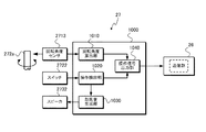
図10は、本発明の一実施形態に係るライドの入力装置の機能構成の一例を示すブロック図である。本実施形態の入力装置27の機能構成は、処理回路1000の制御の下で、実現される。処理回路1000は、例えば、回転角度算出部1010と、操作検出部1020と、効果音生成部1030と、操作信号出力部1040とを含んで構成される。
FIG. 10 is a block diagram illustrating an example of a functional configuration of a ride input device according to an embodiment of the present invention. The functional configuration of the
回転角度算出部1010は、回転角度センサ2713から送られる可動部272の軸271aの回転角度(回転量)に応じた信号を受け付けて、可動部272が操作された回転角度を算出する。回転角度算出部1010は、例えば、軸271aのニュートラル位置を基準に、回転角度センサ2713から送られるエンコード信号をカウントすることによって、可動部272の回転角度を算出する。回転角度算出部1010は、算出した回転角度に基づく操作信号を操作信号出力部1040に出力する。
The rotation
操作検出部1020は、その回路中にスイッチ2722を含むように構成され、スイッチ2722が操作されると、これを検出し、操作信号を効果音生成部1030及び操作信号出力部1040に出力する。操作検出部1020は、スイッチ2722が操作されると、その操作された時間に拘わらず、1つのパルス状の操作信号を出すように構成されても良いし、操作された時間に応じてONレベルの長さを有する操作信号を出力するようにしても良い。或いは、操作された時間に応じて複数のパルス状の操作信号が出力されても良い。
The
効果音生成部1030は、操作検出部1020から送られる操作信号に基づいて、スピーカ2732から再生される効果音に対応するオーディオ信号を生成する。例えば、ライドアトラクションにおいて提供されるゲームがシューティングゲームであれば、ガンの発射音に対応するオーディオ信号を生成する。効果音生成部1030は、生成したオーディオ信号をスピーカ2732に出力し、スピーカ2732は、送られるオーディオ信号に従って効果音を再生する。
The sound
操作信号出力部1040は、回転角度算出部1010及び/又は操作検出部1020から送られる操作信号を、通信ユニット26に適する形式に変換した後、これを通信ユニット26に出力する。通信ユニット26は、操作信号出力部1040から受け付けた操作信号を、送信部を用いて送信する。
The operation
図11は、本発明の一実施形態に係るライドアトラクションにおいて提供されるゲームを実現するための概略システム構成の一例を示す図である。 FIG. 11 is a diagram illustrating an example of a schematic system configuration for realizing a game provided in a ride attraction according to an embodiment of the present invention.
本実施形態のライドアトラクションでは、コース10の一部に設けられたゲーム区間Gにおいてライド20の乗客にゲームが提供される(図1参照)。ゲーム区間Gには、ライド20の乗客に正対するように、ゲーム映像を表示するためのスクリーン110が設けられる。本実施形態では、ゲーム区間Gに設けられた移動スクリーン機構100によって、軌道11上を走行するライド20と正対しながら、ライド20の進行方向と同一方向にスクリーン110が移動するように構成される。
In the ride attraction of the present embodiment, a game is provided to passengers of the
移動スクリーン機構100は、例えば、軌道11に沿って設けられた別の軌道上を走行する移動ユニット120を含む。スクリーン110は、移動ユニット120に取り付けられ、ライド20の進行方向と同一方向に移動する移動ユニット120に搬送されて、ライド20と所定の間隔を保ちながら移動する。移動ユニット120はまた、ゲーム制御装置130やプロジェクタ140を搭載する。
The moving
ゲーム制御装置130は、ライドアトラクションにおいてライド20の乗客に提供するゲームの実行を統括的に制御する。即ち、ゲーム制御装置130は、プロセッサを含んで構成され(図示せず)、プロセッサの制御の下、ゲームプログラムに従ってゲームの実行を制御して、ゲーム映像を生成し、これに基づく映像信号をプロジェクタ140に出力する。ゲーム制御装置130は、例えば、ライド20がゲーム区間Gにおける軌道11上のゲーム開始位置に来たことを通知されると、ゲームの実行を開始する。より具体的には、軌道11に沿ってライド20の位置を検出するセンサが設けられ、ゲーム制御装置130は、該センサからの検出信号を受け取ることで、ゲームの実行を開始する。
The
上述したように、ライド20は、安全装置25に取り付けられた入力装置27と、入力装置27から送られる操作信号を送信する通信ユニット(送信部)26を含む。通信ユニット26から送信された操作信号は、スクリーン110の前面に設けられた受信部1111によって受信され、ゲーム制御装置130に送られる。これにより、ライド20の乗客は、スクリーン110に表示されたゲーム映像に対して、入力装置27を操作して、ゲームを楽しむことができる。
As described above, the
ゲーム制御装置130は、ゲームの実行を終了すると、そのゲーム結果を、例えば、図示しないゲーム管理装置に送る。ゲーム管理装置は、ゲーム区間G内でゲーム制御装置130により実行されたゲームの結果(例えば、獲得ポイント)を収集し、ランキングを決定するため集計する。ゲームの結果は、例えば、ライド20毎又はライド20の乗客毎に収集され、ランキング集計される。
When the
ゲーム制御装置130が提供するゲームの内容は、適宜、ライドアトラクションのテーマに従って選択される。例えば、本実施形態のゲームは、ライド20に乗った複数の乗客が協力し合って、敵を攻撃するシューティングゲームであるとする。図12は、本実施形態に係るライドアトラクションにおけるスクリーン上に表示されたゲーム映像の一例を示す図である。同図に示すように、スクリーン110上のゲーム映像による画面1211(ゲーム画面)には、ゲーム制御装置130によって挙動が制御される敵キャラクタ1212と、入力装置27を介して乗客によって操作される照準1213とが表示されている。図中、4つの照準1213はそれぞれ、各乗客が操作する照準に対応する。また、入力装置27の可動部272の回動動作に応じて、各照準1213は左右方向にのみ移動する。従って、ゲーム画面1211全体を移動する敵キャラクタ1212に対応するため、前部座席23aの乗客は、ゲーム画面1211の下半分の領域を移動する照準1213の操作を受け持ち、前部座席23aよりも高い位置にある後部座席23bの乗客は、ゲーム画面1211の上半分の領域を移動する照準1213の操作を受け持つように、ゲームプログラムは構成される。
The content of the game provided by the
ゲーム中は、乗客は、スクリーン110に表示されるゲーム映像中の敵キャラクタ1212に照準1213が合うように、入力装置27の可動部272を左右に動かし、照準1213が合ったタイミングでスイッチ2722を押下する。ゲーム制御装置130は、ゲーム映像の表示タイミングと、入力装置27からの操作信号及びそのタイミングに基づいて、敵キャラクタ1212に弾が命中したか否かを判断する。ゲーム制御装置130は、敵キャラクタ1212に弾が命中したと判断する場合、例えば、獲得ポイントを加算する。
During the game, the passenger moves the
このように、本実施形態では、入力装置27の可動部272の可動範囲に対応して、照準1213の移動範囲が制限されている。従って、ゲームにおいては、座席23の位置に応じてゲーム画面1211内の受け持ち範囲を定め、その範囲で照準1213が移動するようになっている。これにより、入力装置27による照準1213の移動操作が単純であるにも拘わらず、複数の乗客が協力しながら、ゲーム画面1211全体に亘って展開する敵キャラクタ1212に攻撃を与えるという状況を作り出すことができ、ゲームの興趣性を高めることができる。
Thus, in this embodiment, the movement range of the
本明細書に開示された方法に関して、該方法においてなされる処理乃至動作は、該方法を実行した結果に矛盾が生じない限り、異なる順番で実行されうる。また、処理乃至動作は単に例示されたものであり、いくつかの処理乃至動作は、任意的なものであって、省略することができ、また、それぞれを結合したり、追加の処理乃至動作によって拡充することもできる。例えば、処理乃至動作の順序を入れ替え、または、処理乃至動作を並列的に実行することは、本発明の要旨に含まれる。 With respect to the methods disclosed herein, the processes or operations performed in the methods can be performed in a different order as long as the results of executing the methods do not conflict. In addition, the processes or operations are merely examples, and some processes or operations are optional and may be omitted, or may be combined with each other or by additional processes or operations. It can also be expanded. For example, changing the order of processes or operations or executing the processes or operations in parallel is included in the gist of the present invention.
本発明は、乗客を乗せたライド(車両)が、コースを構成する軌道に沿って移動するライドアトラクションに広く適用することができる。 The present invention can be widely applied to ride attractions in which a ride (vehicle) carrying passengers moves along a track constituting a course.
10…コース
11…軌道
100…移動スクリーン機構
20…ライド
21…台車
211…車軸
212…主車輪
213…ガイド車輪
214…制動機構
22…車体
23…座席
24…基台
25…安全装置
251…抑止部材
252…支持部
253…駆動機構
26…通信ユニット
27…入力装置
271…本体部
2711…固定プレート
2712…ストッパー
2713…回転角度センサ
272…可動部
2721…操作部
2712…スイッチ
2713…突出部
273…ヘッド部
2731…スリット
DESCRIPTION OF
Claims (1)
前記抑止部材を前記第1位置と前記第2位置との間を回動自在に軸支する前記座席の後方に配置された支持部と、 A support portion disposed behind the seat for pivotally supporting the restraining member between the first position and the second position;
前記抑止部材に設けた前記支持部から延伸する一対のアーム部分を含み、該一対のアーム部分は、前記第2位置において前記乗客の腹部近傍に対応する部分で結合される先端部分と、 Including a pair of arm portions extending from the support portion provided on the restraining member, the pair of arm portions being joined at a portion corresponding to the vicinity of the abdomen of the passenger at the second position;
から構成される前記乗客の身体の動きを抑制する安全装置と、 A safety device for suppressing movement of the passenger's body, comprising:
前記乗客に正対するように設けられたゲーム映像を表示する表示手段と、 Display means for displaying a game image provided to face the passenger;
前記先端部分の表面に設けられた、前記座席に着座した前記乗客が前記表示手段に表示された前記ゲーム映像に対して操作可能な入力装置と、 An input device that is provided on a surface of the tip portion and is operable with respect to the game image displayed on the display means by the passenger seated on the seat;
少なくとも前記ゲーム映像を生成するゲーム制御手段と、 Game control means for generating at least the game video;
を備え、 With
前記入力装置は、 The input device is:
前記乗客の手の大きさにあわせて握ることが可能に構成された、可動しない本体部と、 A non-movable main body configured to be able to be gripped according to the size of the passenger's hand;
前記乗客の指によって操作可能に構成された、可動する操作部と、 A movable operation unit configured to be operable by the passenger's finger;
を有し、 Have
前記入力装置は、前記乗客の前記操作部の操作に基づく操作信号を出力し、前記ゲーム制御手段に送り、 The input device outputs an operation signal based on the operation of the operation unit of the passenger, and sends the operation signal to the game control means.
前記ゲーム制御手段は、前記表示手段に前記ゲーム制御手段により挙動が制御されるキャラクタ映像と、照準を表示し、 The game control means displays on the display means a character image whose behavior is controlled by the game control means and an aim,
前記ゲーム映像のタイミングと、前記入力装置からの前記操作信号及びそのタイミングに基づいて前記キャラクタ映像と前記照準が一致したかを判定する、 Determining whether the character video and the aim coincide with each other based on the timing of the game video, the operation signal from the input device, and the timing;
ことを特徴とするアトラクション装置。 The attraction apparatus characterized by the above-mentioned.
Priority Applications (3)
| Application Number | Priority Date | Filing Date | Title |
|---|---|---|---|
| JP2012136365A JP6030348B2 (en) | 2012-06-15 | 2012-06-15 | Attraction device |
| PCT/JP2013/064888 WO2013187235A1 (en) | 2012-06-15 | 2013-05-29 | Ride vehicle in amusement ride and safety device used for same as well as input device for ride vehicle |
| CN201380029090.0A CN104507545B (en) | 2012-06-15 | 2013-05-29 | Ride apparatus in riding type recreational facilities and its safety device and the input unit of ride apparatus that use |
Applications Claiming Priority (1)
| Application Number | Priority Date | Filing Date | Title |
|---|---|---|---|
| JP2012136365A JP6030348B2 (en) | 2012-06-15 | 2012-06-15 | Attraction device |
Publications (3)
| Publication Number | Publication Date |
|---|---|
| JP2014000170A JP2014000170A (en) | 2014-01-09 |
| JP2014000170A5 JP2014000170A5 (en) | 2015-05-14 |
| JP6030348B2 true JP6030348B2 (en) | 2016-11-24 |
Family
ID=49758065
Family Applications (1)
| Application Number | Title | Priority Date | Filing Date |
|---|---|---|---|
| JP2012136365A Active JP6030348B2 (en) | 2012-06-15 | 2012-06-15 | Attraction device |
Country Status (3)
| Country | Link |
|---|---|
| JP (1) | JP6030348B2 (en) |
| CN (1) | CN104507545B (en) |
| WO (1) | WO2013187235A1 (en) |
Cited By (1)
| Publication number | Priority date | Publication date | Assignee | Title |
|---|---|---|---|---|
| KR20200006596A (en) * | 2017-05-25 | 2020-01-20 | 유니버셜 시티 스튜디오스 엘엘씨 | System for Vehicle Vehicle Restraint |
Families Citing this family (22)
| Publication number | Priority date | Publication date | Assignee | Title |
|---|---|---|---|---|
| US9943759B2 (en) * | 2014-06-16 | 2018-04-17 | Universal City Studios Llc | Interactive game floor system and method |
| CN106139594B (en) * | 2015-04-02 | 2018-09-28 | 江苏金刚文化科技集团股份有限公司 | Seat system |
| CN106139598A (en) * | 2015-04-02 | 2016-11-23 | 江苏金刚文化科技集团股份有限公司 | Novel pressure shoulder device |
| CN106139597B (en) * | 2015-04-02 | 2018-09-28 | 江苏金刚文化科技集团股份有限公司 | Seat retaining mechanism for amusement facility |
| CN105169704B (en) * | 2015-09-28 | 2017-11-10 | 万达文化旅游规划研究院有限公司 | Sectional track live shell interaction gun post and its application method |
| US9751022B1 (en) | 2015-10-28 | 2017-09-05 | Eric Fram | Amusement park ride with adjustable thrill levels |
| US9486135B1 (en) | 2015-10-28 | 2016-11-08 | Eric Fram | Amusement park ride with adjustable thrill level |
| KR20170106161A (en) * | 2016-03-11 | 2017-09-20 | 주식회사 상화 | Virtual reality experience apparatus |
| WO2018100800A1 (en) | 2016-11-29 | 2018-06-07 | ソニー株式会社 | Information processing device, information processing method, and computer program |
| US11040731B2 (en) * | 2017-04-29 | 2021-06-22 | Universal Studios LLC | Passenger restraint with integrated lighting |
| DE102017121730A1 (en) * | 2017-09-19 | 2019-03-21 | Mack Rides Gmbh & Co Kg | Passenger recording for a ride, method for operating such a passenger reception and ride with such a passenger reception |
| US10821934B2 (en) | 2017-10-24 | 2020-11-03 | Universal City Studios Llc | Passenger restraint with integrated audio system |
| DE102017126488B3 (en) * | 2017-11-10 | 2019-02-07 | Mack Rides Gmbh & Co. Kg | Ironing secondary fuse |
| US20190184935A1 (en) * | 2017-12-19 | 2019-06-20 | Universal City Studios, LLC | Passive restraint techniques for amusement park rides |
| US10838216B2 (en) | 2018-01-19 | 2020-11-17 | Universal City Studios Llc | Virtual reality/augmented reality rapid deployment system |
| CN108543314A (en) * | 2018-06-20 | 2018-09-18 | 中山市金马科技娱乐设备股份有限公司 | A kind of strut device of novel amusement facility |
| SI3594169T1 (en) | 2018-07-13 | 2021-08-31 | Epsilon Kran Gmbh | Vehicle with a crane and a crane control |
| US11224819B2 (en) * | 2019-01-07 | 2022-01-18 | Universal City Studios Llc | Systems and methods for maneuvering a vehicle |
| CN110465077A (en) * | 2019-06-11 | 2019-11-19 | 江苏博人文化科技有限公司 | Virtual reality multiple degrees of freedom amusement experience system |
| US10828576B1 (en) * | 2019-07-29 | 2020-11-10 | Universal City Studios Llc | Motion exaggerating virtual reality ride systems and methods |
| DE202019106723U1 (en) * | 2019-12-03 | 2021-03-04 | Raw Tex International Establishment | Passenger Carrier and Roller Coaster |
| JP7297151B2 (en) * | 2020-07-03 | 2023-06-23 | 深▲せん▼怡豊自動化科技有限公司 | AGV recreational transport tool and connection assembly |
Family Cites Families (11)
| Publication number | Priority date | Publication date | Assignee | Title |
|---|---|---|---|---|
| JP2778215B2 (en) * | 1990-06-27 | 1998-07-23 | 株式会社島津製作所 | Orbital play equipment |
| JP3428151B2 (en) * | 1994-07-08 | 2003-07-22 | 株式会社セガ | Game device using image display device |
| JPH08112454A (en) * | 1994-10-18 | 1996-05-07 | Masago Kogyo Kk | Jet coaster |
| JPH1176626A (en) * | 1997-09-08 | 1999-03-23 | Masago Kogyo Kk | Jumping tower |
| US6220965B1 (en) * | 1998-07-08 | 2001-04-24 | Universal City Studios Inc. | Amusement system |
| JP2000344194A (en) * | 1999-06-03 | 2000-12-12 | Takenaka Komuten Co Ltd | Aerial floating device |
| JP4507299B2 (en) * | 1999-07-16 | 2010-07-21 | 株式会社セガ | Amusement vehicles and vehicle amusement facilities |
| GB2363737B (en) * | 1999-10-11 | 2004-03-10 | Vladimir A Gnezdilov | Amusement ride |
| JP2001129262A (en) * | 1999-11-04 | 2001-05-15 | Namco Ltd | Game device using game vehicle |
| US8021236B2 (en) * | 2009-03-30 | 2011-09-20 | Blammo, Llc | Amusement ride system and method |
| CN102151407A (en) * | 2011-01-27 | 2011-08-17 | 深圳市远望落星山科技有限公司 | Interactive railcar |
-
2012
- 2012-06-15 JP JP2012136365A patent/JP6030348B2/en active Active
-
2013
- 2013-05-29 CN CN201380029090.0A patent/CN104507545B/en active Active
- 2013-05-29 WO PCT/JP2013/064888 patent/WO2013187235A1/en active Application Filing
Cited By (2)
| Publication number | Priority date | Publication date | Assignee | Title |
|---|---|---|---|---|
| KR20200006596A (en) * | 2017-05-25 | 2020-01-20 | 유니버셜 시티 스튜디오스 엘엘씨 | System for Vehicle Vehicle Restraint |
| KR102165031B1 (en) * | 2017-05-25 | 2020-10-13 | 유니버셜 시티 스튜디오스 엘엘씨 | Vehicle restraint system |
Also Published As
| Publication number | Publication date |
|---|---|
| CN104507545A (en) | 2015-04-08 |
| WO2013187235A1 (en) | 2013-12-19 |
| JP2014000170A (en) | 2014-01-09 |
| CN104507545B (en) | 2017-07-07 |
Similar Documents
| Publication | Publication Date | Title |
|---|---|---|
| JP6030348B2 (en) | Attraction device | |
| AU2010100998B4 (en) | Inflatable vehicles for simulating driving for use with video games | |
| US6347999B1 (en) | Pinball simulator game system | |
| KR101194699B1 (en) | Curve track simulation devices | |
| US8025581B2 (en) | Interactive interface mounting assembly for amusement and theme park rides | |
| JP6957218B2 (en) | Simulation system and program | |
| US20120270663A1 (en) | Inflatable Vehicles for Simulating Driving for use with Handheld Video Games | |
| WO2014147752A1 (en) | Self-propelled skateboard | |
| KR101350181B1 (en) | Bobsleigh simulator and method for controlling process | |
| JP6393482B2 (en) | Game device | |
| JP5464312B2 (en) | Amusement vehicle system and control method thereof | |
| US5967897A (en) | Game input device and game apparatus | |
| WO2018086709A1 (en) | Trackless amusement ride | |
| CN104307178A (en) | Amusement cockpit with three-dimensional image simulation | |
| TWI621468B (en) | A somatosensory device of simulated steering | |
| CN108854056B (en) | Body sensing device for simulating steering | |
| JP5348376B2 (en) | Amusement vehicle system | |
| GB2359261A (en) | Simulator with spherical cabinet | |
| JP2007117772A (en) | Game system and information storing medium | |
| JP2010082341A (en) | Program, information storage medium, and game console | |
| JP2001087552A (en) | Game device | |
| JP3239711U (en) | human crane game device | |
| CN206087087U (en) | Children scooter | |
| TWI620161B (en) | A somatosensory device that strengthens turn to skidding | |
| JP2014033804A (en) | Operation device and game device |
Legal Events
| Date | Code | Title | Description |
|---|---|---|---|
| A521 | Request for written amendment filed |
Free format text: JAPANESE INTERMEDIATE CODE: A523 Effective date: 20150330 |
|
| A621 | Written request for application examination |
Free format text: JAPANESE INTERMEDIATE CODE: A621 Effective date: 20150330 |
|
| A711 | Notification of change in applicant |
Free format text: JAPANESE INTERMEDIATE CODE: A711 Effective date: 20151211 |
|
| A131 | Notification of reasons for refusal |
Free format text: JAPANESE INTERMEDIATE CODE: A131 Effective date: 20160614 |
|
| A521 | Request for written amendment filed |
Free format text: JAPANESE INTERMEDIATE CODE: A523 Effective date: 20160812 |
|
| RD03 | Notification of appointment of power of attorney |
Free format text: JAPANESE INTERMEDIATE CODE: A7423 Effective date: 20160812 |
|
| A521 | Request for written amendment filed |
Free format text: JAPANESE INTERMEDIATE CODE: A821 Effective date: 20160812 |
|
| TRDD | Decision of grant or rejection written | ||
| A01 | Written decision to grant a patent or to grant a registration (utility model) |
Free format text: JAPANESE INTERMEDIATE CODE: A01 Effective date: 20160921 |
|
| A61 | First payment of annual fees (during grant procedure) |
Free format text: JAPANESE INTERMEDIATE CODE: A61 Effective date: 20161020 |
|
| R150 | Certificate of patent or registration of utility model |
Ref document number: 6030348 Country of ref document: JP Free format text: JAPANESE INTERMEDIATE CODE: R150 |
|
| R250 | Receipt of annual fees |
Free format text: JAPANESE INTERMEDIATE CODE: R250 |
|
| R250 | Receipt of annual fees |
Free format text: JAPANESE INTERMEDIATE CODE: R250 |
|
| R250 | Receipt of annual fees |
Free format text: JAPANESE INTERMEDIATE CODE: R250 |
|
| R250 | Receipt of annual fees |
Free format text: JAPANESE INTERMEDIATE CODE: R250 |
|
| R250 | Receipt of annual fees |
Free format text: JAPANESE INTERMEDIATE CODE: R250 |