JP6020479B2 - Cold rolling equipment and cold rolling method - Google Patents
Cold rolling equipment and cold rolling method Download PDFInfo
- Publication number
- JP6020479B2 JP6020479B2 JP2014014646A JP2014014646A JP6020479B2 JP 6020479 B2 JP6020479 B2 JP 6020479B2 JP 2014014646 A JP2014014646 A JP 2014014646A JP 2014014646 A JP2014014646 A JP 2014014646A JP 6020479 B2 JP6020479 B2 JP 6020479B2
- Authority
- JP
- Japan
- Prior art keywords
- meandering
- steel strip
- steel
- cold rolling
- heating
- Prior art date
- Legal status (The legal status is an assumption and is not a legal conclusion. Google has not performed a legal analysis and makes no representation as to the accuracy of the status listed.)
- Active
Links
- 238000005097 cold rolling Methods 0.000 title claims description 135
- 238000000034 method Methods 0.000 title claims description 30
- 229910000831 Steel Inorganic materials 0.000 claims description 455
- 239000010959 steel Substances 0.000 claims description 455
- 238000010438 heat treatment Methods 0.000 claims description 194
- 238000005096 rolling process Methods 0.000 claims description 158
- 239000000463 material Substances 0.000 claims description 48
- 238000011144 upstream manufacturing Methods 0.000 claims description 45
- 230000006698 induction Effects 0.000 claims description 18
- 238000005259 measurement Methods 0.000 claims description 3
- 238000003466 welding Methods 0.000 description 26
- 238000004364 calculation method Methods 0.000 description 10
- 230000008859 change Effects 0.000 description 10
- 230000002159 abnormal effect Effects 0.000 description 9
- 238000009826 distribution Methods 0.000 description 9
- 230000000052 comparative effect Effects 0.000 description 8
- 229910000976 Electrical steel Inorganic materials 0.000 description 7
- 230000004907 flux Effects 0.000 description 7
- 238000010586 diagram Methods 0.000 description 6
- 230000007704 transition Effects 0.000 description 6
- 230000009471 action Effects 0.000 description 5
- 230000009467 reduction Effects 0.000 description 5
- 238000005304 joining Methods 0.000 description 4
- XUIMIQQOPSSXEZ-UHFFFAOYSA-N Silicon Chemical compound [Si] XUIMIQQOPSSXEZ-UHFFFAOYSA-N 0.000 description 3
- 230000007423 decrease Effects 0.000 description 3
- 230000007246 mechanism Effects 0.000 description 3
- 230000002093 peripheral effect Effects 0.000 description 3
- 229910052710 silicon Inorganic materials 0.000 description 3
- 239000010703 silicon Substances 0.000 description 3
- 229910000677 High-carbon steel Inorganic materials 0.000 description 2
- 208000009205 Tinnitus Diseases 0.000 description 2
- 238000005452 bending Methods 0.000 description 2
- 238000005098 hot rolling Methods 0.000 description 2
- 238000004519 manufacturing process Methods 0.000 description 2
- 238000005554 pickling Methods 0.000 description 2
- 230000008569 process Effects 0.000 description 2
- 239000010935 stainless steel Substances 0.000 description 2
- 229910001220 stainless steel Inorganic materials 0.000 description 2
- 239000002436 steel type Substances 0.000 description 2
- 238000004804 winding Methods 0.000 description 2
- 210000001015 abdomen Anatomy 0.000 description 1
- 238000009825 accumulation Methods 0.000 description 1
- 239000010953 base metal Substances 0.000 description 1
- 239000010960 cold rolled steel Substances 0.000 description 1
- 239000000470 constituent Substances 0.000 description 1
- 230000007547 defect Effects 0.000 description 1
- 238000007599 discharging Methods 0.000 description 1
- 238000005516 engineering process Methods 0.000 description 1
- 238000009434 installation Methods 0.000 description 1
- 238000000926 separation method Methods 0.000 description 1
- 230000035882 stress Effects 0.000 description 1
- 230000001629 suppression Effects 0.000 description 1
- 230000002195 synergetic effect Effects 0.000 description 1
- 230000008646 thermal stress Effects 0.000 description 1
Images


Classifications
-
- B—PERFORMING OPERATIONS; TRANSPORTING
- B21—MECHANICAL METAL-WORKING WITHOUT ESSENTIALLY REMOVING MATERIAL; PUNCHING METAL
- B21B—ROLLING OF METAL
- B21B37/00—Control devices or methods specially adapted for metal-rolling mills or the work produced thereby
- B21B37/68—Camber or steering control for strip, sheets or plates, e.g. preventing meandering
-
- B—PERFORMING OPERATIONS; TRANSPORTING
- B21—MECHANICAL METAL-WORKING WITHOUT ESSENTIALLY REMOVING MATERIAL; PUNCHING METAL
- B21C—MANUFACTURE OF METAL SHEETS, WIRE, RODS, TUBES OR PROFILES, OTHERWISE THAN BY ROLLING; AUXILIARY OPERATIONS USED IN CONNECTION WITH METAL-WORKING WITHOUT ESSENTIALLY REMOVING MATERIAL
- B21C51/00—Measuring, gauging, indicating, counting, or marking devices specially adapted for use in the production or manipulation of material in accordance with subclasses B21B - B21F
-
- B—PERFORMING OPERATIONS; TRANSPORTING
- B21—MECHANICAL METAL-WORKING WITHOUT ESSENTIALLY REMOVING MATERIAL; PUNCHING METAL
- B21B—ROLLING OF METAL
- B21B2271/00—Mill stand parameters
- B21B2271/02—Roll gap, screw-down position, draft position
-
- B—PERFORMING OPERATIONS; TRANSPORTING
- B21—MECHANICAL METAL-WORKING WITHOUT ESSENTIALLY REMOVING MATERIAL; PUNCHING METAL
- B21B—ROLLING OF METAL
- B21B2273/00—Path parameters
- B21B2273/04—Lateral deviation, meandering, camber of product
-
- B—PERFORMING OPERATIONS; TRANSPORTING
- B21—MECHANICAL METAL-WORKING WITHOUT ESSENTIALLY REMOVING MATERIAL; PUNCHING METAL
- B21B—ROLLING OF METAL
- B21B37/00—Control devices or methods specially adapted for metal-rolling mills or the work produced thereby
- B21B37/58—Roll-force control; Roll-gap control
-
- B—PERFORMING OPERATIONS; TRANSPORTING
- B21—MECHANICAL METAL-WORKING WITHOUT ESSENTIALLY REMOVING MATERIAL; PUNCHING METAL
- B21B—ROLLING OF METAL
- B21B37/00—Control devices or methods specially adapted for metal-rolling mills or the work produced thereby
- B21B37/74—Temperature control, e.g. by cooling or heating the rolls or the product
-
- B—PERFORMING OPERATIONS; TRANSPORTING
- B21—MECHANICAL METAL-WORKING WITHOUT ESSENTIALLY REMOVING MATERIAL; PUNCHING METAL
- B21B—ROLLING OF METAL
- B21B38/00—Methods or devices for measuring, detecting or monitoring specially adapted for metal-rolling mills, e.g. position detection, inspection of the product
- B21B38/02—Methods or devices for measuring, detecting or monitoring specially adapted for metal-rolling mills, e.g. position detection, inspection of the product for measuring flatness or profile of strips
-
- B—PERFORMING OPERATIONS; TRANSPORTING
- B21—MECHANICAL METAL-WORKING WITHOUT ESSENTIALLY REMOVING MATERIAL; PUNCHING METAL
- B21B—ROLLING OF METAL
- B21B38/00—Methods or devices for measuring, detecting or monitoring specially adapted for metal-rolling mills, e.g. position detection, inspection of the product
- B21B38/04—Methods or devices for measuring, detecting or monitoring specially adapted for metal-rolling mills, e.g. position detection, inspection of the product for measuring thickness, width, diameter or other transverse dimensions of the product
-
- B—PERFORMING OPERATIONS; TRANSPORTING
- B21—MECHANICAL METAL-WORKING WITHOUT ESSENTIALLY REMOVING MATERIAL; PUNCHING METAL
- B21B—ROLLING OF METAL
- B21B39/00—Arrangements for moving, supporting, or positioning work, or controlling its movement, combined with or arranged in, or specially adapted for use in connection with, metal-rolling mills
- B21B39/02—Feeding or supporting work; Braking or tensioning arrangements, e.g. threading arrangements
- B21B39/08—Braking or tensioning arrangements
- B21B39/082—Bridle devices
-
- B—PERFORMING OPERATIONS; TRANSPORTING
- B21—MECHANICAL METAL-WORKING WITHOUT ESSENTIALLY REMOVING MATERIAL; PUNCHING METAL
- B21B—ROLLING OF METAL
- B21B45/00—Devices for surface or other treatment of work, specially combined with or arranged in, or specially adapted for use in connection with, metal-rolling mills
- B21B45/004—Heating the product
Landscapes
- Engineering & Computer Science (AREA)
- Mechanical Engineering (AREA)
- Metal Rolling (AREA)
- Control Of Metal Rolling (AREA)
Description
本発明は、鋼板を冷間圧延する冷間圧延設備および冷間圧延方法に関するものである。 The present invention relates to a cold rolling facility and a cold rolling method for cold rolling a steel sheet.
従来、鋼板の冷間圧延の操業においては、完全連続式冷間タンデムミル、酸洗ライン後段の連続式タンデムミル、単スタンドのリバースミル等、冷間圧延設備の如何を問わず、室温程度、すなわち高くとも40℃程度の鋼板が冷間圧延される。これは、鋼板の温度増加に伴って鋼板の変形抵抗が低下することを考慮しても、被圧延材である鋼板の温度を高めることによって得られるメリットに比べ、被るデメリットが大きいからである。例えば、鋼板の温度を高めることによるメリットとして、鋼板の変形抵抗の低下に伴う圧延動力の低下が挙げられるが、このメリットは、鋼板の冷間圧延の操業において、殆ど無視される程度である。これに対して、鋼板を昇温するためのコスト的損失が非常に大きいこと、高温の鋼板のハンドリングが労働環境面から問題であること等、鋼板の高温化に起因するデメリットが多大である。 Conventionally, in the cold rolling operation of steel sheets, regardless of the cold rolling equipment, such as fully continuous cold tandem mill, continuous tandem mill after the pickling line, single stand reverse mill, etc., about room temperature, That is, a steel plate at about 40 ° C. at the highest is cold-rolled. This is because, even if it is considered that the deformation resistance of the steel sheet decreases as the temperature of the steel sheet increases, the disadvantages to be incurred are larger than the merit obtained by increasing the temperature of the steel sheet as the material to be rolled. For example, as a merit by increasing the temperature of the steel sheet, there is a reduction in rolling power accompanying a decrease in the deformation resistance of the steel sheet, but this merit is almost negligible in the cold rolling operation of the steel sheet. On the other hand, the demerit resulting from the high temperature of a steel plate, such as the cost loss for heating up a steel plate being very large, and the handling of a high temperature steel plate from a working environment side, are great.
上述したような室温レベルの鋼板が冷間圧延に供された場合、冷間圧延中の鋼板の幅方向端部(以下、エッジ部という)に耳割れが生じる可能性がある。特に、1%以上の珪素を含有する珪素鋼板、ステンレス鋼板、高炭素鋼板等の難圧延材は一般の鋼板と比較して脆性材料となるため、室温レベルの難圧延材を冷間圧延した際、耳割れが顕著に発生する。耳割れの程度が大きい場合には、耳割れを起点として鋼板が冷間圧延中に破断する虞がある。 When a steel sheet at the room temperature level as described above is subjected to cold rolling, there is a possibility that an ear crack may occur at the end portion in the width direction (hereinafter referred to as an edge portion) of the steel plate during cold rolling. In particular, since hard-rolled materials such as silicon steel plates, stainless steel plates, and high-carbon steel plates containing 1% or more of silicon become brittle materials compared to general steel plates, when cold-rolling hard-rolled materials at room temperature level , Ear cracks occur remarkably. When the degree of ear cracking is large, the steel sheet may break during cold rolling starting from the ear cracking.
この問題を解決する方法として、例えば、特許文献1には、珪素鋼板を冷間圧延するに際して、エッジ部を60℃(延性−脆性遷移温度)以上の温度に昇温した珪素鋼板を被圧延材として圧延機に供給する珪素鋼板の冷間圧延方法が開示されている。また、特許文献2には、鋼板のエッジ部を誘導加熱で昇温させる手段として、C型インダクタ(誘導子)を用いた一対の誘導加熱装置が開示されている。この特許文献2に記載の誘導加熱装置は、鋼板の幅方向(以下、板幅方向と適宜いう)の両エッジ部をC型インダクタのスリット内に上下から非接触に挟み、C型インダクタのコイルに電源装置から高周波電流を流して鋼板の厚さ方向(以下、板厚方向と適宜いう)の磁束を鋼板の両エッジ部に与えて、これら両エッジ部に誘導電流を生じさせ、この誘導電流によって発生するジュール熱により、これら両エッジ部を加熱する。 As a method for solving this problem, for example, in Patent Document 1, when cold rolling a silicon steel plate, a silicon steel plate whose edge is heated to a temperature of 60 ° C. (ductility-brittle transition temperature) or higher is a material to be rolled. A cold rolling method of a silicon steel sheet supplied to a rolling mill is disclosed. Patent Document 2 discloses a pair of induction heating devices using C-type inductors (inductors) as means for raising the temperature of an edge portion of a steel plate by induction heating. In this induction heating apparatus described in Patent Document 2, both edge portions in the width direction of a steel plate (hereinafter referred to as “plate width direction”) are sandwiched in a slit of a C-type inductor from above and below in a non-contact manner. A high-frequency current is supplied from the power supply device to give a magnetic flux in the thickness direction of the steel sheet (hereinafter referred to as the “thickness direction”) to both edge portions of the steel plate to generate induced currents at both edge portions. Both of these edge portions are heated by Joule heat generated by.
ここで、鋼板のエッジ部を所定の温度に昇温するためには、鋼板のエッジ部とこのエッジ部を板厚方向の上下から非接触に挟むC型インダクタとの重なり合う長さ(以下、ラップ長という)が予め設定された値となるように、C型インダクタを支持する台車の位置を鋼板の板幅に応じてセットする必要がある。しかしながら、実操業においては、鋼板のセンタリング不良や平坦度不良によって鋼板が板幅方向に蛇行するため、ラップ長が変化してしまう。ラップ長が小さくなれば、磁束の流れを遮る渦電流の発生が少なくなるため、力率が悪化して無効電流が増加し、C型インダクタのコイルに流れる高周波電流が定格値まで増加しても所定の出力が出せず、この結果、エッジ部の加熱不足が生じることがある。あるいは、エッジ部の一部分を過度に加熱する事態(局部異常加熱)に至ることがある。 Here, in order to raise the temperature of the edge portion of the steel plate to a predetermined temperature, the overlapping length of the edge portion of the steel plate and the C-type inductor sandwiching the edge portion from the top and bottom in the thickness direction (hereinafter referred to as lap) It is necessary to set the position of the carriage that supports the C-type inductor according to the plate width of the steel plate so that the length) is a preset value. However, in actual operation, since the steel plate meanders in the plate width direction due to a poor centering or flatness of the steel plate, the wrap length changes. If the wrap length is reduced, the generation of eddy currents that block the flow of magnetic flux is reduced. Therefore, the power factor deteriorates, the reactive current increases, and the high-frequency current flowing through the coil of the C-type inductor increases to the rated value. A predetermined output cannot be obtained, and as a result, insufficient heating of the edge portion may occur. Or the situation (local abnormal heating) which heats a part of edge part excessively may be reached.
加熱不足の場合には、鋼板の冷間圧延中にエッジ部に耳割れが生じてしまう。この耳割れは、上述したように、冷間圧延中の鋼板の破断を引き起こす原因になる。一方、局部異常加熱の場合には、鋼板のエッジ部に、熱応力による変形に起因して耳波が生じてしまう。耳波の程度が大きい場合には、冷間圧延中の鋼板に絞り破断が生じる虞があり、このため、鋼板の安定した冷間圧延が困難になる。以上のことから、冷間圧延される鋼板のエッジ部を誘導加熱によって所定の温度に昇温するに際しては、ラップ長を最適な値に制御することが極めて重要となる。 In the case of insufficient heating, an edge crack occurs at the edge during cold rolling of the steel sheet. As described above, the ear cracks cause breakage of the steel sheet during cold rolling. On the other hand, in the case of local abnormal heating, an ear wave is generated at the edge portion of the steel sheet due to deformation due to thermal stress. When the degree of the ear wave is large, there is a possibility that drawing breakage occurs in the steel sheet during cold rolling, which makes it difficult to stably cold-roll the steel sheet. From the above, it is extremely important to control the lap length to an optimum value when the temperature of the edge portion of the cold-rolled steel plate is raised to a predetermined temperature by induction heating.
なお、上述したラップ長の制御に関する従来技術として、例えば、搬送される鋼板のエッジ部を加熱する加熱コイルと、この加熱コイルを搭載したコイル台車体と、このコイル台車体を鋼板の進行方向と直角の方向へ移動させる移動機構と、このコイル台車体に取り付けられて鋼板のエッジ部に接触するガイドローラとを備えた誘導加熱装置がある(特許文献3参照)。この特許文献3に記載の誘導加熱装置は、鋼板の誘導加熱中にガイドローラが鋼板のエッジ部に接触するように移動機構を動作させて、鋼板と加熱コイルとの相対位置関係を常に一定に保つようにしている。
In addition, as a prior art regarding the control of the lap length described above, for example, a heating coil for heating an edge portion of a steel plate to be conveyed, a coil base body mounted with the heating coil, and the coil base body as a traveling direction of the steel plate There is an induction heating device that includes a moving mechanism that moves in a right-angle direction and a guide roller that is attached to the coil base body and contacts an edge portion of a steel plate (see Patent Document 3). In the induction heating device described in
また、鋼板の左右エッジ部が通過するラインの左右側位置に鋼板進行方向と直角方向に進退する台車を配置し、これら左右の各台車に、鋼板のエッジ部を上下から挟むインダクタを設置し、台車の自動位置コントローラにより、鋼板のエッジ部とインダクタとのラップ長を制御して、鋼板のエッジ部を加熱する誘導加熱制御方法がある(特許文献4参照)。この特許文献4に記載の誘導加熱制御方法では、左右の各インダクタの加熱コイルに流れる高周波電流を検出して、鋼板の蛇行によるラップ長の変化によって発生する電流値の偏差を求め、予め記憶した偏差電流値と偏差電流値を零とするに必要なインダクタの台車位置補正量との関係に基づき台車位置補正値を求める。ついで、電流値の大きい側の台車位置初期設定値から台車位置補正値を減算すると共に、電流値の小さい側の台車位置初期設定値に台車位置補正値を加算して左右の台車補正位置を求める。その後、左右の各台車の自動位置コントローラに、前述のように加減算した左右の台車補正位置を出力し、これにより、これら左右の各台車の位置を自動位置コントローラが補正するようにし、これを通して、鋼板の左右エッジ部と左右の各インダクタとのラップ長を制御している。 In addition, a cart that moves back and forth in the direction perpendicular to the steel plate traveling direction is arranged at the left and right side positions of the line through which the left and right edge portions of the steel plate pass, and an inductor that sandwiches the edge portion of the steel plate from above and below is installed on each of these left and right carts, There is an induction heating control method in which the edge portion of a steel sheet is heated by controlling the wrap length between the edge portion of the steel sheet and the inductor by an automatic position controller of the carriage (see Patent Document 4). In the induction heating control method described in Patent Document 4, a high-frequency current flowing in the heating coils of the left and right inductors is detected, and a deviation of a current value generated by a change in lap length due to meandering of the steel sheet is obtained and stored in advance. A carriage position correction value is obtained based on the relationship between the deviation current value and the carriage position correction amount of the inductor necessary to make the deviation current value zero. Next, the cart position correction value is subtracted from the cart position initial setting value on the larger current value side, and the cart position correction value is added to the cart position initial setting value on the smaller current value side to obtain the left and right cart correction positions. . Then, the left and right cart correction positions added and subtracted as described above are output to the automatic position controllers of the left and right carts, thereby allowing the automatic position controller to correct the positions of the left and right carts, The wrap length between the left and right edge portions of the steel sheet and the left and right inductors is controlled.
上述した従来技術において、鋼板のエッジ部と誘導加熱装置のインダクタとのラップ長は、鋼板の蛇行に起因するエッジ部の位置変化に応じて補正される。言うなれば、このエッジの位置変化に応じてラップ長を補正するフィードバック制御が、従来、行われている。しかしながら、インダクタを搭載する台車の移動速度と比較して鋼板の蛇行速度が速い故に、上述した従来技術では、鋼板の蛇行に起因するエッジ部の位置変化にラップ長のフィードバック制御を十分に追従させることが困難である。このため、冷間圧延される前の鋼板のエッジ部を誘導加熱によって所定の温度に昇温するに際して、ラップ長を最適な値に安定して制御することは極めて困難である。この結果、被圧延材としての鋼板においてエッジ部の加熱不足または局部異常加熱が発生し、この状態の鋼板を冷間圧延した際、エッジ部の加熱不足による耳割れに起因して鋼板の破断が発生し、あるいは、エッジ部の局部異常加熱による耳波に起因して鋼板の絞り破断が発生してしまう。このような鋼板の耳割れに起因する破断または絞り破断(以下、これらを纏めて鋼板破断と適宜いう)の発生は、鋼板の冷間圧延の操業を阻害するとともに、冷間圧延の生産効率の低下を招来する。 In the prior art described above, the wrap length between the edge portion of the steel plate and the inductor of the induction heating device is corrected according to the position change of the edge portion caused by the meandering of the steel plate. In other words, feedback control for correcting the wrap length in accordance with the edge position change has been conventionally performed. However, since the meandering speed of the steel plate is higher than the moving speed of the carriage on which the inductor is mounted, the above-described conventional technology sufficiently follows the feedback control of the lap length to the position change of the edge portion caused by the meandering of the steel plate. Is difficult. For this reason, it is extremely difficult to stably control the lap length to an optimum value when the temperature of the edge portion of the steel sheet before cold rolling is increased to a predetermined temperature by induction heating. As a result, in the steel sheet as the material to be rolled, insufficient heating or localized abnormal heating of the edge portion occurs, and when the steel sheet in this state is cold-rolled, the steel sheet breaks due to ear cracks due to insufficient heating of the edge portion. The steel plate is squeezed or fractured due to the ear wave due to the local abnormal heating of the edge portion. The occurrence of breakage or drawing breakage (hereinafter collectively referred to as steel plate breakage) due to such ear cracks in the steel sheet hinders the cold rolling operation of the steel sheet and reduces the production efficiency of the cold rolling. Incurs a decline.
本発明は、上記の事情に鑑みてなされたものであって、鋼板破断の発生を可能な限り抑制して、鋼板の安定した冷間圧延を実現することが可能な冷間圧延設備および冷間圧延方法を提供することを目的とする。 The present invention has been made in view of the above circumstances, and it is possible to suppress the occurrence of steel sheet breakage as much as possible, and to realize a cold rolling facility and a cold which can realize stable cold rolling of a steel sheet An object is to provide a rolling method.
上述した課題を解決し、目的を達成するために、本発明にかかる冷間圧延設備は、順次搬送される鋼板を加熱装置によって加熱し、加熱後の前記鋼板を、前記鋼板の搬送方向に並ぶ複数の圧延機を有するタンデム圧延機によって順次冷間圧延する冷間圧延設備において、前記加熱装置による加熱前の前記鋼板の蛇行量を測定する蛇行量測定部と、加熱前の前記鋼板の蛇行を修正する蛇行修正装置と、前記タンデム圧延機における最上流の圧延機による冷間圧延後の前記鋼板の形状を測定する形状測定部と、前記最上流の圧延機による冷間圧延後の前記鋼板の形状を制御する形状制御部と、前記蛇行量測定部による前記鋼板の蛇行量の測定値に基づき前記蛇行修正装置の動作を制御して、加熱前の前記鋼板の蛇行を制御し、且つ、前記形状測定部による前記鋼板の形状の測定値に基づき前記形状制御部の動作を制御して、前記タンデム圧延機による前記鋼板の冷間圧延に起因する前記鋼板の蛇行を制御する制御部と、を備えたことを特徴とする。 In order to solve the above-described problems and achieve the object, the cold rolling facility according to the present invention heats steel plates that are sequentially conveyed by a heating device, and arranges the heated steel plates in the conveying direction of the steel plates. In a cold rolling facility that sequentially performs cold rolling by a tandem rolling mill having a plurality of rolling mills, a meandering amount measuring unit that measures a meandering amount of the steel plate before heating by the heating device, and a meandering of the steel plate before heating A meander correcting device for correcting, a shape measuring unit for measuring the shape of the steel sheet after cold rolling by the most upstream rolling mill in the tandem rolling mill, and the steel sheet after cold rolling by the most upstream rolling mill A shape control unit for controlling the shape, and controlling the operation of the meandering correction device based on the measured value of the meandering amount of the steel plate by the meandering amount measuring unit, controlling the meandering of the steel plate before heating, and Shape measurement A control unit for controlling the operation of the shape control unit based on the measured value of the shape of the steel plate according to the above, and for controlling meandering of the steel plate due to cold rolling of the steel plate by the tandem rolling mill. It is characterized by.
また、本発明にかかる冷間圧延設備は、上記の発明において、前記蛇行修正装置は、前記加熱装置よりも前記鋼板の搬送方向の上流側に配置され、前記蛇行量測定部は、前記蛇行修正装置と前記加熱装置との間に配置されることを特徴とする。 Further, in the cold rolling facility according to the present invention, in the above invention, the meandering correction device is disposed upstream of the heating device in the conveying direction of the steel sheet, and the meandering amount measuring unit is the meandering correction. It arrange | positions between an apparatus and the said heating apparatus, It is characterized by the above-mentioned.
また、本発明にかかる冷間圧延設備は、上記の発明において、前記加熱装置は、前記鋼板の幅方向の両エッジ部を前記鋼板の厚さ方向の両側から非接触に挟むC型のインダクタを備え、誘導加熱方式によって前記鋼板のうちの前記両エッジ部を加熱することを特徴とする。 Further, in the cold rolling facility according to the present invention, in the above invention, the heating device includes a C-type inductor that sandwiches both edge portions in the width direction of the steel plate in a non-contact manner from both sides in the thickness direction of the steel plate. And the both edge portions of the steel plate are heated by an induction heating method.
また、本発明にかかる冷間圧延方法は、順次搬送される鋼板を加熱装置によって加熱し、加熱後の前記鋼板を、前記鋼板の搬送方向に並ぶ複数の圧延機を有するタンデム圧延機によって順次冷間圧延する冷間圧延方法において、前記加熱装置による加熱前の前記鋼板の蛇行量と、前記タンデム圧延機における最上流の圧延機による冷間圧延後の前記鋼板の形状とを測定する測定ステップと、前記鋼板の蛇行量の測定値に基づいて加熱前の前記鋼板の蛇行を制御し、且つ、前記鋼板の形状の測定値に基づいて前記鋼板の冷間圧延に起因する蛇行を制御する蛇行制御ステップと、を含むことを特徴とする。 In the cold rolling method according to the present invention, the steel plates sequentially conveyed are heated by a heating device, and the heated steel plates are sequentially cooled by a tandem rolling mill having a plurality of rolling mills arranged in the conveying direction of the steel plates. In the cold rolling method for hot rolling, a measuring step for measuring the meandering amount of the steel sheet before heating by the heating device and the shape of the steel sheet after cold rolling by the most upstream rolling mill in the tandem rolling mill; Meander control for controlling meandering of the steel sheet before heating based on the measured value of the meandering amount of the steel sheet, and controlling meandering due to cold rolling of the steel sheet based on the measured value of the shape of the steel sheet And a step.
また、本発明にかかる冷間圧延方法は、上記の発明において、前記測定ステップは、前記加熱装置よりも前記鋼板の搬送方向の上流側に配置されて加熱前の前記鋼板の蛇行を修正する蛇行修正装置と前記加熱装置との間に配置された蛇行量測定部によって、加熱前の前記鋼板の蛇行量を測定することを特徴とする。 Further, in the cold rolling method according to the present invention, in the above invention, the measuring step is arranged to be upstream of the heating device in the conveying direction of the steel plate and corrects the meander of the steel plate before heating. The meandering amount of the steel plate before heating is measured by a meandering amount measuring unit disposed between the correction device and the heating device.
また、本発明にかかる冷間圧延方法は、上記の発明において、前記鋼板の幅方向の両エッジ部を前記鋼板の厚さ方向の両側から非接触に挟むC型のインダクタを備えた前記加熱装置を用い、前記蛇行制御ステップによって蛇行を制御された前記鋼板の幅方向の両エッジ部を誘導加熱方式によって加熱する加熱ステップを含むことを特徴とする。 Further, in the cold rolling method according to the present invention, in the above invention, the heating apparatus including a C-type inductor that sandwiches both edge portions in the width direction of the steel sheet from both sides in the thickness direction of the steel sheet in a non-contact manner. And a heating step of heating both edge portions in the width direction of the steel sheet whose meandering is controlled by the meandering control step by an induction heating method.
本発明によれば、鋼板破断の発生を可能な限り抑制して、鋼板の安定した冷間圧延を実現することができるという効果を奏する。 According to the present invention, it is possible to suppress the occurrence of steel sheet breakage as much as possible and to realize stable cold rolling of the steel sheet.
以下に、添付図面を参照して、本発明にかかる冷間圧延設備および冷間圧延方法の好適な実施の形態について詳細に説明する。なお、本実施の形態により、本発明が限定されるものではない。 Exemplary embodiments of a cold rolling facility and a cold rolling method according to the present invention will be described below in detail with reference to the accompanying drawings. Note that the present invention is not limited to the embodiment.
(冷間圧延設備)
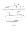
まず、本発明の実施の形態にかかる冷間圧延設備について説明する。図1は、本発明の実施の形態にかかる冷間圧延設備の一構成例を示す図である。図1に示すように、本実施の形態にかかる冷間圧延設備1は、被圧延材の搬送経路の入口端に巻戻し機2を備え、出口端にテンションリール12を備える。また、冷間圧延設備1は、巻戻し機2とテンションリール12との間に、被圧延材の搬送経路に沿って、溶接機3と、ルーパ4と、蛇行修正装置5と、板幅計6と、加熱装置7と、タンデム圧延機8および形状測定部10と、走間シャー11とを備える。このタンデム圧延機8における最上流の圧延機8aには、形状制御アクチュエータ9が設けられている。また、冷間圧延設備1は、蛇行修正装置5および形状制御アクチュエータ9を制御する制御部13を備える。
(Cold rolling equipment)
First, a cold rolling facility according to an embodiment of the present invention will be described. FIG. 1 is a diagram illustrating a configuration example of a cold rolling facility according to an embodiment of the present invention. As shown in FIG. 1, a cold rolling facility 1 according to the present embodiment includes a rewinder 2 at an entrance end of a conveyance path for a material to be rolled, and a
巻戻し機2は、熱延鋼板等の鋼材を巻いたコイルから鋼板15を巻き戻し、冷間圧延設備1における被圧延材の搬送経路へ鋼板15を順次払い出す。巻戻し機2から払い出された鋼板15は、ピンチロール等を経て、巻戻し機2よりも鋼板15の搬送方向の下流側に位置する溶接機3へ順次搬送される。
The unwinding machine 2 unwinds the steel plate 15 from a coil wound with a steel material such as a hot-rolled steel plate, and sequentially delivers the steel plate 15 to the transport path of the material to be rolled in the cold rolling facility 1. The steel plate 15 paid out from the unwinding machine 2 is sequentially conveyed to the
溶接機3は、レーザ溶接機等を用いて実現され、図1に示すように、巻戻し機2とルーパ4との間における被圧延材の搬送経路近傍に配置される。溶接機3は、巻戻し機2から払い出された複数の鋼板15を順次受け入れ、これら複数の鋼板15のうちの搬送方向に先行する鋼板(以下、先行材という)の尾端部と、この先行材に後続する鋼板(以下、後行材という)の先端部とを溶接する。溶接機3は、巻戻し機2からの複数の鋼板15に対して、上述した先行材の尾端部と後行材の先端部との溶接処理を順次行い、これにより、これら複数の鋼板15の先尾端部同士を接合してなる鋼帯16を形成する。鋼帯16は、溶接機3から搬出された後、溶接機3よりも鋼帯16の搬送方向の下流側に位置するルーパ4へ順次搬送される。
The
ルーパ4は、冷間圧延等の連続処理が施される鋼帯16を適宜蓄積または払い出すための装置である。具体的には、図1に示すように、ルーパ4は、複数の固定ロール4a,4c,4e,4gと、固定ロール4a,4c,4e,4gに対して接近または離間する方向(以下、接離方向という)に移動可能な複数の可動ロール4b,4d,4fとを備える。このようなルーパ4において、図1に示すように、固定ロール4a、可動ロール4b、固定ロール4c、可動ロール4d、固定ロール4e、可動ロール4f、および固定ロール4gは、この順に鋼帯16の搬送経路に沿って配置されている。
The looper 4 is an apparatus for appropriately accumulating or discharging the
固定ロール4a,4c,4e,4gは、各々、設置位置が固定された搬送ロールであり、例えば図1に示すように、溶接機3から蛇行修正装置5に向かう方向に並ぶように配置される。各固定ロール4a,4c,4e,4gは、鋼帯16を巻き掛けられる等によって鋼帯16に接触しながら、駆動部(図示せず)の作用によって自身のロール中心軸を中心に回転する。これにより、各固定ロール4a,4c,4e,4gは、鋼帯16をその搬送経路に沿って搬送するとともに、定位置において鋼帯16に張力を付与する。一方、可動ロール4b,4d,4fは、各々、ループカー等の移動機構(図示せず)の作用によって接離方向に移動可能な搬送ロールである。可動ロール4b,4d,4fは、鋼帯16を巻き掛けられる等によって鋼帯16に接触しながら、自身のロール中心軸を中心に回転する。これにより、可動ロール4b,4d,4fは、固定ロール4a,4c,4e,4gとの間において鋼帯16を張架するとともに、鋼帯16をその搬送方向に送出する。
Each of the fixed
上述したような構成を有するルーパ4は、図1に示すように、タンデム圧延機8よりも鋼帯16の搬送方向の上流側、詳細には溶接機3と蛇行修正装置5との間に配置され、鋼帯16を蓄積または払い出しする。これにより、ルーパ4内における鋼帯16の滞留時間が調整される。このルーパ4による鋼帯16の蓄積または払い出しは、溶接機3による鋼板溶接の際に生じる鋼帯16の搬送休止時間等を吸収するために行われる。
As shown in FIG. 1, the looper 4 having the above-described configuration is disposed upstream of the
例えば、冷間圧延設備1において、溶接機3が鋼帯16の溶接を行っていない期間、ルーパ4は、溶接機3から鋼帯16を受け入れつつ、可動ロール4b,4d,4fを固定ロール4a,4c,4e,4gから離間させる。これにより、ルーパ4は、溶接機3からの鋼帯16を蓄積しつつ、タンデム圧延機8側に向けて鋼帯16を連続的に搬送する。一方、溶接機3が各鋼板15の先尾端部同士を溶接している期間、溶接機3からルーパ4への鋼帯16の搬送が停止する。この場合、ルーパ4は、可動ロール4b,4d,4fを固定ロール4a,4c,4e,4gに接近させる。これにより、ルーパ4は、上述したように蓄積していた鋼帯16をタンデム圧延機8側に払い出して、溶接機3側からタンデム圧延機8側への鋼帯16の連続的な搬送を維持する。ルーパ4は、溶接機3による鋼帯16の溶接が完了後、再び、可動ロール4b,4d,4fを固定ロール4a,4c,4e,4gから離間させる。ルーパ4は、この状態において溶接機3から受け入れた鋼帯16を蓄積しつつ、タンデム圧延機8側へ鋼帯16を連続的に搬送する。このようにして、ルーパ4は、溶接機3側からタンデム圧延機8側への鋼帯16の連続的な搬送を維持する。このルーパ4から払い出された鋼帯16は、ルーパ4よりも鋼帯16の搬送方向の下流側に位置する蛇行修正装置5へ順次搬送される。
For example, in the cold rolling equipment 1, the looper 4 receives the
蛇行修正装置5は、図1に示すように、加熱装置7よりも鋼帯16の搬送方向の上流側に配置され、加熱装置7による加熱前の鋼帯16の蛇行を修正する。本実施の形態において、蛇行修正装置5は、4つのブライドルロール5a〜5dと、ブライドルロール5a〜5dを傾動するロール傾動部5eとを備える。
As shown in FIG. 1, the meandering correction device 5 is disposed upstream of the heating device 7 in the conveying direction of the
ブライドルロール5a〜5dは、鋼帯16を搬送するロール体としての機能と、鋼帯16の張力を制御するためのロール体としての機能とを有する。具体的には、ブライドルロール5a〜5dは、各々、鋼帯16の巻付き角が所定値以上(例えば90度以上)となるように、鋼帯16の搬送経路に沿って配置される。なお、巻付き角は、ブライドルロール5a〜5dのうちの鋼帯16が接触する外周面部分に対応するブライドルロール5a〜5dの中心角である。このように配置されたブライドルロール5a〜5dは、鋼帯16を巻き掛けられる等によって鋼帯16に接触しながら、駆動部(図示せず)の作用によって自身のロール中心軸を中心に回転する。これにより、ブライドルロール5a〜5dは、自身の外周面と鋼帯16との摩擦力によって鋼帯16に張力を付与しながら、ルーパ4側から加熱装置7側へ鋼帯16を搬送する。
The bridle rolls 5 a to 5 d have a function as a roll body for conveying the
詳細には、ブライドルロール5aは、ブライドルロール5bと協働して鋼帯16を張架するとともに、ルーパ4側からブライドルロール5b側へ鋼帯16を搬送する。ブライドルロール5bは、ブライドルロール5a,5cと協働して鋼帯16を張架するとともに、ブライドルロール5a側からブライドルロール5c側へ鋼帯16を搬送する。ブライドルロール5cは、ブライドルロール5b,5dと協働して鋼帯16を張架するとともに、ブライドルロール5b側からブライドルロール5d側へ鋼帯16を搬送する。ブライドルロール5dは、ブライドルロール5cと協働して鋼帯16を張架するとともに、ブライドルロール5c側から加熱装置7側へ鋼帯16を搬送する。上述したようにブライドルロール5a〜5dによって鋼帯16に付与された張力は、ブライドルロール5a〜5dの各回転速度を調整することにより、制御される。
Specifically, the
また、ブライドルロール5a〜5dは、鋼帯16の蛇行を矯正することが可能なステアリング機能を有する。具体的には、ブライドルロール5a〜5dは、自身のロール中心軸を回転中心として回転可能な状態でロール傾動部5eに支持される。ロール傾動部5eは、ブライドルロール5a〜5dのロール中心軸が水平方向に対して傾斜するように、ブライドルロール5a〜5dを傾動する。図2は、本実施の形態における蛇行修正装置のブライドルロールを傾動する状態を例示する図である。ロール傾動部5eは、鋼帯16に蛇行が生じた場合、例えば図2に示すように、鋼帯16を張架するブライドルロール5a,5bの各ロール中心軸C1,C2が水平方向に対して傾斜するようにブライドルロール5a,5bを傾動する。本実施の形態において、ロール傾動部5eは、ブライドルロール5c,5dについても、上記のブライドルロール5a,5bの場合と同様に傾動する。ブライドルロール5a〜5dは、このようなロール傾動部5eの傾動作用、すなわちステアリング機能によって、鋼帯16の蛇行方向と反対方向に下る傾斜を形成し、これにより、加熱装置7による加熱前の鋼帯16の蛇行を修正する。
Further, the bridle rolls 5a to 5d have a steering function capable of correcting the meandering of the
上述した蛇行修正装置5から搬出された鋼帯16は、蛇行修正装置5の出側に配置された板幅計6を経由し、蛇行修正装置5よりも鋼帯16の搬送方向の下流側に配置された加熱装置7へ順次搬送される。
The
板幅計6は、加熱装置7による加熱前の鋼帯16の蛇行量を測定する蛇行量測定部としての機能を有する装置であり、図1に示すように、蛇行修正装置5と加熱装置7との間に配置される。板幅計6は、蛇行修正装置5の出側において鋼帯16の両エッジ部を検出し、検出した両エッジ部の各位置を算出する。ついで、板幅計6は、算出した両エッジ部の各位置をもとに、鋼帯16の板幅方向の中心位置を算出し、この中心位置と鋼帯16の搬送経路中心との差を、鋼帯16の蛇行量として算出する。また、板幅計6は、得られた両エッジ部の各位置をもとに、鋼帯16の板幅を算出する。板幅計6は、このような蛇行修正装置5の出側における鋼帯16の蛇行量および板幅の算出を連続的または所定時間毎に断続的に実行する。その都度、板幅計6は、算出した鋼帯16の蛇行量を、蛇行修正装置5の出側における鋼帯16の蛇行量の測定値として制御部13に送信する。且つ、板幅計6は、算出した鋼帯16の板幅を、蛇行修正装置5の出側における鋼帯16の板幅の測定値として加熱装置7に送信する。
The board width meter 6 is a device having a function as a meandering amount measuring unit for measuring the meandering amount of the
加熱装置7は、順次搬送される鋼帯16を冷間圧延前に加熱するものである。本実施の形態において、加熱装置7は、図1に示すように、タンデム圧延機8よりも鋼帯16の搬送方向の上流側、詳細には板幅計6とタンデム圧延機8における最上流の圧延機8aとの間に配置され、誘導加熱方式によって鋼帯16のうちの両エッジ部を加熱(誘導加熱)する。図3は、本実施の形態における冷間圧延設備の加熱装置の一構成例を示す図である。図3に示すように、加熱装置7は、鋼帯16の板幅方向の両エッジ部16a,16bを鋼帯16の板厚方向の両側(例えば上下)から非接触に挟む一対のC型のインダクタ71a,71bを備える。
The heating device 7 heats the
インダクタ71aの脚部72a,73aには、加熱コイル74aが設けられる。加熱コイル74aは、インダクタ71aの脚部72a,73aの間隙内を鋼帯16のエッジ部16aが通過する際、このエッジ部16aに板厚方向の磁束を与えて、このエッジ部16aを誘導加熱する。一方、インダクタ71bの脚部72b,73bには、加熱コイル74bが設けられる。加熱コイル74bは、インダクタ71bの脚部72b,73bの間隙内を鋼帯16のエッジ部16bが通過する際、このエッジ部16bに板厚方向の磁束を与えて、このエッジ部16bを誘導加熱する。
A
また、加熱装置7は、図3に示すように、整合盤77と、高周波電源78と、計算ユニット79とを備える。高周波電源78は、整合盤77を介して加熱コイル74a,74bに接続される。また、高周波電源78には、計算ユニット79が接続される。計算ユニット79は、鋼帯16の板厚、搬送速度および鋼種に基づいて鋼帯16の加熱条件を設定し、設定した加熱条件に応じて、加熱コイル74a,74bに流す高周波電流の出力を高周波電源78に指示する。高周波電源78は、この計算ユニット79からの出力指示に基づき、整合盤77を介して加熱コイル74a,74bに高周波電流を流し、これにより、加熱コイル74a,74bに板厚方向の磁束(高周波磁束)を生じさせる。この高周波磁束によって、鋼帯16の両エッジ部16a,16bに誘導電流が生じ、誘導電流によって両エッジ部16a,16bにジュール熱が発生する。両エッジ部16a,16bは、発生したジュール熱によって誘導加熱され、この結果、延性−脆性遷移温度以上の温度に昇温する。
Moreover, the heating apparatus 7 is provided with the matching
一方、加熱装置7は、図3に示すように、インダクタ71a,71bを各々鋼帯16の板幅方向に移動させる台車75a,75bと、インダクタ71a,71bの位置を制御する位置制御部76a,76bとを備える。インダクタ71aは台車75a上に設置され、インダクタ71bは台車75b上に設置されている。台車75a,75bは、鋼帯16の板幅方向に移動することによって、インダクタ71a,71bを鋼帯16の板幅方向に各々移動させる。位置制御部76a,76bには、図3に示すように、計算ユニット79が接続される。計算ユニット79は、上述した板幅計6から鋼帯16の板幅の測定値を受信し、受信した板幅の測定値に応じて、鋼帯16の板幅方向におけるインダクタ71a,71bの各目標位置(詳細には加熱コイル74a,74bの各目標位置)を算出する。計算ユニット79は、算出したインダクタ71a,71bの各目標位置を位置制御部76a,76bに各々送信する。位置制御部76a,76bは、計算ユニット79から受信したインダクタ71a,71bの各目標位置に基づいて、台車75a,75bを駆動制御し、台車75a,75bの駆動制御を通して、インダクタ71a,71bの位置を制御する。
On the other hand, as shown in FIG. 3, the heating device 7 includes
詳細には、位置制御部76aは、インダクタ71aの位置と鋼帯16の板幅に応じた目標位置とが一致するように、鋼帯16の板幅方向における台車75aの移動を制御し、この台車75aの制御を通して、インダクタ71aの位置を目標位置に制御する。これと同時に、位置制御部76bは、インダクタ71bの位置と鋼帯16の板幅に応じた目標位置とが一致するように、鋼帯16の板幅方向における台車75bの移動を制御し、この台車75bの制御を通して、インダクタ71bの位置を目標位置に制御する。この結果、鋼帯16の両エッジ部16a,16bとインダクタ71a,71bとの各ラップ長La,Lb(図3参照)は、鋼帯16の板幅の変化によらず定常に制御される。このように定常に制御されたラップ長La,Lbは、鋼帯16の両エッジ部16a,16bを延性−脆性遷移温度以上の温度に昇温するに最適な値となっている。
Specifically, the
本実施の形態において、図3に示すように、鋼帯16のエッジ部16aとインダクタ71aとのラップ長Laは、インダクタ71aの脚部72a,73aによって板厚方向の上下から非接触に挟まれるエッジ部16aとインダクタ71a(詳細には脚部72a,73a)との重なり合う長さである。鋼帯16のエッジ部16bとインダクタ71bとのラップ長Lbは、インダクタ71bの脚部72b,73bによって板厚方向の上下から非接触に挟まれるエッジ部16bとインダクタ71b(詳細には脚部72b,73b)との重なり合う長さである。
In the present embodiment, as shown in FIG. 3, the wrap length La between the
タンデム圧延機8は、順次搬送される鋼帯16を連続的に冷間圧延するタンデム型の圧延機であり、鋼帯16の搬送方向に並ぶ複数の圧延機(本実施の形態においては4つの圧延機8a〜8d)を有する。タンデム圧延機8は、図1に示すように、加熱装置7よりも鋼帯16の搬送方向の下流側、詳細には加熱装置7と走間シャー11との間に配置され、加熱装置7による加熱後の鋼帯16を順次冷間圧延する。
The
タンデム圧延機8を構成する4つの圧延機8a〜8dは、この順で鋼帯16の搬送方向に並設される。すなわち、タンデム圧延機8において、圧延機8aは、鋼帯16の搬送方向の最上流に位置し、圧延機8dは、鋼帯16の搬送方向の最下流に位置する。この最上流の圧延機8aの後段(鋼帯16の搬送方向の下流側)には、圧延機8bが配置される。この圧延機8bと最下流の圧延機8dとの間には、圧延機8cが配置される。加熱装置7による加熱後の鋼帯16は、加熱装置7の出側からタンデム圧延機8の入側(最上流の圧延機8a)に向かって搬送される。タンデム圧延機8は、この加熱後の鋼帯16を最上流の圧延機8aによって受け入れ、ついで、この受け入れた鋼帯16を圧延機8a〜8dによって連続的に冷間圧延する。これにより、タンデム圧延機8は、この鋼帯16の板厚を所定の目標板厚にする。タンデム圧延機8による冷間圧延後の鋼帯16は、最下流の圧延機8dの出側に搬出され、その後、ピンチロール等を経て走間シャー11へ順次搬送される。
The four
また、タンデム圧延機8における最上流の圧延機8aには、形状制御アクチュエータ9が設けられる。形状制御アクチュエータ9は、タンデム圧延機8における最上流の圧延機8aによる冷間圧延後の鋼帯16の形状を制御する形状制御部としての機能を有する。形状制御アクチュエータ9は、バックアップロール等を介して最上流の圧延機8aのワークロール8aaに撓みまたは傾斜を付与し、これにより、最上流の圧延機8aによる冷間圧延後の鋼帯16の形状を制御する。このような鋼帯16の形状制御を通して、形状制御アクチュエータ9は、例えば、この冷間圧延後の鋼帯16の板幅方向に非対称な形状を対称な形状に修正する。また、形状制御アクチュエータ9は、最上流の圧延機8aによる冷間圧延後の鋼帯16の形状を制御することにより、タンデム圧延機8による鋼帯16の冷間圧延に起因する鋼帯16の蛇行を修正する。
Further, the most
形状測定部10は、タンデム圧延機8における最上流の圧延機8aによる冷間圧延後の鋼帯16の形状を測定する。具体的には、形状測定部10は、鋼帯16の応力を板幅方向の所定領域毎に検出する複数のセンサが外周面に設けられたロール体等を用いて構成され、図1に示すように、最上流の圧延機8aの出側(圧延機8a,8b間)に配置される。形状測定部10は、自身のロール中心軸を中心に1回転する都度、最上流の圧延機8aの出側における鋼帯16の板幅方向の張力分布を測定し、得られた張力分布をもとに、最上流の圧延機8aの出側における鋼帯16の形状(以下、鋼帯形状と適宜いう)を測定する。形状測定部10は、このように鋼帯形状を測定する都度、得られた鋼帯形状の測定値を制御部13に送信する。
The
走間シャー11は、図1に示すように、タンデム圧延機8の出側とテンションリール12との間に配置され、タンデム圧延機8による冷間圧延後の鋼帯16を所定の長さに切断する。テンションリール12は、この走間シャー11によって切断された鋼帯16をコイル状に巻き取る。
As shown in FIG. 1, the running shear 11 is disposed between the exit side of the
制御部13は、鋼帯16の母材となる鋼板15の形状に起因して加熱装置7の入側の鋼帯16に発生する蛇行(以下、母板形状起因の蛇行と適宜いう)と、タンデム圧延機8による鋼帯16の冷間圧延に起因して加熱装置7の出側の鋼帯16に発生する蛇行(以下、圧延起因の蛇行と適宜いう)とを分けて制御する。具体的には、制御部13は、板幅計6による鋼帯16の蛇行量の測定値に基づいて、蛇行修正装置5のロール傾動部5eの動作を制御し、このロール傾動部5eの制御を通して、蛇行修正装置5のブライドルロール5a〜5dの水平方向に対する傾斜角度および傾斜方向を制御する。これにより、制御部13は、加熱装置7による加熱前の鋼帯16の蛇行(母板形状起因の蛇行)を制御する。且つ、制御部13は、形状測定部10による鋼帯形状の測定値に基づいて、形状制御アクチュエータ9の動作を制御し、この形状制御アクチュエータ9の制御を通して、タンデム圧延機8による鋼帯16の冷間圧延に起因する鋼帯16の蛇行(圧延起因の蛇行)を制御する。一方、制御部13は、蛇行修正装置5のブライドルロール5a〜5dの各回転速度を制御し、これにより、ブライドルロール5a〜5dによる鋼帯16の張力を制御する。
The
(冷間圧延方法)
つぎに、本発明の実施の形態にかかる冷間圧延方法について説明する。図4は、本発明の実施の形態にかかる冷間圧延方法の一例を示すフローチャートである。本実施の形態にかかる冷間圧延方法において、図1に示した冷間圧延設備1は、ルーパ4の出側からテンションリール12に向かって順次搬送される鋼帯16毎に、図4に示すステップS101〜S105の各処理ステップを行い、被圧延材である鋼帯16を加熱して冷間圧延する。
(Cold rolling method)
Below, the cold rolling method concerning embodiment of this invention is demonstrated. FIG. 4 is a flowchart showing an example of the cold rolling method according to the embodiment of the present invention. In the cold rolling method according to the present embodiment, the cold rolling equipment 1 shown in FIG. 1 is shown in FIG. 4 for each
詳細には、図4に示すように、冷間圧延設備1は、まず、加熱装置7による加熱前の鋼帯16の蛇行量と、タンデム圧延機8における最上流の圧延機8aによる冷間圧延後の鋼帯16の形状とを測定する(ステップS101)。ステップS101において、冷間圧延設備1は、図1に示したように蛇行修正装置5と加熱装置7との間に配置された板幅計6によって、加熱前の鋼帯16の蛇行量を測定する。この蛇行修正装置5は、上述したように、加熱装置7よりも鋼帯16の搬送方向の上流側に配置されて加熱前の鋼帯16の蛇行を修正するものである。板幅計6は、蛇行修正装置5の出側から加熱装置7の入側に向かって搬送される鋼帯16の蛇行量を測定し、得られた蛇行量を、加熱装置7による加熱前の鋼帯16の蛇行量として制御部13に送信する。
Specifically, as shown in FIG. 4, the cold rolling facility 1 firstly performs cold rolling by the meandering amount of the
これに並行して、冷間圧延設備1は、図1に示したように最上流の圧延機8aの出側に配置された形状測定部10によって、この最上流の圧延機8aによる冷間圧延後の鋼帯16の形状を測定する。この際、形状測定部10は、タンデム圧延機8における最上流の圧延機8aの出側に搬送された鋼帯16の板幅方向の張力分布を測定し、得られた張力分布をもとに、この鋼帯16の形状を測定する。形状測定部10は、このような張力分布に基づく鋼帯形状の測定値を制御部13に送信する。
In parallel with this, the cold rolling equipment 1 is cold rolled by the most
ステップS101の実行後、冷間圧延設備1は、ステップS101による鋼帯16の蛇行量の測定値に基づいて、加熱装置7による加熱前の鋼帯16の蛇行を制御し、且つ、ステップS101による鋼帯形状の測定値に基づいて、鋼帯16の冷間圧延に起因する蛇行を制御する(ステップS102)。
After execution of step S101, the cold rolling equipment 1 controls the meandering of the
ステップS102において、制御部13は、板幅計6から取得した鋼帯16の蛇行量の測定値をもとに、蛇行修正装置5のロール傾動部5eの動作を制御する。これにより、制御部13は、上述した加熱前の鋼帯16の蛇行、すなわち鋼帯16の母板形状起因の蛇行を修正するように、蛇行修正装置5のブライドルロール5a〜5dのステアリング機能を制御する。制御部13は、このステアリング機能の制御を通して、加熱装置7の入側における鋼帯16の母板形状起因の蛇行を制御する。このように、鋼帯16の母板形状起因の蛇行は、加熱前の鋼帯16の蛇行量に基づいて、フィードバック制御される。
In step S <b> 102, the
また、ステップS102において、制御部13は、タンデム圧延機8による冷間圧延に起因する鋼帯16の蛇行、すなわち鋼帯16の圧延起因の蛇行を、上述した母板形状起因の蛇行の制御に並行して制御する。詳細には、制御部13は、形状測定部10から取得した鋼帯形状の測定値に基づいて、タンデム圧延機8における最上流の圧延機8aの形状制御アクチュエータ9を制御する。この際、制御部13は、形状測定部10からの鋼帯形状の測定値をもとに、最上流の圧延機8aの出側における鋼帯16の板幅方向の張力分布を把握する。ついで、制御部13は、この張力分布が鋼帯16の長手方向に線対称(以下、左右対称という)となるように、望ましくは板幅方向に均一となるように、形状制御アクチュエータ9の動作を制御する。形状制御アクチュエータ9は、この制御部13の制御に基づいて、鋼帯16の板幅方向の張力分布が左右対称となるように圧延機8aのワークロール中心軸方向の両端部の圧下量(以下、左右の圧下量という)を調整する。これにより、形状制御アクチュエータ9は、最上流の圧延機8aの出側における鋼帯形状を修正するとともに、鋼帯16の圧延起因の蛇行を修正する。制御部13は、この形状制御アクチュエータ9の制御を通して、加熱装置7の出側における鋼帯16の圧延起因の蛇行を制御する。このように、鋼帯16の圧延起因の蛇行は、最上流の圧延機8aによる冷間圧延後の鋼帯16の形状に基づいて、フィードバック制御される。
In step S102, the
ステップS102の実行後、冷間圧延設備1は、タンデム圧延機8よりも鋼帯16の搬送方向の上流側に位置する加熱装置7を用い、ステップS102によって蛇行を制御された鋼帯16を加熱する(ステップS103)。加熱装置7は、図3に示したように、鋼帯16の板幅方向の両エッジ部16a,16bをその板厚方向の両側から非接触に挟むC型のインダクタ71a,71bを備えた誘導加熱方式の加熱装置である。ステップS103において、加熱装置7は、上述したように母板形状起因の蛇行および圧延起因の蛇行が制御された状態の鋼帯16の両エッジ部16a,16bを誘導加熱方式によって加熱する。
After the execution of step S102, the cold rolling equipment 1 uses the heating device 7 located on the upstream side in the conveying direction of the
この加熱装置7によって加熱される際の鋼帯16の蛇行量は、上述したステップS102により、加熱装置7における許容範囲内の値に低減されている。この蛇行量の許容範囲は、図3に示した加熱装置7のインダクタ71a,71bと鋼帯16の両エッジ部16a,16bとのラップ長La,Lbを定常に制御し得る鋼帯16の蛇行量の範囲であり、例えば零値または零値に近似する値である。加熱装置7は、このような許容範囲内の蛇行量に低減された状態の鋼帯16の両エッジ部16a,16bを誘導加熱することにより、これら両エッジ部16a,16bの温度を延性−脆性遷移温度以上の温度に安定して昇温することができる。
The meandering amount of the
ステップS103の実行後、冷間圧延設備1は、ステップS103による加熱後の鋼帯16をタンデム圧延機8によって冷間圧延する(ステップS104)。ステップS104において、タンデム圧延機8は、圧延機8a,8b,8c,8dを用いて、この順に、加熱後の鋼帯16を連続的に冷間圧延する。ステップS104による冷間圧延後の鋼帯16は、図1に示した走間シャー11によって切断され、その後、テンションリール12によってコイル状に巻き取られる。
After execution of step S103, the cold rolling equipment 1 cold-rolls the
ステップS104の実行後、冷間圧延設備1は、被圧延材である鋼帯16の全長に亘って冷間圧延が終了すれば(ステップS105,Yes)、本処理を終了する。一方、冷間圧延設備1は、鋼帯16の冷間圧延が終了していなければ(ステップS105,No)、上述したステップS101に戻り、このステップS101以降の処理ステップを適宜繰り返す。
After the execution of step S104, the cold rolling facility 1 ends this process when the cold rolling is completed over the entire length of the
ここで、鋼帯16は、順次搬送される複数の鋼板15のうちの先行材の尾端部と後行材の先端部とを接合することによって形成される帯状の鋼板であり、本実施の形態における被圧延材としての鋼板の一例である。また、鋼帯16を構成する各鋼板15として、例えば、1%以上の珪素を含有する珪素鋼板、ステンレス鋼板、高炭素鋼板等の難圧延材が用いられる。
Here, the
このような冷間圧延対象の鋼帯16は、一般に、その母材となる熱延コイル(熱延鋼板)の熱間圧延時に形成された腹伸びまたは片伸び等の形状不良を含んでいる。このため、冷間圧延設備1において、鋼帯16が加熱装置7に向かって順次搬送される際、鋼帯16の形状に応じて発生する板幅方向の張力分布に起因して作用する曲げモーメントにより、搬送中の鋼帯16に母板形状起因の蛇行が生じる。仮に、加熱装置7の前段に蛇行修正装置5が設置されていない場合、加熱装置7の入側において、母材形状起因の蛇行が鋼帯16に随時発生する。特に、鋼帯16を構成する各鋼板同士の接合部分においては、母板形状起因の急激な蛇行が鋼帯16に発生する。このように鋼帯16に母板形状起因の蛇行が生じる場合、この鋼帯16のエッジ部16a,16bを加熱装置7によって均一に誘導加熱することは困難である。これに起因して、鋼帯16のエッジ部16a,16bの加熱不足または局部異常加熱が発生し、この結果、鋼帯16の冷間圧延中に鋼板破断が発生してしまう。
Such a
これに対し、本実施の形態にかかる冷間圧延設備1は、図1に示したように、加熱装置7の前段に蛇行修正装置5を備え、この蛇行修正装置5によって鋼帯16の母板形状起因の蛇行を常に修正している。この結果、加熱装置7の入側における鋼帯16の母板形状起因の蛇行が解消されることから、上述した鋼板破断等の問題を解決することができる。
On the other hand, as shown in FIG. 1, the cold rolling facility 1 according to the present embodiment includes a meandering correction device 5 in the preceding stage of the heating device 7, and the meander plate of the
一方、鋼帯16がタンデム圧延機8によって冷間圧延される際、その圧延条件によっては、冷間圧延中の鋼帯16に蛇行が発生する場合がある。例えば、鋼帯16の母材である熱延鋼板の板幅方向の板厚プロフィルに板厚の偏り(板幅方向の一端側の板厚が他端側に比べて厚い等)が生じている場合、タンデム圧延機8の鋼帯16に対するワークロールの圧下位置が平行であっても、鋼帯16内の板厚が厚い部分の圧下量が大きくなり、これに起因して、冷間圧延中の鋼帯16に蛇行が発生する。このような鋼帯16の圧延起因の蛇行は、冷間圧延中の鋼帯16に連続する一連の鋼帯部分、すなわち、タンデム圧延機8の入側に位置する冷間圧延前の鋼帯16に対して影響を及ぼす。具体的には、鋼帯16の圧延起因の蛇行は、タンデム圧延機8の前段に位置する加熱装置7によって加熱される鋼帯16の蛇行を引き起こす。このため、加熱装置7のインダクタ71a,71bと鋼帯16の両エッジ部16a,16bとのラップ長La,Lb(図3参照)が、鋼帯16の圧延起因の蛇行に起因して変化し、この結果、鋼帯16のエッジ部16a,16bの加熱不足または局部異常加熱が発生し、延いては、冷間圧延中の鋼帯16の鋼板破断に繋がる。
On the other hand, when the
なお、上述した蛇行修正装置5は、ブライドルロール5a〜5dのステアリング機能によって鋼帯16の蛇行を修正するものである。このような蛇行修正装置5によって修正される鋼帯16の蛇行は、母材形状起因の蛇行であり、タンデム圧延機8において発生する鋼帯16の圧延起因の蛇行とは発生原因が異なる。したがって、加熱装置7に向かう搬送中の鋼帯16の母材形状起因の蛇行と加熱装置7の出側における鋼帯16の圧延起因の蛇行とを、蛇行修正装置5によって同時に安定して修正することは困難である。
In addition, the meandering correction apparatus 5 mentioned above corrects the meandering of the
また、鋼帯16の圧延起因の蛇行は、一般に、鋼帯16を冷間圧延する際に左右の圧下シリンダに作用する圧延荷重を測定し、測定した左右の圧延荷重の差に比例して左右の圧下量を調整することにより、制御される。しかし、上述したようにタンデム圧延機8の前段に位置する加熱装置7によって鋼帯16の両エッジ部16a,16bを加熱する場合、鋼帯16の変形抵抗が板幅方向に変化するため、図3に示したラップ長La,Lb等の変化によって、鋼帯16の両エッジ部16a,16bの温度が変化する可能性がある。このような場合、鋼帯16を冷間圧延する際の左右の圧延荷重が同じであっても、鋼帯16の右側(一方のエッジ部16a側)と左側(他方のエッジ部16b側)との間において圧下量が異なり、この結果、鋼帯16に圧延起因の蛇行が発生してしまう。
Further, meandering due to rolling of the
これに対し、本実施の形態にかかる冷間圧延設備1は、図1に示したように、タンデム圧延機8における最上流の圧延機8aに形状制御アクチュエータ9を備え、この形状制御アクチュエータ9を用いて、鋼帯16の圧延起因の蛇行を制御している。詳細には、冷間圧延設備1は、最上流の圧延機8aの出側における鋼帯形状を直に測定し、この鋼帯形状の測定値に基づいて、この圧延機8aの左右の圧下量を調整するように形状制御アクチュエータ9を制御し、これにより、加熱装置7の出側における鋼帯16の圧延起因の蛇行を修正している。このため、鋼帯16の変形抵抗が板幅方向に変化するか否かによらず、常に、鋼帯16の圧延起因の蛇行が加熱装置7内の鋼帯16に及ぼす影響を無くすことができる。これにより、鋼帯16の板幅の変化以外の原因によって加熱装置7におけるラップ長La,Lbが変化することが無くなり、このことから、加熱装置7による鋼帯16の両エッジ部16a,16bの安定した加熱を実現することが可能となる。この結果、上述した鋼板破断等の問題を解決することができる。
In contrast, the cold rolling equipment 1 according to the present embodiment includes a shape control actuator 9 in the most
(実施例)
つぎに、本発明の実施例について説明する。本実施例において、図1に示した冷間圧延設備1は、珪素の含有量が3.0%以上である各鋼板15の先尾端部同士を溶接機3によって接合して鋼帯16とし、この鋼帯16の両エッジ部16a,16bを加熱装置7によって加熱し、加熱後の鋼帯16をタンデム圧延機8によって連続的に冷間圧延した。この際、加熱装置7による鋼帯16の加熱条件は、タンデム圧延機8によって噛み込む直前の鋼帯16の両エッジ部16a,16bが60℃以上の温度を確保するように設定した。また、冷間圧延設備1は、蛇行修正装置5のステアリング機能によって鋼帯16の母板形状起因の蛇行を修正し、且つ、タンデム圧延機8における最上流の圧延機8aの出側において測定した鋼帯形状に基づき形状制御アクチュエータ9を制御して、鋼帯16の圧延起因の蛇行を修正した。冷間圧延設備1は、上記の蛇行修正状態を維持しつつ、加熱装置7によって鋼帯16の両エッジ部16a,16bを加熱した。
(Example)
Next, examples of the present invention will be described. In the present embodiment, the cold rolling facility 1 shown in FIG. 1 joins the leading ends of each steel plate 15 having a silicon content of 3.0% or more with a
また、本実施例に対する比較例1,2において、冷間圧延設備1は、蛇行修正装置5、加熱装置7、および形状制御アクチュエータ9の設定条件を変えて鋼帯16を冷間圧延した。具体的には、比較例1において、冷間圧延設備1は、上述した蛇行修正装置5による鋼帯16の蛇行修正機能を有効にするが、最上流の圧延機8aの出側における鋼帯形状の測定値に基づく形状制御アクチュエータ9の制御を無効にして、鋼帯16の圧延起因の蛇行を制御しない状態とし、この状態を維持しつつ、加熱装置7によって鋼帯16の両エッジ部16a,16bを加熱した。一方、比較例2において、冷間圧延設備1は、上述した蛇行修正装置5による鋼帯16の蛇行修正機能と形状制御アクチュエータ9による鋼帯16の形状修正機能(蛇行修正機能)との双方を無効とし、この状態を維持しつつ、加熱装置7によって鋼帯16の両エッジ部16a,16bを加熱した。なお、比較例1,2における他の条件は、本実施例と同じにした。
Moreover, in the comparative examples 1 and 2 with respect to a present Example, the cold rolling equipment 1 cold-rolled the
本実施例および比較例1,2の各々について、500本のコイル分の鋼帯16を冷間圧延し、冷間圧延時の鋼帯16の破断発生率を調査した。その結果を表1に示す。
About each of a present Example and Comparative Examples 1 and 2, the

表1に示すように、本実施例における鋼帯16の破断発生率は、0.2%であり、比較例1における鋼帯16の破断発生率(=0.8%)および比較例2における鋼帯16の破断発生率(=1.4%)に比べて、低い値となった。特に、本実施例における鋼帯16の破断発生率は、蛇行修正装置5による鋼帯16の蛇行修正機能と形状制御アクチュエータ9による鋼帯16の蛇行修正機能とを無効にした比較例2の1/7に低減することが分かった。このことは、加熱装置7の入側における鋼帯16の母板形状起因の蛇行を蛇行修正装置5のステアリング機能によって修正する機能と、加熱装置7の出側における鋼帯16の圧延起因の蛇行を形状制御アクチュエータ9によって修正する機能との相乗作用により、加熱装置7と鋼帯16とのラップ長La,Lbが定常に制御され、この結果、鋼帯16の両エッジ部16a,16bの温度を延性−脆性遷移温度以上に確保して鋼帯16を冷間圧延することが可能となったことを意味している。
As shown in Table 1, the fracture occurrence rate of the
すなわち、加熱装置7の入側における鋼帯16の母板形状起因の蛇行を修正し且つ加熱装置7の出側における鋼帯16の圧延起因の蛇行を修正することは、加熱装置7と鋼帯16とのラップ長La,Lbを定常制御して鋼帯16の両エッジ部16a,16bを安定的に加熱することに極めて有効である。さらには、これら両エッジ部16a,16bの加熱不足および局部異常加熱を防止して鋼帯16の冷間圧延時における鋼板破断(耳割れに起因する破断、耳波に起因する絞り破断等)の発生を低減することに極めて有効である。
That is, correcting the meander due to the base plate shape of the
以上、説明したように、本発明の実施の形態では、順次搬送される鋼帯を冷間圧延するタンデム圧延機の前段に配置された加熱装置の入側における鋼帯の蛇行量を測定し、得られた蛇行量の測定値に基づいて、この加熱装置による加熱前の鋼帯の蛇行を制御し、且つ、このタンデム圧延機における最上流の圧延機による冷間圧延後の鋼帯の形状を測定し、得られた鋼帯形状の測定値に基づいて、鋼帯の圧延起因の蛇行を制御している。 As described above, in the embodiment of the present invention, the amount of meandering of the steel strip on the entry side of the heating device arranged in the front stage of the tandem rolling mill that cold-rolls the steel strip that is sequentially conveyed is measured, Based on the measured value of the meandering amount, the meandering of the steel strip before heating by this heating device is controlled, and the shape of the steel strip after cold rolling by the most upstream rolling mill in this tandem rolling mill The meandering due to rolling of the steel strip is controlled based on the measured value of the obtained steel strip shape.
このため、加熱装置の入側の鋼帯に発生する母板形状起因の蛇行と、加熱装置の出側の鋼帯に発生する圧延起因の蛇行とを共に制御することができる。これにより、加熱装置の入側における鋼帯の蛇行量を、加熱装置に許容される許容範囲内の値に矯正できるとともに、鋼帯の圧延起因の蛇行が加熱装置内の鋼帯に及ぼす影響を無くすことができる。この結果、加熱装置によって鋼帯を加熱する期間、加熱装置と鋼帯とのラップ長を鋼帯の冷間圧延に最適な値に定常制御できることから、鋼帯の両エッジ部を延性−脆性遷移温度以上の温度に安定的に昇温できる。このことから、鋼帯の両エッジ部の加熱不足(耳割れ)または局部異常加熱(耳波)に起因する鋼板破断の発生を可能な限り抑制して、鋼帯の安定した冷間圧延を実現することができる。 For this reason, it is possible to control both the meandering due to the base plate shape occurring in the steel strip on the entry side of the heating device and the meandering due to rolling occurring on the steel strip on the exit side of the heating device. As a result, the meandering amount of the steel strip on the entrance side of the heating device can be corrected to a value within the allowable range allowed for the heating device, and the influence of meandering due to rolling of the steel strip on the steel strip in the heating device can be reduced. It can be lost. As a result, during the period when the steel strip is heated by the heating device, the lap length between the heating device and the steel strip can be steadily controlled to the optimum value for cold rolling of the steel strip, so that both edges of the steel strip are made ductile-brittle transition The temperature can be stably raised to a temperature higher than the temperature. This realizes stable cold rolling of the steel strip by suppressing the occurrence of steel sheet breakage due to insufficient heating (ear cracks) or local abnormal heating (ear waves) at both edges of the steel strip as much as possible. can do.
本発明にかかる冷間圧延設備および冷間圧延方法を用いることにより、一般的な鋼板は勿論、珪素鋼板等の難圧延材または先行材と後行材との接合部分を有する帯状の鋼板(鋼帯)等、如何なる種類の被圧延材についても、急激な被圧延材形状の変化またはクラウン変化に起因して生じる被圧延材の蛇行と、冷間圧延に起因して生じる被圧延材の蛇行とを共に抑制することができる。このような被圧延材の蛇行抑制作用を加熱装置の入側および出側において実行しているため、加熱装置における被圧延材のラップ長を最適値に定常制御でき、これにより、被圧延材の両エッジ部を安定して目標温度に加熱することができる。この結果、エッジ部の加熱不足による耳割れに起因して冷間圧延中の被圧延材に破断が生じる事態と、エッジ部の局部異常加熱による耳波に起因して冷間圧延中の被圧延材に絞り破断が生じる事態とを共に回避できることから、冷間圧延の操業効率および生産効率を向上することが可能となる。 By using the cold rolling equipment and the cold rolling method according to the present invention, not only a general steel plate, but also a hard steel such as a silicon steel plate or a strip-shaped steel plate (steel having a joining portion between a preceding material and a succeeding material) For any kind of material to be rolled, such as a band), a meandering of the material to be rolled due to a sudden change in the shape of the material to be rolled or a crown change, and a meandering of the material to be rolled due to cold rolling Can be suppressed together. Since such a meandering suppression action of the material to be rolled is performed on the entry side and the exit side of the heating device, the wrap length of the material to be rolled in the heating device can be constantly controlled to an optimum value, thereby Both edge portions can be stably heated to the target temperature. As a result, a situation in which the material to be rolled during the cold rolling breaks due to an ear crack due to insufficient heating of the edge portion and a state of the cold rolling during the cold rolling due to an ear wave due to local abnormal heating of the edge portion Since it is possible to avoid both the occurrence of drawing breakage in the material, it is possible to improve the cold rolling operation efficiency and production efficiency.
なお、上述した実施の形態では、コイルから払い出した鋼板を連続的に冷間圧延した後にコイル状に巻き取る完全連続式冷間タンデムミル態様の冷間圧延設備を例示したが、本発明は、これに限定されるものではない。本発明にかかる冷間圧延設備は、完全連続式冷間タンデムミル以外の態様のもの、例えば、酸洗ラインの後段に続く連続式タンデムミルであってもよい。 In the above-described embodiment, the cold rolling equipment of the complete continuous cold tandem mill mode in which the steel sheet paid out from the coil is continuously cold rolled and wound into a coil shape is exemplified, but the present invention is It is not limited to this. The cold rolling equipment according to the present invention may be of a mode other than a completely continuous cold tandem mill, for example, a continuous tandem mill following the pickling line.
また、上述した実施の形態では、鋼帯の搬送方向に4つの圧延機が並設されてなるタンデム圧延機を備えていたが、本発明は、これに限定されるものではない。すなわち、本発明において、冷間圧延設備内の圧延機の設置数(スタンド数)およびロール段数は、特に問われない。 Moreover, in embodiment mentioned above, although the tandem rolling mill by which four rolling mills were arranged in parallel by the conveyance direction of the steel strip was provided, this invention is not limited to this. That is, in the present invention, the number of rolling mills installed in the cold rolling equipment (the number of stands) and the number of roll stages are not particularly limited.
さらに、上述した実施の形態では、被圧延材の一例として鋼帯を示したが、本発明は、これに限定されるものではない。本発明にかかる冷間圧延設備および冷間圧延方法は、一般的な鋼板、複数の鋼板を接合してなる帯状の鋼板(鋼帯)、珪素鋼板等の難圧延材の何れについても適用可能である。すなわち、本発明において、被圧延材としての鋼板の鋼種、接合状態、および形状は特に問われない。 Furthermore, in the above-described embodiment, the steel strip is shown as an example of the material to be rolled, but the present invention is not limited to this. The cold rolling equipment and the cold rolling method according to the present invention can be applied to any of general steel plates, strip-shaped steel plates (steel strips) formed by joining a plurality of steel plates, and difficult-to-roll materials such as silicon steel plates. is there. That is, in the present invention, the steel type, joined state, and shape of the steel sheet as the material to be rolled are not particularly limited.
また、上述した実施の形態では、4つのブライドルロールを備えた蛇行修正装置を例示したが、本発明は、これに限定されるものではない。本発明にかかる冷間圧延設備の蛇行修正装置は、ロール体のステアリング機能によって被圧延材の蛇行を修正可能なものであればよい。この際、蛇行修正装置のロール体は、ブライドルロールに限らず、ステアリングロールであってもよい。また、蛇行修正装置におけるロール体の配置数は、4つに限らず、複数であればよい。 In the above-described embodiment, the meandering correction device including four bridle rolls is illustrated, but the present invention is not limited to this. The meandering correction device for cold rolling equipment according to the present invention may be any device that can correct the meandering of the material to be rolled by the steering function of the roll body. At this time, the roll body of the meandering correction device is not limited to the bridle roll, but may be a steering roll. In addition, the number of roll bodies arranged in the meandering correction device is not limited to four, and may be any number.
さらに、上述した実施の形態では、タンデム圧延機を構成する複数の圧延機のうちの最上流の圧延機に形状制御アクチュエータを設けていたが、本発明は、これに限定されるものではない。本発明にかかる冷間圧延設備のタンデム圧延機を構成する複数の圧延機のうち、最上流の圧延機を除く残りの圧延機(例えば図1に示した圧延機8b〜8d)に、この最上流の圧延機と同様の形状制御アクチュエータを設けてもよい。この場合、各圧延機の出側における鋼帯形状の測定値に基づいて、各圧延機の形状制御アクチュエータを各々制御してもよい。
Furthermore, in the above-described embodiment, the shape control actuator is provided in the most upstream rolling mill among the plurality of rolling mills constituting the tandem rolling mill, but the present invention is not limited to this. Among the plurality of rolling mills constituting the tandem rolling mill of the cold rolling facility according to the present invention, the remaining rolling mills (for example, the
また、上述した実施の形態および実施例により本発明が限定されるものではなく、上述した各構成要素を適宜組み合わせて構成したものも本発明に含まれる。その他、上述した実施の形態に基づいて当業者等によりなされる他の実施の形態、実施例および運用技術等は全て本発明に含まれる。 Further, the present invention is not limited by the above-described embodiments and examples, and the present invention includes a configuration in which the above-described constituent elements are appropriately combined. In addition, all other embodiments, examples, operation techniques, and the like made by those skilled in the art based on the above-described embodiments are included in the present invention.
1 冷間圧延設備
2 巻戻し機
3 溶接機
4 ルーパ
4a,4c,4e,4g 固定ロール
4b,4d,4f 可動ロール
5 蛇行修正装置
5a〜5d ブライドルロール
5e ロール傾動部
6 板幅計
7 加熱装置
8 タンデム圧延機
8a〜8d 圧延機
8aa ワークロール
9 形状制御アクチュエータ
10 形状測定部
11 走間シャー
12 テンションリール
13 制御部
15 鋼板
16 鋼帯
16a,16b エッジ部
71a,71b インダクタ
72a,72b,73a,73b 脚部
74a,74b 加熱コイル
75a,75b 台車
76a,76b 位置制御部
77 整合盤
78 高周波電源
79 計算ユニット
C1,C2 ロール中心軸
DESCRIPTION OF SYMBOLS 1 Cold rolling equipment 2
Claims (8)
前記加熱装置による加熱前の前記鋼板の蛇行量を測定する蛇行量測定部と、
加熱前の前記鋼板の母材形状に起因する蛇行を修正する蛇行修正装置と、
前記タンデム圧延機における最上流の圧延機による冷間圧延後の前記鋼板の形状を測定する形状測定部と、
前記最上流の圧延機による冷間圧延後の前記鋼板の形状を制御する形状制御部と、
前記蛇行量測定部による前記鋼板の蛇行量の測定値に基づき前記蛇行修正装置の動作を制御して、加熱前の前記鋼板の母材形状に起因する蛇行を制御し、該母材形状に起因する蛇行の制御に並行して、前記形状測定部による前記鋼板の形状の測定値に基づき前記形状制御部の動作を制御して、前記タンデム圧延機による前記鋼板の冷間圧延に起因する前記鋼板の蛇行を制御する制御部と、
を備えたことを特徴とする冷間圧延設備。 In the cold rolling equipment that heats the steel plates that are sequentially conveyed by a heating device and sequentially cold-rolls the heated steel plates by a tandem rolling mill having a plurality of rolling mills arranged in the conveying direction of the steel plates,
A meandering amount measuring unit for measuring a meandering amount of the steel sheet before heating by the heating device;
A meandering correction device for correcting meandering due to the shape of the base material of the steel plate before heating;
A shape measuring unit for measuring the shape of the steel sheet after cold rolling by the most upstream rolling mill in the tandem rolling mill;
A shape control unit for controlling the shape of the steel sheet after cold rolling by the most upstream rolling mill;
Based on the measured value of the meandering amount of the steel sheet by the meandering amount measuring unit, the operation of the meandering correction device is controlled to control the meandering due to the base material shape of the steel sheet before heating, and the cause of the base material shape In parallel with the meandering control, the steel sheet caused by cold rolling of the steel sheet by the tandem rolling mill is controlled based on the measured value of the shape of the steel sheet by the shape measuring part. A control unit for controlling the meandering of
A cold rolling facility characterized by comprising:
前記蛇行量測定部は、前記蛇行修正装置と前記加熱装置との間に配置されることを特徴とする請求項1に記載の冷間圧延設備。 The meandering correction device is disposed upstream of the heating device in the conveying direction of the steel plate,
The cold rolling facility according to claim 1, wherein the meandering amount measurement unit is disposed between the meandering correction device and the heating device.
加熱前の前記鋼板に接触しながら回転して、加熱前の前記鋼板を搬送するとともに加熱前の前記鋼板の張力を制御するためのブライドルロールと、Rotating while in contact with the steel plate before heating, transporting the steel plate before heating and a bridle roll for controlling the tension of the steel plate before heating,
前記ブライドルロールの中心軸が水平方向に対して傾斜するように前記ブライドルロールを傾動するロール傾動部と、A roll tilting portion that tilts the bridle roll so that a central axis of the bridle roll is tilted with respect to a horizontal direction;
を備えたことを特徴とする請求項1または2に記載の冷間圧延設備。The cold rolling equipment according to claim 1, wherein the cold rolling equipment is provided.
前記加熱装置による加熱前の前記鋼板の蛇行量と、前記タンデム圧延機における最上流の圧延機による冷間圧延後の前記鋼板の形状とを測定する測定ステップと、
前記鋼板の蛇行量の測定値に基づいて加熱前の前記鋼板の母材形状に起因する蛇行を制御し、該母材形状に起因する蛇行の制御に並行して、前記鋼板の形状の測定値に基づいて前記鋼板の冷間圧延に起因する蛇行を制御する蛇行制御ステップと、
を含むことを特徴とする冷間圧延方法。 In the cold rolling method in which the steel plates that are sequentially conveyed are heated by a heating device, and the steel plates after heating are sequentially cold rolled by a tandem rolling mill having a plurality of rolling mills arranged in the conveying direction of the steel plates,
A measuring step of measuring the meandering amount of the steel sheet before heating by the heating device and the shape of the steel sheet after cold rolling by the most upstream rolling mill in the tandem rolling mill;
Based on the measured value of the meandering amount of the steel sheet, the meandering caused by the base material shape of the steel sheet before heating is controlled, and in parallel with the control of the meandering caused by the base material shape, the measured value of the shape of the steel sheet A meandering control step for controlling meandering due to cold rolling of the steel sheet based on
A cold rolling method comprising:
Priority Applications (7)
| Application Number | Priority Date | Filing Date | Title |
|---|---|---|---|
| JP2014014646A JP6020479B2 (en) | 2014-01-29 | 2014-01-29 | Cold rolling equipment and cold rolling method |
| PCT/JP2015/050533 WO2015115156A1 (en) | 2014-01-29 | 2015-01-09 | Cold-rolling facility and cold-rolling method |
| EP15743926.6A EP3100793B1 (en) | 2014-01-29 | 2015-01-09 | Cold-rolling facility and cold-rolling method |
| US15/114,540 US10259027B2 (en) | 2014-01-29 | 2015-01-09 | Cold rolling facility and cold rolling method |
| CN201580006264.0A CN105934286B (en) | 2014-01-29 | 2015-01-09 | Cold-rolling equipment and cold rolling process |
| KR1020167019943A KR101780618B1 (en) | 2014-01-29 | 2015-01-09 | Cold-rolling facility and cold-rolling method |
| TW104101764A TWI584887B (en) | 2014-01-29 | 2015-01-20 | Cold rolling equipment and cold rolling method |
Applications Claiming Priority (1)
| Application Number | Priority Date | Filing Date | Title |
|---|---|---|---|
| JP2014014646A JP6020479B2 (en) | 2014-01-29 | 2014-01-29 | Cold rolling equipment and cold rolling method |
Publications (2)
| Publication Number | Publication Date |
|---|---|
| JP2015139810A JP2015139810A (en) | 2015-08-03 |
| JP6020479B2 true JP6020479B2 (en) | 2016-11-02 |
Family
ID=53756733
Family Applications (1)
| Application Number | Title | Priority Date | Filing Date |
|---|---|---|---|
| JP2014014646A Active JP6020479B2 (en) | 2014-01-29 | 2014-01-29 | Cold rolling equipment and cold rolling method |
Country Status (7)
| Country | Link |
|---|---|
| US (1) | US10259027B2 (en) |
| EP (1) | EP3100793B1 (en) |
| JP (1) | JP6020479B2 (en) |
| KR (1) | KR101780618B1 (en) |
| CN (1) | CN105934286B (en) |
| TW (1) | TWI584887B (en) |
| WO (1) | WO2015115156A1 (en) |
Families Citing this family (22)
| Publication number | Priority date | Publication date | Assignee | Title |
|---|---|---|---|---|
| JP6414233B2 (en) * | 2015-02-02 | 2018-10-31 | 東芝三菱電機産業システム株式会社 | Rolling line meander control device |
| JP6884589B2 (en) * | 2016-02-16 | 2021-06-09 | 株式会社神戸製鋼所 | Cold rolling method |
| KR20190078337A (en) | 2017-12-26 | 2019-07-04 | 주식회사 포스코 | Rolling mill control apparatus using artificial intelligence |
| CN108031716B (en) * | 2017-12-29 | 2023-07-18 | 绿华能源(福建)有限公司 | Standardized movable light steel production line and self-adaptive feeding method thereof |
| JP6835008B2 (en) * | 2018-02-20 | 2021-02-24 | Jfeスチール株式会社 | Cold rolling method of metal strip |
| JP6959582B2 (en) * | 2018-11-30 | 2021-11-02 | Jfeスチール株式会社 | Meander control method for strip-shaped base material in non-contact transfer device |
| JP7092260B2 (en) * | 2019-04-19 | 2022-06-28 | 日本製鉄株式会社 | Meander control method for the material to be rolled |
| JP7269484B2 (en) * | 2019-08-15 | 2023-05-09 | 日本製鉄株式会社 | Cold tandem rolling equipment and cold tandem rolling method |
| JP7311764B2 (en) * | 2019-08-15 | 2023-07-20 | 日本製鉄株式会社 | Cold tandem rolling equipment and cold tandem rolling method |
| JP7192715B2 (en) * | 2019-08-27 | 2022-12-20 | 東芝三菱電機産業システム株式会社 | Meander control device |
| KR102180819B1 (en) | 2019-11-01 | 2020-11-19 | 주식회사 포스코 | Rolling mill control apparatus using artificial intelligence |
| KR102281202B1 (en) | 2019-12-13 | 2021-07-26 | 주식회사 포스코 | Apparatus for controlling thickness of steel sheet |
| CN111346929A (en) * | 2020-03-04 | 2020-06-30 | 首钢京唐钢铁联合有限责任公司 | Method and device for preventing strip steel from being broken and piled, cold rolling unit and storage medium |
| JP2021179414A (en) * | 2020-05-14 | 2021-11-18 | Jfeスチール株式会社 | Hot rolled steel strip meandering rate measuring apparatus and hot rolled steel strip meandering rate measuring method |
| JP7331801B2 (en) * | 2020-08-04 | 2023-08-23 | 東芝三菱電機産業システム株式会社 | Rolling mill meander control device |
| DE102020210970A1 (en) | 2020-08-31 | 2022-03-03 | Sms Group Gmbh | Flatness measuring device, hot rolling plant and method for operating a flatness measuring device |
| JP6988982B1 (en) * | 2020-10-29 | 2022-01-05 | Jfeスチール株式会社 | Meandering amount detection method and meandering control method for metal strips |
| JP7448468B2 (en) * | 2020-12-16 | 2024-03-12 | 株式会社神戸製鋼所 | Manufacturing method of cold rolled steel plate |
| US20240009723A1 (en) | 2020-12-17 | 2024-01-11 | Primetals Technologies Japan, Ltd. | Rolling mill facility |
| JP7111217B1 (en) * | 2021-04-30 | 2022-08-02 | Jfeスチール株式会社 | Cold-rolled steel sheet manufacturing method and manufacturing equipment |
| CN113732071B (en) * | 2021-09-15 | 2023-09-15 | 首钢智新迁安电磁材料有限公司 | Method and device for acquiring temperature in cold continuous rolling process of silicon steel and electronic equipment |
| CN114178321B (en) * | 2021-11-17 | 2024-05-10 | 首钢智新迁安电磁材料有限公司 | Method for reducing cold rolling force |
Family Cites Families (26)
| Publication number | Priority date | Publication date | Assignee | Title |
|---|---|---|---|---|
| US4179913A (en) * | 1976-10-29 | 1979-12-25 | National Steel Corporation | Metal strip tensioning apparatus for use in continuous strip reduction cold mill and method |
| JPS5370063A (en) | 1976-12-02 | 1978-06-22 | Mitsubishi Electric Corp | Beltlike rolled substance edge heat induction device |
| JPS6115919A (en) | 1984-06-29 | 1986-01-24 | Kawasaki Steel Corp | Method for cold rolling silicon steel sheet |
| JPH0716683B2 (en) * | 1986-06-27 | 1995-03-01 | 川崎製鉄株式会社 | Continuous warm rolling equipment for stainless steel strip |
| JPH069700B2 (en) * | 1986-07-14 | 1994-02-09 | 石川島播磨重工業株式会社 | Meander controller |
| JPS63183713A (en) * | 1986-09-05 | 1988-07-29 | Sumitomo Metal Ind Ltd | Controlling method for meandering |
| JPH0284216A (en) * | 1988-09-21 | 1990-03-26 | Kawasaki Steel Corp | Abnormality diagnosis method for welded shape of metallic strip |
| JP2751403B2 (en) * | 1989-05-26 | 1998-05-18 | 住友金属工業株式会社 | Strip meandering correction device |
| JPH0716683A (en) * | 1993-07-02 | 1995-01-20 | Tokyo Tekko Co Ltd | Manufacture of reinforcing-bar basket |
| JPH11172325A (en) | 1997-12-09 | 1999-06-29 | Sumitomo Metal Ind Ltd | Method for controlling induction-heating of edge parts of steel sheet |
| JPH11290931A (en) | 1998-04-16 | 1999-10-26 | Nippon Steel Corp | Method for controlling heating electric power of induction heating device for strip edge and device for controlling heating electric power |
| JP2002049631A (en) * | 2000-08-01 | 2002-02-15 | Sony Corp | Information providing device, method and recording medium |
| JP2002059208A (en) * | 2000-08-11 | 2002-02-26 | Nkk Corp | Method for controlling width of cold strip |
| JP4288888B2 (en) * | 2002-03-19 | 2009-07-01 | Jfeスチール株式会社 | Strip meander control device and meander control method for tandem rolling mill |
| JP4306273B2 (en) * | 2003-02-14 | 2009-07-29 | Jfeスチール株式会社 | Strip meander control device and meander control method for tandem rolling mill |
| JP4114646B2 (en) * | 2004-07-07 | 2008-07-09 | 株式会社日立製作所 | Rolling control device, rolling control method and rolling device |
| JP4644047B2 (en) * | 2005-06-17 | 2011-03-02 | 三菱日立製鉄機械株式会社 | Meander detection device and method |
| JP4814558B2 (en) * | 2005-06-29 | 2011-11-16 | 東芝三菱電機産業システム株式会社 | Induction heating device for side trimmer |
| WO2007114181A1 (en) * | 2006-03-31 | 2007-10-11 | Justsystems Corporation | Data input device, method, and program |
| CA2697841A1 (en) * | 2007-08-28 | 2009-03-05 | Air Products And Chemicals, Inc. | Discharging cryogen onto work surfaces in a cold roll mill |
| EP2500114B1 (en) | 2009-11-09 | 2015-10-14 | Primetals Technologies Japan, Ltd. | Cold rolling apparatus and method for cold rolling |
| DE102010011840B3 (en) * | 2010-03-11 | 2011-06-09 | Peter Müller GmbH | Compression bandage and method for its production |
| JP5691231B2 (en) * | 2010-04-16 | 2015-04-01 | Jfeスチール株式会社 | Cold rolling method |
| EP2656936B1 (en) | 2010-12-24 | 2015-04-15 | Mitsubishi-Hitachi Metals Machinery, Inc. | Hot rolling equipment and hot rolling method |
| JP5799511B2 (en) * | 2011-01-19 | 2015-10-28 | Jfeスチール株式会社 | Heating method for steel plate edge |
| JP7016683B2 (en) * | 2017-12-07 | 2022-02-07 | 株式会社日立製作所 | Static induction electric device |
-
2014
- 2014-01-29 JP JP2014014646A patent/JP6020479B2/en active Active
-
2015
- 2015-01-09 US US15/114,540 patent/US10259027B2/en active Active
- 2015-01-09 CN CN201580006264.0A patent/CN105934286B/en active Active
- 2015-01-09 EP EP15743926.6A patent/EP3100793B1/en active Active
- 2015-01-09 KR KR1020167019943A patent/KR101780618B1/en active IP Right Grant
- 2015-01-09 WO PCT/JP2015/050533 patent/WO2015115156A1/en active Application Filing
- 2015-01-20 TW TW104101764A patent/TWI584887B/en active
Also Published As
| Publication number | Publication date |
|---|---|
| WO2015115156A1 (en) | 2015-08-06 |
| EP3100793A4 (en) | 2017-09-20 |
| EP3100793A1 (en) | 2016-12-07 |
| TW201545822A (en) | 2015-12-16 |
| KR101780618B1 (en) | 2017-09-21 |
| KR20160102042A (en) | 2016-08-26 |
| EP3100793B1 (en) | 2018-11-21 |
| US20160339493A1 (en) | 2016-11-24 |
| CN105934286B (en) | 2017-12-12 |
| CN105934286A (en) | 2016-09-07 |
| US10259027B2 (en) | 2019-04-16 |
| JP2015139810A (en) | 2015-08-03 |
| TWI584887B (en) | 2017-06-01 |
Similar Documents
| Publication | Publication Date | Title |
|---|---|---|
| JP6020479B2 (en) | Cold rolling equipment and cold rolling method | |
| JP6020475B2 (en) | Cold rolling equipment | |
| JP5799511B2 (en) | Heating method for steel plate edge | |
| JP4814558B2 (en) | Induction heating device for side trimmer | |
| JP3337122B2 (en) | Hot rolling equipment and hot rolling method | |
| JP5915595B2 (en) | Meander correction device and meander correction method | |
| JP5391762B2 (en) | Induction heating method for steel plate edge | |
| JP3187355B2 (en) | Hot rolling equipment | |
| JP4595388B2 (en) | Steel plate meandering prevention method and looper equipment | |
| JP3428400B2 (en) | Hot rolling equipment and hot rolling method | |
| JP7126076B2 (en) | Cold-rolled steel strip manufacturing facility and cold-rolled steel strip manufacturing method | |
| JP2003126902A (en) | Hot rolling facility and method therefor | |
| JPH01321010A (en) | Method for heating hot sheet bar | |
| JP2005169455A (en) | Manufacturing apparatus for electric resistance welded tube | |
| JP2017094379A (en) | Loop car, looper facility, and steel plate storage method using looper facility | |
| JP2000280018A (en) | Continuous strip processing equipment |
Legal Events
| Date | Code | Title | Description |
|---|---|---|---|
| A621 | Written request for application examination |
Free format text: JAPANESE INTERMEDIATE CODE: A621 Effective date: 20150825 |
|
| A131 | Notification of reasons for refusal |
Free format text: JAPANESE INTERMEDIATE CODE: A131 Effective date: 20160607 |
|
| A521 | Request for written amendment filed |
Free format text: JAPANESE INTERMEDIATE CODE: A523 Effective date: 20160727 |
|
| TRDD | Decision of grant or rejection written | ||
| A01 | Written decision to grant a patent or to grant a registration (utility model) |
Free format text: JAPANESE INTERMEDIATE CODE: A01 Effective date: 20160906 |
|
| A61 | First payment of annual fees (during grant procedure) |
Free format text: JAPANESE INTERMEDIATE CODE: A61 Effective date: 20160919 |
|
| R150 | Certificate of patent or registration of utility model |
Ref document number: 6020479 Country of ref document: JP Free format text: JAPANESE INTERMEDIATE CODE: R150 |
|
| R250 | Receipt of annual fees |
Free format text: JAPANESE INTERMEDIATE CODE: R250 |
|
| R250 | Receipt of annual fees |
Free format text: JAPANESE INTERMEDIATE CODE: R250 |
|
| R250 | Receipt of annual fees |
Free format text: JAPANESE INTERMEDIATE CODE: R250 |
|
| R250 | Receipt of annual fees |
Free format text: JAPANESE INTERMEDIATE CODE: R250 |
|
| R250 | Receipt of annual fees |
Free format text: JAPANESE INTERMEDIATE CODE: R250 |