JP6020168B2 - Membrane filtration method and membrane filtration apparatus - Google Patents
Membrane filtration method and membrane filtration apparatus Download PDFInfo
- Publication number
- JP6020168B2 JP6020168B2 JP2012531145A JP2012531145A JP6020168B2 JP 6020168 B2 JP6020168 B2 JP 6020168B2 JP 2012531145 A JP2012531145 A JP 2012531145A JP 2012531145 A JP2012531145 A JP 2012531145A JP 6020168 B2 JP6020168 B2 JP 6020168B2
- Authority
- JP
- Japan
- Prior art keywords
- water
- pretreatment
- membrane
- membrane module
- filtration
- Prior art date
- Legal status (The legal status is an assumption and is not a legal conclusion. Google has not performed a legal analysis and makes no representation as to the accuracy of the status listed.)
- Active
Links
- 238000005374 membrane filtration Methods 0.000 title claims description 51
- 238000000034 method Methods 0.000 title claims description 45
- XLYOFNOQVPJJNP-UHFFFAOYSA-N water Substances O XLYOFNOQVPJJNP-UHFFFAOYSA-N 0.000 claims description 501
- 239000012528 membrane Substances 0.000 claims description 439
- 238000001223 reverse osmosis Methods 0.000 claims description 108
- 238000001914 filtration Methods 0.000 claims description 105
- 238000003860 storage Methods 0.000 claims description 61
- 238000004891 communication Methods 0.000 claims description 46
- 238000011001 backwashing Methods 0.000 claims description 38
- 230000001105 regulatory effect Effects 0.000 claims description 3
- 238000005406 washing Methods 0.000 description 22
- 238000004140 cleaning Methods 0.000 description 16
- 239000012466 permeate Substances 0.000 description 11
- 229920005989 resin Polymers 0.000 description 10
- 239000011347 resin Substances 0.000 description 10
- -1 polyethylene Polymers 0.000 description 9
- 238000000108 ultra-filtration Methods 0.000 description 9
- 238000001471 micro-filtration Methods 0.000 description 8
- 239000012510 hollow fiber Substances 0.000 description 7
- 239000000463 material Substances 0.000 description 7
- 239000002351 wastewater Substances 0.000 description 7
- 239000002033 PVDF binder Substances 0.000 description 6
- 239000002131 composite material Substances 0.000 description 6
- 244000005700 microbiome Species 0.000 description 6
- 229920002981 polyvinylidene fluoride Polymers 0.000 description 6
- 238000010992 reflux Methods 0.000 description 6
- 239000000470 constituent Substances 0.000 description 5
- 238000010586 diagram Methods 0.000 description 5
- 238000012937 correction Methods 0.000 description 4
- 238000004519 manufacturing process Methods 0.000 description 4
- 229920002647 polyamide Polymers 0.000 description 4
- 238000002203 pretreatment Methods 0.000 description 4
- 239000013535 sea water Substances 0.000 description 4
- 239000000126 substance Substances 0.000 description 4
- 238000011109 contamination Methods 0.000 description 3
- 229920000840 ethylene tetrafluoroethylene copolymer Polymers 0.000 description 3
- 239000010410 layer Substances 0.000 description 3
- 239000007800 oxidant agent Substances 0.000 description 3
- 229920001343 polytetrafluoroethylene Polymers 0.000 description 3
- 239000004810 polytetrafluoroethylene Substances 0.000 description 3
- 239000004800 polyvinyl chloride Substances 0.000 description 3
- 229920000915 polyvinyl chloride Polymers 0.000 description 3
- 238000000746 purification Methods 0.000 description 3
- 238000011084 recovery Methods 0.000 description 3
- 230000000717 retained effect Effects 0.000 description 3
- 239000010865 sewage Substances 0.000 description 3
- VTYYLEPIZMXCLO-UHFFFAOYSA-L Calcium carbonate Chemical compound [Ca+2].[O-]C([O-])=O VTYYLEPIZMXCLO-UHFFFAOYSA-L 0.000 description 2
- GLUUGHFHXGJENI-UHFFFAOYSA-N Piperazine Chemical compound C1CNCCN1 GLUUGHFHXGJENI-UHFFFAOYSA-N 0.000 description 2
- 239000004696 Poly ether ether ketone Substances 0.000 description 2
- 239000004695 Polyether sulfone Substances 0.000 description 2
- 239000004698 Polyethylene Substances 0.000 description 2
- XECAHXYUAAWDEL-UHFFFAOYSA-N acrylonitrile butadiene styrene Chemical compound C=CC=C.C=CC#N.C=CC1=CC=CC=C1 XECAHXYUAAWDEL-UHFFFAOYSA-N 0.000 description 2
- 239000004676 acrylonitrile butadiene styrene Substances 0.000 description 2
- 229920000122 acrylonitrile butadiene styrene Polymers 0.000 description 2
- OSGAYBCDTDRGGQ-UHFFFAOYSA-L calcium sulfate Chemical compound [Ca+2].[O-]S([O-])(=O)=O OSGAYBCDTDRGGQ-UHFFFAOYSA-L 0.000 description 2
- 229920006026 co-polymeric resin Polymers 0.000 description 2
- 229920001577 copolymer Polymers 0.000 description 2
- 238000007599 discharging Methods 0.000 description 2
- 238000002474 experimental method Methods 0.000 description 2
- 238000011010 flushing procedure Methods 0.000 description 2
- 239000003673 groundwater Substances 0.000 description 2
- 238000007654 immersion Methods 0.000 description 2
- 239000008235 industrial water Substances 0.000 description 2
- 239000002245 particle Substances 0.000 description 2
- 229920002493 poly(chlorotrifluoroethylene) Polymers 0.000 description 2
- 229920001643 poly(ether ketone) Polymers 0.000 description 2
- 229920002492 poly(sulfone) Polymers 0.000 description 2
- 239000005023 polychlorotrifluoroethylene (PCTFE) polymer Substances 0.000 description 2
- 229920006393 polyether sulfone Polymers 0.000 description 2
- 229920002530 polyetherether ketone Polymers 0.000 description 2
- 229920000573 polyethylene Polymers 0.000 description 2
- 229920000642 polymer Polymers 0.000 description 2
- 239000011148 porous material Substances 0.000 description 2
- 238000012545 processing Methods 0.000 description 2
- 239000008399 tap water Substances 0.000 description 2
- 235000020679 tap water Nutrition 0.000 description 2
- 229920000049 Carbon (fiber) Polymers 0.000 description 1
- 229920001780 ECTFE Polymers 0.000 description 1
- YCKRFDGAMUMZLT-UHFFFAOYSA-N Fluorine atom Chemical compound [F] YCKRFDGAMUMZLT-UHFFFAOYSA-N 0.000 description 1
- 239000004952 Polyamide Substances 0.000 description 1
- 239000004697 Polyetherimide Substances 0.000 description 1
- 239000004642 Polyimide Substances 0.000 description 1
- 239000004734 Polyphenylene sulfide Substances 0.000 description 1
- 239000004743 Polypropylene Substances 0.000 description 1
- 229920001893 acrylonitrile styrene Polymers 0.000 description 1
- 229910052782 aluminium Inorganic materials 0.000 description 1
- XAGFODPZIPBFFR-UHFFFAOYSA-N aluminium Chemical compound [Al] XAGFODPZIPBFFR-UHFFFAOYSA-N 0.000 description 1
- 150000001408 amides Chemical class 0.000 description 1
- 230000000903 blocking effect Effects 0.000 description 1
- 229910000019 calcium carbonate Inorganic materials 0.000 description 1
- 239000004917 carbon fiber Substances 0.000 description 1
- 229920002678 cellulose Polymers 0.000 description 1
- 239000001913 cellulose Substances 0.000 description 1
- 229920002301 cellulose acetate Polymers 0.000 description 1
- 230000000052 comparative effect Effects 0.000 description 1
- 238000009295 crossflow filtration Methods 0.000 description 1
- 238000010612 desalination reaction Methods 0.000 description 1
- 238000011033 desalting Methods 0.000 description 1
- 230000000694 effects Effects 0.000 description 1
- 238000005265 energy consumption Methods 0.000 description 1
- 238000005516 engineering process Methods 0.000 description 1
- 229920001038 ethylene copolymer Polymers 0.000 description 1
- 125000000816 ethylene group Chemical group [H]C([H])([*:1])C([H])([H])[*:2] 0.000 description 1
- 239000004715 ethylene vinyl alcohol Substances 0.000 description 1
- 229910052731 fluorine Inorganic materials 0.000 description 1
- 239000011737 fluorine Substances 0.000 description 1
- 230000004907 flux Effects 0.000 description 1
- 239000003365 glass fiber Substances 0.000 description 1
- RZXDTJIXPSCHCI-UHFFFAOYSA-N hexa-1,5-diene-2,5-diol Chemical compound OC(=C)CCC(O)=C RZXDTJIXPSCHCI-UHFFFAOYSA-N 0.000 description 1
- 239000002346 layers by function Substances 0.000 description 1
- 238000011068 loading method Methods 0.000 description 1
- 239000002905 metal composite material Substances 0.000 description 1
- VNWKTOKETHGBQD-UHFFFAOYSA-N methane Chemical compound C VNWKTOKETHGBQD-UHFFFAOYSA-N 0.000 description 1
- 239000005416 organic matter Substances 0.000 description 1
- 229920002239 polyacrylonitrile Polymers 0.000 description 1
- 229920006122 polyamide resin Polymers 0.000 description 1
- 229920001083 polybutene Polymers 0.000 description 1
- 229920005668 polycarbonate resin Polymers 0.000 description 1
- 239000004431 polycarbonate resin Substances 0.000 description 1
- 229920006149 polyester-amide block copolymer Polymers 0.000 description 1
- 229920001601 polyetherimide Polymers 0.000 description 1
- 229920001721 polyimide Polymers 0.000 description 1
- 229920000098 polyolefin Polymers 0.000 description 1
- 229920013636 polyphenyl ether polymer Polymers 0.000 description 1
- 229920000069 polyphenylene sulfide Polymers 0.000 description 1
- 229920001155 polypropylene Polymers 0.000 description 1
- 229920005606 polypropylene copolymer Polymers 0.000 description 1
- SCUZVMOVTVSBLE-UHFFFAOYSA-N prop-2-enenitrile;styrene Chemical compound C=CC#N.C=CC1=CC=CC=C1 SCUZVMOVTVSBLE-UHFFFAOYSA-N 0.000 description 1
- 150000003839 salts Chemical class 0.000 description 1
- 238000000926 separation method Methods 0.000 description 1
- 125000006850 spacer group Chemical group 0.000 description 1
- 229910001220 stainless steel Inorganic materials 0.000 description 1
- 239000010935 stainless steel Substances 0.000 description 1
- 229920002554 vinyl polymer Polymers 0.000 description 1
Images

Classifications
-
- C—CHEMISTRY; METALLURGY
- C02—TREATMENT OF WATER, WASTE WATER, SEWAGE, OR SLUDGE
- C02F—TREATMENT OF WATER, WASTE WATER, SEWAGE, OR SLUDGE
- C02F1/00—Treatment of water, waste water, or sewage
- C02F1/44—Treatment of water, waste water, or sewage by dialysis, osmosis or reverse osmosis
- C02F1/441—Treatment of water, waste water, or sewage by dialysis, osmosis or reverse osmosis by reverse osmosis
-
- B—PERFORMING OPERATIONS; TRANSPORTING
- B01—PHYSICAL OR CHEMICAL PROCESSES OR APPARATUS IN GENERAL
- B01D—SEPARATION
- B01D65/00—Accessories or auxiliary operations, in general, for separation processes or apparatus using semi-permeable membranes
- B01D65/02—Membrane cleaning or sterilisation ; Membrane regeneration
-
- B—PERFORMING OPERATIONS; TRANSPORTING
- B01—PHYSICAL OR CHEMICAL PROCESSES OR APPARATUS IN GENERAL
- B01D—SEPARATION
- B01D61/00—Processes of separation using semi-permeable membranes, e.g. dialysis, osmosis or ultrafiltration; Apparatus, accessories or auxiliary operations specially adapted therefor
- B01D61/02—Reverse osmosis; Hyperfiltration ; Nanofiltration
- B01D61/025—Reverse osmosis; Hyperfiltration
-
- B—PERFORMING OPERATIONS; TRANSPORTING
- B01—PHYSICAL OR CHEMICAL PROCESSES OR APPARATUS IN GENERAL
- B01D—SEPARATION
- B01D61/00—Processes of separation using semi-permeable membranes, e.g. dialysis, osmosis or ultrafiltration; Apparatus, accessories or auxiliary operations specially adapted therefor
- B01D61/02—Reverse osmosis; Hyperfiltration ; Nanofiltration
- B01D61/04—Feed pretreatment
-
- B—PERFORMING OPERATIONS; TRANSPORTING
- B01—PHYSICAL OR CHEMICAL PROCESSES OR APPARATUS IN GENERAL
- B01D—SEPARATION
- B01D61/00—Processes of separation using semi-permeable membranes, e.g. dialysis, osmosis or ultrafiltration; Apparatus, accessories or auxiliary operations specially adapted therefor
- B01D61/02—Reverse osmosis; Hyperfiltration ; Nanofiltration
- B01D61/08—Apparatus therefor
-
- B—PERFORMING OPERATIONS; TRANSPORTING
- B01—PHYSICAL OR CHEMICAL PROCESSES OR APPARATUS IN GENERAL
- B01D—SEPARATION
- B01D61/00—Processes of separation using semi-permeable membranes, e.g. dialysis, osmosis or ultrafiltration; Apparatus, accessories or auxiliary operations specially adapted therefor
- B01D61/58—Multistep processes
-
- C—CHEMISTRY; METALLURGY
- C02—TREATMENT OF WATER, WASTE WATER, SEWAGE, OR SLUDGE
- C02F—TREATMENT OF WATER, WASTE WATER, SEWAGE, OR SLUDGE
- C02F1/00—Treatment of water, waste water, or sewage
- C02F1/44—Treatment of water, waste water, or sewage by dialysis, osmosis or reverse osmosis
- C02F1/444—Treatment of water, waste water, or sewage by dialysis, osmosis or reverse osmosis by ultrafiltration or microfiltration
-
- B—PERFORMING OPERATIONS; TRANSPORTING
- B01—PHYSICAL OR CHEMICAL PROCESSES OR APPARATUS IN GENERAL
- B01D—SEPARATION
- B01D2311/00—Details relating to membrane separation process operations and control
- B01D2311/06—Specific process operations in the permeate stream
-
- B—PERFORMING OPERATIONS; TRANSPORTING
- B01—PHYSICAL OR CHEMICAL PROCESSES OR APPARATUS IN GENERAL
- B01D—SEPARATION
- B01D2311/00—Details relating to membrane separation process operations and control
- B01D2311/25—Recirculation, recycling or bypass, e.g. recirculation of concentrate into the feed
-
- B—PERFORMING OPERATIONS; TRANSPORTING
- B01—PHYSICAL OR CHEMICAL PROCESSES OR APPARATUS IN GENERAL
- B01D—SEPARATION
- B01D2317/00—Membrane module arrangements within a plant or an apparatus
- B01D2317/04—Elements in parallel
-
- B—PERFORMING OPERATIONS; TRANSPORTING
- B01—PHYSICAL OR CHEMICAL PROCESSES OR APPARATUS IN GENERAL
- B01D—SEPARATION
- B01D2317/00—Membrane module arrangements within a plant or an apparatus
- B01D2317/06—Use of membrane modules of the same kind
-
- B—PERFORMING OPERATIONS; TRANSPORTING
- B01—PHYSICAL OR CHEMICAL PROCESSES OR APPARATUS IN GENERAL
- B01D—SEPARATION
- B01D2321/00—Details relating to membrane cleaning, regeneration, sterilization or to the prevention of fouling
- B01D2321/04—Backflushing
-
- B—PERFORMING OPERATIONS; TRANSPORTING
- B01—PHYSICAL OR CHEMICAL PROCESSES OR APPARATUS IN GENERAL
- B01D—SEPARATION
- B01D2321/00—Details relating to membrane cleaning, regeneration, sterilization or to the prevention of fouling
- B01D2321/12—Use of permeate
-
- B—PERFORMING OPERATIONS; TRANSPORTING
- B01—PHYSICAL OR CHEMICAL PROCESSES OR APPARATUS IN GENERAL
- B01D—SEPARATION
- B01D2321/00—Details relating to membrane cleaning, regeneration, sterilization or to the prevention of fouling
- B01D2321/16—Use of chemical agents
- B01D2321/168—Use of other chemical agents
-
- B—PERFORMING OPERATIONS; TRANSPORTING
- B01—PHYSICAL OR CHEMICAL PROCESSES OR APPARATUS IN GENERAL
- B01D—SEPARATION
- B01D2321/00—Details relating to membrane cleaning, regeneration, sterilization or to the prevention of fouling
- B01D2321/18—Use of gases
-
- B—PERFORMING OPERATIONS; TRANSPORTING
- B01—PHYSICAL OR CHEMICAL PROCESSES OR APPARATUS IN GENERAL
- B01D—SEPARATION
- B01D61/00—Processes of separation using semi-permeable membranes, e.g. dialysis, osmosis or ultrafiltration; Apparatus, accessories or auxiliary operations specially adapted therefor
- B01D61/14—Ultrafiltration; Microfiltration
- B01D61/145—Ultrafiltration
-
- B—PERFORMING OPERATIONS; TRANSPORTING
- B01—PHYSICAL OR CHEMICAL PROCESSES OR APPARATUS IN GENERAL
- B01D—SEPARATION
- B01D61/00—Processes of separation using semi-permeable membranes, e.g. dialysis, osmosis or ultrafiltration; Apparatus, accessories or auxiliary operations specially adapted therefor
- B01D61/14—Ultrafiltration; Microfiltration
- B01D61/147—Microfiltration
-
- C—CHEMISTRY; METALLURGY
- C02—TREATMENT OF WATER, WASTE WATER, SEWAGE, OR SLUDGE
- C02F—TREATMENT OF WATER, WASTE WATER, SEWAGE, OR SLUDGE
- C02F1/00—Treatment of water, waste water, or sewage
- C02F1/72—Treatment of water, waste water, or sewage by oxidation
-
- C—CHEMISTRY; METALLURGY
- C02—TREATMENT OF WATER, WASTE WATER, SEWAGE, OR SLUDGE
- C02F—TREATMENT OF WATER, WASTE WATER, SEWAGE, OR SLUDGE
- C02F2209/00—Controlling or monitoring parameters in water treatment
- C02F2209/40—Liquid flow rate
-
- C—CHEMISTRY; METALLURGY
- C02—TREATMENT OF WATER, WASTE WATER, SEWAGE, OR SLUDGE
- C02F—TREATMENT OF WATER, WASTE WATER, SEWAGE, OR SLUDGE
- C02F2301/00—General aspects of water treatment
- C02F2301/04—Flow arrangements
- C02F2301/043—Treatment of partial or bypass streams
-
- C—CHEMISTRY; METALLURGY
- C02—TREATMENT OF WATER, WASTE WATER, SEWAGE, OR SLUDGE
- C02F—TREATMENT OF WATER, WASTE WATER, SEWAGE, OR SLUDGE
- C02F2301/00—General aspects of water treatment
- C02F2301/04—Flow arrangements
- C02F2301/046—Recirculation with an external loop
-
- C—CHEMISTRY; METALLURGY
- C02—TREATMENT OF WATER, WASTE WATER, SEWAGE, OR SLUDGE
- C02F—TREATMENT OF WATER, WASTE WATER, SEWAGE, OR SLUDGE
- C02F2303/00—Specific treatment goals
- C02F2303/16—Regeneration of sorbents, filters
-
- C—CHEMISTRY; METALLURGY
- C02—TREATMENT OF WATER, WASTE WATER, SEWAGE, OR SLUDGE
- C02F—TREATMENT OF WATER, WASTE WATER, SEWAGE, OR SLUDGE
- C02F2303/00—Specific treatment goals
- C02F2303/20—Prevention of biofouling
Description
本発明は、原水をろ過膜を備えた前処理膜モジュールでろ過して得られる前処理水を、さらに逆浸透膜を備えた逆浸透膜モジュールで処理して透過水と濃縮水とを得る膜ろ過方法および膜ろ過装置に関する。 The present invention is a membrane in which pretreated water obtained by filtering raw water with a pretreatment membrane module equipped with a filtration membrane is further treated with a reverse osmosis membrane module equipped with a reverse osmosis membrane to obtain permeated water and concentrated water. The present invention relates to a filtration method and a membrane filtration device.
詳しくは、本発明は、原水をろ過して前処理水と濃縮水を得るろ過膜、例えば、精密ろ過膜、限外ろ過膜、あるいは、これらの双方のろ過膜を備えた前処理膜モジュールと、該前処理膜モジュールにより得られる前処理水をろ過して透過水と濃縮水を得る逆浸透膜を備えた逆浸透膜モジュールからなる水処理システムを用い、これらの前処理膜モジュールと逆浸透膜モジュールを特異な関係をもって管路により結合し、この管路を流れる前処理水により、ろ過膜の逆洗が必要とされる前処理膜モジュールのろ過膜の逆洗を行うことを特徴とする膜ろ過方法および膜ろ過装置に関する。 Specifically, the present invention is a filtration membrane for filtering raw water to obtain pretreated water and concentrated water, for example, a microfiltration membrane, an ultrafiltration membrane, or a pretreatment membrane module comprising both of these membranes. , Using a water treatment system comprising a reverse osmosis membrane module having a reverse osmosis membrane to obtain permeate and concentrated water by filtering the pretreatment water obtained by the pretreatment membrane module, and reverse osmosis with these pretreatment membrane modules The membrane module is combined with a pipe line with a specific relationship, and the pretreatment water flowing through the pipe line is used to backwash the filtration membrane of the pretreatment membrane module that requires backwashing of the filtration membrane. The present invention relates to a membrane filtration method and a membrane filtration apparatus.
精密ろ過膜や限外ろ過膜による膜ろ過方法は、省エネルギー、省スペース、省力化、および、ろ過水質向上等の特長を有するため、様々な分野での使用が拡大している。精密ろ過膜や限外ろ過膜による膜ろ過方法は、例えば、河川水や地下水や下排水処理水から、工業用水や水道水を製造する浄水プロセスに適用され、あるいは、下排水再利用逆浸透膜処理工程や海水淡水化逆浸透膜処理工程に用いられる原水の前処理に適用されている。 Membrane filtration methods using microfiltration membranes and ultrafiltration membranes have features such as energy saving, space saving, labor saving, and improved filtration water quality, and therefore are widely used in various fields. Membrane filtration methods using microfiltration membranes and ultrafiltration membranes are applied to, for example, water purification processes that produce industrial water and tap water from river water, groundwater, and sewage treated water, or sewage reuse reverse osmosis membranes. It is applied to the pretreatment of raw water used in the treatment process and seawater desalination reverse osmosis membrane treatment process.
従来、例えば、特許文献1の図4、あるいは、特許文献2の図2に示されるように、精密ろ過膜や限外ろ過膜(以下において、単に、前処理膜と云う場合がある)による透過水(以下において、単に、前処理水と云う場合がある)を、一旦、逆浸透膜原水タンクに貯留し、このタンクに一旦貯留された前処理水を、加圧ポンプを用いて逆浸透膜に供給していた。しかしながら、この方法は、逆浸透膜原水タンク内に貯留されている前処理水には微生物が発生しやすく、発生した微生物を含む前処理水が逆浸透膜に供給されると、逆浸透膜が微生物により汚染されるという問題を有していた。
Conventionally, for example, as shown in FIG. 4 of
この問題を解決するために、前処理膜により得られた前処理水を直接逆浸透膜に供給することが、特許文献1あるいは2に提案されている。その特徴は、従来必要であった前処理水を一旦貯留する逆浸透膜原水タンクを設ける必要がなく、従って、微生物による逆浸透膜の汚染が回避されることにある。
In order to solve this problem,
一方、原水の前処理膜でのろ過を継続すると、原水に含まれる濁質や有機物、無機物等の除去対象物が前処理膜面に蓄積し、前処理膜の目詰まりが発生する。これにより前処理膜のろ過抵抗が上昇し、やがてろ過の継続ができなくなる。そこで、前処理膜のろ過抵抗上昇を抑えるため、洗浄水を前処理膜の前処理水側から原水側へ逆流させ、前処理膜を洗浄することを定期的に行うことが必要となる。この洗浄は、通常、逆洗と呼称され、あるいは、洗浄水は通常ある程度加圧され逆洗に用いられるが、あえて加圧されていることを示す場合は、逆圧洗浄と呼称されている。また、用いられる洗浄水は、通常、逆洗水、あるいは、逆圧洗浄水と呼称されている。 On the other hand, if filtration with the pretreatment membrane of raw water is continued, removal objects such as turbidity, organic matter, and inorganic matter contained in the raw water accumulate on the pretreatment membrane surface and clogging of the pretreatment membrane occurs. As a result, the filtration resistance of the pretreatment membrane increases, and the filtration cannot be continued. Therefore, in order to suppress an increase in filtration resistance of the pretreatment membrane, it is necessary to periodically wash the pretreatment membrane by causing the washing water to flow backward from the pretreatment water side of the pretreatment membrane to the raw water side. This washing is usually referred to as backwashing, or the washing water is usually pressurized to some extent and used for backwashing, but when it is indicated that it is pressurized, it is called backpressure washing. Moreover, the wash water used is usually called backwash water or back pressure wash water.
従来、逆洗水として、逆浸透膜の透過水が使用される場合があるが、この透過水の使用は、水回収率の低下をもたらすという欠点を有していた。一方、特許文献1あるいは2には、逆浸透膜の濃縮水を前処理膜の逆洗水に用いることが提案されている。しかし、逆浸透膜の濃縮水に含まれる炭酸カルシウムや硫酸カルシウムなどのスケール物質が析出し、前処理膜の運転圧力の上昇をもたらすという問題があった。更には、特許文献1の図4、あるいは、特許文献2の図2に示されるように、逆洗水として、逆浸透膜原水タンクに一旦貯留された前処理水の一部が使用される場合があるが、逆浸透膜原水タンク内に貯留されている前処理水は、逆浸透膜にも供給される。そのため、上述した微生物による逆浸透膜の汚染の問題が残存している。
Conventionally, the permeated water of a reverse osmosis membrane is sometimes used as the backwash water, but the use of this permeated water has the disadvantage of causing a reduction in the water recovery rate. On the other hand,
本発明の目的は、原水をろ過膜、例えば、精密ろ過膜、限外ろ過膜、あるいは、これらの双方のろ過膜を備えた前処理膜モジュールでろ過して得られた前処理水を、さらに逆浸透膜を備えた逆浸透膜モジュールで処理して透過水と濃縮水とを得る膜ろ過方法、および、膜ろ過装置において、上述の従来技術の問題点を解消し、前処理膜モジュールの運転圧力上昇を防止することを可能にした膜ろ過方法、および、膜ろ過装置を提供することにある。 The object of the present invention is to further treat pretreated water obtained by filtering raw water with a filtration membrane, for example, a microfiltration membrane, an ultrafiltration membrane, or a pretreatment membrane module equipped with both of these membranes. In a membrane filtration method and membrane filtration apparatus for treating with a reverse osmosis membrane module having a reverse osmosis membrane to obtain permeated water and concentrated water, the problems of the above-mentioned conventional technology are solved, and the operation of the pretreatment membrane module An object of the present invention is to provide a membrane filtration method and a membrane filtration device that can prevent an increase in pressure.
本発明の目的を達成するための本発明の膜ろ過方法は、次の通りである。 The membrane filtration method of the present invention for achieving the object of the present invention is as follows.
原水をろ過するろ過膜を備えた1または2以上の前処理膜モジュールと、該前処理膜モジュールにて得られる前処理水をろ過する逆浸透膜を備えた1または2以上の逆浸透膜モジュールからなり、前記原水が前記前処理膜モジュールに供給され、前記原水が前記ろ過膜により前処理水と濃縮水に分離され、得られた前記前処理水が前記逆浸透膜モジュールに供給され、前記前処理水が前記逆浸透膜により透過水と濃縮水に分離される水処理システムにおける膜ろ過方法において、
(a)前記前処理膜モジュールにおける前記前処理水の導出口と前記逆浸透膜モジュールにおける前記前処理水の導入口を直接結合する連通管路が設けられるとともに、該連通管路を流れる前記前処理水の一部を該連通管路から導出する分岐管路が設けられ、かつ、
(b1)該分岐管路の下流端が、該分岐管路の途中に設けられた前記前処理水を貯留する前処理水貯留槽を経由して、前記前処理膜モジュールに接続され、前記前処理水貯留槽から導出され前記分岐管路を流れる前記前処理水により、あるいは、
(b2)前記分岐管路の下流端が、直接前記前処理膜モジュールに接続され、前記分岐管路を流れる前記前処理水により、
前記ろ過膜の逆洗を必要とする前記前処理膜モジュールの前記ろ過膜の逆洗が行われることを特徴とする膜ろ過方法。One or two or more pretreatment membrane modules provided with a filtration membrane for filtering raw water, and one or two or more reverse osmosis membrane modules provided with a reverse osmosis membrane for filtering pretreatment water obtained by the pretreatment membrane module The raw water is supplied to the pretreatment membrane module, the raw water is separated into pretreatment water and concentrated water by the filtration membrane, and the obtained pretreatment water is supplied to the reverse osmosis membrane module, In a membrane filtration method in a water treatment system in which pretreated water is separated into permeated water and concentrated water by the reverse osmosis membrane,
(A) A communication pipe that directly connects the outlet of the pretreated water in the pretreatment membrane module and the inlet of the pretreated water in the reverse osmosis membrane module is provided, and the front flowing through the communication pipe A branch pipe for leading a part of the treated water from the communication pipe is provided; and
(B1) A downstream end of the branch pipe is connected to the pretreatment membrane module via a pretreatment water storage tank for storing the pretreatment water provided in the middle of the branch pipe, The pretreated water derived from the treated water storage tank and flowing through the branch pipe, or
(B2) The downstream end of the branch pipeline is directly connected to the pretreatment membrane module, and the pretreatment water flowing through the branch pipeline is
A membrane filtration method, wherein the filtration membrane of the pretreatment membrane module requiring backwashing of the filtration membrane is backwashed.
この膜ろ過方法において、前記前処理水貯留槽に貯留される前記前処理水の一部が、前記原水の一部として使用されるように、前記原水に還流されるようにしても良い。 In this membrane filtration method, a part of the pretreated water stored in the pretreated water storage tank may be returned to the raw water so as to be used as a part of the raw water.
本発明の目的を達成するための膜ろ過装置は、次の通りである。 The membrane filtration apparatus for achieving the object of the present invention is as follows.
原水貯留槽と、該原水貯留槽から供給される原水をろ過するろ過膜を備えた1または2以上の前処理膜モジュールと、該前処理膜モジュールにて得られる前処理水をろ過する逆浸透膜を備えた1または2以上の逆浸透膜モジュールからなり、前記原水が前記前処理膜モジュールに供給され、前記原水が前記ろ過膜により前処理水と濃縮水に分離され、得られた前記前処理水が前記逆浸透膜モジュールに供給され、前記前処理水が前記逆浸透膜により透過水と濃縮水に分離される水処理システムにおける膜ろ過装置において、
(a)前記前処理膜モジュールにおける前記前処理水の導出口と前記逆浸透膜モジュールにおける前記前処理水の導入口を直接結合する連通管路が設けられるとともに、該連通管路を流れる前記前処理水の一部を該連通管路から導出する分岐管路が設けられ、かつ、
(b1)該分岐管路の下流端が、該分岐管路の途中に設けられた前記前処理水を貯留する前処理水貯留槽を経由して、前記前処理膜モジュールの前記前処理水の導出口に結合されている前記連通管路に接続され、前記前処理水貯留槽から導出され前記分岐管路を流れる前記前処理水により、あるいは、
(b2)前記分岐管路の下流端が、直接前記前処理膜モジュールの前記前処理水の導出口に結合されている前記連通管路に接続され、前記分岐管路を流れる前記前処理水により、
前記ろ過膜の逆洗を必要とする前記前処理膜モジュールの前記ろ過膜の逆洗が行われることを特徴とする膜ろ過装置。Reverse osmosis for filtering raw water storage tank, one or more pretreatment membrane modules provided with a filtration membrane for filtering raw water supplied from the raw water storage tank, and pretreatment water obtained by the
(A) A communication pipe that directly connects the outlet of the pretreated water in the pretreatment membrane module and the inlet of the pretreated water in the reverse osmosis membrane module is provided, and the front flowing through the communication pipe A branch pipe for leading a part of the treated water from the communication pipe is provided; and
(B1) The pretreatment water of the pretreatment membrane module passes through a pretreatment water storage tank in which the downstream end of the branch pipe stores the pretreatment water provided in the middle of the branch pipe. The pretreatment water connected to the communication pipe coupled to the outlet and led out from the pretreatment water storage tank and flowing through the branch pipe, or
(B2) The downstream end of the branch pipe is directly connected to the communication pipe connected to the pretreatment water outlet of the pretreatment membrane module, and the pretreatment water flowing through the branch pipe ,
The membrane filtration apparatus characterized in that the filtration membrane of the pretreatment membrane module requiring backwashing of the filtration membrane is backwashed.
この膜ろ過装置において、前記前処理水貯留槽に貯留される前記前処理水の一部が、前記原水貯留槽に還流されるようにしても良い。 In this membrane filtration apparatus, a part of the pretreated water stored in the pretreated water storage tank may be returned to the raw water storage tank.
本発明の膜ろ過方法、および、膜ろ過装置によれば、前処理膜モジュールにおける前処理水の導出口と逆浸透膜モジュールにおける前記前処理水の導入口を直接結合する連通管路が備えられているとともに、該連通管路に、そこを流れる前記前処理水の一部を該連通管路から導出する分岐管路が備えられ、該分岐管路により前記連通管路から導出された前処理水により、ろ過膜の逆洗が必要とされる前処理膜モジュールのろ過膜の逆洗が行われる。 According to the membrane filtration method and the membrane filtration apparatus of the present invention, a communication conduit is provided that directly connects the pretreatment water outlet in the pretreatment membrane module and the pretreatment water introduction in the reverse osmosis membrane module. And a branch pipe for deriving a part of the pretreated water flowing therethrough from the communication pipe, and the pretreatment led out from the communication pipe by the branch pipe The filtration membrane backwashing of the pretreatment membrane module, which requires the membrane backwashing, is performed with water.
従って、逆浸透膜モジュールに供給される前処理水は、連通管路により、前処理膜モジュールから逆浸透膜モジュールへ直接供給され、従来のように貯留タンクに一旦貯留されることがない。その結果、上述の微生物による逆浸透膜の汚染の問題が解消された膜ろ過方法および膜ろ過装置が提供される。 Therefore, the pretreatment water supplied to the reverse osmosis membrane module is directly supplied from the pretreatment membrane module to the reverse osmosis membrane module through the communication conduit, and is not temporarily stored in the storage tank as in the prior art. As a result, there are provided a membrane filtration method and a membrane filtration device in which the above-mentioned problem of reverse osmosis membrane contamination by microorganisms is eliminated.
また、前処理膜モジュールのろ過膜の逆洗は、連通管路から分岐管路により導出された前処理水により行われるため、従来の逆浸透膜モジュールの透過水あるいは濃縮水を用いた前処理膜モジュールのろ過膜の逆洗における上述の問題が解消された膜ろ過方法および膜ろ過装置が提供される。 Further, since the backwashing of the filtration membrane of the pretreatment membrane module is performed by the pretreatment water derived from the communication pipe through the branch pipe, the pretreatment using the permeated water or concentrated water of the conventional reverse osmosis membrane module is performed. Provided are a membrane filtration method and a membrane filtration device in which the above-mentioned problems in backwashing of a membrane membrane filtration membrane are solved.
図面を参照しながら、本発明のいくつかの実施態様を説明する。なお、本発明は、以下の実施態様に限定されるものではない。本発明の基本的技術思想は、前処理膜モジュールにおける前処理水の導出口と逆浸透膜モジュールの前処理水の導入口を直接結合する前処理水が流れる連通管路が備えられるとともに、該連通管路を前記逆浸透膜モジュールの前処理水の導入口に向かい流れる前処理水の一部を該連通管路から導出する分岐管路が備えられ、かつ、該分岐管路を流れる前処理水を用いて、ろ過膜の逆洗が必要とされる前処理膜モジュールのろ過膜の逆洗を行うことにある。 Several embodiments of the present invention will be described with reference to the drawings. Note that the present invention is not limited to the following embodiments. The basic technical idea of the present invention is provided with a communication conduit through which pretreatment water flows, which directly connects the pretreatment water outlet of the pretreatment membrane module and the pretreatment water introduction port of the reverse osmosis membrane module, A pre-treatment that is provided with a branch pipe that leads out from the communication pipe a part of the pre-treatment water that flows through the communication pipe toward the inlet of the pre-treatment water of the reverse osmosis membrane module, and that flows through the branch pipe The purpose is to backwash the filtration membrane of the pretreatment membrane module, which requires backwashing of the filtration membrane using water.
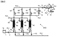
図1は、本発明の膜ろ過装置の一態様における各構成要素が管路で結合された状態を示す側面概略フロー図である。図1において、水処理システムWT1は、原水貯留槽1、前処理膜モジュール4、および、逆浸透膜モジュール7を有する。
FIG. 1 is a side schematic flow diagram illustrating a state in which constituent elements in one embodiment of the membrane filtration device of the present invention are coupled by a pipe line. In FIG. 1, the water treatment system WT1 includes a raw
原水貯留槽1には、原水1aが貯留されている。原水貯留槽1は、その一端(図1においては、左下端)に、原水導出口1cを有する。図示はされていないが、原水貯留槽1には、原水貯留槽1に外部から原水を連続的あるいは間欠的に供給する原水供給管路が接続されている。
In the raw
前処理膜モジュール4は、その内部に、原水をろ過して前処理水と濃縮水に分離するろ過膜4a(例えば、精密ろ過膜、限外ろ過膜、あるいは、これらの双方のろ過膜)を有する。前処理膜モジュール4は、その一端(図1においては、下端)に、原水導入口4bを、その他の一端(図1においては上端)に、前処理水導出口4cを、更に、その他の一端(図1においては周面左側上端)に、濃縮水導出口4dを有する。
The pretreatment membrane module 4 has a
逆浸透膜モジュール7は、その内部に、前処理水をろ過して透過水と濃縮水に分離する逆浸透膜7aを有する。逆浸透膜モジュール7は、その一端(図1においては、左端)に、前処理水導入口7bを、その他の一端(図1においては、右端)に、透過水導出口7cを、更に、その他の一端(図1においては、周面右側下端)に、濃縮水導出口7dを有する。
The reverse
原水貯留槽1の原水導出口1cと前処理膜モジュール4の原水導入口4bは、原水供給管路PL1により結合され、原水供給管路PL1には、原水供給ポンプ2が設けられるとともに、その下流側(原水導入口4b側)に、原水供給弁3が設けられている。また、原水供給管路PL1は、原水供給弁3と原水導入口4bの間の位置に管路分岐点BP1を有し、管路分岐点BP1には、そこから分岐した排水管路PL2が結合されている。排水管路PL2には、排水弁17が設けられている。
The
前処理膜モジュール4の前処理水導出口4cと逆浸透膜モジュール7の前処理水導入口7bは、前処理水が流れる連通管路PL3により結合され、連通管路PL3には、前処理水導出口4cから前処理水導入口7bに向かい、ろ過弁5、加圧ポンプ18、および、取水流量調整弁11が、順次設けられている。
The pretreatment water outlet 4c of the pretreatment membrane module 4 and the pretreatment
連通管路PL3は、ろ過弁5と加圧ポンプ18の間の位置に、管路分岐点BP2を有し、また、前処理水導出口4cとろ過弁5の間の位置に、管路分岐点BP3を有する。管路分岐点BP2と管路分岐点BP3は、分岐管路PL4により、前処理水が、管路分岐点BP2から管路分岐点BP3へと流通可能に結合されているが、分岐管路PL4には、その途中に、前処理水貯留槽14が設けられている。
The communication line PL3 has a pipe branch point BP2 at a position between the
管路分岐点BP2と前処理水貯留槽14の間の分岐管路PL4の前半部分の分岐管路PL4aの下流端は、前処理水貯留槽14の一端(図1においては、上部)に、前処理水貯留槽14への前処理水の供給が可能な状態で、接続されている。前処理水貯留槽14に貯留される前処理水14aは、連通管路PL3から分岐管路PL4aを通り前処理水貯留槽14に供給される。分岐管路PL4aには、管路分岐点BP2から前処理水貯留槽14に向かい、バイパス流量計12とバイパス流量調整弁13が設けられている。バイパス流量計12とバイパス流量調整弁13の間には、流量制御ライン12aが設けられ、流量計が検出したデータに基づき、バイパス流量調整弁13による前処理水貯留槽14に供給される前処理水の流量調整が可能とされている。
The downstream end of the branch pipe PL4a in the first half of the branch pipe PL4 between the pipe branch point BP2 and the pretreatment
前処理水貯留槽14の一端(図1においては、左下端)に、前処理水導出口14cが設けられ、前処理水導出口14cと管路分岐点BP3は、分岐管路PL4の後半部分の分岐管路PL4bにより結合されている。分岐管路PL4bには、前処理水導出口14cから管路分岐点BP3に向かい、逆洗ポンプ15と逆洗弁16が設けられている。
A
前処理膜モジュール4の濃縮水導出口4dには、濃縮水排出管路PL5が結合され、濃縮水排出管路PL5には、エア抜き弁6が設けられている。この濃縮水排出管路PL5は、逆洗水の排出にも使用されるため、逆洗水排出管路と呼称されることもある。
A concentrated water discharge line PL5 is coupled to the
逆浸透膜モジュール7の透過水導出口7cには、透過水導出管路PL6が結合され、透過水導出管路PL6には、透過水流量計8が設けられている。透過水流量計8と連通管路PL3に設けられている取水流量調整弁11の間には、流量制御ライン8aが設けられ、流量計が検出したデータに基づき、取水流量調整弁11による逆浸透膜モジュール7に供給される前処理水の流量調整が可能とされている。
A
逆浸透膜モジュール7の濃縮水導出口7dには、濃縮水排出管路PL7が結合され、濃縮水排出管路PL7には、濃縮水が排出される方向に、濃縮水流量計9と濃縮水流量調整弁10が設けられている。濃縮水流量計9と濃縮水流量調整弁10の間には、流量制御ライン9aが設けられ、流量計が検出したデータに基づき、濃縮水流量調整弁10による逆浸透膜モジュール7から排出される濃縮水の流量調整が可能とされている。
A concentrated water discharge line PL7 is coupled to the
原水供給管路PL1における原水供給弁3は、原水貯留槽1から前処理膜モジュール4へ原水を供給する場合に、開状態とされる。前処理水が流れる連通管路PL3におけるろ過弁5は、前処理膜モジュール4により原水をろ過する場合に、開状態とされる。濃縮水排出管路PL5における排出弁(エア抜き弁)6は、ろ過膜4aを逆圧洗浄や空気洗浄する場合に、開状態とされる。分岐管路PL4bにおける逆洗弁16は、ろ過膜4aを逆圧洗浄する場合に、開状態とされる。排水管路PL2における排水弁17は、前処理膜モジュール4の原水側の水を排出する場合に、開状態とされる。
The raw
水処理システムWT1において、前処理膜モジュール4の前処理水側(前処理水導出口4c)と逆浸透膜モジュール7の取水側(前処理水導入口7b)とが連通管路PL3により直接結合され、連通管路PL3における管路分岐点BP2に、分岐管路PL4(PL4a)が設けられ、分岐管路PL4aに、バイパス水流量計12とバイパス水流量調整弁13が設けられている。バイパス水流量計12が検出する前処理水の流量の値に応じて、流量制御ライン12aを介して、バイパス水流量調整弁13の開度を調整することで、分岐管路PL4aを流れる前処理水の流量を一定流量に制御することができる。
In the water treatment system WT1, the pretreatment water side (pretreatment water outlet 4c) of the pretreatment membrane module 4 and the water intake side (pretreatment
分岐管路PL4の前半部分の分岐管路PL4aの出口(下流端)は、前処理膜逆洗水貯留槽(前処理水貯留槽)14に接続しており、分岐管路PL4aを流れる前処理水は、前処理膜逆洗水貯留槽14に貯留される。前処理膜逆洗水貯留槽14の前処理水導出口14cに接続されている分岐管路PL4の後半部分の分岐管路PL4bには、逆洗ポンプ15が設けられている。逆洗ポンプ15の吐出側は、分岐管路PL4b、管路分岐点BP3、および、連通管路PL3を経て、前処理膜モジュール4の前処理水側(前処理水導出口4c)に接続されている。これにより、前処理膜逆洗水貯留槽14に貯留されている前処理水が、前処理膜モジュール4の前処理水側(前処理水導出口4c)に供給され、前処理膜モジュール4のろ過膜4aの逆洗が行われる。
The outlet (downstream end) of the branch pipe line PL4a in the first half of the branch pipe line PL4 is connected to the pretreatment membrane backwash water storage tank (pretreatment water storage tank) 14, and the pretreatment flowing through the branch pipe line PL4a Water is stored in the pretreatment membrane backwash
図1は側面図であるため、図には示されていないが、図1における水処理システムWT1は、それぞれ並列して位置する独立した複数の前処理膜モジュールを有している。図1では、複数の前処理膜モジュールの内の一番手前にある前処理膜モジュール4が示されている。図1には、逆浸透膜モジュール7が示されているが、複数の前処理膜モジュールのそれぞれから延びるそれぞれの連通管路の下流端の全てが、この逆浸透膜モジュール7に結合されていても良く、あるいは、複数の前処理膜モジュールのそれぞれに対応している図示されていない複数の逆浸透膜モジュールが存在していても良い。
Since FIG. 1 is a side view, it is not shown in the figure, but the water treatment system WT1 in FIG. 1 has a plurality of independent pretreatment membrane modules each positioned in parallel. In FIG. 1, the pretreatment membrane module 4 located in the forefront among the plurality of pretreatment membrane modules is shown. Although the reverse
複数の前処理膜モジュールの内の一部の前処理膜モジュールが、原水のろ過を継続している、すなわち、ろ過工程にある間に、逆洗の必要がある他の前処理膜モジュール、例えば、前処理膜モジュール4のろ過工程を停止して、前処理膜逆洗水貯留槽14に貯留された前処理水を前処理膜モジュール4の前処理水側に流し込み、逆洗の必要がある前処理膜モジュール4のろ過膜4aの逆洗を行うことができる。
Some of the pretreatment membrane modules among the plurality of pretreatment membrane modules continue to filter raw water, i.e. other pretreatment membrane modules that need to be backwashed during the filtration process, for example The filtration process of the pretreatment membrane module 4 is stopped, and the pretreatment water stored in the pretreatment membrane backwash
また、前処理逆洗水貯留槽14と原水貯留槽1を還流管路PL8で接続し、前処理逆洗水貯留槽14内に貯留された前処理水の一部が、原水貯留槽1に還流するようしても構わない。還流管路PL8を備えることで、未使用の前処理水を原水として有効に使用することが可能となり、水処理システムWT1の水回収率を高めることができる。
Further, the pretreatment backwash
次に、図1に示す水処理システムWT1で原水の処理を行う場合の工程を説明する。 Next, the process in the case of processing raw water with the water treatment system WT1 shown in FIG. 1 will be described.
原水貯留槽1に蓄えられた原水1aは、原水供給管路PL1の原水供給弁3が開かれてから、原水供給ポンプ2によって原水導入口4bを経て前処理膜モジュール4の原水側に供給される。前処理膜モジュール4の原水側に溜まっていた空気は、開かれているエア抜き弁6から排出される。空気の排出が完了した後、エア抜き弁6は閉じられ、連通管路PL3のろ過弁5が開かれる。
The
前処理膜モジュール4の前処理水は、前処理水導出口4cから連通管路PL3を流れ、前処理水導入口7bを経て逆浸透膜モジュール7の取水側に供給される。逆浸透膜モジュール7に供給された前処理水は、その一部が逆浸透膜モジュール7の逆浸透膜7aを透過して逆浸透膜透過水となり、残りは溶存塩分等が濃縮された逆浸透膜濃縮水となる。
The pretreatment water of the pretreatment membrane module 4 flows from the pretreatment water outlet 4c through the communication line PL3 and is supplied to the water intake side of the reverse
濃縮水導出口7dから濃縮水排出管路PL7を流れる濃縮水の流量は、濃縮水流量計9が検出する流量の値に応じて流量制御ライン9aにより濃縮水流量調整弁10の開度が調整されることで、制御される。
The flow rate of the concentrated water flowing from the
透過水導出口7cから透過水導出管路PL6を流れる透過水の流量は、透過水流量計8が検出する流量の値に応じて流量制御ライン8aにより取水流量調整弁11の開度が調整されることで、すなわち、連通管路PL3から前処理水導入口7bを経て逆浸透膜モジュール7に流入する前処理水の流量(逆浸透膜モジュール7の取水流量)が調整されることで、制御される。
The flow rate of the permeated water flowing from the permeated
前処理膜モジュール4のろ過膜4aのろ過抵抗上昇を抑えるために定期的に行うろ過膜4aの逆圧洗浄は、次のようにして行われる。図1は側面図であるため、図示されていないが、水処理システムWT1は、個々に独立して並列して設けられた複数の前処理膜モジュールを有する。図1においては、一番手前の前処理膜モジュール4のみが示されている。
The back pressure cleaning of the
そこで、例えば、図示されていない一つの前処理膜モジュールが原水のろ過を継続している状態で、逆圧洗浄が必要となった前処理膜モジュールが図示されている前処理膜モジュール4であるとする。この状態において、逆圧洗浄が必要になった前処理膜モジュール4について、原水供給弁3とろ過弁5とが閉じられ、前処理膜モジュール4による原水のろ過工程が停止される。
Therefore, for example, the pretreatment membrane module 4 shown in the figure is a pretreatment membrane module that requires back pressure cleaning in a state where one pretreatment membrane module (not shown) continues to filter raw water. And In this state, the raw
次いで、濃縮水排出管路PL5のエア抜き弁6と分岐管路PL4bの逆洗弁16が開かれ、分岐管路PL4bの逆洗ポンプ15が作動され、前処理膜逆洗水貯留槽14に蓄えられている前処理水が、分岐管路PL4bから管路分岐点BP3を経て連通管路PL3を通過して、前処理水導出口4cから前処理膜モジュール4の前処理水側に供給される。
Subsequently, the air vent valve 6 of the concentrated water discharge line PL5 and the
前処理膜(ろ過膜)4aを原水のろ過のときとは反対方向に通り抜けた逆洗水(前処理水)は、開かれているエア抜き弁6を経て洗浄排水として濃縮水排出管路PL5通り排出される。この工程は、逆圧洗浄工程と呼称される。所定時間、逆圧洗浄工程が運転された後、逆洗ポンプ15の運転が停止され、逆洗弁16が閉じられる。
The backwash water (pretreatment water) that has passed through the pretreatment membrane (filtration membrane) 4a in the direction opposite to that when the raw water is filtered passes through the open air vent valve 6 and is supplied to the concentrated water discharge line PL5 as washing wastewater. Discharged. This process is called a back pressure washing process. After the back pressure washing process is operated for a predetermined time, the
この逆圧洗浄工程の運転と同時に、あるいは運転停止後引き続いて、図示はされていないが、前処理膜モジュール4の下部に加圧空気が供給され、前処理膜(ろ過膜)4aを揺動させることにより前処理膜(ろ過膜)4aの洗浄がおこなわれる空気洗浄工程が行われても良い。 Simultaneously with the operation of the reverse pressure cleaning process or after the operation stop, although not shown, pressurized air is supplied to the lower portion of the pretreatment membrane module 4 to swing the pretreatment membrane (filtration membrane) 4a. By doing so, an air cleaning step in which the pretreatment membrane (filtration membrane) 4a is washed may be performed.
前処理膜モジュール4のろ過膜4aの逆洗後、排水弁17が開かれ、前処理膜モジュール4の原水側に残留している逆洗水が前処理膜モジュール4から排出される。以上で逆圧洗浄を必要としていた前処理膜モジュール4の逆洗工程の全てが終了する。
After the backwashing of the
次いで、原水供給弁3が開かれ、逆洗が完了した前処理膜モジュール4に原水が供給される。前処理膜モジュール4の原水側に溜まっていた空気は、開けられているエア抜き弁6から排出される。この工程で、前処理膜モジュール4の原水側に保持されていた洗浄排水が、エア抜き弁6を通じて排出されるフラッシング工程を適用することも可能である。その際には、洗浄排水が排水弁17から排出される状態でも、排出されない状態でも構わない。
Next, the raw
エア抜き弁6からの空気の排出が終わってから、エア抜き弁6が閉じられ、ろ過弁5が開かれることで、逆洗が完了した前処理膜モジュール4は、他の前処理膜モジュールと同様に、原水のろ過工程に復帰する。
After the air exhaust from the air vent valve 6 is finished, the air vent valve 6 is closed and the
この逆洗工程において、前処理膜逆洗水貯留槽14に蓄えられた前処理水14aが不足すると、前処理膜モジュール4の逆洗時間が不足して、逆洗効果が小さくなり、前処理膜モジュール4のろ過抵抗が上昇しやすくなったり、逆浸透膜モジュール7による透過水の製造の一部または全部を停止せざるを得なくなったりする。従って、前処理膜逆洗水貯留槽14における前処理水の貯留量は、逆洗に必要とされる前処理水の量に応じたものであることが好ましい。
In this backwashing process, if the
なお、逆洗のための前処理水が不足する場合、別の原水のろ過工程にある前処理膜モジュール系列における前処理水貯留槽に貯留されている前処理水の利用が可能となるように管路を配設して、そこの前処理水を利用することは可能である。しかし、このような逆洗工程を取り入れると、水処理システムWT1の運転が複雑となり、水処理システムWT1の最終目的である逆浸透膜モジュールによる透過水の製造効率の低下をもたらす場合があり、このような逆洗工程は、好ましいとは云えない。 In addition, when the pretreatment water for backwashing is insufficient, the pretreatment water stored in the pretreatment water storage tank in the pretreatment membrane module series in another raw water filtration step can be used. It is possible to use a pretreatment water by arranging a pipeline. However, if such a backwashing process is adopted, the operation of the water treatment system WT1 becomes complicated, and this may lead to a decrease in the production efficiency of the permeated water by the reverse osmosis membrane module that is the final purpose of the water treatment system WT1. Such a backwashing process is not preferred.
一方、逆洗工程が終了した後において、前処理水貯留槽14に残った前処理水を前処理膜の原水側、すなわち、原水貯留槽1に還流させる還流管路PL8を、前処理水貯留槽14と原水貯留槽1との間に設け、前処理水貯留槽14に残った前処理水を原水として使用可能とすることが好ましい。この還流管路PL8は、前処理膜モジュールのろ過運転が継続されている間において、前処理水貯留槽14の前処理水の貯留容量を超える場合に、容量を超えた分の前処理水を原水貯留槽1に還流させるように用いることも可能である。これにより、使用されなかった前処理水の量を減少、あるいは、無くすことができ、水処理システムWT1における水回収率を高めることができる。
On the other hand, after the backwash process is completed, the pretreatment water is stored in the reflux line PL8 for returning the pretreatment water remaining in the pretreatment
ところで、上において、水処理システムWT1が複数の前処理膜モジュールを備えている場合について説明したが、前処理膜モジュールが一つの場合も本発明の態様に含まれる。この場合は、逆洗工程を開始するに当たり、前処理膜モジュール4と逆浸透膜モジュール7からなる1系列の水処理システムによる透過水の製造工程、すなわち、ろ過工程が停止され、ろ過工程中に前処理水貯留槽14に貯留された前処理水により、前処理膜モジュール4のろ過膜4aの逆洗が行われる。
By the way, although the case where the water treatment system WT1 was equipped with the some pretreatment membrane module was demonstrated above, the case where there is one pretreatment membrane module is also contained in the aspect of this invention. In this case, when starting the backwashing process, the permeated water production process by the one-line water treatment system composed of the pretreatment membrane module 4 and the reverse
しかしながら、この態様は、逆洗工程を行うに際して、ろ過工程が完全に停止されるため、水処理システムにおける透過水の製造効率が、上述の複数の前処理膜モジュールが装備され、一つの前処理膜モジュールが逆洗工程にある間にも他の前処理膜モジュールがろ過工程にある水処理システムWT1の場合に比べ、著しく低下する。よって、この態様は、本発明の一態様ではあるが、好ましい態様とは云えない。 However, in this aspect, since the filtration process is completely stopped when the backwashing process is performed, the permeated water production efficiency in the water treatment system is equipped with the plurality of pretreatment membrane modules described above, and one pretreatment is performed. Even when the membrane module is in the backwashing step, it is significantly lower than in the case of the water treatment system WT1 in which the other pretreatment membrane module is in the filtration step. Therefore, this embodiment is an embodiment of the present invention but is not a preferable embodiment.
次に、逆洗を必要とする前処理膜モジュールへの逆洗水(前処理水)の供給量や、逆洗時間に制限は生じるが、本発明の膜ろ過方法、および、膜ろ過装置の別の態様を、図2を参照しながら説明する。 Next, the amount of backwash water (pretreatment water) supplied to the pretreatment membrane module requiring backwash and the backwash time are limited, but the membrane filtration method of the present invention and the membrane filtration device Another aspect is described with reference to FIG.
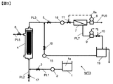
図2は、本発明の膜ろ過装置の別の一態様における各構成要素が管路で結合された状態を示す正面概略フロー図である。図2において、水処理システムWT2は、1つの原水貯留槽1、原水貯留槽1から供給される原水1aをろ過する3つの前処理膜モジュール4A、4B、4C、および、それぞれの前処理膜モジュール4A、4B、4Cにより得られた前処理水をろ過する1つの逆浸透膜モジュール7を有する。
FIG. 2 is a front schematic flow diagram showing a state in which the constituent elements in another aspect of the membrane filtration device of the present invention are coupled by a pipe line. In FIG. 2, the water treatment system WT2 includes one raw
原水貯留槽1と前処理膜モジュール4A、4B、4Cのそれぞれは、原水供給管路PL1により結合されている。原水供給管路PL1には、1つの原水供給ポンプ2と、それぞれの前処理膜モジュール4A、4B、4Cに対応した原水供給弁3A、3B、3Cが設けられている。また、原水供給管路PL1には、それぞれの原水供給弁3A、3B、3Cとそれぞれの前処理膜モジュール4A、4B、4Cの間において分岐した排水管路PL2が設けられている。排水管路PL2には、それぞれの前処理膜モジュール4A、4B、4Cに対応して排水弁17A、17B、17Cが設けられている。
Each of the raw
前処理膜モジュール4A、4B、4Cのそれぞれと、逆浸透膜モジュール7は、連通管路PL3により結合されている。連通管路PL3には、それぞれの前処理膜モジュール4A、4B、4Cに対応したろ過弁5A、5B、5Cと、それらの下流側に1つの加圧ポンプ18と、さらにその下流側に取水流量調整弁11が設けられている。
Each of the
また、連通管路PL3には、ろ過弁5A、5B、5Cと加圧ポンプ18の間の位置において分岐した分岐管路PL4が結合されている。分岐管路PL4の下流端は、それぞれの前処理膜モジュール4A、4B、4Cとそれぞれのろ過弁5A、5B、5Cの間の位置において、連通管路PL3に結合されている。分岐管路PL4には、下流側に向かい、1つのバイパス流量計12、1つのバイパス流量調整弁13、および、それぞれの前処理膜モジュール4A、4B、4Cに対応して、逆洗弁16A、16B、16Cが設けられている。バイパス流量計12とバイパス流量調整弁13の間には、流量制御ライン12aが設けられ、流量計が検出したデータに基づき、バイパス流量調整弁13による前処理水の流量調整が可能とされている。
Further, a branch pipe PL4 branched at a position between the
前処理膜モジュール4A、4B、4Cのそれぞれには、逆洗水排出管路PL5が結合され、逆洗水排出管路PL5には、それぞれの前処理膜モジュール4A、4B、4Cに対応して、排出弁6A、6B、6Cが設けられている。
Each of the
逆浸透膜モジュール7には、透過水導出管路PL6が結合され、透過水導出管路PL6には、透過水流量計8が設けられている。透過水流量計8と連通管路PL3に設けられている取水流量調整弁11の間には、流量制御ライン8aが設けられ、流量計が検出したデータに基づき、取水流量調整弁11による逆浸透膜モジュール7に供給される前処理水の流量調整が可能とされている。
The reverse
逆浸透膜モジュール7には、濃縮水排出管路PL7が結合され、濃縮水排出管路PL7には、濃縮水が排出される方向に、濃縮水流量計9と濃縮水流量調整弁10が設けられている。濃縮水流量計9と濃縮水流量調整弁10の間には、流量制御ライン9aが設けられ、流量計が検出したデータに基づき、濃縮水流量調整弁10による逆浸透膜モジュール7から排出される濃縮水の流量調整が可能とされている。
The reverse
水処理システムWT2は、3つの前処理膜モジュール4A、4B、4Cを有するが、前処理膜モジュールは、必要に応じて、2つあるいは4つ以上であっても良い。また、原水貯留槽および逆浸透膜モジュールも必要に応じて、複数あっても良い。これら要素の管路による結合の仕方は、次に説明する水処理システムWT2における各要素の目的、作用に応じた結合の仕方を参考にして、理解することができる。
The water treatment system WT2 includes three
図2に示す水処理システムWT2が、図1に示す水処理システムWT1と異なる点は、原水供給弁3A、3Bおよび3C、前処理膜モジュール4A、4Bおよび4C、ろ過弁5A、5Bおよび5C、エア抜き弁6A、6Bおよび6C、逆洗弁16A、16Bおよび16C、および排水弁17A、17Bおよび17Cが、互いに並列して設けられている点と、前処理膜モジュールの前処理水側と逆浸透膜モジュールの取水側を結合する連通管路から分岐した分岐管路の前処理膜モジュール4A、4Bおよび4Cに対応したそれぞれの下流端が、逆洗弁16A、16Bおよび16Cを介して、前処理膜モジュール4A、4Bおよび4Cの前処理水側にそれぞれ直接結合している点である。このような構成とすることで、水処理システムWT2では、前処理逆洗水貯留槽14および逆洗ポンプ15を省略することができる。
The water treatment system WT2 shown in FIG. 2 is different from the water treatment system WT1 shown in FIG. 1 in that raw
図1の水処理システムWT1、および、図2の水処理システムWT2において、前処理膜モジュール4の前処理水側と逆浸透膜モジュール7の取水側を結合する連通管路上に、加圧ポンプ18が設けられているが、前処理膜モジュール4の耐圧性が逆浸透膜モジュール7の供給圧力と前処理膜モジュール4の膜間差圧の和の圧力よりも高い場合は、原水供給ポンプ2で、逆浸透膜モジュール7において必要とされる供給圧力に、前処理膜モジュール4の膜間差圧を加えた圧力をかけることで、加圧ポンプ18を省略することができる。
In the water treatment system WT1 of FIG. 1 and the water treatment system WT2 of FIG. 2, a pressurizing
次に、図2に示す水処理システムWT2における、前処理膜モジュール4のろ過抵抗上昇を抑えるために定期的に行う逆圧洗浄方法を行う場合を説明する。 Next, a description will be given of a case where a back-pressure cleaning method that is periodically performed in order to suppress an increase in filtration resistance of the pretreatment membrane module 4 in the water treatment system WT2 illustrated in FIG.
一部の前処理膜モジュール(ここで仮に、前処理膜モジュール4Aおよび4Bとする)が原水のろ過を継続している状態において、逆圧洗浄を行いたい残りの前処理膜モジュール(ここで仮に、前処理膜モジュール4Cとする)について、原水供給弁3Cとろ過弁5Cとを閉にしてろ過を停止し、エア抜き弁6Cと逆洗弁16Cとを開にする。これにより、前処理水の一部が前処理膜モジュール4Cの前処理水側に供給される。
In the state where some of the pretreatment membrane modules (preliminary
バイパス水流量計12における前処理水の流量は、バイパス水流量調整弁13の開度を調整することで、常に、前処理膜モジュール4A、4Bまたは4Cの1つ分の前処理水量と同じに調整されている。
The flow rate of the pretreatment water in the bypass
前処理膜をろ過とは反対方向に通り抜けた逆洗水は、開となっているエア抜き弁6Cを通して、洗浄排水として、前処理膜モジュール4Cから排出されて、前処理膜モジュール4Cの逆圧洗浄工程が開始される。
The backwash water that has passed through the pretreatment membrane in the direction opposite to the filtration is discharged from the
所定時間逆圧洗浄後、次の前処理膜モジュール(ここで仮に、前処理膜モジュール4Aとする)の逆圧洗浄工程に移行する。すなわち、エア抜き弁6Cと逆洗弁16Cとを閉にすると同時に、原水供給弁3Cとろ過弁5Cとを開にして、前処理膜モジュール4Cのろ過を開始し、同時に原水供給弁3Aとろ過弁5Aとを閉にして、前処理膜モジュール4Aのろ過を停止し、同時にエア抜き弁6Aと逆洗弁16Aとを開にする。これにより、前処理水の一部が前処理膜モジュール4Aの前処理水側に供給される。
After the back pressure cleaning for a predetermined time, the process proceeds to the back pressure cleaning process for the next pretreatment membrane module (preliminarily referred to as
前処理膜をろ過とは反対方向に通り抜けた逆洗水は、開となっているエア抜き弁6Aを通して、洗浄排水として、前処理膜モジュール4Aから排出されて、前処理膜モジュール4Aの逆圧洗浄工程が開始される。
The backwash water that has passed through the pretreatment membrane in the direction opposite to the filtration is discharged from the
さらに前処理膜モジュール4Aの所定時間逆圧洗浄後、同様に次の前処理膜モジュール4Bの逆圧洗浄工程に移行し、同様に所定時間逆圧洗浄後、最初の前処理膜モジュール4Cの逆圧洗浄工程に移行し、以下同様の工程を繰り返すことで、すべての前処理膜モジュールに対し、定期的な逆圧洗浄が行われる。
Further, after the
この逆洗と同時に、図示はしないが、前処理膜モジュールの下部に加圧空気を供給し、前処理膜を揺動するように洗浄する空気洗浄工程を行うことも可能である。 At the same time as this backwashing, although not shown, it is also possible to perform an air washing process in which pressurized air is supplied to the lower portion of the pretreatment membrane module and the pretreatment membrane is washed so as to swing.
また、以上3つの前処理膜モジュールについて、前処理膜モジュールの前処理水側に供給される逆洗水量が、前処理膜モジュール1つ分の前処理水量と同じである場合を説明したが、前処理膜モジュールを4つ以上とすることで、逆洗水量を変えることができる。例えば、前処理膜モジュールが4つの場合は、逆圧洗浄工程に同時に移行する前処理膜モジュールが1つのままだと、逆洗水量は前処理膜モジュール1つ分または2つ分を選択でき、逆圧洗浄工程に同時に移行する前処理膜モジュールが2つだと、前処理膜モジュール1つに供給される逆洗水量は、前処理膜モジュール1つ分または0.5個分に選択できる。同様に、前処理膜モジュールの数をさらに増やすことで、逆洗水量の選択肢を増やすことができる。 In addition, for the above three pretreatment membrane modules, the case where the amount of backwash water supplied to the pretreatment water side of the pretreatment membrane module is the same as the amount of pretreatment water for one pretreatment membrane module, By using four or more pretreatment membrane modules, the amount of backwash water can be changed. For example, in the case of four pretreatment membrane modules, if one pretreatment membrane module that moves to the back pressure washing process is left as it is, the amount of backwash water can be selected for one or two pretreatment membrane modules, If there are two pretreatment membrane modules that simultaneously shift to the back pressure washing step, the amount of backwash water supplied to one pretreatment membrane module can be selected to be one pretreatment membrane module or 0.5. Similarly, the options for the amount of backwash water can be increased by further increasing the number of pretreatment membrane modules.
さらに、逆圧洗浄工程に同時に移行させることが必要な前処理膜モジュールが2つ以上の場合には、少なくとも1つの前処理膜モジュールを停止することが可能となるので、空気洗浄工程を逆洗の前後に行ったり、逆洗後、排水弁を開とすることで、前処理膜モジュールの原水側に保持されていた洗浄排水を、前処理膜モジュールから排出したりできる。また、原水供給工程で、前処理膜モジュールの原水側に溜まっていた空気をエア抜き弁から排出したり、さらにこの工程で、前処理膜モジュールの原水側に保持されていた洗浄排水を、エア抜き弁を通じて排出するフラッシング工程を適用することも可能となる。 Furthermore, when there are two or more pretreatment membrane modules that need to be transferred to the back pressure washing step at the same time, it is possible to stop at least one pretreatment membrane module, so the air washing step is backwashed. The cleaning wastewater retained on the raw water side of the pretreatment membrane module can be discharged from the pretreatment membrane module by performing before and after the step or opening the drain valve after backwashing. Also, in the raw water supply process, air accumulated on the raw water side of the pretreatment membrane module is discharged from the air vent valve, and in this step, the cleaning wastewater retained on the raw water side of the pretreatment membrane module is It is also possible to apply a flushing process for discharging through a vent valve.
逆洗工程において、酸化剤を添加する逆洗を行うことや、酸化剤を添加する逆洗を行った後に、継続して酸化剤を添加した逆洗水で前処理膜モジュールの原水側を一定期間浸漬することを、毎回あるいは一定回数毎に行うことも、前処理膜のろ過抵抗の上昇を抑える上で、好ましい。 In the backwashing process, after performing backwashing by adding an oxidizing agent or backwashing by adding an oxidizing agent, the raw water side of the pretreatment membrane module is kept constant with backwashing water to which an oxidizing agent has been added. It is also preferable to perform immersion for a period every time or every certain number of times in order to suppress an increase in filtration resistance of the pretreatment membrane.
前処理膜モジュールに用いられるろ過膜(前処理膜)4aは、0.1μm以上の粒子や高分子を阻止することができる精密ろ過膜や、2nm以上0.1μm未満の粒子や高分子を阻止することができる限外ろ過膜、あるいは、これらと同等の性能を有するろ過膜であれば、特に限定されない。前処理膜モジュールに用いられる精密ろ過膜や限外ろ過膜の形態としては、中空糸膜型、平膜型、スパイラル型、またはチューブラー型を用いることができるが、コスト低減の点から中空糸膜型が好ましい。 The filtration membrane (pretreatment membrane) 4a used in the pretreatment membrane module is a fine filtration membrane capable of blocking particles and polymers of 0.1 μm or more, and blocks particles and polymers of 2 nm or more and less than 0.1 μm. There is no particular limitation as long as it is an ultrafiltration membrane that can be used, or a filtration membrane having performance equivalent to these. As the form of the microfiltration membrane and the ultrafiltration membrane used for the pretreatment membrane module, a hollow fiber membrane type, a flat membrane type, a spiral type, or a tubular type can be used. A membrane type is preferred.
膜ろ過方式としては、全量ろ過型モジュールでもクロスフローろ過型モジュールであっても差し支えないが、エネルギー消費量が少ないという点から全量ろ過型モジュールである方が好ましい。さらに加圧型モジュールであっても浸漬型モジュールであっても差し支えないが、高流束運転が可能であるという点から加圧型モジュールである方が好ましい。また、膜の外側から原水を供給し、内側から透過水を得る外圧式であっても、膜の内側から原水を供給し、外側から透過水を得る内圧式であっても差し支えないが、前処理の簡便さの観点から外圧式である方が好ましい。 The membrane filtration method may be a total filtration module or a cross flow filtration module, but a full filtration module is preferred from the viewpoint of low energy consumption. Furthermore, although it may be a pressurization type module or an immersion type module, the pressurization type module is preferred from the viewpoint that a high flux operation is possible. In addition, it may be an external pressure type that supplies raw water from the outside of the membrane and obtains permeated water from the inside, or an internal pressure type that supplies raw water from the inside of the membrane and obtains permeated water from the outside. From the viewpoint of simplicity of processing, an external pressure type is preferred.
ろ過膜(前処理膜)の素材は、特に限定されない。前処理膜の素材としては、ポリスルホン、ポリエーテルスルホン、ポリアクリロニトリル、ポリイミド、ポリエーテルイミド、ポリアミド、ポリエーテルケトン、ポリエーテルエーテルケトン、ポリエチレン、ポリプロピレン、エチレン−ビニルアルコール共重合体、セルロース、酢酸セルロース、ポリフッ化ビニリデン、エチレン−テトラフルオロエチレン共重合体、ポリテトラフルオロエチレンなどや、これらの複合素材を例示することができる。なかでも、ポリフッ化ビニリデンは、耐薬品性に優れているため、前処理膜を定期的に薬品洗浄することで前処理膜のろ過機能が回復し、前処理膜モジュールの長寿命化につながるので、前処理膜の素材として好ましい。 The material of the filtration membrane (pretreatment membrane) is not particularly limited. Materials for the pretreatment membrane include polysulfone, polyethersulfone, polyacrylonitrile, polyimide, polyetherimide, polyamide, polyetherketone, polyetheretherketone, polyethylene, polypropylene, ethylene-vinyl alcohol copolymer, cellulose, cellulose acetate Polyvinylidene fluoride, ethylene-tetrafluoroethylene copolymer, polytetrafluoroethylene, etc., and composite materials thereof can be exemplified. In particular, polyvinylidene fluoride is superior in chemical resistance, so that the pretreatment membrane filtration function can be recovered by periodically cleaning the pretreatment membrane with chemicals, leading to longer life of the pretreatment membrane module. It is preferable as a material for the pretreatment film.
ろ過膜(前処理膜)が収納される前処理膜モジュールのケースの材質としては、例えば、ポリエチレン、ポリプロピレン、ポリブテン等のポリオレフィンや、ポリテトラフルオロエチレン(PTFE)、テトラフルオロエチレン−パーフルオロアルキルビニルエーテルコポリマー(PFA)、フッ化エチレンポリプロピレンコポリマー(FEP)、エチレンテトラフルオロエチレンコポリマー(ETFE)、ポリクロロトリフルオロエチレン(PCTFE)、三フッ化塩化エチレン−エチレンコポリマー(ECTFE)、ポリフッ化ビニリデン(PVDF)等のフッ素系樹脂、そしてポリ塩化ビニル、ポリ塩化ビニリデン等の塩素樹脂、さらにポリスルホン樹脂、ポリエーテルスルホン樹脂、ポリアリルスルホン樹脂、ポリフェニルエーテル樹脂、アクリロニトリル−ブタジエン−スチレン共重合体樹脂(ABS)、アクリロニトリル−スチレン共重合体樹脂、ポリフェニレンサルファイド樹脂、ポリアミド樹脂、ポリカーボネート樹脂、ポリエーテルケトン樹脂、ポリエーテルエーテルケトン樹脂などが単独または混合して用いられる。また、樹脂以外では、アルミニウム、ステンレス鋼などが好ましく、さらに、樹脂と金属の複合体や、ガラス繊維強化樹脂、炭素繊維強化樹脂などの複合材料を使用してもかまわない。 Examples of the material of the case of the pretreatment membrane module in which the filtration membrane (pretreatment membrane) is accommodated include polyolefins such as polyethylene, polypropylene, polybutene, polytetrafluoroethylene (PTFE), tetrafluoroethylene-perfluoroalkyl vinyl ether Copolymer (PFA), fluorinated ethylene polypropylene copolymer (FEP), ethylene tetrafluoroethylene copolymer (ETFE), polychlorotrifluoroethylene (PCTFE), trifluorochloroethylene-ethylene copolymer (ECTFE), polyvinylidene fluoride (PVDF) Fluorine resin such as polyvinyl chloride, polyvinyl chloride, polyvinyl chloride, and other polysulfone resin, polyethersulfone resin, polyallylsulfone resin, polyphenyl ether Fat, acrylonitrile-butadiene-styrene copolymer resin (ABS), acrylonitrile-styrene copolymer resin, polyphenylene sulfide resin, polyamide resin, polycarbonate resin, polyether ketone resin, polyether ether ketone resin, etc. alone or in combination Used. Other than the resin, aluminum, stainless steel, and the like are preferable, and a composite material such as a resin-metal composite, a glass fiber reinforced resin, and a carbon fiber reinforced resin may be used.
逆浸透膜モジュールは、シート状の膜を集水管の周囲に巻囲したスパイラル型エレメントや、プレート型支持板の両面にシート状の膜を貼ったものをスペーサーを介して一定の間隔で積層してモジュール化したプレート・アンド・フレーム型エレメント、さらには、管状の膜を用いたチューブラー型エレメント、中空糸膜を束ねてケースに収納した中空糸膜エレメントを、耐圧容器に単数もしくは複数個直列に接続して収容して構成される。 The reverse osmosis membrane module is a spiral-type element in which a sheet-like membrane is wrapped around a water collection pipe, or a sheet-type membrane attached on both sides of a plate-type support plate and laminated at regular intervals via spacers. Single and multiple plate and frame type elements, tubular elements using tubular membranes, and hollow fiber membrane elements bundled with hollow fiber membranes and housed in a case Connected to and accommodated.
エレメントの形態としては、いずれの形態であってもよいが、操作性や互換性の観点からは、スパイラル型エレメントを使用するのが好ましい。なお、エレメント本数は、膜性能に応じて、任意に設定することができる。スパイラル型エレメントを用いた場合、1つのモジュールに装填するエレメントの本数は、直列に1本から8本程度に配列することが好ましい。また、逆浸透膜モジュール7を複数本並列に配置しても構わない。
The element may be in any form, but from the viewpoint of operability and compatibility, it is preferable to use a spiral element. The number of elements can be arbitrarily set according to the membrane performance. When spiral type elements are used, the number of elements to be loaded in one module is preferably arranged in a series of about 1 to 8 elements. A plurality of reverse
逆浸透膜モジュールを構成する逆浸透膜については、脱塩性能を有するものであれば、特にどのようなものであっても構わない。膜の素材としては、例えば、ポリアミド系、ポリピペラジンアミド系、ポリエステルアミド系、あるいは水溶性のビニルポリマーを架橋したものなどを使用することができる。 Any reverse osmosis membrane constituting the reverse osmosis membrane module may be used as long as it has desalting performance. As the material of the membrane, for example, polyamide-based, polypiperazine amide-based, polyester amide-based, or water-soluble vinyl polymer crosslinked can be used.
その膜構造としては、膜の少なくとも片面に、緻密層を持ち、緻密層から膜内部あるいはもう片面の膜に向けて徐々に大きな孔径の微細孔を有するもの(非対称膜)や、このような非対称膜の緻密層の上に別の素材で形成された非常に薄い分離機能層を有するもの(複合膜)などを使用することができる。 The membrane structure has a dense layer on at least one side of the membrane, and has fine pores with gradually increasing pore diameters from the dense layer to the inside of the membrane or the membrane on the other side (asymmetric membrane), or such an asymmetric membrane A material having a very thin separation functional layer (composite membrane) formed of another material on the dense layer of the membrane can be used.
しかしながら、高造水量のためには、複合膜であることが好ましく、中でも、透過水量、耐薬品性等の点から、ポリアミド系複合膜が、さらにはピペラジンポリアミド系複合膜が好ましい。 However, in order to increase the amount of water produced, a composite membrane is preferable, and among them, a polyamide-based composite membrane and a piperazine polyamide-based composite membrane are more preferable from the viewpoint of the amount of permeated water and chemical resistance.
外圧式PVDF中空糸膜モジュールHFU−2020(東レ(株)製)を2本、並列に配置して、図示されている前処理膜モジュール4と図示されていない前処理膜モジュールとした。また、スパイラル型逆浸透膜エレメントSU−810(東レ(株)製)を6本直列に装填したものを逆浸透膜モジュール7とした。これらを用いて、図1に示す水処理システムWT1を構成し、以下の条件で実験を行った。
Two external pressure PVDF hollow fiber membrane modules HFU-2020 (manufactured by Toray Industries, Inc.) were arranged in parallel to form a pretreatment membrane module 4 shown in the figure and a pretreatment membrane module not shown in the drawing. A reverse
海水を原水とし、前処理膜モジュール4および他の一つの前処理膜モジュールは、全量ろ過方式とした。膜ろ過工程時間30分の後、2本の前処理膜モジュールの1本ずつを交互に、75L/minの定流量逆圧洗浄工程時間30秒、空気洗浄工程時間30秒、前処理膜モジュール内の原水側の水を全量排出、前処理膜モジュール内の原水側を原水で満水とする順序で洗浄を行い、再び膜ろ過工程に戻る操作を繰り返す運転を行った。また、前処理膜モジュールの前処理水を、分岐管路を通じて、150L/hの定流量で分取し、前処理膜逆洗水貯留槽14に蓄えた。前処理膜逆洗水貯留槽14をオーバーフローした前処理水は、原水貯留槽1に送水した。また、逆浸透膜モジュール7の透過水量を1.4m3/hの定流量、濃縮水量を2.6m3/hの定流量として、逆浸透膜モジュール7の運転を行った。Seawater was used as raw water, and the pretreatment membrane module 4 and the other one pretreatment membrane module were all filtered. After 30 minutes of membrane filtration process time, one each of the two pretreatment membrane modules, alternately, 75 L / min constant flow back pressure washing process time 30 seconds, air washing process time 30 seconds, in the pretreatment membrane module The raw water side was completely discharged, the raw water side in the pretreatment membrane module was washed with the raw water in order, and the operation of returning to the membrane filtration step was repeated. Moreover, the pretreatment water of the pretreatment membrane module was fractionated at a constant flow rate of 150 L / h through the branch pipe and stored in the pretreatment membrane backwash
運転初期、前処理膜モジュールが2本とも膜ろ過工程にあるときのそれぞれの前処理膜モジュールにおける膜差圧は、25℃温度補正差圧で20kPaであった。また、1カ月間運転を行った後の、前処理膜モジュールが2本とも膜ろ過工程にあるときのそれぞれの前処理膜モジュールにおける膜差圧は、25℃温度補正差圧で40kPaであった。この圧力が低いほど、前処理膜モジュールのろ過抵抗上昇が抑えられ、好ましい。また、前処理膜モジュールの逆洗水は、不足することなく、逆浸透膜モジュール7を1カ月間連続して運転をすることができた。
In the initial stage of operation, when both of the pretreatment membrane modules were in the membrane filtration step, the membrane differential pressure in each pretreatment membrane module was 20 kPa at 25 ° C. temperature correction differential pressure. In addition, the membrane pressure difference in each pretreatment membrane module when both of the pretreatment membrane modules were in the membrane filtration step after the operation for one month was 40 kPa at 25 ° C. temperature correction differential pressure. . A lower pressure is preferable because an increase in filtration resistance of the pretreatment membrane module is suppressed. Moreover, the reverse washing water of the pretreatment membrane module was able to operate the reverse
外圧式PVDF中空糸膜モジュールHFU−2020(東レ(株)製)を2本、並列に配置して2つの前処理膜モジュールを用意した。また、スパイラル型逆浸透膜エレメントSU−810(東レ(株)製)を6本直列に装填した逆浸透膜モジュールを用意した。用意したこれらのモジュールを用いて、図3に示す従来の水処理システムWT3を形成した。 Two pre-treatment membrane modules were prepared by arranging two external pressure PVDF hollow fiber membrane modules HFU-2020 (manufactured by Toray Industries, Inc.) in parallel. In addition, a reverse osmosis membrane module in which six spiral reverse osmosis membrane elements SU-810 (manufactured by Toray Industries, Inc.) were loaded in series was prepared. The conventional water treatment system WT3 shown in FIG. 3 was formed using these prepared modules.
図3に示す従来の水処理システムWT3は、逆浸透膜モジュール7の濃縮水を貯留する逆浸透膜濃縮水貯留槽19を有し、逆洗ポンプ15への供給水を逆浸透膜濃縮水としたことと、図1に示す水処理システムWT1における前処理膜モジュール4の前処理水側と逆浸透膜モジュール7の取水側とを結合する連通管路PL3は有するが、この連通管路PL3から分岐した分岐管路PL4は有しない点、従って、分岐管路PL4上にあるバイパス水流量計12、およびバイパス水流量調整弁13を有さない点以外は、図1の水処理システムWT1と同一である。図3に示す従来の水処理システムWT3を用いて、以下の条件で実験を行った。
The conventional water treatment system WT3 shown in FIG. 3 has a reverse osmosis membrane concentrated
海水を原水とし、前処理膜モジュール4および他の一つの前処理膜モジュールは、全量ろ過方式とした。膜ろ過工程時間30分の後、2本の前処理膜モジュールの1本ずつを交互に、逆浸透膜モジュール7の濃縮水を用いた75L/minの定流量逆圧洗浄工程時間30秒、空気洗浄工程時間30秒、中空糸膜モジュール内の原水側の水を全量排出、中空糸膜モジュール内の原水側を原水で満水とする順序で洗浄を行い、再び膜ろ過工程に戻る操作を繰り返す運転を行った。また、逆浸透膜モジュール7の透過水量を1.4m3/hの定流量、濃縮水量を2.6m3/hの定流量として、逆浸透膜モジュール7の運転を行った。Seawater was used as raw water, and the pretreatment membrane module 4 and the other one pretreatment membrane module were all filtered. After 30 minutes of membrane filtration step time, each of the two pretreatment membrane modules is alternately turned into a 75 L / min constant flow back pressure washing step time of 30 seconds using the concentrated water of the reverse
運転初期、前処理膜モジュールが2本とも膜ろ過工程にあるときのそれぞれの前処理膜モジュールにおける膜差圧は、25℃温度補正差圧で20kPaであった。また、1カ月間運転を行った後の、前処理膜モジュールが2本とも膜ろ過工程にあるときのそれぞれの前処理膜モジュールにおける膜差圧は、25℃温度補正差圧で120kPaであった。この膜差圧の値は、実施例1における膜差圧の値の約3倍であり、逆浸透膜モジュールの濃縮水を用いた前処理膜モジュールのろ過膜の逆洗は、好ましいとは云えないことが示された。 In the initial stage of operation, when both of the pretreatment membrane modules were in the membrane filtration step, the membrane differential pressure in each pretreatment membrane module was 20 kPa at 25 ° C. temperature correction differential pressure. In addition, the membrane differential pressure in each pretreatment membrane module when both of the pretreatment membrane modules were in the membrane filtration step after the operation for one month was 120 kPa at 25 ° C. temperature correction differential pressure. . The value of the membrane differential pressure is about three times the value of the membrane differential pressure in Example 1, and it can be said that the backwashing of the filtration membrane of the pretreatment membrane module using the concentrated water of the reverse osmosis membrane module is preferable. Not shown.
本発明の膜ろ過方法、および、膜ろ過装置は、河川水、地下水、下水処理水、あるいは、海水などの原水を、ろ過膜、例えば、精密ろ過膜や限外ろ過膜を備えた前処理膜モジュールでろ過して前処理水を得て、得られた前処理水を逆浸透膜モジュールに供給して工業用水や水道水を製造する浄水プロセスにおいて、前処理膜モジュールの継続的使用により生じるろ過膜の目詰まりによる上昇したろ過抵抗を下げるためのろ過膜の逆洗工程に用いられる逆洗水として、前処理膜モジュールの透過水、すなわち、前処理水を用いる場合における膜ろ過方法、および、膜ろ過装置である。 The membrane filtration method and the membrane filtration device of the present invention are prepared by treating raw water such as river water, groundwater, sewage treated water, or seawater with a filtration membrane, for example, a microfiltration membrane or an ultrafiltration membrane. Filtration caused by continuous use of the pretreatment membrane module in the water purification process in which pretreatment water is obtained by filtering with the module and the obtained pretreatment water is supplied to the reverse osmosis membrane module to produce industrial water and tap water As the backwashing water used in the backwashing process of the filtration membrane to reduce the increased filtration resistance due to clogging of the membrane, the permeated water of the pretreatment membrane module, that is, the membrane filtration method when using the pretreatment water, and It is a membrane filtration device.
特に、複数の前処理膜モジュールが用いられる場合、一つの前処理膜モジュールが逆洗工程にあっても、他の前処理膜モジュールのろ過工程が維持可能で、従って、必要とされる逆洗工程は行われるものの、その間においても、逆浸透膜モジュールによる浄水プロセスの継続が可能である。 In particular, when a plurality of pretreatment membrane modules are used, even if one pretreatment membrane module is in the backwashing step, the filtration step of other pretreatment membrane modules can be maintained, and thus the required backwashing is required. Although the process is performed, the water purification process by the reverse osmosis membrane module can be continued even in the meantime.
1:原水貯留槽
1a:原水
1c:原水導出口
2:原水供給ポンプ
3、3A、3B、3C:原水供給弁
4、4A、4B、4C:前処理膜モジュール
4a:ろ過膜
4b:原水導入口
4c:前処理水導出口
4d:濃縮水導出口
5、5A、5B、5C:ろ過弁
6、6A、6B、6C:排出弁(エア抜き弁)
7:逆浸透膜モジュール
7a:逆浸透膜
7b:前処理水導入口
7c:透過水導出口
7d:濃縮水導出口
8:透過水流量計
8a:流量制御ライン
9:濃縮水流量計
9a:流量制御ライン
10:濃縮水流量調整弁
11:取水流量調整弁
12:バイパス流量計
12a:流量制御ライン
13:バイパス流量調整弁
14:前処理水貯留槽(前処理膜逆洗水貯留槽)
14a:前処理水
14c:前処理水導出口
15:逆洗ポンプ
16、16A、16B、16C:逆洗弁
17、17A、17B、17C:排水弁
18:加圧ポンプ
BP1、BP2、BP3:管路分岐点
PL1:原水供給管路
PL2:排水管路
PL3:連通管路
PL4、PL4a、PL4b:分岐管路
PL5:濃縮水排出管路
PL6:透過水導出管路
PL7:濃縮水排出管路
PL8:還流管路
WT1、WT2、WT3:水処理システム1: Raw
7: Reverse
14a:
Claims (2)
前記前処理膜モジュールにおける前記前処理水の導出口と前記逆浸透膜モジュールにおける前記前処理水の導入口を直接結合する連通管路が設けられるとともに、該連通管路を流れる前記前処理水の一部を該連通管路から導出する分岐管路が設けられ、前記分岐管路にはバイパス流量計とバイパス流量調整弁とが設けられ、かつ、
前記分岐管路の下流端が、直接前記前処理膜モジュールの前記前処理水の導出口に結合されている前記連通管路に接続され、前記分岐管路を流れる前記前処理水により、前記ろ過膜の逆洗を必要とする前記前処理膜モジュールの前記ろ過膜の逆洗が行われ、前記逆洗に用いられる逆洗水の流量は、前記バイパス流量計が検出したデータに基づき、前記バイパス流量調整弁により調整されることを特徴とする膜ろ過方法。 It consists of two or more pretreatment membrane modules provided with a filtration membrane for filtering raw water, and one or two or more reverse osmosis membrane modules provided with a reverse osmosis membrane for filtering pretreatment water obtained by the pretreatment membrane module. The raw water is supplied to the pretreatment membrane module, the raw water is separated into pretreatment water and concentrated water by the filtration membrane, and the obtained pretreatment water is supplied to the reverse osmosis membrane module, and the pretreatment In a membrane filtration method in a water treatment system in which water is separated into permeated water and concentrated water by the reverse osmosis membrane,
A communication conduit that directly connects the pretreatment water outlet in the pretreatment membrane module and the pretreatment water introduction port in the reverse osmosis membrane module is provided, and the pretreatment water that flows through the communication conduit A branch pipe that partially leads out from the communication pipe is provided, the branch pipe is provided with a bypass flow meter and a bypass flow rate adjustment valve; and
The downstream end of the branch pipe is directly connected to the communication pipe connected to the outlet of the pretreatment water of the pretreatment membrane module, and the filtration is performed by the pretreatment water flowing through the branch pipe. The filtration membrane of the pretreatment membrane module that requires backwashing of the membrane is backwashed, and the flow rate of backwash water used for the backwash is based on the data detected by the bypass flow meter. A membrane filtration method characterized by being regulated by a flow rate regulating valve.
前記前処理膜モジュールにおける前記前処理水の導出口と前記逆浸透膜モジュールにおける前記前処理水の導入口を直接結合する連通管路が設けられるとともに、該連通管路を流れる前記前処理水の一部を該連通管路から導出する分岐管路が設けられ、前記分岐管路にはバイパス流量計とバイパス流量調整弁とが設けられ、かつ、
前記分岐管路の下流端が、直接前記前処理膜モジュールの前記前処理水の導出口に結合されている前記連通管路に接続され、前記分岐管路を流れる前記前処理水により、前記ろ過膜の逆洗を必要とする前記前処理膜モジュールの前記ろ過膜の逆洗が行われることを特徴とする膜ろ過装置。 Two or more pretreatment membrane modules provided with a raw water storage tank, a filtration membrane for filtering raw water supplied from the raw water storage tank, and a reverse osmosis membrane for filtering pretreatment water obtained by the pretreatment membrane module The pretreated water obtained by comprising one or two or more reverse osmosis membrane modules provided, the raw water being supplied to the pretreated membrane module, and the raw water being separated into pretreated water and concentrated water by the filtration membrane. Is supplied to the reverse osmosis membrane module, and the membrane filtration device in the water treatment system in which the pretreated water is separated into permeated water and concentrated water by the reverse osmosis membrane,
A communication conduit that directly connects the pretreatment water outlet in the pretreatment membrane module and the pretreatment water introduction port in the reverse osmosis membrane module is provided, and the pretreatment water that flows through the communication conduit A branch pipe that partially leads out from the communication pipe is provided, the branch pipe is provided with a bypass flow meter and a bypass flow rate adjustment valve; and
The downstream end of the branch pipe is directly connected to the communication pipe connected to the outlet of the pretreatment water of the pretreatment membrane module, and the filtration is performed by the pretreatment water flowing through the branch pipe. The membrane filtration apparatus, wherein the filtration membrane of the pretreatment membrane module requiring membrane backwashing is backwashed.
Applications Claiming Priority (3)
| Application Number | Priority Date | Filing Date | Title |
|---|---|---|---|
| JP2011143849 | 2011-06-29 | ||
| JP2011143849 | 2011-06-29 | ||
| PCT/JP2012/066340 WO2013002244A1 (en) | 2011-06-29 | 2012-06-27 | Membrane filtration method and membrane filtration device |
Publications (2)
| Publication Number | Publication Date |
|---|---|
| JPWO2013002244A1 JPWO2013002244A1 (en) | 2015-02-23 |
| JP6020168B2 true JP6020168B2 (en) | 2016-11-02 |
Family
ID=47424135
Family Applications (1)
| Application Number | Title | Priority Date | Filing Date |
|---|---|---|---|
| JP2012531145A Active JP6020168B2 (en) | 2011-06-29 | 2012-06-27 | Membrane filtration method and membrane filtration apparatus |
Country Status (8)
| Country | Link |
|---|---|
| US (1) | US20140131281A1 (en) |
| EP (1) | EP2727644A4 (en) |
| JP (1) | JP6020168B2 (en) |
| KR (1) | KR20140040173A (en) |
| CN (1) | CN103619450A (en) |
| AU (1) | AU2012276702B2 (en) |
| CA (1) | CA2840477A1 (en) |
| WO (1) | WO2013002244A1 (en) |
Families Citing this family (19)
| Publication number | Priority date | Publication date | Assignee | Title |
|---|---|---|---|---|
| KR101500692B1 (en) * | 2013-04-11 | 2015-03-09 | 주식회사 아이디티인터내셔널 | Method and apparatus for manufacturing graphite oxide |
| JP2014217821A (en) * | 2013-05-10 | 2014-11-20 | 尚之 生田 | Filter device for drinking water |
| AU2015259228B2 (en) | 2014-05-13 | 2020-04-23 | Amgen Inc. | Process control systems and methods for use with filters and filtration processes |
| CN104324614B (en) * | 2014-08-08 | 2018-02-06 | 唐山海清源科技股份有限公司 | Spliced pressure vessel for reverse osmosis, reverse osmosis membrane assembly and equipment and reverse osmosis |
| AT516362B1 (en) * | 2014-09-16 | 2021-05-15 | Deltacore Gmbh | Device for continuous water filtration with automatic filter cleaning |
| KR101802600B1 (en) * | 2015-10-21 | 2017-11-28 | 두산중공업 주식회사 | water purifying system and backwash module control method thereof |
| WO2017115423A1 (en) * | 2015-12-28 | 2017-07-06 | 三菱重工業株式会社 | Water treatment system and water treatment method |
| IL265378B (en) * | 2016-09-15 | 2022-07-01 | Fluence Water Israel Ltd | Containerized desalination system |
| CN107990023B (en) | 2016-10-26 | 2019-11-26 | 3M创新有限公司 | Reversal valve and household water filter including the reversal valve |
| WO2018200434A1 (en) * | 2017-04-26 | 2018-11-01 | Bl Technologies, Inc. | High recovery integrated uf/ro system |
| JP7197260B2 (en) * | 2017-09-12 | 2022-12-27 | 旭化成株式会社 | Hollow fiber membrane module, seawater desalination system, method for desalinating seawater, method for producing freshwater from seawater, method for operating hollow fiber membrane module, method for filtration, and method for manufacturing hollow fiber membrane module |
| WO2019216326A1 (en) | 2018-05-11 | 2019-11-14 | 旭化成株式会社 | Method for washing filter and method for desalinating seawater |
| US20200140307A1 (en) * | 2018-11-01 | 2020-05-07 | Crane Engineering Sales, Inc. | Compact High Throughput Filtering Systems for Wastewater |
| CN109534446A (en) * | 2018-12-04 | 2019-03-29 | 北京燕脉龙科技有限公司 | A kind of Ro reverse osmosis concentrated water recycling processing system |
| JP2020134044A (en) * | 2019-02-21 | 2020-08-31 | 栗田工業株式会社 | Outdoor unit cooling auxiliary device and outdoor unit cooling auxiliary method |
| CN112441670A (en) * | 2019-08-28 | 2021-03-05 | 杜宁峻 | Water purifier water storage periodical water changing method during off-stream period |
| JP2023501760A (en) | 2019-11-22 | 2023-01-19 | イルミナ インコーポレイテッド | A circulating RNA signature specific to pre-eclampsia |
| US11261102B2 (en) * | 2020-05-01 | 2022-03-01 | Jacob H. Berg | Reverse osmosis prefilter system |
| CN116507590A (en) * | 2020-12-21 | 2023-07-28 | 威乐欧洲股份公司 | Ultrafiltration device and reflux flushing method |
Family Cites Families (13)
| Publication number | Priority date | Publication date | Assignee | Title |
|---|---|---|---|---|
| JPH10263539A (en) | 1997-03-28 | 1998-10-06 | Japan Organo Co Ltd | Member treating method of water to be treated and membrane treating device |
| US6508936B1 (en) * | 1997-10-01 | 2003-01-21 | Saline Water Conversion Corporation | Process for desalination of saline water, especially water, having increased product yield and quality |
| DE60043669D1 (en) * | 1999-10-27 | 2010-02-25 | Nukem Technologies Gmbh | APPENDIX FOR THE TREATMENT OF WASTEWATER |
| JP2001347268A (en) * | 2000-06-06 | 2001-12-18 | Mitsubishi Rayon Co Ltd | Water treatment equipment |
| CN1245249C (en) * | 2001-09-18 | 2006-03-15 | 天津膜天膜工程技术有限公司 | Hollow fiber membrane separator and its running process |
| EP1329425A1 (en) * | 2002-01-18 | 2003-07-23 | Toray Industries, Inc. | Desalination method and desalination apparatus |
| GB0312394D0 (en) * | 2003-05-30 | 2003-07-02 | Weir Westgarth Ltd | Filtration apparatus and method |
| JP2007130523A (en) * | 2005-11-08 | 2007-05-31 | Kobelco Eco-Solutions Co Ltd | Membrane washing method for water treatment system |
| JP2007181822A (en) * | 2006-12-19 | 2007-07-19 | Kobelco Eco-Solutions Co Ltd | Water treatment system for producing drinking water and its operation method |
| GB0702214D0 (en) * | 2007-02-06 | 2007-03-14 | H2Oil & Gas Ltd | Filtration system |
| JP2011020029A (en) * | 2009-07-14 | 2011-02-03 | Miura Co Ltd | Pure water production system |
| JP2011056412A (en) * | 2009-09-10 | 2011-03-24 | Toshiba Corp | Membrane filtration system |
| JP5420451B2 (en) * | 2010-03-01 | 2014-02-19 | 旭化成ケミカルズ株式会社 | Filtration device |
-
2012
- 2012-06-27 AU AU2012276702A patent/AU2012276702B2/en not_active Ceased
- 2012-06-27 CN CN201280031141.9A patent/CN103619450A/en active Pending
- 2012-06-27 EP EP12803970.8A patent/EP2727644A4/en not_active Withdrawn
- 2012-06-27 WO PCT/JP2012/066340 patent/WO2013002244A1/en active Application Filing
- 2012-06-27 US US14/128,960 patent/US20140131281A1/en not_active Abandoned
- 2012-06-27 JP JP2012531145A patent/JP6020168B2/en active Active
- 2012-06-27 KR KR1020137034454A patent/KR20140040173A/en not_active Application Discontinuation
- 2012-06-27 CA CA2840477A patent/CA2840477A1/en not_active Abandoned
Also Published As
| Publication number | Publication date |
|---|---|
| AU2012276702A1 (en) | 2014-01-23 |
| AU2012276702B2 (en) | 2017-02-09 |
| CN103619450A (en) | 2014-03-05 |
| CA2840477A1 (en) | 2013-01-03 |
| EP2727644A1 (en) | 2014-05-07 |
| EP2727644A4 (en) | 2015-02-18 |
| WO2013002244A1 (en) | 2013-01-03 |
| US20140131281A1 (en) | 2014-05-15 |
| JPWO2013002244A1 (en) | 2015-02-23 |
| KR20140040173A (en) | 2014-04-02 |
Similar Documents
| Publication | Publication Date | Title |
|---|---|---|
| JP6020168B2 (en) | Membrane filtration method and membrane filtration apparatus | |
| JP5549589B2 (en) | Fresh water system | |
| US9259686B2 (en) | Water producing system and operation method therefor | |
| JP5804228B1 (en) | Water treatment method | |
| JP5821838B2 (en) | Hollow fiber membrane filtration device and method for cleaning hollow fiber membrane module | |
| WO2011016410A1 (en) | Water treatment device and water treatment method | |
| WO1999065594A1 (en) | Spiral reverse osmosis membrane element, reverse osmosis membrane module using it, device and method for reverse osmosis separation incorporating the module | |
| JP6699554B2 (en) | Fresh water producing apparatus and method of operating fresh water producing apparatus | |
| JP2003181247A (en) | Treatment system having spiral membrane element and its operating method | |
| JP5962513B2 (en) | Fresh water production apparatus and fresh water production method | |
| US10583401B2 (en) | Integrated ultrafiltration and reverse osmosis desalination systems | |
| JP6441808B2 (en) | Desalination apparatus and desalination method | |
| WO2012098969A1 (en) | Method for cleaning membrane module, method of fresh water generation, and fresh water generator | |
| JP6183213B2 (en) | Fresh water generation method and fresh water generation apparatus | |
| JP6087667B2 (en) | Desalination method and desalination apparatus | |
| JP6191464B2 (en) | Operation method of turbidity removal membrane module | |
| KR101732811B1 (en) | Energy saving Forward Osmosis-filtration hybrid Water treatment/seawater desalination system using big size polymer draw solute and method of Water treatment/seawater desalination using the same | |
| JP2015182054A (en) | Fresh water production apparatus and method of cleaning reverse osmosis membrane unit | |
| WO2021241620A1 (en) | Hollow fiber membrane replacing method |
Legal Events
| Date | Code | Title | Description |
|---|---|---|---|
| RD02 | Notification of acceptance of power of attorney |
Free format text: JAPANESE INTERMEDIATE CODE: A7422 Effective date: 20150123 |
|
| A621 | Written request for application examination |
Free format text: JAPANESE INTERMEDIATE CODE: A621 Effective date: 20150428 |
|
| A131 | Notification of reasons for refusal |
Free format text: JAPANESE INTERMEDIATE CODE: A131 Effective date: 20151201 |
|
| A521 | Request for written amendment filed |
Free format text: JAPANESE INTERMEDIATE CODE: A523 Effective date: 20160126 |
|
| A131 | Notification of reasons for refusal |
Free format text: JAPANESE INTERMEDIATE CODE: A131 Effective date: 20160426 |
|
| A521 | Request for written amendment filed |
Free format text: JAPANESE INTERMEDIATE CODE: A523 Effective date: 20160620 |
|
| TRDD | Decision of grant or rejection written | ||
| A01 | Written decision to grant a patent or to grant a registration (utility model) |
Free format text: JAPANESE INTERMEDIATE CODE: A01 Effective date: 20160906 |
|
| A61 | First payment of annual fees (during grant procedure) |
Free format text: JAPANESE INTERMEDIATE CODE: A61 Effective date: 20160919 |
|
| R151 | Written notification of patent or utility model registration |
Ref document number: 6020168 Country of ref document: JP Free format text: JAPANESE INTERMEDIATE CODE: R151 |