JP6017162B2 - Disc brake device - Google Patents
Disc brake device Download PDFInfo
- Publication number
- JP6017162B2 JP6017162B2 JP2012081535A JP2012081535A JP6017162B2 JP 6017162 B2 JP6017162 B2 JP 6017162B2 JP 2012081535 A JP2012081535 A JP 2012081535A JP 2012081535 A JP2012081535 A JP 2012081535A JP 6017162 B2 JP6017162 B2 JP 6017162B2
- Authority
- JP
- Japan
- Prior art keywords
- value
- electric motor
- piston
- current value
- brake
- Prior art date
- Legal status (The legal status is an assumption and is not a legal conclusion. Google has not performed a legal analysis and makes no representation as to the accuracy of the status listed.)
- Active
Links
Images


Classifications
-
- B—PERFORMING OPERATIONS; TRANSPORTING
- B60—VEHICLES IN GENERAL
- B60T—VEHICLE BRAKE CONTROL SYSTEMS OR PARTS THEREOF; BRAKE CONTROL SYSTEMS OR PARTS THEREOF, IN GENERAL; ARRANGEMENT OF BRAKING ELEMENTS ON VEHICLES IN GENERAL; PORTABLE DEVICES FOR PREVENTING UNWANTED MOVEMENT OF VEHICLES; VEHICLE MODIFICATIONS TO FACILITATE COOLING OF BRAKES
- B60T13/00—Transmitting braking action from initiating means to ultimate brake actuator with power assistance or drive; Brake systems incorporating such transmitting means, e.g. air-pressure brake systems
- B60T13/74—Transmitting braking action from initiating means to ultimate brake actuator with power assistance or drive; Brake systems incorporating such transmitting means, e.g. air-pressure brake systems with electrical assistance or drive
- B60T13/741—Transmitting braking action from initiating means to ultimate brake actuator with power assistance or drive; Brake systems incorporating such transmitting means, e.g. air-pressure brake systems with electrical assistance or drive acting on an ultimate actuator
-
- F—MECHANICAL ENGINEERING; LIGHTING; HEATING; WEAPONS; BLASTING
- F16—ENGINEERING ELEMENTS AND UNITS; GENERAL MEASURES FOR PRODUCING AND MAINTAINING EFFECTIVE FUNCTIONING OF MACHINES OR INSTALLATIONS; THERMAL INSULATION IN GENERAL
- F16D—COUPLINGS FOR TRANSMITTING ROTATION; CLUTCHES; BRAKES
- F16D65/00—Parts or details
- F16D65/14—Actuating mechanisms for brakes; Means for initiating operation at a predetermined position
- F16D65/16—Actuating mechanisms for brakes; Means for initiating operation at a predetermined position arranged in or on the brake
- F16D65/18—Actuating mechanisms for brakes; Means for initiating operation at a predetermined position arranged in or on the brake adapted for drawing members together, e.g. for disc brakes
-
- B—PERFORMING OPERATIONS; TRANSPORTING
- B60—VEHICLES IN GENERAL
- B60T—VEHICLE BRAKE CONTROL SYSTEMS OR PARTS THEREOF; BRAKE CONTROL SYSTEMS OR PARTS THEREOF, IN GENERAL; ARRANGEMENT OF BRAKING ELEMENTS ON VEHICLES IN GENERAL; PORTABLE DEVICES FOR PREVENTING UNWANTED MOVEMENT OF VEHICLES; VEHICLE MODIFICATIONS TO FACILITATE COOLING OF BRAKES
- B60T13/00—Transmitting braking action from initiating means to ultimate brake actuator with power assistance or drive; Brake systems incorporating such transmitting means, e.g. air-pressure brake systems
- B60T13/74—Transmitting braking action from initiating means to ultimate brake actuator with power assistance or drive; Brake systems incorporating such transmitting means, e.g. air-pressure brake systems with electrical assistance or drive
-
- F—MECHANICAL ENGINEERING; LIGHTING; HEATING; WEAPONS; BLASTING
- F16—ENGINEERING ELEMENTS AND UNITS; GENERAL MEASURES FOR PRODUCING AND MAINTAINING EFFECTIVE FUNCTIONING OF MACHINES OR INSTALLATIONS; THERMAL INSULATION IN GENERAL
- F16D—COUPLINGS FOR TRANSMITTING ROTATION; CLUTCHES; BRAKES
- F16D65/00—Parts or details
- F16D65/02—Braking members; Mounting thereof
- F16D65/04—Bands, shoes or pads; Pivots or supporting members therefor
- F16D65/092—Bands, shoes or pads; Pivots or supporting members therefor for axially-engaging brakes, e.g. disc brakes
- F16D65/095—Pivots or supporting members therefor
-
- F—MECHANICAL ENGINEERING; LIGHTING; HEATING; WEAPONS; BLASTING
- F16—ENGINEERING ELEMENTS AND UNITS; GENERAL MEASURES FOR PRODUCING AND MAINTAINING EFFECTIVE FUNCTIONING OF MACHINES OR INSTALLATIONS; THERMAL INSULATION IN GENERAL
- F16D—COUPLINGS FOR TRANSMITTING ROTATION; CLUTCHES; BRAKES
- F16D65/00—Parts or details
- F16D65/14—Actuating mechanisms for brakes; Means for initiating operation at a predetermined position
- F16D65/16—Actuating mechanisms for brakes; Means for initiating operation at a predetermined position arranged in or on the brake
- F16D65/18—Actuating mechanisms for brakes; Means for initiating operation at a predetermined position arranged in or on the brake adapted for drawing members together, e.g. for disc brakes
- F16D65/183—Actuating mechanisms for brakes; Means for initiating operation at a predetermined position arranged in or on the brake adapted for drawing members together, e.g. for disc brakes with force-transmitting members arranged side by side acting on a spot type force-applying member
-
- F—MECHANICAL ENGINEERING; LIGHTING; HEATING; WEAPONS; BLASTING
- F16—ENGINEERING ELEMENTS AND UNITS; GENERAL MEASURES FOR PRODUCING AND MAINTAINING EFFECTIVE FUNCTIONING OF MACHINES OR INSTALLATIONS; THERMAL INSULATION IN GENERAL
- F16D—COUPLINGS FOR TRANSMITTING ROTATION; CLUTCHES; BRAKES
- F16D65/00—Parts or details
- F16D65/38—Slack adjusters
- F16D65/40—Slack adjusters mechanical
- F16D65/52—Slack adjusters mechanical self-acting in one direction for adjusting excessive play
- F16D65/56—Slack adjusters mechanical self-acting in one direction for adjusting excessive play with screw-thread and nut
-
- F—MECHANICAL ENGINEERING; LIGHTING; HEATING; WEAPONS; BLASTING
- F16—ENGINEERING ELEMENTS AND UNITS; GENERAL MEASURES FOR PRODUCING AND MAINTAINING EFFECTIVE FUNCTIONING OF MACHINES OR INSTALLATIONS; THERMAL INSULATION IN GENERAL
- F16D—COUPLINGS FOR TRANSMITTING ROTATION; CLUTCHES; BRAKES
- F16D2121/00—Type of actuator operation force
- F16D2121/02—Fluid pressure
-
- F—MECHANICAL ENGINEERING; LIGHTING; HEATING; WEAPONS; BLASTING
- F16—ENGINEERING ELEMENTS AND UNITS; GENERAL MEASURES FOR PRODUCING AND MAINTAINING EFFECTIVE FUNCTIONING OF MACHINES OR INSTALLATIONS; THERMAL INSULATION IN GENERAL
- F16D—COUPLINGS FOR TRANSMITTING ROTATION; CLUTCHES; BRAKES
- F16D2121/00—Type of actuator operation force
- F16D2121/18—Electric or magnetic
- F16D2121/24—Electric or magnetic using motors
-
- F—MECHANICAL ENGINEERING; LIGHTING; HEATING; WEAPONS; BLASTING
- F16—ENGINEERING ELEMENTS AND UNITS; GENERAL MEASURES FOR PRODUCING AND MAINTAINING EFFECTIVE FUNCTIONING OF MACHINES OR INSTALLATIONS; THERMAL INSULATION IN GENERAL
- F16D—COUPLINGS FOR TRANSMITTING ROTATION; CLUTCHES; BRAKES
- F16D2123/00—Multiple operation forces
Description
本発明は、駐車ブレーキ機構を有するディスクブレーキ装置に関するものである。 The present invention relates to a disc brake device having a parking brake mechanism.
駐車ブレーキ機構を有するディスクブレーキ装置のうち、電動モータによって駐車ブレーキの制御を行うものとして特許文献1に記載のものがある。該特許文献1のディスクブレーキ装置では、駐車ブレーキ作動状態を運転者のスイッチ操作等により解除するための駐車ブレーキのリリース動作を行うようになっている。リリース動作は、ピストンを推進する推進部材(ランプボディ)を後退させるべく、リリース方向へのモータ回転駆動時間がスイッチ操作から所定時間経過したときに、電動モータの回転を停止してリリース動作が終了するようになっている。 Among disk brake devices having a parking brake mechanism, there is one described in Patent Document 1 that controls a parking brake by an electric motor. In the disc brake device of Patent Document 1, a parking brake release operation for releasing the parking brake operation state by a driver's switch operation or the like is performed. In the release operation, when the motor rotation drive time in the release direction elapses a predetermined time from the switch operation in order to retract the propulsion member (lamp body) that propels the piston, the rotation of the electric motor stops and the release operation ends. It is supposed to be.
しかしながら、特許文献1のものでは、駐車ブレーキのリリース動作時電動モータを回転させる時間が一定時間に設定されているが、機械的構造上の寸法のバラツキや温度特性によりリリースのためのモータ回転駆動時間を適切に設定することは困難を要する。すなわち、特許文献1のものでは、駐車ブレーキのリリース動作時のモータの回転量に過不足が生じる可能性がある。例えば、電動モータが過度に回転した場合には、ピストンと推進部材とのクリアランス量が過剰になる。このため、次の駐車ブレーキ作動時に時間を要してしまうという問題が発生する。一方、電動モータの回転量が不足した場合には、ピストンと推進部材とのクリアランス量が不足する。このため、車両走行中のディスクロータの面振れによりブレーキパッドを介してピストンが後退しようとしても推進部材によりその後退が妨げられ、結果的にディスクロータとブレーキパッドが接触状態となる、いわゆる、引き摺りが発生するという問題が発生する。 However, in Patent Document 1, the time for rotating the electric motor during the release operation of the parking brake is set to a fixed time. However, the motor rotation drive for the release is performed due to the variation in the dimensions of the mechanical structure and the temperature characteristics. It is difficult to set the time appropriately. That is, in the thing of patent document 1, excess and deficiency may arise in the rotation amount of the motor at the time of release operation of a parking brake. For example, when the electric motor rotates excessively, the clearance amount between the piston and the propelling member becomes excessive. For this reason, the problem that time will be required at the time of the next parking brake action | operation will generate | occur | produce. On the other hand, when the rotation amount of the electric motor is insufficient, the clearance amount between the piston and the propulsion member is insufficient. For this reason, even if the piston tries to retreat via the brake pad due to the surface vibration of the disk rotor while the vehicle is running, the propulsion member prevents the retreat, so that the disk rotor and the brake pad are brought into contact with each other. The problem that occurs.
本発明は、かかる点に鑑みてなされたものであり、駐車ブレーキのリリース動作の終了に伴うピストンと推進部材とのクリアランス量を適正にし得るディスクブレーキ装置を提供することを目的とする。 The present invention has been made in view of this point, and an object of the present invention is to provide a disc brake device that can make the clearance amount between the piston and the propelling member appropriate when the release operation of the parking brake ends.
上記課題を解決するための手段として、ディスクブレーキ装置は、ディスクの両面に配置されるブレーキパッドを液圧シリンダ内に設けられたピストンにより押圧するキャリパと、該キャリパに設けられ電動モータによりピストンを推進させる推進部材を有するピストン推進機構と、推進したピストンを保持するピストン保持機構と、前記電動モータの駆動を制御する制御手段と、を有し、前記制御手段は、前記ピストン保持機構によるピストンの保持を解除するべく前記電動モータを駆動した後に、前記ブレーキパッドが前記ディスクから離脱したことを検知してから、前記ブレーキパッドが前記ディスクから離脱したことの検知以降の前記電動モータの電流値に基づく検出値の積分値分該電動モータを駆動したとき、該電動モータの駆動を停止するものである。
As means for solving the above problems, a disc brake device includes a caliper that presses brake pads arranged on both sides of a disc with a piston provided in a hydraulic cylinder, and a piston that is provided on the caliper with an electric motor. A piston propulsion mechanism having a propulsion member to be propelled; a piston holding mechanism that holds the propelled piston; and a control unit that controls driving of the electric motor. The control unit includes: After driving the electric motor to release the holding, the current value of the electric motor after the detection that the brake pad is detached from the disk is detected after detecting that the brake pad is detached from the disk. when driving the integration value component the electric motor of the detection value based, driving of the electric motor It is intended to stop.
本発明のディスクブレーキ装置によれば、駐車ブレーキのリリース動作の終了時点でのピストンと推進部材とのクリアランス量を適正にすることができる。 According to the disc brake device of the present invention, the clearance amount between the piston and the propulsion member at the end of the release operation of the parking brake can be made appropriate.
以下、実施形態を図1〜図9に基づいて詳細に説明する。
図1には、本実施形態に係るディスクブレーキ装置1が搭載されるブレーキシステムが示されている。ディスクブレーキ装置1は、図1に示すように、後輪に制動力を発生させる駐車ブレーキ付きディスクブレーキ2、2と、駐車ブレーキに係る制御手段としての駐車ブレーキ制御装置4とから構成されている。そして、ブレーキシステムは全体として、ディスクブレーキ装置1の他に、前輪に制動力を発生させるディスクブレーキ10、10と、ドライバがブレーキ操作を行うブレーキペダル11の踏み込みにより液圧を発生するマスタシリンダ13と、マスタシリンダ13に補給するためのブレーキ液を貯留するリザーバ14と、ディスクブレーキ10、10及び駐車ブレーキ付きディスクブレーキ2、2にブレーキ液を供給するための液圧発生装置3と、前輪側のディスクブレーキ10、10及び後輪側の駐車ブレーキ付きディスクブレーキ2、2とを連通するブレーキ液通路15、16とを備えている。
Hereinafter, embodiments will be described in detail with reference to FIGS.
FIG. 1 shows a brake system in which a disc brake device 1 according to this embodiment is mounted. As shown in FIG. 1, the disc brake device 1 includes
駐車ブレーキ付きディスクブレーキ2には、電動モータ5によって作動する電動駐車ブレーキ機構37が設けられている。電動モータ5は、駐車ブレーキ制御装置4により制御される。駐車ブレーキ制御装置4には、電動モータ5、5へ供給した電流値を検出するモータ電流検出手段6、6が設けられている。そして、駐車ブレーキ制御装置4には、ドライバからの駐車ブレーキ要求を検出する駐車ブレーキスイッチ7が電気的に接続されている。駐車ブレーキ制御装置4は、駐車ブレーキスイッチ7からの停車状態を保持するためのアプライ信号、または、停車状態を解除するためのリリース信号により、後述する制御を行うようになっている。
The
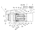
駐車ブレーキ付きディスクブレーキ2は、図2に示すように、ディスクロータ20を挟んでその両側に配置された一対のインナ及びアウタブレーキパッド21、22と、該インナ及びアウタブレーキパッド21、22をディスクロータ20の両面に押圧させて制動力を発生するキャリパ23とを備えている。該駐車ブレーキ付きディスクブレーキ2は、キャリパ浮動型として構成されており、一対のインナ及びアウタブレーキパッド21、22及びキャリパ23は、車両の非回転部(例えば、ナックル等)に固定されたキャリア25にディスクロータ20の軸方向に移動可能に支持されている。
As shown in FIG. 2, the
キャリパ23は、キャリパ本体26とこのキャリパ本体26に内包されるピストン32とを有している。キャリパ本体26は、ディスクロータ20よりも車両内側に配置されるインナブレーキパッド21へ対向する基端側にシリンダ部27が形成され、ディスクロータ20よりも車両外側のアウタブレーキパッド22へ対向する先端側に爪部28が形成されている。シリンダ部27は、インナブレーキパッド21側となる一端が開口して、他端が底壁29を有する有底のシリンダ30が形成される。
The
シリンダ30内には、ピストンシール31を介してピストン32が摺動可能に設けられている。ピストン32は、内部が凹部33となったカップ形状となっており、外底部32aがインナブレーキパッド21と対向するようにシリンダ30内に収められている。また、外底部32aには、インナブレーキパッド21からディスクロータ軸方向に突出する突起部21aが係合する溝部32bが形成されている。この溝部32bがインナブレーキパッド21の突起部21aと係合することで、ピストン32がキャリパ本体26に対して相対回転しないように規制されている。ピストン32の凹部33には、後述する推進部材44が当接する内底部33aが設けられている。また、凹部33の内周面には、ピストン32と後述する推進部材44との相対回転を規制するための軸方向溝部33bが形成されている。
A
シリンダ30内におけるピストン32とシリンダ30の底壁29との間は、液圧室35として画成される。液圧室35には、マスタシリンダ13から液圧発生装置3を経由した液圧がシリンダ部27に設けられた流入口(図示略)から供給される。また、ピストン32の外側面とシリンダ30との間にはシリンダ30内への異物の侵入を防ぐダストブーツ36が介装されている。
A space between the
キャリパ本体26のシリンダ30の底部側には、シリンダ30の底壁29を挟んで電動駐車ブレーキ機構37が備えられている。該電動駐車ブレーキ機構37は、ピストン32を推進するピストン推進機構37Aと、電動モータ5を停止した状態で、推進したピストン32の位置を保持するピストン保持機構37Bとを有する。
An electric
ピストン推進機構37Aは、先端側に雄ねじ部を有して基端側に電動モータ5からの回転力を増力する減速機構(図示略)の回転力が伝達されるスピンドル41と、このスピンドル41に螺合される雌ねじ部を有してピストン32の凹部33内に配置される推進部材44とから構成されている。
The
スピンドル41は、シリンダ30の底壁29に設けた開口部40からシリンダ30内へ延びてシリンダ30内でシリンダ30の軸線上に配置されている。開口部40の内周面には、スピンドル41との間をシールするシール部材42が設けられている。このシール部材42は、シリンダ30内の液圧室35の液密性を維持する。スピンドル41は、シリンダ30の底壁29に配置したニードル軸受(スラスト軸受)43により回動可能に支持される。
The
推進部材44には、その外周部に径方向に突出する複数の突起部44aが設けられる。この突起部44aは、ピストン32の凹部33の内周面に設けた軸方向溝部33bにそれぞれ係合される。これにより、推進部材44は、ピストン32に対して回転不能となり、スピンドル41が回転することにより軸方向に移動自在、すなわち直動可能にピストン32に支持されて、ピストン32を推進することになる。推進部材44には、ピストン32の内底部33aに当接可能な当接部44bが形成されている。当接部44bは、略円錐形状に形成されてすり鉢状の内底部33aに当接してピストン32を推進するようになっている。当接部44bと内底部33aとの間は、電動駐車ブレーキ機構37の作動時以外の通常ブレーキ操作時や非ブレーキ操作時に、所定のクリアランス量をもって隙間が形成されることになっている。ここで、所定のクリアランス量は、駐車ブレーキのリリース作動時に推進部材44を所定位置まで後退させることで設定される。このときの推進部材44の後退量が大きすぎると、次の駐車ブレーキ作動時に時間を要してしまう。一方、推進部材44の後退量が小さすぎると、車両走行中のディスクロータ20の面振れによりインナブレーキパッド21を介してピストン32が後退しようとしても推進部材によりその後退が妨げられ、結果的にディスクロータとブレーキパッドが接触状態となる、いわゆる、引き摺りが発生してしまう。本実施形態においては、後述する制御によってピストン32と推進部材44とのクリアランス量を適正にしている。
The propelling
ピストン保持機構37Bは、スピンドル41と推進部材44との螺合部44Aにより構成されている。この螺合部44Aは、スピンドル41の回転力によって推進部材44が直動可能であるが、推進部材44に加わる軸力によってはスピンドル41が回転しない、いわゆる逆作動性が悪いものとなっている。したがって、駐車ブレーキによって停車状態を維持するため、ピストン推進機構37Aによって推進されたピストン32は、ピストン保持機構37Bである螺合部44Aによってそのピストン位置が保持されるようになっている。
The
なお、本実施形態においては、ピストン保持機構37Bを逆作動性が悪い螺合部44Aにより構成したが、これに限らず、駐車ブレーキの作動中には減速機構等のリリース方向への回転を規制すると共に、駐車ブレーキの解除時には電動モータ5のリリース方向への回転に伴って減速機構等のリリース方向への回転を許容する機構であれば、ラチェット機構やウォームギア等で構成してもよい。
In the present embodiment, the
駐車ブレーキ付きディスクブレーキ2が、通常ブレーキすなわちサービスブレーキとして用いられる場合には、以下のように作動する。運転者によりブレーキペダル11が操作されると、マスタシリンダ13から液圧が、液圧発生装置3及びシリンダ部27に設けられたポートを経由して駐車ブレーキ付きディスクブレーキ2のシリンダ30内の液圧室35に供給される。このとき、電動モータ5は停止した状態となっているので、スピンドル41に螺合された推進部材44が軸方向に移動することはなく、ピストン32は、液圧の上昇に伴ってピストンシール31を弾性変形させながら前進(ディスクロータ20に近づくほうへ移動)してインナブレーキパッド21をディスクロータ20に押圧する。このピストン32の押圧力の反力により、キャリパ本体26は、車両内側に移動して爪部28を介してアウタブレーキパッド22をディスクロータ20へ押圧することで液圧に応じた制動力が発生する。
When the
一方、ブレーキペダル11の操作が解除されると、駐車ブレーキ付きディスクブレーキ2の液圧室35の液圧は解放される。すると、ピストン32は、ピストンシール31の弾性復元力によりが後退し、これに応じて一対のインナ及びアウタブレーキパッド21、22がディスクロータ20から離間して、制動力が解除される。
On the other hand, when the operation of the
次に、駐車ブレーキ付きディスクブレーキ2は、駐車ブレーキとして用いられる場合には、以下のように作動する。駐車ブレーキで停車状態を保持する場合には、駐車ブレーキスイッチ7がアプライ側に操作される。すると、駐車ブレーキ制御装置4は、電動モータ5を駆動してスピンドル41をアプライ方向に回転させる。このスピンドル41のアプライ方向への回転により、推進部材44が直動(前進)してピストン32の凹部33の底部に当接し、ピストン32と推進部材44とが一体となって前進する。これにより、通常ブレーキ時と同様に制動力(停車状態保持力)が発生する。そして、駐車ブレーキ制御装置4は、所定の制動力が発生したときに電動モータ5を停止する。すると、駐車ブレーキ付きディスクブレーキ2は、ピストン保持機構37Bによりピストン32を所定の制動力が発生している状態に保持して、駐車ブレーキを作動状態とする。このとき、ピストン32に当接しているピストンシール31は、ピストン32の前進に伴って弾性変形するが、上述の通常ブレーキとは異なり、ピストンシール31に液圧が付加されないため、その弾性変形量は、通常ブレーキ時の弾性変形量に比べて小さいものとなっている。
Next, when used as a parking brake, the
一方、駐車ブレーキを解除する場合には、駐車ブレーキスイッチ7がリリース側に操作される。すると、駐車ブレーキ制御装置4は、電動モータ5をリリース方向に回転させる。駐車ブレーキ付きディスクブレーキ2は、ピストン保持機構37Bによるピストン32の保持が解除されると共に、スピンドル41がリリース方向に回転して推進部材44が後退していく。この推進部材44後退によりその後は、推進部材44が元の位置に戻ると同時に電動モータ5のリリース方向の回転が停止され、これにより駐車ブレーキが解除される。このとき、ピストン32はピストンシール31の弾性変形が復元する位置まで後退する。
On the other hand, when releasing the parking brake, the
この駐車ブレーキの解除時には、以下に示す、第1〜3実施形態のリリース制御が行われるようになっている。第1〜3実施形態の各制御フローのルーチンは、駐車ブレーキの解除の完了、すなわちリリース完了判定がされて、状態ステータスが非ロック状態となるまで行われるようになっている。 When the parking brake is released, the release control of the first to third embodiments described below is performed. The routine of each control flow of the first to third embodiments is performed until the completion of release of the parking brake, that is, the release completion determination is made and the state status becomes the unlocked state.
[第1実施形態]
ここで、駐車ブレーキを解除する際に適切なピストン32と推進部材44とのクリアランス量を得るための駐車ブレーキ制御装置4における第1実施形態に係る制御フローを図3に基づいて詳細に説明する。なお、この制御フローは、駐車ブレーキ制御装置4の状態ステータスがロック状態となっているときに行われる。
[First Embodiment]
Here, a control flow according to the first embodiment in the parking
まず、ステップS1では、駐車ブレーキスイッチ7がリリース側に押されて駐車ブレーキのリリース作動(電動モータ5をリリース方向に回転させる)が開始するか否かが判定され、成立した場合には、電動モータ5をリリース方向に回転させる電流値が供給される。その後、ステップS2に進み、状態ステータスをリリース中とする。一方、ステップS1が不成立の場合にはルーチンを終了し、状態ステータスをロック状態のままとする。
ステップS2では、電動モータ5へ供給される電流値のモータ電流値検出手段6による計測が開始され、その後、電流値が所定の間隔で随時計測される。ステップS3では、計測されたモータ電流値から順次モータ回転速度の推定を開始する。これは、図4に示すモータ回転速度−モータ電流値(トルク)特性線図(N−T特性線図)に基づいてモータ回転速度を推定する。なお、上記N−T特性線図は、図4に示すように電動モータ5へ印加する電圧によって可変となっており、上記モータ回転速度を推定する際に、電動モータ5へ印加する電圧を駐車ブレーキ制御装置4によって測定する。そして、測定した電圧に応じたN−T特性線図を選択し、選択したN−T特性線図からモータ回転速度を推定するようになっている。ここでは、モータ回転速度を推定する方法として、ブラシ付モータのモータを回転させたときに発生するブラシの電流リップルを監視してリップルを計測する等の手段も考えられる。
First, in step S1, it is determined whether or not the
In step S2, measurement by the motor current
ステップS4では、モータ電流値が閾値A1より大きくなったかを判定し、成立するまでこのステップS4の判定を継続し、成立した場合にはステップS5に進む。ステップS5では、モータ電流値が閾値A1以下になったかを判定し、成立するまでこのステップS5の判定を継続し、成立した場合にはステップS6に進む。ここで、図5のタイムチャートのモータ電流値Aとモータ位置Pとに示されているように、電動モータ5は、電流値を供給しても、すぐに回転せず、回転させるためにある程度の大きさ、すなわち閾値A1以上の電流値が必要となっている。そして、電動モータ5が回転し始めると、電流値は閾値A1以下に低下していくことになる。上記ステップS4,S5の処理によって、電動モータ5が回転し始めたことを検出している。また、上記閾値A1は、電動モータ5が回転し始めるための電流値よりも若干小さい値が実験的、または、電動モータの特性から設定されている。
In step S4, it is determined whether or not the motor current value is larger than the threshold value A1, and the determination in step S4 is continued until it is satisfied, and if it is satisfied, the process proceeds to step S5. In step S5, it is determined whether or not the motor current value is equal to or less than the threshold value A1, and the determination in step S5 is continued until it is satisfied, and if it is satisfied, the process proceeds to step S6. Here, as shown in the motor current value A and the motor position P in the time chart of FIG. 5, even if the
次に、ステップS6では、モータ電流値が閾値A2以下になったかを判定し、成立するまでこのステップS6の判定を継続し、成立した場合にはステップS7に進む。ここで、閾値A2は、上記閾値A1よりも小さく、一対のインナまたはアウタブレーキパッド21、22がディスクロータ20から離脱するときの電流値よりも若干大きな電流値が設定されている。上記ブレーキパッド21、22がディスクロータ20から離脱するときの電流値は、予め実験的に求められており、閾値A2は、誤差を含めて若干大きな電流値が設定されている。
ステップS7では、随時計測されたモータ電流値の微分値(変化量)の絶対値(以下、電流微分絶対値という)が所定値ΔA1以下、本実施形態においては、所定値ΔA1が0に設定されており、電流微分絶対値が0となったか否かが判定されて、成立するまでこのステップS7の判定を継続し、成立した場合にはステップS8に進む。このステップS6における判定結果が成立した時点で、一対のインナまたはアウタブレーキパッド21、22がディスクロータ20から離脱した(制動力が解除された)と判断する。ここで、電動モータ5がリリース方向に回転し続けて、一対のインナ及び/またはアウタブレーキパッド21、22がディスクロータ20から離脱すると、その回転はほぼ無負荷回転となる。このため、モータ電流値が無負荷電流値となり、電流微分絶対値は、0または0付近の状態が継続されるようになる。上記所定値ΔA1は、電動モータ5が無負荷回転となったこと検出するために0(誤差を踏まえて不感帯を設けてもよい)として設定されている。
Next, in step S6, it is determined whether or not the motor current value has become equal to or less than the threshold value A2, and the determination in step S6 is continued until it is satisfied, and if it is satisfied, the process proceeds to step S7. Here, the threshold value A2 is smaller than the threshold value A1 and is set to a current value slightly larger than the current value when the pair of inner or
In step S7, the absolute value (hereinafter referred to as current differential absolute value) of the differential value (change amount) of the motor current value measured at any time is set to a predetermined value ΔA1 or less, and in the present embodiment, the predetermined value ΔA1 is set to 0. It is then determined whether or not the absolute value of the current derivative has become 0. The determination in step S7 is continued until the absolute value is satisfied, and if it is satisfied, the process proceeds to step S8. When the determination result in step S6 is established, it is determined that the pair of inner or
次に、ステップS8では、電流微分絶対値が0(所定値△A1以下)に到達した時点から以降のモータ回転速度を積分してその積分値を計数する。そして、ステップS9では、ステップS8において計数したモータ回転速度の積分値が所定値X1を超えたか否かを判定し、成立するまでステップS8での計数とステップS9の判定とを継続する。ステップS9でモータ回転速度の積分値が所定値X1を超えて成立した場合には、ステップS10に進んで電動モータ5が停止され、その後、ステップS11でモータ回転速度の積分値をクリアする。これをもって、リリース完了が判定され、駐車ブレーキ制御装置4の状態ステータスは非ロック状態となる。ここで、上記所定値X1は、ピストン32のロールバック量以上となる距離を前記ピストンが移動するのに要する推力部材44の移動量に対応したモータ回転速度の積分値として設定されている。詳細には、通常ブレーキ時の液圧付加されたピストンシール31によるピストン32の所定のロールバック量と、インナ及びアウタブレーキパッド21、22が高温となったときに生じる熱膨張量の最大値と、車両走行時におけるディスクロータ20の面ブレ量の最大値とを考慮して、パッドの引き摺りが発生しないようなピストン32と推進部材44とのクリアランス量となるものとして設定されている。なお、積分値は、積分相当の値であればよく、例えば、時定数の大きなローパスフィルタを道いて計測してもよい。
Next, in step S8, the motor rotation speed is integrated after the current differential absolute value reaches 0 (predetermined value ΔA1 or less), and the integrated value is counted. In step S9, it is determined whether or not the integrated value of the motor rotation speed counted in step S8 has exceeded a predetermined value X1, and the count in step S8 and the determination in step S9 are continued until it is satisfied. If the integrated value of the motor rotational speed exceeds the predetermined value X1 in step S9, the process proceeds to step S10, where the
駐車ブレーキ制御装置4における第1実施形態に係る制御のタイムチャートを図5に基づいて上記した図4の制御フローチャートの各ステップに対応させて説明する。
A time chart of the control according to the first embodiment in the parking
(A)の時点では、電動モータ5は停止されており、(B)の時点で駐車ブレーキスイッチ7がリリース側に押される。すると、ステップS1の判断によって電動モータ5に対してリリース方向の電流が供給され始める。このとき、駐車ブレーキ制御装置4の制御状態を示す状態ステータスが、ロック状態からリリース中となる。
At the time (A), the
(B)時点から(D)時点にかけて、電動モータ5を回転させるためのトルクを大きくするため、モータ電流値が増加していく。このとき、電動モータ5は、回転していない状態であり、(D)時点で電動モータ5がリリース方向に回転し始めると、モータ電流値がピーク値となる。そして、電流値の上昇率を示すモータ電流微分値は、(B)時点から増加してピーク値を過ぎた後、急速に減少して(D)時点で0に近づく。この間で、ステップS4のモータ電流値が閾値A1より大きくなったか否かの判定が行われ、ステップS4が成立する(C)時点以降にステップS5のモータ電流値が閾値A1以下か否かの判定を開始している。
From time (B) to time (D), the motor current value increases in order to increase the torque for rotating the
(D)時点から(G)時点にかけて、電動モータ5は、ピストン32を介してブレーキ力の負荷を受けながらリリース方向へ回転する。電動モータ5がリリース方向へ回転するのに伴って徐々にブレーキ力の負荷が減少していくので、モータ電流値は(D)時点のピーク値から減少し始めて0に近づいていく。この間に、そして、このリリース中に上記ステップS5の判断条件であるモータ電流値が閾値A1以下となり、(E)時点で電動モータ5が回転し始めていることを判定する。
From time (D) to time (G), the
この後、さらに、上記ステップS6の判断条件であるモータ電流値が閾値A2以下となり、かつ、上記ステップS7の判断条件である電流微分絶対値が所定値以下となる(G)時点で一対のインナ及びアウタブレーキパッド21、22がディスクロータ20から離脱(制動力が抜けた)した状態となったものと判定する。なお、本実施の形態においては、確実にブレーキパッド21、22がディスクロータ20から離脱した状態を判定するために、ステップS6とステップS7との2つの判断条件を用いている。しかし、これに限らず、いずれか一方の判断条件で判定を行うようにしてもよい。すなわち、インナまたはアウタブレーキパッド21,22がディスクロータ20から離脱したと判断する条件として、ステップS6のリリース中にモータ電流値が閾値A2以下となった(F)時点としてもよい。また、ステップS6の判定を行わずに、ステップS7のみの電流微分絶対値が0(所定値ΔA1以下)となった時点としてもよい。また、駐車ブレーキ付きディスクブレーキ2に推力センサを設け、この推力センサを使用して制動力を監視し、インナおよびアウタブレーキパッド21,22がディスクロータ20を挟んで制動力が発生している(D)時点から離脱(制動力が抜けた)した(G)時点を検出するようにしてもよい。
Thereafter, when the motor current value, which is the determination condition in step S6, is less than or equal to the threshold A2, and the current differential absolute value, which is the determination condition in step S7, is less than or equal to a predetermined value (G), a pair of inner In addition, it is determined that the
(G)の時点からは、電動モータ5は、リリース方向に回転し続けるが、一対のインナ及びアウタブレーキパッド21、22がディスクロータ20から離脱しているので、その回転はほぼ無負荷回転となる。このため、モータ電流値が無負荷電流値となり、電流微分絶対値は、0付近の状態が継続される。このため、ステップS7で判定される(G)時点、すなわち、リリース中に電流微分絶対値が0(所定値ΔA1以下)となったときから、モータ回転速度の積分を開始(ステップS8)する。
From the point of time (G), the
リリース中に(G)時点から(H)時点にかけて、モータ回転速度を積分しておき、積分値(図5の斜線部(X))が、予め算出されたピストン32の所定のロールバック量以上に相当する所定値X1に到達したことがステップS9で判定されると、(H)の時点で電動モータ5が停止され(ステップS10)、駐車ブレーキのリリース完了となる。そして、駐車ブレーキ制御装置4の状態ステータスが、リリース中から非ロック状態となる。
During the release, the motor rotation speed is integrated from time (G) to time (H), and the integrated value (shaded portion (X) in FIG. 5) is equal to or greater than a predetermined rollback amount of the
このように、本実施の形態においては、ブレーキパッド21,22の少なくとも一方がディスクロータ20から離脱したことを検知してから、モータ回転速度の積分値が予め算出されたピストン32の所定のロールバック量以上に相当する所定値X1に到達したとき、電動モータ5が電流値に基づく所定量(モータ回転速度の積分値が所定値X1となる)分駆動したときに、電動モータ5を停止するようにしている。このため、駐車ブレーキのリリース動作の終了に伴うピストンと推進部材とのクリアランス量を適正にすることができる。これにより、駐車ブレーキ作動時の応答性が損なわれることなく、また、ブレーキ引き摺りを抑制することが可能となる。
As described above, in the present embodiment, after detecting that at least one of the
[第2実施形態]
次に、駐車ブレーキ制御装置4における第2実施形態に係る制御フローを図6に基づいて詳細に説明する。まず、ステップS11では、駐車ブレーキのリリース作動が開始されたか否かが判定され、成立した場合には、電動モータ5への電流供給を開始してステップS12に進み、不成立の場合にはルーチンが終了する。
ステップS12では、電動モータ5へ供給される電流値のモータ電流値検出手段6による計測が開始され、その後、電流値が所定の間隔で随時計測される。ステップS13では、随時計測されたモータ電流値の微分値が算出される。
[Second Embodiment]
Next, the control flow which concerns on 2nd Embodiment in the parking
In step S12, measurement of the current value supplied to the
次に、ステップS14では、電流微分絶対値が所定値ΔA2以下となったか否かが判定されて、成立した場合にはステップS15に進み、不成立の場合にはルーチンを終了する。ステップS15では、電流微分絶対値が所定値ΔA2以下に到達した時点からタイマカウントが開始される。ステップS16では、タイマカウンタが所定時間に到達したか否かが判定される。ここで、所定値ΔA2は、第1実施形態と同様に、ブレーキパッド21、22の少なくとも一方がディスクロータ20から離脱して電動モータ5が無負荷回転となったこと検出するため0よりも若干大きな値に設定されている。また、上記所定時間T1は、ピストン32のロールバック量以上となる距離を推進部材44が移動するのに要する時間として設定されている。詳細には、通常ブレーキ時の液圧付加されたピストンシール31によるピストン32の所定のロールバック量と、インナ及びアウタブレーキパッド21、22が高温となったときに生じる熱膨張量の最大値と、車両走行時におけるディスクロータ20の面ブレ量の最大値とを考慮して、パッドの引き摺りが発生しないようなピストン32と推進部材44とのクリアランス量となる推進部材44の移動時間として設定されている。
Next, in step S14, it is determined whether or not the current differential absolute value has become equal to or smaller than a predetermined value ΔA2. If satisfied, the process proceeds to step S15, and if not, the routine is terminated. In step S15, the timer count is started when the current differential absolute value reaches a predetermined value ΔA2 or less. In step S16, it is determined whether or not the timer counter has reached a predetermined time. Here, as in the first embodiment, the predetermined value ΔA2 is slightly smaller than 0 in order to detect that at least one of the
ステップS16の判定では、所定時間T1が制御周期よりも十分に大きな時間となっているため、すぐには成立とはならないので、不成立としてステップS17に進むことになる。ステップS17では、再度、電流微分絶対値が所定値ΔA2以下か否かが判定される。このステップS17が成立の場合には、ステップS16に戻って時間判定を行い、不成立、すなわち、電流微分絶対値が所定値ΔA2よりも大きくなっている場合には、ステップS18でタイマカウンタをクリアしてステップS14に戻る。ここで、再度、電流微分絶対値を判定するのは、リリースが開始されてから実際にブレーキパッド21、22がディスクロータ20から離脱するまで間、電流微分絶対値が所定値ΔA2以下となることが数回あり、この場合には、所定値ΔA2以下となっている時間が、所定時間T1よりも少ない時間となる。このため、ステップS16の判定に係る所定時間T1の間に、電流微分絶対値が所定値ΔA2よりも大きくなった場合には、時間の計数を中止して判定をやり直すようにしている。
In the determination in step S16, since the predetermined time T1 is sufficiently longer than the control period, it is not immediately established, and therefore, the process proceeds to step S17 as not established. In step S17, it is determined again whether or not the current differential absolute value is equal to or smaller than a predetermined value ΔA2. If step S17 is satisfied, the process returns to step S16 to make a time determination. If not satisfied, that is, if the current differential absolute value is larger than the predetermined value ΔA2, the timer counter is cleared in step S18. The process returns to step S14. Here, the reason why the current differential absolute value is determined again is that the current differential absolute value becomes equal to or less than the predetermined value ΔA2 until the
最終的に、ステップS16の判定が成立した場合には、ステップS19及びS20に進み、電動モータ5を停止して、タイマカウンタをクリアする。このステップS16における判定が成立した時点で、一対のインナ及びアウタブレーキパッド21、22がディスクロータ20から離脱してパッドの引き摺りが発生しないようなピストン32と推進部材44とのクリアランス量となる位置まで推進部材44が移動したと判断する。
Finally, if the determination in step S16 is established, the process proceeds to steps S19 and S20, the
次に、駐車ブレーキ制御装置4における第2実施形態に係る制御フローのタイムチャートを図7に基づいて説明する。なお、第2実施形態に係る制御フローのタイムチャートにおいて(A)時点〜(B)時点までは第1実施形態に係る制御のタイムチャートと同様のため、ここでの説明を省略する。
Next, a time chart of a control flow according to the second embodiment in the parking
(B)の時点において、電流微分絶対値が所定値ΔA2以下となるためステップS15の処理でタイマカウントが開始されるが、すぐに、電流微分絶対値が所定値ΔA2より大きくなるため、タイマカウントが終了してステップS14での電流微分絶対値の判定を継続する。 At the time of (B), the current differential absolute value becomes equal to or smaller than the predetermined value ΔA2, so that the timer count is started in the process of step S15, but immediately, the current differential absolute value becomes larger than the predetermined value ΔA2, so And the determination of the current differential absolute value in step S14 is continued.
次に、(C)の時点で、再び、電流微分絶対値が所定値ΔA2以下となるためステップS15の処理でタイマカウントが開始されるが、すぐに、(D)の時点で電流微分絶対値が所定値ΔA2より大きくなるため、タイマカウントが終了してステップS14での電流微分絶対値の判定を継続する。 Next, since the current differential absolute value becomes equal to or smaller than the predetermined value ΔA2 again at the time point (C), the timer count is started in the process of step S15, but immediately, the current differential absolute value at the time point (D). Becomes larger than the predetermined value ΔA2, the timer count ends, and the determination of the current differential absolute value in step S14 is continued.
最終的に、(E)の時点で電流微分絶対値が所定値ΔA2以下となるためステップS15の処理でタイマカウントが開始される。(E)の時点以降は、ブレーキパッド21、22がディスクロータ20から離脱して電動モータ5が無負荷回転となるので、ステップS16及びS17の処理で、タイマカウンタをカウントし続ける。(F)の時点において、ステップS16で所定時間T1を越えて、判定が成立することで、電動モータ5を停止が停止され(ステップS10)、駐車ブレーキのリリース完了となる。そして、駐車ブレーキ制御装置4の状態ステータスが、リリース中から非ロック状態となる。
Finally, since the current differential absolute value becomes equal to or smaller than the predetermined value ΔA2 at the time (E), the timer count is started in the process of step S15. After the time point (E), the
このように、本実施形態においては、電流微分絶対値に基づいてブレーキパッド21,22がディスクロータ20から離脱して、ピストン32のロールバック量以上となる距離を前記推進部材44が移動するのに要する所定時間T1に到達したとき、電動モータ5が電流値に基づく所定量(電流微分絶対値が閾値ΔA2となってから所定時間T1となる)分駆動したときに、電動モータ5を停止するようにしている。このため、駐車ブレーキのリリース動作の終了に伴うピストンと推進部材とのクリアランス量を適正にすることができる。これにより、駐車ブレーキ作動時の応答性が損なわれることなく、また、ブレーキ引き摺りを抑制することが可能となる。
As described above, in the present embodiment, the
[第3実施形態]
次に、駐車ブレーキ制御装置4における第3実施形態に係る制御フローを図8に基づいて詳細に説明する。まず、ステップS31では、駐車ブレーキのリリース作動が開始か否かが判定され、成立した場合には、電動モータ5へ電流を供給し、ステップS22に進み、不成立の場合にはルーチンが終了する。ステップS32では、電動モータ5へ供給される電流値のモータ電流値検出手段6による計測が開始され、その電流値が所定の間隔で随時計測される。ステップS33では、随時計測されたモータ電流値が下降傾向にあるか否かを、モータ電流値の微分値が正の値か負の値かで判定し、成立するまでこのステップS6の判定を継続する。モータ電流値が下降傾向にある場合は、上述したように、電動モータ5が回転し始めている状態となっているので、このステップS33では、電動モータ5が回転し始めているか否かが判定されることになる。ステップS33の判定が成立すると、ステップS34に進み、モータ電流値が閾値A3以下になったかを判定し、成立するまでこのステップS34の判定を継続する。ここで、閾値A3は、一対のインナ及びアウタブレーキパッド21、22がディスクロータ20から離脱するときの電流値が設定されている。上記ブレーキパッド21、22がディスクロータ20から離脱するときの電流値は、予め実験的に求められており、閾値A3は、誤差を考慮した電流値が設定されている。
[Third Embodiment]
Next, the control flow which concerns on 3rd Embodiment in the parking
次に、ステップS34の判定が成立すると、ステップS35に進み、ステップS35では、モータ電流値が閾値A3以下になった時点から以降のモータ電流値を積分してその積分値を計数する。そして、ステップS36では、ステップS35において計数したモータ電流値の積分値が所定値Y1を超えたか否かを判定し、成立するまでステップS35での計数とステップS36の判定とを継続する。ステップS36でモータ電流値の積分値が所定値Y1を超えて成立した場合には、ステップS37に進んで電動モータ5が停止され、その後、ステップS38でモータ電流値の積分値をクリアする。これをもって、リリース完了が判定され、駐車ブレーキ制御装置4の状態ステータスは非ロック状態となる。ここで、上記所定値Y1は、ピストン32のロールバック量以上となる距離を前記推進部材44が移動するのに要する推力部材44の移動量に対応したモータ電流値の積分値として設定されている。詳細には、通常ブレーキ時の液圧付加されたピストンシール31によるピストン32の所定のロールバック量と、インナ及びアウタブレーキパッド21、22が高温となったときに生じる熱膨張量の最大値と、車両走行時におけるディスクロータ20の面ブレ量の最大値とを考慮して、パッドの引き摺りが発生しないようなピストン32と推進部材44とのクリアランス量となるものとして設定されている。
Next, when the determination in step S34 is established, the process proceeds to step S35. In step S35, the subsequent motor current value is integrated from the time when the motor current value becomes equal to or less than the threshold value A3, and the integrated value is counted. In step S36, it is determined whether or not the integral value of the motor current value counted in step S35 has exceeded a predetermined value Y1, and the count in step S35 and the determination in step S36 are continued until the integration value is satisfied. If the integrated value of the motor current value exceeds the predetermined value Y1 in step S36, the process proceeds to step S37, where the
次に、駐車ブレーキ制御装置4における第3実施形態に係る制御フローのタイムチャートを図9に基づいて説明する。なお、第3実施形態に係る制御フローのタイムチャートにおいて(A)時点〜(B)までは第1及び2実施形態に係る制御フローのタイムチャートと同様のためここでの説明を省略する。
Next, a time chart of a control flow according to the third embodiment in the parking
(C)の時点において、モータ電流値の微分値が正の値となったときに、ステップS34の判定が成立して電動モータ5が回転し始めていることが判別される。そして、(D)の時点でモータ電流値が閾値A3以下になったときに、ステップS34の判定が成立してブレーキパッド21、22がディスクロータ20から離脱したことが判別される。
At the time of (C), when the differential value of the motor current value becomes a positive value, it is determined that the determination in step S34 is established and the
次に、(D)時点から(E)時点にかけて、ステップS35の処理でモータ電流値を積分して、該積分した値(図9の斜線部Y1)がピストン32の所定のロールバック量に相当する所定値Y1以上に到達したことがステップS36で判定されると、(E)の時点でステップS37及びS38の処理によって、電動モータ5が停止され、モータ電流値の積分値がクリアされて駐車ブレーキのリリース完了となる。そして、駐車ブレーキ制御装置4の状態ステータスが、リリース中から非ロック状態となる。
Next, from the time (D) to the time (E), the motor current value is integrated in the process of step S35, and the integrated value (shaded portion Y1 in FIG. 9) corresponds to the predetermined rollback amount of the
このように、本実施形態においては、モータ電流値に基づいてブレーキパッド21,22がディスクロータ20から離脱して、モータ電流値の積分値がピストン32のロールバック量以上となる距離を前記推進部材44が移動するのに要する所定値Y1に到達したとき、すなわち、電動モータ5が電流値に基づく所定量(モータ電流値の積分値が所定値Y1となる)分駆動したときに、電動モータ5を停止するようにしている。このため、駐車ブレーキのリリース動作の終了に伴うピストンと推進部材とのクリアランス量を適正にすることができる。これにより、駐車ブレーキ作動時の応答性が損なわれることなく、また、ブレーキ引き摺りを抑制することが可能となる。
As described above, in this embodiment, the
以上説明したように、上記実施形態に係るディスクブレーキ装置1では、リリース方向への電動モータ5の駆動に際して、インナ及びアウタブレーキパッド21、22と、ピストン32とのクリアランス量を過不足することなく最適なものにすることができる。また、モータ電流値により、駐車ブレーキのリリース動作時の最適な電動モータ5の駆動時間を設定できるので、外的な影響(例えば、機械的な構造上のバラツキや温度特性等)を受けることはない。
As described above, in the disc brake device 1 according to the above embodiment, when the
上述した各実施形態のディスクブレーキ装置は、ディスクの両面に配置されるブレーキパッドを液圧シリンダ内に設けられたピストンにより押圧するキャリパと、該キャリパに設けられ電動モータによりピストンを推進させる推進部材を有するピストン推進機構と、推進したピストンを保持するピストン保持機構と、前記電動モータの駆動を制御する制御手段と、を有し、前記制御手段は、前記ピストン保持機構によるピストンの保持を解除するべく前記電動モータを駆動した後に、前記ブレーキパッドが前記ディスクから離脱したことを検知してから、前記電動モータの電流値に基づく所定量分該電動モータを駆動したとき、該電動モータの駆動を停止するものとなっている。 The disk brake device of each embodiment described above includes a caliper that presses brake pads disposed on both sides of the disk by a piston provided in a hydraulic cylinder, and a propulsion member that is provided in the caliper and propels the piston by an electric motor. A piston propulsion mechanism, a piston holding mechanism for holding the propelled piston, and a control means for controlling the drive of the electric motor, wherein the control means releases the holding of the piston by the piston holding mechanism. Therefore, after driving the electric motor, when the electric motor is driven by a predetermined amount based on the current value of the electric motor after detecting that the brake pad is detached from the disk, the electric motor is driven. It is supposed to stop.
上記ディスクブレーキ装置によれば、駐車ブレーキのリリース動作の終了時点でのピストンと推進部材とのクリアランス量を適正にすることができる。 According to the disc brake device, the clearance amount between the piston and the propelling member at the end of the release operation of the parking brake can be made appropriate.
上述した第1、3実施形態のディスクブレーキ装置は、前記電動モータを駆動する所定量が、前記ブレーキパッドが前記ディスクから離脱したことの検知以降の前記電動モータの電流値に基づく検出値の積分値となっている。 In the disk brake device according to the first and third embodiments described above, the predetermined amount for driving the electric motor is an integration of the detection value based on the current value of the electric motor after the detection that the brake pad is detached from the disk. It is a value.
上記ディスクブレーキ装置によれば、電動モータの電流値に基づく検出値の積分値を計数するので、電動モータの位置や推進部材の位置を検出するための特別なセンサを設ける必要がなく、ディスクブレーキ装置の構造が複雑化せず、製造が容易となる。 According to the disc brake device, since the integral value of the detection value based on the current value of the electric motor is counted, there is no need to provide a special sensor for detecting the position of the electric motor or the position of the propulsion member. The structure of the apparatus is not complicated, and manufacturing is easy.
上述した第1、3実施形態のディスクブレーキ装置は、前記電動モータの電流値が、実電流値または電流指令値となっている。 In the disk brake devices of the first and third embodiments described above, the current value of the electric motor is an actual current value or a current command value.
上述した第1実施形態のディスクブレーキ装置は、前記検出値が、前記電動モータの回転速度となっている。 In the disc brake device of the first embodiment described above, the detected value is the rotational speed of the electric motor.
上述した第1実施形態のディスクブレーキ装置は、前記電動モータの回転速度が、前記電流値が前記電動モータへの印加電圧によって補正されて算出されるようになっている。 In the disk brake device according to the first embodiment described above, the rotational speed of the electric motor is calculated by correcting the current value by the voltage applied to the electric motor.
上述した第3実施形態のディスクブレーキ装置は、前記検出値が、電流値となっている。 In the disc brake device of the third embodiment described above, the detected value is a current value.
上述した各実施形態のディスクブレーキ装置は、前記所定値が、前記ブレーキパッドが前記ディスクから離脱してから前記ピストンのロールバック量以上となる距離を前記ピストンが移動するのに要する移動量に対応した値となっている。 In the disk brake device of each of the embodiments described above, the predetermined value corresponds to the movement amount required for the piston to move a distance that is equal to or greater than the rollback amount of the piston after the brake pad is detached from the disk. It is the value.
上述した第2実施形態のディスクブレーキ装置は、前記電動モータを駆動する所定量が、前記ブレーキパッドが前記ディスクから離脱してから前記ピストンのロールバック量以上となる距離を前記ピストンが移動するのに要する所定時間となっている。 In the disc brake device according to the second embodiment described above, the piston moves a distance where the predetermined amount for driving the electric motor is equal to or greater than the rollback amount of the piston after the brake pad is detached from the disc. It is a predetermined time required for.
上述した各実施形態のディスクブレーキ装置は、前記ブレーキパッドが前記ディスクから離脱したことが、前記電動モータの電流値が所定値以下となったことによって検知される。 In the disk brake device of each of the above-described embodiments, the release of the brake pad from the disk is detected when the current value of the electric motor becomes a predetermined value or less.
上記ディスクブレーキ装置によれば、ブレーキパッドがディスクから離脱したことを検出するための特別なセンサを設ける必要がなく、ディスクブレーキ装置の構造が複雑化せず、製造が容易となる。 According to the disc brake device, it is not necessary to provide a special sensor for detecting that the brake pad is detached from the disc, the structure of the disc brake device is not complicated, and the manufacture is facilitated.
上述した各実施形態のディスクブレーキ装置は、前記ブレーキパッドが前記ディスクから離脱したことは、前記電動モータの電流値が所定値以下となってから前記電動モータの電流値の微分値の絶対値が所定値以下となったことによって検知する。 In the disk brake device of each of the above-described embodiments, the fact that the brake pad is detached from the disk means that the absolute value of the differential value of the current value of the electric motor is less than a predetermined value after the current value of the electric motor becomes less than a predetermined value. It is detected when the value is below a predetermined value.
1 ディスクブレーキ装置,2 駐車ブレーキ付きディスクブレーキ,4 駐車ブレーキ制御装置,5 電動モータ,6 モータ電流値検出手段,7 駐車ブレーキスイッチ,20 ディスクロータ,21 インナブレーキパッド,22 アウタブレーキパッド,23 キャリパ,26 キャリパ本体,29 シリンダ部,30 シリンダ,32 ピストン,37 電動駐車ブレーキ機構,37A ピストン推進機構,37B ピストン保持機構,44 推進部材,44A 螺合部 DESCRIPTION OF SYMBOLS 1 Disc brake device, 2 Disc brake with parking brake, 4 Parking brake control device, 5 Electric motor, 6 Motor current value detection means, 7 Parking brake switch, 20 Disc rotor, 21 Inner brake pad, 22 Outer brake pad, 23 Caliper , 26 Caliper body, 29 cylinder part, 30 cylinder, 32 piston, 37 electric parking brake mechanism, 37A piston propulsion mechanism, 37B piston holding mechanism, 44 propulsion member, 44A screwing part
Claims (8)
該キャリパに設けられ電動モータによりピストンを推進させる推進部材を有するピストン推進機構と、
推進したピストンを保持するピストン保持機構と、
前記電動モータの駆動を制御する制御手段と、を有し、
前記制御手段は、前記ピストン保持機構によるピストンの保持を解除するべく前記電動モータを駆動した後に、前記ブレーキパッドが前記ディスクから離脱したことを検知してから、前記ブレーキパッドが前記ディスクから離脱したことの検知以降の前記電動モータの電流値に基づく検出値の積分値分該電動モータを駆動したとき、該電動モータの駆動を停止するディスクブレーキ装置。 A caliper that presses the brake pads arranged on both sides of the disc by a piston provided in the hydraulic cylinder;
A piston propulsion mechanism having a propulsion member provided in the caliper and propelling the piston by an electric motor;
A piston holding mechanism for holding the propelled piston;
Control means for controlling the drive of the electric motor,
The control means detects that the brake pad is detached from the disk after driving the electric motor to release the piston held by the piston holding mechanism, and then the brake pad is detached from the disk. A disc brake device that stops driving of the electric motor when the electric motor is driven by an integral value of a detection value based on a current value of the electric motor after the detection .
Priority Applications (5)
| Application Number | Priority Date | Filing Date | Title |
|---|---|---|---|
| JP2012081535A JP6017162B2 (en) | 2012-03-30 | 2012-03-30 | Disc brake device |
| US13/836,308 US8972140B2 (en) | 2012-03-30 | 2013-03-15 | Disc brake apparatus |
| CN201310219225.1A CN103362987B (en) | 2012-03-30 | 2013-03-22 | Disc brake apparatus |
| KR1020130030829A KR101990647B1 (en) | 2012-03-30 | 2013-03-22 | Disk brake device |
| DE102013205444.0A DE102013205444B4 (en) | 2012-03-30 | 2013-03-27 | Disc brake device |
Applications Claiming Priority (1)
| Application Number | Priority Date | Filing Date | Title |
|---|---|---|---|
| JP2012081535A JP6017162B2 (en) | 2012-03-30 | 2012-03-30 | Disc brake device |
Publications (3)
| Publication Number | Publication Date |
|---|---|
| JP2013209041A JP2013209041A (en) | 2013-10-10 |
| JP2013209041A5 JP2013209041A5 (en) | 2015-01-22 |
| JP6017162B2 true JP6017162B2 (en) | 2016-10-26 |
Family
ID=49154987
Family Applications (1)
| Application Number | Title | Priority Date | Filing Date |
|---|---|---|---|
| JP2012081535A Active JP6017162B2 (en) | 2012-03-30 | 2012-03-30 | Disc brake device |
Country Status (5)
| Country | Link |
|---|---|
| US (1) | US8972140B2 (en) |
| JP (1) | JP6017162B2 (en) |
| KR (1) | KR101990647B1 (en) |
| CN (1) | CN103362987B (en) |
| DE (1) | DE102013205444B4 (en) |
Cited By (1)
| Publication number | Priority date | Publication date | Assignee | Title |
|---|---|---|---|---|
| WO2021200459A1 (en) * | 2020-03-31 | 2021-10-07 | 日立Astemo株式会社 | Electric brake device and electric brake control device |
Families Citing this family (19)
| Publication number | Priority date | Publication date | Assignee | Title |
|---|---|---|---|---|
| DE102014202173A1 (en) * | 2014-02-06 | 2015-08-06 | Robert Bosch Gmbh | Method for releasing an automatic parking brake |
| JP6221118B2 (en) * | 2014-02-28 | 2017-11-01 | 日立オートモティブシステムズ株式会社 | Brake system |
| KR102114533B1 (en) | 2014-12-27 | 2020-06-26 | 히다치 오토모티브 시스템즈 가부시키가이샤 | Brake device |
| DE112015005833T5 (en) | 2014-12-27 | 2017-09-28 | Hitachi Automotive Systems, Ltd. | braking means |
| KR102321143B1 (en) * | 2015-04-13 | 2021-11-04 | 주식회사 만도 | Electronic parking brake system in a vehicle and method thereof |
| DE102015210431A1 (en) * | 2015-06-08 | 2016-12-08 | Robert Bosch Gmbh | Method for controlling a parking brake in a vehicle |
| US10137878B2 (en) * | 2015-10-14 | 2018-11-27 | Akebono Brake Industry Co., Ltd. | Method for controlling a parking brake system |
| JP2017082834A (en) * | 2015-10-23 | 2017-05-18 | 株式会社アドヴィックス | Brake for vehicle |
| US20180345433A1 (en) * | 2015-11-30 | 2018-12-06 | Hitachi Koki Co., Ltd. | Electrically powered tool |
| KR101676266B1 (en) | 2016-02-18 | 2016-11-16 | 이래오토모티브시스템 주식회사 | Detecting Apparatus and Detecting Method of Sensorless EPB Motor |
| KR101682667B1 (en) * | 2016-03-02 | 2016-12-12 | 이래오토모티브시스템 주식회사 | The Position Control System of the EPB Caliper and Cable Using the Actuator Current and Ripple |
| DE102016214219A1 (en) * | 2016-08-02 | 2018-02-08 | Robert Bosch Gmbh | Method for servicing a brake system with hydraulic vehicle brake and electromechanical brake device |
| DE102016223808A1 (en) * | 2016-11-30 | 2018-05-30 | Robert Bosch Gmbh | Method and device for operating a hydraulic brake system, brake system |
| DE102017201982A1 (en) * | 2017-02-08 | 2018-08-09 | Robert Bosch Gmbh | Brake motor control unit and brake system for a vehicle with an electric brake motor |
| DE102017209314A1 (en) * | 2017-06-01 | 2018-12-06 | Robert Bosch Gmbh | Method for operating a parking brake and control unit for operating a parking brake |
| KR101981479B1 (en) * | 2017-11-09 | 2019-05-23 | 현대모비스 주식회사 | Method and apparatus for detecting fault of electronic parking brake |
| KR102538538B1 (en) * | 2018-08-27 | 2023-06-01 | 에이치엘만도 주식회사 | Electric brake system and control method thereof |
| KR20220046718A (en) * | 2020-10-07 | 2022-04-15 | 현대모비스 주식회사 | Method for Controlling Electronic Parking Brake |
| US20220274575A1 (en) * | 2021-03-01 | 2022-09-01 | ZF Active Safety US Inc. | Hydraulic brake boost |
Family Cites Families (15)
| Publication number | Priority date | Publication date | Assignee | Title |
|---|---|---|---|---|
| KR20000048650A (en) * | 1996-10-03 | 2000-07-25 | 와다 아끼히로 | Braking system including motor-driven disc brake equipped with self-servo mechanism |
| DE19732168C2 (en) * | 1997-07-25 | 2003-06-18 | Lucas Ind Plc | Hydraulic vehicle brake with locking device and method for operating the same |
| JP4033281B2 (en) * | 2000-09-06 | 2008-01-16 | 日産自動車株式会社 | Braking device |
| JP2003083373A (en) | 2001-09-07 | 2003-03-19 | Akebono Brake Ind Co Ltd | Electric brake controlling method |
| JP4685491B2 (en) * | 2005-03-31 | 2011-05-18 | 日立オートモティブシステムズ株式会社 | Pedal device |
| DE102008018749A1 (en) * | 2007-09-12 | 2009-03-26 | Continental Teves Ag & Co. Ohg | Method for secure release of an electromechanically actuated parking brake |
| DE102008001990A1 (en) * | 2008-05-27 | 2009-12-03 | Robert Bosch Gmbh | Electric parking brake |
| KR20090130602A (en) * | 2008-06-16 | 2009-12-24 | 현대모비스 주식회사 | Caliper attaching typed electrical parking brake in vehicle |
| GB0817229D0 (en) * | 2008-09-19 | 2008-10-29 | Meritor Heavy Vehicle Braking | A control system and method for a parking brake mechanism |
| JP5320931B2 (en) * | 2008-09-24 | 2013-10-23 | 株式会社アドヴィックス | Parking brake control device |
| US8776958B2 (en) * | 2009-02-27 | 2014-07-15 | Toyota Jidosha Kabushiki Kaisha | Brake apparatus |
| DE102010029680B4 (en) * | 2009-06-16 | 2021-02-18 | Continental Teves Ag & Co. Ohg | Electromechanically actuated vehicle brake with a threaded spindle module |
| US8561762B2 (en) * | 2009-09-03 | 2013-10-22 | Honda Motor Co., Ltd. | Brake piston with steel core and phenolic outer layer |
| JP5333114B2 (en) * | 2009-09-18 | 2013-11-06 | 株式会社アドヴィックス | Parking brake control device |
| JP2012081535A (en) | 2010-10-08 | 2012-04-26 | Mimaki Engineering Co Ltd | Cutting program, cutting system, and cutting method |
-
2012
- 2012-03-30 JP JP2012081535A patent/JP6017162B2/en active Active
-
2013
- 2013-03-15 US US13/836,308 patent/US8972140B2/en active Active
- 2013-03-22 CN CN201310219225.1A patent/CN103362987B/en active Active
- 2013-03-22 KR KR1020130030829A patent/KR101990647B1/en active IP Right Grant
- 2013-03-27 DE DE102013205444.0A patent/DE102013205444B4/en active Active
Cited By (3)
| Publication number | Priority date | Publication date | Assignee | Title |
|---|---|---|---|---|
| WO2021200459A1 (en) * | 2020-03-31 | 2021-10-07 | 日立Astemo株式会社 | Electric brake device and electric brake control device |
| DE112021002077T5 (en) | 2020-03-31 | 2023-03-09 | Hitachi Astemo, Ltd. | Electric braking device and electric braking control device |
| JP7411783B2 (en) | 2020-03-31 | 2024-01-11 | 日立Astemo株式会社 | Electric brake equipment and electric brake control equipment |
Also Published As
| Publication number | Publication date |
|---|---|
| KR101990647B1 (en) | 2019-06-18 |
| KR20130111338A (en) | 2013-10-10 |
| US8972140B2 (en) | 2015-03-03 |
| CN103362987A (en) | 2013-10-23 |
| JP2013209041A (en) | 2013-10-10 |
| DE102013205444B4 (en) | 2021-02-25 |
| DE102013205444A1 (en) | 2013-10-02 |
| US20130261917A1 (en) | 2013-10-03 |
| CN103362987B (en) | 2016-12-28 |
Similar Documents
| Publication | Publication Date | Title |
|---|---|---|
| JP6017162B2 (en) | Disc brake device | |
| JP5898035B2 (en) | Disc brake device | |
| US9475472B2 (en) | Brake system | |
| JP6129553B2 (en) | Brake system | |
| KR102116169B1 (en) | Brake device | |
| US20130275019A1 (en) | Electric parking brake control device | |
| JP5234266B2 (en) | Disc brake device | |
| JP2018086868A (en) | Electric-brake control device | |
| JP6457260B2 (en) | Brake device | |
| US10611350B2 (en) | Electric brake device | |
| JP2009073475A (en) | Disk brake apparatus | |
| US20160297410A1 (en) | Electronic parking brake system in vehicle and control method thereof | |
| JP2002213507A (en) | Electric brake device | |
| JP6205821B2 (en) | Electric parking brake control device | |
| JP6900881B2 (en) | Electric brake control device | |
| JP6478617B2 (en) | Brake device | |
| JP6490450B2 (en) | Brake device | |
| JP5998636B2 (en) | Brake device for vehicle | |
| JP6189144B2 (en) | Electric brake system | |
| JP5962279B2 (en) | Brake device for vehicle | |
| JP4482843B2 (en) | Electric disc brake pad wear detection method and electric disc brake device | |
| JP2016222097A (en) | Electric parking brake | |
| JP2020026240A (en) | Brake system for vehicle | |
| JP6011094B2 (en) | Parking brake control device | |
| JP6366035B2 (en) | Brake device |
Legal Events
| Date | Code | Title | Description |
|---|---|---|---|
| A521 | Request for written amendment filed |
Free format text: JAPANESE INTERMEDIATE CODE: A523 Effective date: 20141202 |
|
| A621 | Written request for application examination |
Free format text: JAPANESE INTERMEDIATE CODE: A621 Effective date: 20141202 |
|
| A131 | Notification of reasons for refusal |
Free format text: JAPANESE INTERMEDIATE CODE: A131 Effective date: 20150924 |
|
| A977 | Report on retrieval |
Free format text: JAPANESE INTERMEDIATE CODE: A971007 Effective date: 20150928 |
|
| A131 | Notification of reasons for refusal |
Free format text: JAPANESE INTERMEDIATE CODE: A131 Effective date: 20160511 |
|
| A521 | Request for written amendment filed |
Free format text: JAPANESE INTERMEDIATE CODE: A523 Effective date: 20160616 |
|
| TRDD | Decision of grant or rejection written | ||
| A01 | Written decision to grant a patent or to grant a registration (utility model) |
Free format text: JAPANESE INTERMEDIATE CODE: A01 Effective date: 20160831 |
|
| A61 | First payment of annual fees (during grant procedure) |
Free format text: JAPANESE INTERMEDIATE CODE: A61 Effective date: 20160928 |
|
| R150 | Certificate of patent or registration of utility model |
Ref document number: 6017162 Country of ref document: JP Free format text: JAPANESE INTERMEDIATE CODE: R150 |
|
| S533 | Written request for registration of change of name |
Free format text: JAPANESE INTERMEDIATE CODE: R313533 |
|
| R350 | Written notification of registration of transfer |
Free format text: JAPANESE INTERMEDIATE CODE: R350 |
|
| R250 | Receipt of annual fees |
Free format text: JAPANESE INTERMEDIATE CODE: R250 |
|
| R250 | Receipt of annual fees |
Free format text: JAPANESE INTERMEDIATE CODE: R250 |
|
| R250 | Receipt of annual fees |
Free format text: JAPANESE INTERMEDIATE CODE: R250 |