JP6012732B2 - Metering system for liquid reducing agents - Google Patents
Metering system for liquid reducing agents Download PDFInfo
- Publication number
- JP6012732B2 JP6012732B2 JP2014526428A JP2014526428A JP6012732B2 JP 6012732 B2 JP6012732 B2 JP 6012732B2 JP 2014526428 A JP2014526428 A JP 2014526428A JP 2014526428 A JP2014526428 A JP 2014526428A JP 6012732 B2 JP6012732 B2 JP 6012732B2
- Authority
- JP
- Japan
- Prior art keywords
- pump
- ventilation
- diaphragm
- metering system
- valve
- Prior art date
- Legal status (The legal status is an assumption and is not a legal conclusion. Google has not performed a legal analysis and makes no representation as to the accuracy of the status listed.)
- Active
Links
Images


Classifications
-
- F—MECHANICAL ENGINEERING; LIGHTING; HEATING; WEAPONS; BLASTING
- F04—POSITIVE - DISPLACEMENT MACHINES FOR LIQUIDS; PUMPS FOR LIQUIDS OR ELASTIC FLUIDS
- F04B—POSITIVE-DISPLACEMENT MACHINES FOR LIQUIDS; PUMPS
- F04B23/00—Pumping installations or systems
- F04B23/04—Combinations of two or more pumps
- F04B23/08—Combinations of two or more pumps the pumps being of different types
- F04B23/12—Combinations of two or more pumps the pumps being of different types at least one pump being of the rotary-piston positive-displacement type
-
- F—MECHANICAL ENGINEERING; LIGHTING; HEATING; WEAPONS; BLASTING
- F01—MACHINES OR ENGINES IN GENERAL; ENGINE PLANTS IN GENERAL; STEAM ENGINES
- F01N—GAS-FLOW SILENCERS OR EXHAUST APPARATUS FOR MACHINES OR ENGINES IN GENERAL; GAS-FLOW SILENCERS OR EXHAUST APPARATUS FOR INTERNAL COMBUSTION ENGINES
- F01N3/00—Exhaust or silencing apparatus having means for purifying, rendering innocuous, or otherwise treating exhaust
- F01N3/08—Exhaust or silencing apparatus having means for purifying, rendering innocuous, or otherwise treating exhaust for rendering innocuous
- F01N3/10—Exhaust or silencing apparatus having means for purifying, rendering innocuous, or otherwise treating exhaust for rendering innocuous by thermal or catalytic conversion of noxious components of exhaust
- F01N3/18—Exhaust or silencing apparatus having means for purifying, rendering innocuous, or otherwise treating exhaust for rendering innocuous by thermal or catalytic conversion of noxious components of exhaust characterised by methods of operation; Control
- F01N3/20—Exhaust or silencing apparatus having means for purifying, rendering innocuous, or otherwise treating exhaust for rendering innocuous by thermal or catalytic conversion of noxious components of exhaust characterised by methods of operation; Control specially adapted for catalytic conversion ; Methods of operation or control of catalytic converters
- F01N3/2066—Selective catalytic reduction [SCR]
- F01N3/208—Control of selective catalytic reduction [SCR], e.g. dosing of reducing agent
-
- F—MECHANICAL ENGINEERING; LIGHTING; HEATING; WEAPONS; BLASTING
- F01—MACHINES OR ENGINES IN GENERAL; ENGINE PLANTS IN GENERAL; STEAM ENGINES
- F01N—GAS-FLOW SILENCERS OR EXHAUST APPARATUS FOR MACHINES OR ENGINES IN GENERAL; GAS-FLOW SILENCERS OR EXHAUST APPARATUS FOR INTERNAL COMBUSTION ENGINES
- F01N3/00—Exhaust or silencing apparatus having means for purifying, rendering innocuous, or otherwise treating exhaust
- F01N3/08—Exhaust or silencing apparatus having means for purifying, rendering innocuous, or otherwise treating exhaust for rendering innocuous
- F01N3/10—Exhaust or silencing apparatus having means for purifying, rendering innocuous, or otherwise treating exhaust for rendering innocuous by thermal or catalytic conversion of noxious components of exhaust
- F01N3/24—Exhaust or silencing apparatus having means for purifying, rendering innocuous, or otherwise treating exhaust for rendering innocuous by thermal or catalytic conversion of noxious components of exhaust characterised by constructional aspects of converting apparatus
-
- F—MECHANICAL ENGINEERING; LIGHTING; HEATING; WEAPONS; BLASTING
- F01—MACHINES OR ENGINES IN GENERAL; ENGINE PLANTS IN GENERAL; STEAM ENGINES
- F01N—GAS-FLOW SILENCERS OR EXHAUST APPARATUS FOR MACHINES OR ENGINES IN GENERAL; GAS-FLOW SILENCERS OR EXHAUST APPARATUS FOR INTERNAL COMBUSTION ENGINES
- F01N2610/00—Adding substances to exhaust gases
- F01N2610/02—Adding substances to exhaust gases the substance being ammonia or urea
-
- F—MECHANICAL ENGINEERING; LIGHTING; HEATING; WEAPONS; BLASTING
- F01—MACHINES OR ENGINES IN GENERAL; ENGINE PLANTS IN GENERAL; STEAM ENGINES
- F01N—GAS-FLOW SILENCERS OR EXHAUST APPARATUS FOR MACHINES OR ENGINES IN GENERAL; GAS-FLOW SILENCERS OR EXHAUST APPARATUS FOR INTERNAL COMBUSTION ENGINES
- F01N2610/00—Adding substances to exhaust gases
- F01N2610/14—Arrangements for the supply of substances, e.g. conduits
- F01N2610/1433—Pumps
-
- F—MECHANICAL ENGINEERING; LIGHTING; HEATING; WEAPONS; BLASTING
- F01—MACHINES OR ENGINES IN GENERAL; ENGINE PLANTS IN GENERAL; STEAM ENGINES
- F01N—GAS-FLOW SILENCERS OR EXHAUST APPARATUS FOR MACHINES OR ENGINES IN GENERAL; GAS-FLOW SILENCERS OR EXHAUST APPARATUS FOR INTERNAL COMBUSTION ENGINES
- F01N2610/00—Adding substances to exhaust gases
- F01N2610/14—Arrangements for the supply of substances, e.g. conduits
- F01N2610/1466—Means for venting air out of conduits or tanks
-
- F—MECHANICAL ENGINEERING; LIGHTING; HEATING; WEAPONS; BLASTING
- F01—MACHINES OR ENGINES IN GENERAL; ENGINE PLANTS IN GENERAL; STEAM ENGINES
- F01N—GAS-FLOW SILENCERS OR EXHAUST APPARATUS FOR MACHINES OR ENGINES IN GENERAL; GAS-FLOW SILENCERS OR EXHAUST APPARATUS FOR INTERNAL COMBUSTION ENGINES
- F01N2610/00—Adding substances to exhaust gases
- F01N2610/14—Arrangements for the supply of substances, e.g. conduits
- F01N2610/1473—Overflow or return means for the substances, e.g. conduits or valves for the return path
-
- F—MECHANICAL ENGINEERING; LIGHTING; HEATING; WEAPONS; BLASTING
- F01—MACHINES OR ENGINES IN GENERAL; ENGINE PLANTS IN GENERAL; STEAM ENGINES
- F01N—GAS-FLOW SILENCERS OR EXHAUST APPARATUS FOR MACHINES OR ENGINES IN GENERAL; GAS-FLOW SILENCERS OR EXHAUST APPARATUS FOR INTERNAL COMBUSTION ENGINES
- F01N2610/00—Adding substances to exhaust gases
- F01N2610/14—Arrangements for the supply of substances, e.g. conduits
- F01N2610/1493—Purging the reducing agent out of the conduits or nozzle
-
- F—MECHANICAL ENGINEERING; LIGHTING; HEATING; WEAPONS; BLASTING
- F04—POSITIVE - DISPLACEMENT MACHINES FOR LIQUIDS; PUMPS FOR LIQUIDS OR ELASTIC FLUIDS
- F04B—POSITIVE-DISPLACEMENT MACHINES FOR LIQUIDS; PUMPS
- F04B23/00—Pumping installations or systems
- F04B23/04—Combinations of two or more pumps
- F04B23/08—Combinations of two or more pumps the pumps being of different types
- F04B23/10—Combinations of two or more pumps the pumps being of different types at least one pump being of the reciprocating positive-displacement type
Description
ディーゼル方式に基づいて作動する内燃機関では、環境に関わる責務を果たすために、SCR触媒装置が排ガス設備にしばしば設けられる。排ガス中に含まれるNOx化合物をSCR触媒装置が水と大気窒素に変換できるようにするために、SCR触媒装置の上流側では、液体尿素または液体の尿素水溶液(還元剤)が排ガス系統に噴射されなければならない。この目的のために、タンクと、ポンプと、燃料噴射設備のインジェクタに似た働きをする調量モジュールとを含む調量システムが利用される。このポンプは送出モジュールとも呼ばれる。 In an internal combustion engine that operates on the basis of a diesel system, an SCR catalyst device is often provided in an exhaust gas facility in order to fulfill its environmental responsibilities. In order to enable the SCR catalyst device to convert NOx compounds contained in the exhaust gas into water and atmospheric nitrogen, liquid urea or a liquid urea aqueous solution (reducing agent) is injected into the exhaust gas system upstream of the SCR catalyst device. There must be. For this purpose, a metering system is used which includes a tank, a pump and a metering module which acts like an injector of a fuel injection facility. This pump is also called the delivery module.
送出モジュールないしポンプの役割は、尿素水溶液をタンクから吸い出して、圧力側で十分な圧力を生成し、それにより、調量モジュールが必要に応じて制御されて開くとただちに、液体の尿素水溶液が細かく噴霧化されるようにすることにある。インジェクタも送出モジュールと同様に内燃機関の制御装置と接続されており、これによって必要に応じて開かれ、再び閉じられる。同様のことは送出ポンプの作動についても当てはまる。尿素水溶液は温度が低いと凍結し、その際に容積がおよそ11%増えるという特性があるので、凍った尿素水溶液による調量システムの損傷を防止するための方策を講じなければならない。 The function of the delivery module or pump is to suck out the aqueous urea solution from the tank and generate sufficient pressure on the pressure side, so that the liquid urea aqueous solution becomes finer as soon as the metering module is controlled and opened as required. It is to be atomized. The injector is connected to the control device of the internal combustion engine in the same manner as the delivery module, so that it is opened and closed again as necessary. The same applies to the operation of the delivery pump. The urea aqueous solution has a characteristic that it freezes when the temperature is low and the volume increases by about 11% at that time. Therefore, measures must be taken to prevent damage to the metering system due to the frozen urea aqueous solution .
この目的のために特許文献1より、尿素水溶液を通す配管を換気することが知られている。そのために、ポンプは逆転可能な送出方向を有するように構成されており、ないしは、ポンプの送出方向を逆転させるためのバルブが設けられる。 For this purpose, it is known from Patent Document 1 to ventilate a pipe through which an aqueous urea solution is passed. For this purpose, the pump is configured to have a reversible delivery direction, or a valve for reversing the pump delivery direction is provided.
特許文献2より、調量システムに4/2ウェイバルブを組み込むことが知られている。4/2ウェイバルブが第1の切換位置にあるとき、ポンプは還元剤をタンクから調量モジュールへ送出する。内燃機関を停止させることが意図されるとき、4/2ウェイバルブが第2の切換位置へと移され、それにより、送出モジュールのポンプが液体還元剤を調量モジュールからタンクへと送出し、それによって調量システムの数箇所部分を換気する。そのためには、調量モジュールが開いており、空気ないし排ガスが排ガス系統から調量システムへ追加流入できることが前提条件となる。
From
調量システムの部分的な換気によって圧縮気泡が発生し、それにより、残っている残留の還元剤が調量システムで凍ったとき、その結果として生じる氷圧は、調量システムに損害が生じない程度に低くなる。しかし、このような4/2ウェイバルブは故障が起こりやすく高価である。 When the metering system is partially ventilated, compressed bubbles are generated, so that when the remaining reducing agent is frozen in the metering system, the resulting ice pressure does not damage the metering system. Low. However, such 4 / 2-way valves are prone to failure and are expensive.
請求項1に記載された本発明による調量システムは、非常に低コストであるとともに、内燃機関の停止後の調量システムの確実な水抜きないし換気を保証するという特徴がある。本発明による換気ポンプは、調量システムを換気ないし水抜きする役目を果たすだけなので、非常に低い送出能力があれば足りる。換気ポンプの送出圧力に関しても低い要求事項しか課せられない。その帰結として、本発明による換気ポンプは4/2ウェイバルブよりも低コストである。さらに、このようなポンプは切換可能な4/2ウェイバルブよりも故障の起こりやすさが低い。 The metering system according to the invention as claimed in claim 1 is characterized by a very low cost and guaranteeing reliable drainage or ventilation of the metering system after the internal combustion engine is stopped. The ventilation pump according to the invention only serves to ventilate or drain the metering system, so a very low delivery capacity is sufficient. Only low requirements are imposed on the delivery pressure of the ventilation pump. As a consequence, the ventilation pump according to the invention is less expensive than a 4/2 way valve. Furthermore, such pumps are less prone to failure than switchable 4 / 2-way valves.
本発明による送出ポンプおよび/または本発明による換気ポンプは、ダイヤフラムポンプとして構成されているのが好ましい。しかしながら本発明は、ダイヤフラムポンプだけに限定されるものではない。従来技術から知られているこれ以外の型式を採用することもできる。 The delivery pump according to the invention and / or the ventilation pump according to the invention is preferably configured as a diaphragm pump. However, the present invention is not limited only to the diaphragm pump. Other models known from the prior art can also be employed.
本発明による送出ポンプおよび/または換気ポンプが、往復式ソレノイドとも呼ばれる電磁式の(リニア)アクチュエータにより駆動されると特別に好ましいことが判明している。すなわちその場合、たとえば電動モータの回転運動を、振動性のポンプの送出運動に変換するのを省略することができる。 It has been found that the delivery pump and / or the ventilation pump according to the invention are particularly preferred when driven by an electromagnetic (linear) actuator, also called a reciprocating solenoid. That is, in that case, it is possible to omit, for example, converting the rotational motion of the electric motor into the delivery motion of the vibratory pump.
電磁式のアクチュエータを介してのダイヤフラムポンプのダイレクトドライブは、アクチュエータのストロークを通じて、噴射される還元剤の量を非常に正確に検出することを簡単かつ低コストな仕方で可能にする。 The direct drive of the diaphragm pump via an electromagnetic actuator makes it possible to detect the amount of reducing agent injected very accurately and in a simple and cost-effective manner through the stroke of the actuator.
たとえば電磁式のアクチュエータを通る電機子電流の推移から、アクチュエータのストロークを推測することができる。アクチュエータのストロークは、送出された還元剤の量を表す直接的な目安である。したがって、本発明による調量システムの測定精度を低下させることなく、別個の圧力センサを省略することが可能である。 For example, the stroke of the actuator can be estimated from the transition of the armature current passing through the electromagnetic actuator. The actuator stroke is a direct measure of the amount of reducing agent delivered. It is therefore possible to dispense with a separate pressure sensor without reducing the measurement accuracy of the metering system according to the invention.
送出ポンプおよび/または換気ポンプの機能を最適化するために、これら両方のポンプの吸込側および/または送出側にはそれぞれ逆止め弁が設けられている。別案として、送出ポンプおよび/または換気ポンプの吸込側および/または送出側にそれぞれスロットルまたは絞りが設けられていることも可能である。多くの利用ケースにおいて、吸込側にも送出側にもそれぞれ逆止め弁が設けられていると好ましい。別案として、吸込側または送出側のいずれかにスロットルないし絞りを設け、圧力側または吸込側に逆止め弁を設けることも可能である。 In order to optimize the function of the delivery pump and / or the ventilation pump, a check valve is provided on the suction side and / or delivery side of both pumps. Alternatively, a throttle or throttling can be provided on the suction side and / or the delivery side of the delivery pump and / or the ventilation pump, respectively. In many use cases, it is preferable that a check valve is provided on each of the suction side and the delivery side. As an alternative, it is also possible to provide a throttle or throttle on either the suction side or the delivery side and a check valve on the pressure side or the suction side.
本発明による調量システムの好ましい実施形態では、換気ポンプの吸込側では第1の逆止め弁と並列に第2の逆止め弁が設けられており、第2の逆止め弁の阻止方向は第1の逆止め弁の阻止方向と反対を向いている。 In a preferred embodiment of the metering system according to the invention, a second check valve is provided in parallel with the first check valve on the suction side of the ventilation pump, the blocking direction of the second check valve being the first. It faces away from the check direction of 1 check valve.
それにより、本発明による換気ポンプを圧力補償部材として利用することが可能である。すなわち、送出ポンプ作動時に圧力配管で許容されない高い圧力が生じると、その結果として調量モジュールや圧力配管に損傷が生じる恐れがある。 Thereby, the ventilation pump according to the present invention can be used as a pressure compensation member. That is, if a high pressure that is unacceptable in the pressure piping is generated when the delivery pump is operated, the metering module and the pressure piping may be damaged as a result.
本発明による調量システムでは、送出ポンプの作動時に換気ポンプが圧力補償部材として利用される。すなわち、換気ポンプの吸込側にある第1の逆止め弁が開くほど高い圧力が圧力配管に生じると、圧力配管に由来する高い圧力が、換気ポンプのダイヤフラムに対して作用する。このダイヤフラムは、電気式のアクチュエータの方向に伸長することによって、こうした圧力を撓んで受け止めることができる。それにより、本発明による調量システムの圧力側で容積が増大し、圧力ピークが低減される。 In the metering system according to the invention, a ventilation pump is used as a pressure compensation member when the delivery pump is activated. That is, when a pressure that is high enough to open the first check valve on the suction side of the ventilation pump is generated in the pressure pipe, the high pressure derived from the pressure pipe acts on the diaphragm of the ventilation pump. The diaphragm can bend and receive such pressure by extending in the direction of the electric actuator. Thereby, the volume increases on the pressure side of the metering system according to the invention and the pressure peak is reduced.
別案として、許容されない高い圧力が圧力配管で発生したときに開き、そのようにして、送出ポンプから送出される尿素水溶液の一部が圧力配管から吸込配管へ流れ戻るように、換気配管における圧力側の逆止め弁を構成することも可能である。それにより、同じく効果的な圧力制限が実現される。そのためにも追加のコストは必要ない。 As an alternative, the pressure in the ventilation pipe opens so that an unacceptably high pressure occurs in the pressure pipe, so that part of the urea aqueous solution delivered from the delivery pump flows back from the pressure pipe to the suction pipe. It is also possible to construct a side check valve. Thereby, the same effective pressure limitation is realized. For this purpose, no additional cost is required.
当然のことながら、両方の態様すなわち換気ポンプのダイヤフラムの弾性変形と、換気配管の開放との組み合わせも実現可能である。 Of course, a combination of both aspects, namely the elastic deformation of the diaphragm of the ventilation pump and the opening of the ventilation pipes is also feasible.
本発明の別の好ましい実施形態では、換気ポンプの圧力側で逆止め弁と並列にスロットルまたは絞りが設けられていることが意図される。これらによって、電気式のアクチュエータを小型に設計することができる。それによって電気的な消費電力が少なくなり、さらには所要の重量や設計スペースも減る。 In another preferred embodiment of the invention, it is contemplated that a throttle or throttle is provided in parallel with the check valve on the pressure side of the ventilation pump. Thus, the electric actuator can be designed in a small size. This reduces the electrical power consumption and also reduces the required weight and design space.
本発明の特別に好ましい実施形態は、ダイヤフラムポンプにおいて、アクチュエータが無通電のとき、ダイヤフラムが換気ポンプの圧力側または吸込側で換気配管を閉止することを意図している。それにより本発明の換気ポンプは、コンポーネントに関わる追加のコストを要することなく、切換可能な方向制御弁の機能を果たす。それが可能である理由は、ダイヤフラムが還元剤を送出室から換気配管へ押し出すときの送出作業が、ダイヤフラムに作用するばねによって行われるからである。このばねは電磁式のアクチュエータにより、送出ポンプの吸込ストロークのときに初期応力をかけられる。 A particularly preferred embodiment of the invention contemplates that in a diaphragm pump, when the actuator is de-energized, the diaphragm closes the ventilation piping on the pressure side or suction side of the ventilation pump. Thereby, the ventilation pump of the present invention performs the function of a switchable directional control valve without the additional costs associated with the components. This is possible because the delivery operation when the diaphragm pushes the reducing agent from the delivery chamber to the ventilation pipe is performed by a spring acting on the diaphragm. This spring is subjected to an initial stress by an electromagnetic actuator during the suction stroke of the delivery pump.
したがって、適当な設計上の構成により、ダイヤフラムがばねによってポンプハウジングの換気配管の接続部に押圧され、そのようにしてこれを閉止することが容易に可能である。 Thus, with an appropriate design configuration, the diaphragm can be easily pressed against the connection of the ventilation pipe of the pump housing by a spring and thus can be easily closed.
密閉作用を高めるために、ないしは、換気ポンプのダイヤフラムが換気配管を遮断することができる送出室の最大圧力を高めるために、ハウジングに断面狭隘部を設けることができる。この断面狭隘部は、同時に、スロットルまたは絞りとして構成されていてよい。 In order to increase the sealing action, or to increase the maximum pressure in the delivery chamber where the diaphragm of the ventilation pump can block the ventilation piping, the housing can be provided with a narrow section. This narrowed section may be configured as a throttle or a throttle at the same time.
さらに、圧力配管または吸込配管の端部を取り囲む環状の隆起部が構成されることによって、ダイヤフラムの密閉性ないし最大の保持圧力/閉止圧力を高めることが可能である。それにより、隆起部とダイヤフラムとの間でいっそう高い単位面積あたり押圧力が生じ、その結果、制御可能な方向制御弁として利用されるダイヤフラムポンプの密閉性も高くなる。この場合にも、追加の隆起部に要するコストは無視することができる。ポンプのハウジングはごく一般的にプラスチック射出成形部品として、または鋳造された金属部品として製作され、したがって隆起部のために追加の製造費用が発生しないからである。 Further, by forming an annular ridge that surrounds the end of the pressure pipe or suction pipe, it is possible to increase the sealing property of the diaphragm or the maximum holding pressure / closing pressure. Thereby, a higher pressing force per unit area is generated between the raised portion and the diaphragm, and as a result, the sealing performance of the diaphragm pump used as a controllable directional control valve is increased. Again, the cost of the additional ridges can be ignored. This is because the pump housing is most commonly manufactured as a plastic injection molded part or as a cast metal part, so that no additional manufacturing costs are incurred for the ridges.
別案として、送出ポンプおよび/または換気ポンプのアクチュエータが無通電のとき、ダイヤフラムが逆止め弁の弁体に対して閉止力を直接的または間接的に及ぼすことも可能である。それによって逆止め弁の密閉性が高くなる。このことも、やはり追加の製造費用なしに実現することができる。このような改善された密閉性は、同時に、逆止め弁の閉止ばねの初期応力を低減することを可能にする。それにより、電磁式のアクチュエータにより印加されるべき送出作業量が減り、その帰結として、電磁式のアクチュエータをいっそう小型に、エネルギー効率的に、かつ低コストに構成することができる。このことは、換気ポンプと送出ポンプの両方に当てはまるひとつの態様である。 Alternatively, the diaphragm can exert a closing force directly or indirectly on the valve body of the check valve when the actuators of the delivery pump and / or the ventilation pump are de-energized. Thereby, the sealing performance of the check valve is increased. Again, this can be achieved without additional manufacturing costs. Such improved sealing simultaneously makes it possible to reduce the initial stress of the check valve closing spring. Thereby, the amount of delivery work to be applied by the electromagnetic actuator is reduced, and as a result, the electromagnetic actuator can be configured to be smaller, more energy efficient, and lower in cost. This is one aspect that applies to both ventilation and delivery pumps.
特別にコンパクトな設計形態を実現するために、換気ポンプが送出ポンプに統合されることがさらに意図される。このことは、調量システムの液圧系統に関して利点を有しているばかりでなく、これに加えて、両方のポンプを制御するための信号回線を一緒にハウジングに通すことができるという利点も有している。 It is further intended that the ventilation pump be integrated into the delivery pump in order to achieve a particularly compact design. This not only has the advantage with respect to the hydraulic system of the metering system, but also has the advantage that the signal line for controlling both pumps can be passed through the housing together. doing.
さらに、送出ポンプで還元剤が凍結したとき、送出ポンプにある還元剤のための補償容積部としての役目をする換気ポンプの換気された送出室が送出ポンプのすぐ近傍にあり、それによって、両方のポンプの間での圧力補償が非常に良好に可能であるという利点が得られる。 In addition, when the reducing agent freezes at the delivery pump, there is a ventilated delivery chamber in the ventilation pump that serves as a compensation volume for the reducing agent at the delivery pump, so that both The advantage is that pressure compensation between the two pumps is possible very well.
請求項13に記載された本発明による調量システムの好ましい実施形態では、少なくとも1つのコンデンサが存在しており、それにより、コンデンサに蓄えられている電荷を、換気ポンプの電気式のアクチュエータへの通電のために利用可能である。コンデンサはそこに蓄えられた電荷を非常に迅速に放出することができるので、非常時に、換気ポンプのアクチュエータへ非常に迅速に高い電流を供給することが可能であり、それによりダイヤフラムが急激に持ち上げられ、換気ポンプによる液体還元剤の非常に急速な吸込が行われる。このようなダイナミックな吸込プロセスにより、液体還元剤のいわゆる衝撃的吸戻しが行われる。こうした衝撃的吸戻しは、最終的には、圧力配管およびその中で圧力の下にある液体還元剤の弾性を活用することにほかならない。急激な圧力降下が生じると圧力配管がある程度収縮し、それによって少量の液体還元剤を換気ポンプの方向へ送出する。その帰結として圧力配管の少なくとも一部分が、あるいは調量モジュールが、液体還元剤ではなく空気ないし排ガスで充填されることになる。それにより、氷圧が生じたときの損傷の危険が低減される。
In a preferred embodiment of the metering system according to the invention as defined in
本発明による調量システムの別の好ましい実施形態は、送出ポンプおよび/または換気ポンプが、磁石および電機子を備える電気式のアクチュエータと、ダイヤフラムと、バルブ・ダイヤフラム・プレートと、バルブプレートとを含んでおり、バルブダイヤフラムプレートとバルブプレートとの間にゴムプレートがバルブ部材および密閉部材として存在することを意図している。 In another preferred embodiment of the metering system according to the invention, the delivery pump and / or the ventilation pump comprises an electric actuator comprising a magnet and an armature, a diaphragm, a valve diaphragm plate and a valve plate. It is intended that a rubber plate exists as a valve member and a sealing member between the valve diaphragm plate and the valve plate.
送出ポンプおよび/または換気ポンプのこのようなサンドイッチ状の構造により、本発明による逆止め弁および7またはスロットルを、簡単かつ低コストな仕方で製作することができる。たとえば追加の逆止め弁のために、追加の破断部をバルブプレートに設け、これに対応する切欠きを、バルブ部材として作用するゴムプレートに設けるだけでよい。 With such a sandwich-like structure of the delivery pump and / or the ventilation pump, the check valve and 7 or throttle according to the invention can be manufactured in a simple and low-cost manner. For example, for an additional check valve, it is only necessary to provide an additional break in the valve plate and a corresponding notch in the rubber plate acting as a valve member.
これに類似する仕方で、バルブ・ダイヤフラム・プレートと換気ポンプのダイヤフラムとが、電気式のアクチュエータとともに、制御可能な遮断弁を形成することが可能である。そのためにも、追加の製造コストをさほど要することがない。 In a similar manner, it is possible for the valve diaphragm plate and the diaphragm of the ventilation pump to form a controllable shut-off valve with an electric actuator. Therefore, additional manufacturing costs are not required so much.
本発明の別の好ましい実施形態では、バルブ・ダイヤフラム・プレートの密閉隆起部とともに、切換可能な方向制御弁または逆止め弁として作動する弁皿が電機子に構成されている。さらにダイヤフラムは、ストローク方向で見て弁皿に対して段差を有するように電機子に配置されることが意図される。それにより、一方では送出室に生じている圧力がある程度まで弁皿の裏面に対して作用し、そのようにして、これをバルブダイヤフラムプレートのシールシートに押し付けることが可能である。それによって密閉性が高くなる。それと同時に、ダイヤフラムがストローク方向で撓み、そのようにして、圧力ピークを引き下げることが可能である。これにより、ダイヤフラムは圧力補償部材として作用可能である。ダイヤフラムの弾性を狭い範囲内で設計的に設定できるようにするために、ダイヤフラムを断面で見て波形に構成するのが好ましい。それと同時に、電気式のアクチュエータの電機子がダイヤフラムの経路をストローク方向で制限すると好ましく、それにより、許容されない高い圧力でダイヤフラムが負荷されたときに、ダイヤフラムが破裂したり断裂したりする恐れがない。 In another preferred embodiment of the invention, the armature is configured with a valve pan that operates as a switchable directional control valve or check valve, along with a sealed ridge of the valve diaphragm plate. Further, the diaphragm is intended to be arranged on the armature so as to have a step with respect to the valve plate when viewed in the stroke direction. Thereby, on the one hand, the pressure generated in the delivery chamber acts to a certain extent on the back surface of the valve plate and in this way it can be pressed against the seal sheet of the valve diaphragm plate. Thereby, the sealing performance is increased. At the same time, the diaphragm can bend in the stroke direction, thus reducing the pressure peak. Thereby, the diaphragm can act as a pressure compensation member. In order to be able to set the elasticity of the diaphragm in a design within a narrow range, it is preferable that the diaphragm is formed into a waveform when viewed in cross section. At the same time, it is preferable that the armature of the electric actuator restricts the path of the diaphragm in the stroke direction, so that when the diaphragm is loaded with an unacceptably high pressure, there is no risk of the diaphragm rupturing or rupturing. .
本発明のその他の利点や好ましい実施形態は、以下の図面とその説明、および特許請求の範囲から明らかとなる。図面は次のものを示している: Other advantages and preferred embodiments of the invention will be apparent from the following drawings and description, and from the claims. The drawing shows the following:
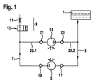
図1には、本発明による調量システムの第1の実施例がブロック図として示されている。タンク1の中には液体還元剤(尿素水溶液)がある。吸込配管3を介して、送出ポンプ5が必要に応じて液体還元剤をタンクから吸い込み、これを圧力配管7を介して調量モジュール9へと送出する。吸込配管3および圧力送出配管7という名称は、調量システムの標準動作、すなわち還元剤がタンクから調量モジュール9へ送出されるときを基準としたものである。
FIG. 1 shows a block diagram of a first embodiment of a metering system according to the invention. There is a liquid reducing agent ( urea aqueous solution ) in the tank 1. The
調量モジュール9は、このブロック図では、スロットル11と切換可能な2/2ウェイバルブ13との組み合わせとして表すことができる。方向制御弁13は無通電状態のときに閉じる。そのときには、液体還元剤が内燃機関(図示せず)の排ガス系統へノズル注入されることもない。送出ポンプ5が送出をしており、それによって圧力配管7の還元剤が高い圧力の下にあるとき、方向制御弁13はエンジン制御装置(図示せず)によって開かれ、それにより、液体還元剤が調量モジュール9のスロットル11で噴霧化され、細かく分散されて内燃機関の排ガス管へノズル注入される。
The metering module 9 can be represented in this block diagram as a combination of a
送出ポンプ5の送出圧力、および方向制御弁13の開放時間を通じて、排ガス系統へノズル注入される液体還元剤の量を制御することができる。本発明による調量システムでは、送出ポンプと並列に、ただしこれと反対向きの送出方向で、本発明による換気ポンプ15が設けられている。
Through the delivery pressure of the
送出ポンプ5が作動しているとき、換気ポンプ15は作動しておらず、その逆も成り立つ。ただし、両方のポンプ5,15がいずれも作動していない、本発明による調量システムの動作状態も存在する。
When the
送出ポンプ5の吸込側と送出側にはそれぞれ逆止め弁17,19が設けられている。これに対応する仕方で、換気ポンプ15の吸込側と圧力側にも同じく逆止め弁21および23が設けられている。送出ポンプ15と換気ポンプ15の送出方向は逆向きなので、逆止め弁17,19および21,23の阻止方向も反対方向を向いている。
Check
換気ポンプ15は、換気配管25を介して、送出ポンプ5の吸込配管3と圧力配管7に液圧接続されている。換気ポンプ15に関して吸込側にある換気配管25の区域は、符号25.1を有している。換気ポンプ15に関して圧力側にある換気配管25の区域は、符号25.2を有している。
The
図1に示す調量システムの通常動作では、逆止め弁21および23が換気配管25を遮断しており、これは、圧力配管7の圧力が前記の逆止め弁の開放圧力を下回っている限りにおいてである。
In the normal operation of the metering system shown in FIG. 1, the
図2には、本発明による調量システムの同じ実施例が、換気の動作モードで示されている。このケースでは送出ポンプ5は作動しておらず、換気ポンプ15が液体還元剤を調量モジュール9からタンク1に送り返す。換気ポンプ15が調量モジュール9ならびに圧力配管7の一部を換気できるようにするために、調量モジュール9の2/2ウェイバルブ13が開いている。このような切換位置が図2に示されている。
In FIG. 2, the same embodiment of the metering system according to the invention is shown in the operating mode of ventilation. In this case, the
図2に示す調量システムの換気のとき、逆止め弁17および17は吸込配管3と圧力配管7の各区域を遮断しており、これは、換気ポンプ157の送出圧力が、前述した逆止め弁の開放圧力を下回っている限りにおいてである。
When the metering system shown in FIG. 2 is ventilated, the
換気プロセスが完了するとただちに、調量モジュール9の方向制御弁13が再び閉じられて、換気ポンプ15が停止する。
As soon as the ventilation process is complete, the
換気プロセスの後には、調量モジュール9だけでなく、圧力配管7、換気配管25、および換気ポンプ15の各部分も空気ないし排ガスで充填される。このように、まだ液体還元剤で充填されている調量システムの領域にとって、すなわち特に送出ポンプ5、吸込配管3、および圧力配管7の一部にとって、還元剤が凍結したときに、空気で充填されている前述した領域を補償容積部として利用することができる。それにより、還元剤が凍結したときに生じる力は、送出ポンプ5や配管3,7での損傷の恐れがなくなる程度まで低減される。このことが特に該当するのは、送出ポンプ5と換気ポンプ15が共通のハウジングの中に配置されているときである。
After the ventilation process, not only the metering module 9 but also each part of the
図3には、本発明による調量システムの第2の実施例が示されている。第1の実施例との主要な相違点は、ダイヤフラムポンプとして構成された換気ポンプ15が、換気ポンプが無通電のとき、換気ポンプ15のダイヤフラムが常に換気配管25を閉止するように構成されていることにある。このことは、切換可能な方向制御弁26によって図示されている。その際には、方向制御弁26は区域25.1に図示されているが、換気配管25の区域25.2が閉じられるのが好ましい。
FIG. 3 shows a second embodiment of the metering system according to the invention. The main difference from the first embodiment is that the
換気ポンプ15のアクチュエータが通電されるとただちに、ダイヤフラムが換気配管25を再び解放し、それにより、図1および2を参照して説明した機能形態が再び生じることになる。つまり第2の実施例に基づく換気ポンプ15は、制御式の遮断弁26の機能を追加的に有している。そのために追加のコンポーネントは必要ないので、この追加の機能性は付加コストなしに実現される。
As soon as the actuator of the
制御式の遮断弁26としての送出ポンプの利用が有している利点は、換気配管25の断面を相応に設計することで、ダイヤフラムに対して作用するばねの非常に低いばね圧によって換気配管を密閉できることにある。それにより、換気配管にある両方の逆止め弁21,23のうちの一方を、送出ポンプ5の動作圧力に対しても密閉性を保つように設計する必要性がなくなる。
The advantage of using a delivery pump as a controlled shut-off
逆止め弁21および23の開放圧力は可能な限り低いほうがよい。換気ポンプ15の電磁式のアクチュエータは、どのストロークのときにも開放圧力を克服しなければならないからである。開放圧力が低いほど、アクチュエータを小型かつ軽量に施工することができる。したがって、換気ポンプ15のダイヤフラムを追加の遮断弁として利用すれば、逆止め弁21,23の開放圧力を低減できるばかりでなく、換気ポンプ15の電磁式のアクチュエータもいっそう小型に施工することができ、このことはコストと設計スペースを削減する。さらに、それによって換気ポンプ15を駆動するための電気エネルギー消費量も低減される。
The opening pressure of the
図4に示す実施例では、換気ポンプ15の吸込側には逆止め弁21(図1から3参照)に代えて吸込スロットル27が設けられている。吸込スロットル27は最終的には、換気配管25における断面狭隘部だけで実質的に成り立っているので、それによって必要なコンポーネントの数がいっそう少なくなり、このことは、本発明による調量システムの製造費用やロバスト性にプラスの影響を及ぼす。
In the embodiment shown in FIG. 4, a
図5を見ると明らかなように、換気ポンプ15の圧力側にある逆止め弁23を送出スロットル29で置き換えることもできる。ただし重要なのは、換気配管25に少なくとも1つの逆止め弁が存在していることである。
As can be seen from FIG. 5, the
自明のことではあるが、送出ポンプ5ならびに換気ポンプ15のダイヤフラムは電磁式のアクチュエータを通じてだけでなく、電動モータによって駆動することもできる。これ以外のポンプ原理、たとえばピストンポンプ、歯車ポンプ、ベーンポンプなどを採用することもできる。
Obviously, the diaphragms of the
逆止め弁17,19,21および/または23は、必要と設計に応じてばね部材で付勢することができ、それにより、その開放圧力をばねの初期応力によって広い範囲で調整可能である。これらの逆止め弁は、図4および5に示す実施例を参照して説明したように、部分的にスロットルで置き換えることもできる。
The
吸込側3、圧力配管7、および/または換気配管25で場合により必要となるフィルタは、実際の用途では部分的には必要であるが、図面を見やすくする都合から図示していない。同様のことは、圧力センサや流量センサについても当てはまる。しかし可能な場合には、このようなセンサ装置の組み込みも省略することができる。これらはコストを高いほうへと引き上げるからである。必要な場合には追加の電気加熱部を組み込むこともできる。しかしながら、それは多くのケースで必要ない。調量システムの凍結を防止するためには、ポンプ駆動装置の排熱で足りるのがごく普通だからである。このことは当然ながら、タンク1の中にある液体還元剤については当てはまらない。そこでは多くのケースにおいて、少なくとも凍った還元剤を溶かすための加熱部が必要である(図示せず)。
The filters that may be necessary on the
図6には、本発明による調量システムのさらに別の実施例が示されている。この実施例では、送出ポンプ5はダイヤフラムポンプとして構成されており、図3を参照して説明したのと類似する仕方で、切換可能な遮断弁28としても利用することができる。したがって、この点に関しては図3の換気ポンプ15との関連で述べたことを参照されたい。
FIG. 6 shows a further embodiment of a metering system according to the invention. In this embodiment, the
図7は、本発明による調量システムのさらに別の実施例のブロック図を示している。この実施例では、換気ポンプ15の吸込側にある第1の逆止め弁21と並列に、第2の逆止め弁31が設けられている。このとき逆止め弁21および31の阻止方向ないし通過方向は反対向きになっている。
FIG. 7 shows a block diagram of yet another embodiment of a metering system according to the present invention. In this embodiment, a
たとえば送出ポンプ5の作動中に圧力配管7で許容されない高い圧力が発生すると、第1の逆止め弁21が開く。その結果、換気ポンプ15のダイヤフラム(図7には図示せず)が高い圧力で付勢され、ダイヤフラムは高い圧力に基づいて撓む。それによって換気ポンプ15の送出室の容積が増え、それによって圧力ピークが部分的に低減される。圧力配管7の圧力が再び通常の値まで戻ると、ただちに換気ポンプ15の弾性的なダイヤフラムは第2の逆止め弁31を介して、圧力補償が実現されるまで、それまで送出室に収容していた量の液体尿素水溶液を再び圧力配管へ送り返す。
For example, when high pressure that is not allowed in the
圧力配管7の過圧が非常に大きいとき、換気ポンプ15の圧力側にある逆止め弁23が開き、そのために送出ポンプ5から送出される液体の一部が、圧力配管7から再び吸込配管3へ逆戻りすることもある。それによっても、許容される値への圧力低下ないし圧力制限が行われる。このように本発明のシステムは非常にロバスト性が高く、許容されない高い圧力が発生したときでも、損傷を受けることがない。
When the overpressure of the
図8の実施例では、換気ポンプ15の圧力側にある逆止め弁23と並列に、スロットル33が設けられている。このスロットルにより、電気式のアクチュエータを小型に製作することが可能である。すなわち、特に換気ポンプ15のダイヤフラムが追加の遮断弁26すなわち圧力保持弁26として構成されているとき、送出ポンプ5の吸込段階中に、強い負圧が換気ポンプ15の送出室で形成されることがあることが判明している。それは送出室が、換気配管25と逆止め弁23とを介して吸込配管3とつながっているためである。送出室で負圧が生じたとき、逆止め弁23の阻止作用が、換気ポンプ15の送出室と吸込配管3との間の圧力補償を妨げる。
In the embodiment of FIG. 8, a
送出室のこうした負圧は、非常に強力な電気式のアクチュエータによってしか克服することができない。本発明に基づくスロットルにより、送出室で負圧が生じたときに、換気ポンプ15の送出室と吸込配管3との間で圧力補償を行えることが保証される。その結果として、電気式のアクチュエータの駆動出力を低くすることができ、このことは、電気式のアクチュエータの所要設計スペースや重量にプラスの影響を及ぼす。この点に関するさらなる詳細は、図14−16およびその説明から明らかとなる。
This negative pressure in the delivery chamber can only be overcome by a very powerful electric actuator. The throttle according to the present invention ensures that pressure compensation can be performed between the delivery chamber of the
図9には、本発明による換気ポンプ15の一実施例の縦断面図が示されている。
FIG. 9 shows a longitudinal sectional view of an embodiment of the
電気式のアクチュエータ35は、実質的に、電磁石37と電機子39とを含んでいる。磁石37と電機子39の間には、電機子39を図9で見て左方に向かってダイヤフラム43に押し付けるばね41がある。ダイヤフラム43は外側で隆起部44により、換気ポンプ15のハウジング47に密閉式に挟み込まれており、それにより、図9で見てダイヤフラム43の右側には液体はない。ダイヤフラム43の他方の側には、換気ポンプ15の送出室45がハウジング47の中に構成されている。換気ポンプ15のハウジング47の中には、送出室45のほか、換気配管25の区域25.1および25.2の接続部も図示されている。ここで符号25.1は、換気配管25への換気ポンプ15の吸込側の接続部を表しており、それに対して符号25.2は、換気配管25への換気ポンプ15の圧力側の接続部を表している。逆止め弁21および23は、図9には示されていない。圧力側の接続部25.2の領域には、環状のシールシート49がハウジング47に構成されている。
The
電気式のアクチュエータが無通電のとき、ばね41が電機子39を押圧し、電機子によりダイヤフラム43がシールシート49に押し付けられ、それにより、換気配管25の接続部25.2が閉止される。電気式のアクチュエータ35が通電されるとただちに、磁石37が電機子39を図9で見て右方に動かし、それにより、ダイヤフラム43がシールシート49から持ち上げられ、そのようにして接続部25.1と送出室45との間で液圧接続が成立する。このように、図9の実施例に基づく本発明の換気ポンプ15は、同時に、アクチュエータ35が無通電に切り換わったときに換気配管25の接続部25.2を閉止する、制御可能な方向制御弁でもある。この機能性は追加のコンポーネントを必要とせず、巧みな設計的形態と、ダイヤフラム43、ポンプハウジングないしシールシート49、ならびに電気式のアクチュエータ35の相互調整によって実現される。それにより、製造時に追加のコストが発生することがない。
When the electric actuator is not energized, the
電気式のアクチュエータ35が1つまたは複数のコンデンサ(図示せず)の放電によって急激に通電されると、電機子39が非常に迅速に大きな力で引き寄せられ、それにより、圧力配管7および換気配管25の区域25.1の領域で、いっそう強力で急速な圧力降下が行われる。圧力配管7ないし換気配管25およびその中にあり圧力の下にある液体の弾性により、急激な圧力負荷軽減の結果として、圧力配管7の中にある液体の一部が換気ポンプ15によりタンクの方向へ押し出される。それにより、ただ1回ではあるが非常に急速に行われる換気ポンプ15の送出ストロークによって、調量モジュール9および圧力配管7の部分的な換気が保証され、それにより、これに続くシステムの凍結時にも、氷圧による損傷が発生しない。こうした高度にダイナミックなプロセスは、本発明との関連では衝撃的吸戻しと呼ばれ、調量システムないし換気ポンプ15の本発明に基づくいずれの実施例でも適用可能である。
When the
図10には、本発明に基づく換気の別の実施例が同じく部分的に破断して示されている。この実施例では、換気ポンプ15のサンドイッチ状の構造を良く見ることができる。電機子39の後に上から下に向かって、隆起部44を備えるダイヤフラム43と、バルブ・ダイヤフラム・プレート51とが後続している。
FIG. 10 shows another embodiment of ventilation according to the invention, also partially broken away. In this embodiment, the sandwich-like structure of the
この実施例でやはり良く見られるように、電機子39の図10で見て下側の端部には、ゴムまたはこれに類する弾性素材で押出被覆された弁皿53が構成されている。ダイヤフラム43は同じゴム素材で製作されており、電機子39と形状結合式に結合されている。
As is often seen in this embodiment, a
ただし弁皿53とダイヤフラム43の間には、電機子39の軸方向のストローク方向にある程度の間隔が存在しており、それにより、送出室45で生じる圧力は図10で見て「上方から」弁皿53に作用する。それにより、送出室45で生じる圧力は同時に、弁皿53をバルブ・ダイヤフラム・プレート51のシールシート49に押し付ける液圧式の閉止力として作用する。
However, there is a certain distance in the axial stroke direction of the
図10に示す実施例では、ダイヤフラム43は断面で見て波形に構成されている。それによりダイヤフラム43がいっそう弾性的になり、そのようにして、送出室45の中で圧力が上昇したときに容易に撓曲することができる。そのときダイヤフラム43は、図10で見て上方に向かって電機子39の方向に撓み、ついには電機子39に当接する。それにより、送出室45で極端に大きい過圧が発生したときでも、ダイヤフラム43が引き裂かれないことが保証される。
In the embodiment shown in FIG. 10, the
バルブ・ダイヤフラム・プレート51にはさらに別の接続部、すなわち接続部25.1と接続部25.3が見えている。換気ポンプ15の圧力側の出力部25.2は、図10では弁皿53で隠されている。
On the
接続部25.3は、本発明による換気ポンプ15が同時に圧力補償部材として利用されるときに、第2の逆止め弁31への液圧接続を成立させる(図7参照)。
The connection 25.3 establishes a hydraulic connection to the
図11は図10の細部をさらに拡大して示しており、バルブプレート57ならびにゴムプレート55が追加されている。バルブ・ダイヤフラム・プレート51の下方に、ゴムプレート55とバルブプレート57が配置されている。バルブ・ダイヤフラム・プレート51、ゴムプレート55、およびバルブプレート57は接続部25.1の下方で逆止め弁21を形成しており、その阻止方向は図11で見て上から下に向かって延びている。通過方向は、矢印59で図示されている。コンポーネント51,55および57のどの領域が逆止め弁21を形成するのかを明示するために、これらの領域が破線で囲まれている。
FIG. 11 shows the details of FIG. 10 in a further enlarged manner, and a
バルブプレート57には周回するウェブ61が構成されており、このウェブはバルブ・ダイヤフラム・プレート51の対応するウェブ63と協働作用して、ゴムプレート55を密閉式に挟み込むようになっている。ウェブ61と同軸に、バルブプレート57には、逆止め弁21が閉じたときにゴムプレート55が上に載るシールシート65が構成されている。シールシート65とウェブ61は、ゴムプレート55とともに環状通路67を区切っている。環状通路67の上方では、ゴムプレート55に複数の円弧状の破断部69が切り欠かれている。
The
逆止め弁21が圧力配管7(図11には図示せず)から換気配管25を介して、圧力配管7で生じている圧力により付勢され、この圧力が逆止め弁21の開放圧力よりも大きいとき、ゴムプレート55がシールシート65から持ち上げられ、それにより、バルブプレート57にある環状通路67への液圧接続が成立する。還元剤は環状通路67からゴムプレート55の破断部69を通って、換気ポンプの送出室45へと流れ込む。
このことは、穴71と送出室45の圧力差が十分に大きいとき、還元剤が矢印59の方向でバルブプレート57の穴69を通って流れることができることを意味している。
The
This means that when the pressure difference between the
圧力配管7と接続されている換気配管25の区域25.1における還元剤の圧力が、逆止め弁21の開放圧力よりも低下するとただちに、ゴムプレート55がその弾性に基づいて再びシールシート65の上へと降下し、そのようにして送出室45を閉止する。
As soon as the pressure of the reducing agent in the area 25.1 of the
第2の逆止め弁31も同じ構造を有しているが、ただし反対向きの通過方向を有している。したがって環状通路73とシールシート75は、バルブ・ダイヤフラム・プレート51に配置されている。
The
図11では、第2の逆止め弁31に付属しているゴムプレート55の破断部77は、少しの部分だけしか見えていない。
In FIG. 11, only a small portion of the
両方の逆止め弁21および31を比較すると明らかなように、第2の逆止め弁31のシールシート75は、第1の逆止め弁21のシールシート65の直径よりも小さくなっている。それにより、ゴムプレート55の厚みは同じままで、両方の逆止め弁21および31の開放圧力を調整することができる。すでに図7との関連で説明したとおり、第2の逆止め弁31の開放圧力が第1の逆止め弁21の開放圧力よりも高いと好ましく、このことは、シールシート75の小さい直径によって設計面から具体化される。
As is clear from a comparison of both
図11からすでに明らかなとおり、1つまたは複数の逆止め弁21,23,31を、本発明による換気ポンプ15に統合することが最低限のコストで可能である。それにより、バルブ・ダイヤフラム・プレート51ないしバルブプレート57を取り替えることで、本発明による換気ポンプ15のさまざまな態様を製作することができる。
As is clear from FIG. 11, it is possible at a minimum cost to integrate one or
図12には、図11の実施例の側面図が示されている。ここには、送出室45を換気配管25の圧力側の区域25.2と接続する逆止め弁23を良く見ることができる。逆止め弁23の通過方向は矢印79で図示されている。ここでもやはり同じ構造を見ることができる。
FIG. 12 shows a side view of the embodiment of FIG. Here, the
図12に示す実施例では、外側のシールシート49.2と内側のシールシート49.1とがバルブ・ダイヤフラム・プレート51に構成されており、アクチュエータ35が無通電のときにこれらの上に弁皿53が載り、それにより、換気ポンプ15の圧力側に対する送出室45の特別に良好な密閉が行われる。内側のシール隆起部49.1は、ばね41により印加される閉止力により漏れのない密閉が可能であるという帰結をもたらす。このことに特に意義があるのは、車両が停車しており、ばね41およびそれに伴って磁石37をどうしても必要であるよりも大型にすることなく、圧力配管7および/または調量モジュールおよび/または排ガス設備が満杯になるのを確実に防止しようとする場合である。
In the embodiment shown in FIG. 12, an outer seal sheet 49.2 and an inner seal sheet 49.1 are formed on a
バルブ・ダイヤフラム・プレート51には、ゴムプレート55とともに逆止め弁23を形成するシールシート81と環状通路83が構成されている。この図面では、弁皿53がシールシート49とどのように協働作用し、それによって第2の逆止め弁23を負荷軽減するかを良く見ることができる。
The
図12では、ダイヤフラム43のストロークないし弾性変形を制限するトーラス状の切欠きを磁石37が有している様子も良く見ることができる。それにより、許容されない高い圧力が送出室45で発生したときに、ダイヤフラム43の損傷を回避することができる。
In FIG. 12, it can be seen well that the
電機子39にある段部85は、一方では圧縮ばね41が電機子で自らを支えることができるようにする役目を果たし、他方では、この段部85は磁石37の中で電機子39を案内する役目も果たす。
The
図13ではゴムプレート55が透かして「下方から」示されており、それにより、バルブ・ダイヤフラム・プレート51にあるシールシートや、ダイヤフラム43の一部も見えるようになっている。この図面を見ると、逆止め弁21,23および31のそれぞれ異なる直径が明らかにわかる。
In FIG. 13, the
逆止め弁23は最大の穴を有しており、それにより、弁皿53がこの弁を閉止していなければ、送出室の過圧が小さいときすでに開くようになっている。それにより、換気ポンプ15の作動時にエネルギー消費量が最低限に抑えられる。それに対して、換気ポンプ15の吸込側にある第2の逆止め弁31はシールシート75の最小の直径を有しており、それにより、この逆止め弁は比較的大きい圧力のときに初めて開く。
The
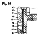
図14から16には、本発明による換気ポンプ15のさらに別の実施例が示されている。
FIGS. 14 to 16 show a further embodiment of a
逆止め弁21および23は、先ほど説明したのとは若干異なる設計形態となっている。ただしその機能に変わりはない。図14および15では、バルブプレート51にある接続部25.1を取り囲むシールシート49の上に、ダイヤフラム43がどのように載るのかを良く見ることができる。
The
特に図14を拡大した図面である図15では、ダイヤフラム43が別の隆起部87の上に載っている様子を同じく良く見ることができる。すなわち送出室45は円環状のジオメトリーを有しており、半径方向外側で隆起部87により区切られるとともに、内側ではシールシート49により区切られている。
In particular, FIG. 15, which is an enlarged view of FIG. 14, shows that the
送出ポンプ5(たとえば図1参照)の作動時に液体還元剤がタンクから吸い出されると、吸込配管3の圧力が一時的に低下する。その結果として、換気配管25の圧力側の部分にある逆止め弁23が開き、その結果、送出室45の圧力も低下する。送出室45のこのように低い圧力は、逆止め弁23の阻止作用により、吸込配管3で再び周囲圧力が生じているときにも維持されたままとなる。
If the liquid reducing agent is sucked out of the tank during the operation of the delivery pump 5 (see, for example, FIG. 1), the pressure in the
送出室45のこうした低い圧力は、ダイヤフラム43がバルブプレート51ないしシールシート49および隆起部87に向かって、ある程度まで引っ張られるという帰結につながる。それが意味するのは、電機子39およびこれに伴ってダイヤフラム43をシールシート49および隆起部87から持ち上げるために、非常に強い力が電機子39ないし磁石37により印加されなくてはならないことである。そのためには、大型で高価な電気式のアクチュエータ35が必要になる。
Such a low pressure in the
そこで本発明では、送出室45を換気配管25.2と接続し、ないしは吸込配管3と間接的に接続するスロットル33が、バルブプレート57に構成されている(図8および図16のブロック図を参照)。スロットル33は、吸込配管3と送出室45の間で圧力補償がなされるように作用し、それにより、シールシート49ないし隆起部87からダイヤフラム43を持ち上げるのに必要な力が劇的に低減される。それにより、小型の電気式のアクチュエータ35でも利用することができ、このことは、コストと設計スペースを削減する。さらに、本発明による換気ポンプ15の電力消費量も少なくなる。
Therefore, in the present invention, the
1 タンク
3 吸込配管
5 送出ポンプ
7 圧力配管
9 調量モジュール
15 換気ポンプ
1
Claims (17)
前記送出ポンプ(5)および/または前記換気ポンプ(15)の吸込側と送出側にはそれぞれ第1の逆止め弁(17,19,21,23)が設けられていて、
前記換気ポンプ(15)の圧力側(25.2)には前記第1の逆止め弁(23)と並列にスロットル(33)または絞りが設けられていることを特徴とする(図8)調量システム。 The metering system for aqueous urea solution includes a delivery module comprising a delivery pump (5), a metering module (9), and a tank (1), the delivery pump (5) and the tank (1 ) Are connected to each other via a suction pipe (3), and the delivery pump (5) and the metering module (9) are connected to each other via a pressure pipe (7), such as In the metering system, a ventilation pump (15) is arranged in parallel with the delivery pump (5), the ventilation pump (15) being connected to the metering module (9) on the suction side and on the pressure side. Connected to the tank (1),
A first check valve (17, 19, 21, 23) is provided on each of the suction side and the delivery side of the delivery pump (5) and / or the ventilation pump (15),
The pressure side (25.2) of the ventilation pump (15) is provided with a throttle (33) or a throttle in parallel with the first check valve (23) (FIG. 8). Quantity system.
Applications Claiming Priority (3)
| Application Number | Priority Date | Filing Date | Title |
|---|---|---|---|
| DE102011081628.3 | 2011-08-26 | ||
| DE102011081628A DE102011081628A1 (en) | 2011-08-26 | 2011-08-26 | Dosing system for a liquid reducing agent |
| PCT/EP2012/063342 WO2013029849A1 (en) | 2011-08-26 | 2012-07-09 | Dosing system for a liquid reducing agent |
Publications (3)
| Publication Number | Publication Date |
|---|---|
| JP2014524542A JP2014524542A (en) | 2014-09-22 |
| JP2014524542A5 JP2014524542A5 (en) | 2015-10-29 |
| JP6012732B2 true JP6012732B2 (en) | 2016-10-25 |
Family
ID=46466558
Family Applications (1)
| Application Number | Title | Priority Date | Filing Date |
|---|---|---|---|
| JP2014526428A Active JP6012732B2 (en) | 2011-08-26 | 2012-07-09 | Metering system for liquid reducing agents |
Country Status (6)
| Country | Link |
|---|---|
| US (1) | US9562455B2 (en) |
| EP (1) | EP2748439B1 (en) |
| JP (1) | JP6012732B2 (en) |
| CN (1) | CN103782002B (en) |
| DE (1) | DE102011081628A1 (en) |
| WO (1) | WO2013029849A1 (en) |
Families Citing this family (23)
| Publication number | Priority date | Publication date | Assignee | Title |
|---|---|---|---|---|
| RU2573436C2 (en) * | 2011-08-22 | 2016-01-20 | Камминз Эмишн Солюшн Инк. | Valves for urea injection system |
| DE102011088217A1 (en) | 2011-12-12 | 2013-06-13 | Robert Bosch Gmbh | Dosing arrangement for a liquid exhaust aftertreatment agent and dosing |
| DE102011088221A1 (en) | 2011-12-12 | 2013-06-13 | Robert Bosch Gmbh | Dosing arrangement for a liquid exhaust aftertreatment agent and dosing |
| DE102011089516B4 (en) | 2011-12-22 | 2021-08-12 | Robert Bosch Gmbh | Pump for sucking back a liquid exhaust gas aftertreatment agent, dosing arrangement and method for dosing and sucking back |
| DE102011090070A1 (en) | 2011-12-29 | 2013-07-04 | Robert Bosch Gmbh | Exhaust gas treatment device for selective catalytic reduction of nitrogen oxides contained in exhaust gases of engine, has shut-off valve arranged in pressure line between feed pump and metering unit |
| DE102012004726A1 (en) * | 2012-03-07 | 2013-09-12 | Emitec Gesellschaft Für Emissionstechnologie Mbh | Feed unit for a liquid additive |
| DE102012212562B4 (en) * | 2012-07-18 | 2020-11-26 | Robert Bosch Gmbh | Method of operating a pump system |
| DE102013211234A1 (en) | 2013-06-17 | 2014-12-18 | Robert Bosch Gmbh | Adjustable magnetic circuit for pressure indication |
| DE102014211057A1 (en) | 2013-06-19 | 2014-12-24 | Robert Bosch Gmbh | Recirculation pump with stop damping |
| SE539369C2 (en) * | 2014-06-12 | 2017-08-15 | Scania Cv Ab | System and method for transferring and evacuating fluid from the secondary tank to a main tank in a vehicle |
| CN106150618B (en) * | 2015-04-01 | 2023-08-15 | 天纳克(苏州)排放系统有限公司 | Urea injection assembly |
| DE102015118147A1 (en) * | 2015-10-23 | 2017-04-27 | Eberspächer Exhaust Technology GmbH & Co. KG | Apparatus and method for dispensing reactant in the exhaust stream of an internal combustion engine |
| DE102015226463A1 (en) * | 2015-12-22 | 2017-06-22 | Robert Bosch Gmbh | Magnetic actuator for a delivery unit |
| CN107246302A (en) * | 2017-08-09 | 2017-10-13 | 华中科技大学无锡研究院 | A kind of urea pumping system |
| DE102017213958A1 (en) | 2017-08-10 | 2019-02-14 | Robert Bosch Gmbh | Magnetic actuator for a delivery unit |
| DE102017214481A1 (en) * | 2017-08-21 | 2019-02-21 | Robert Bosch Gmbh | Water injection device for an internal combustion engine |
| DE102017215658A1 (en) | 2017-09-06 | 2019-03-07 | Robert Bosch Gmbh | Device for connecting metallic components with plastic components in a delivery unit |
| DE102017217891A1 (en) * | 2017-10-09 | 2019-04-11 | Robert Bosch Gmbh | Delivery module for conveying a fluid |
| DE102017218452A1 (en) | 2017-10-16 | 2019-04-18 | Robert Bosch Gmbh | Magnetic actuator for a delivery unit |
| DE102017220535A1 (en) * | 2017-11-17 | 2019-05-23 | Robert Bosch Gmbh | A method of operating a reagent dosing system, apparatus and conduit network for carrying out the method |
| DE102017222448A1 (en) | 2017-12-12 | 2019-06-13 | Robert Bosch Gmbh | Pump with stop damping |
| DE102018200572A1 (en) * | 2018-01-15 | 2019-07-18 | Robert Bosch Gmbh | Method for checking an SCR system with at least two metering valves |
| CN111482067A (en) * | 2020-03-05 | 2020-08-04 | 华电电力科学研究院有限公司 | Method for adding active substances to improve efficiency in SNCR (selective non-catalytic reduction) denitration technology |
Family Cites Families (41)
| Publication number | Priority date | Publication date | Assignee | Title |
|---|---|---|---|---|
| JPS59517A (en) | 1982-06-23 | 1984-01-05 | Mazda Motor Corp | Exhaust gas purifying device of diesel engine |
| JPS59144106U (en) * | 1983-03-18 | 1984-09-26 | 日産自動車株式会社 | Burner for regeneration of trap for collecting exhaust particulates |
| JPH059517A (en) * | 1991-06-28 | 1993-01-19 | Sumitomo Metal Ind Ltd | Method for operating blast furnace |
| US5433238A (en) * | 1992-12-18 | 1995-07-18 | Vlsi Technology, Inc. | Pumping system for evacuating reactor chambers |
| US5522218A (en) * | 1994-08-23 | 1996-06-04 | Caterpillar Inc. | Combustion exhaust purification system and method |
| DE19726392A1 (en) * | 1997-06-21 | 1998-12-24 | Bosch Gmbh Robert | Mixture dispenser |
| DE19738859A1 (en) * | 1997-09-05 | 1999-03-11 | Bosch Gmbh Robert | Mixture dispenser |
| DE19819579C1 (en) * | 1998-04-30 | 1999-09-30 | Siemens Ag | Secondary treatment of exhaust from lean burn diesel engine with SCR catalyst, minimizing pump usage and energy consumption |
| JP2000325754A (en) * | 1999-05-17 | 2000-11-28 | Osaka Gas Co Ltd | Exhaust gas denitration system for cogeneration |
| DE19956493C1 (en) * | 1999-11-24 | 2001-01-04 | Siemens Ag | Device for removing nitrogen oxides from I.C. engine exhaust gas comprises a flow-through measuring device that determines the amount of excess reductant arranged in the pressure relieving line |
| US6470673B1 (en) * | 2000-02-22 | 2002-10-29 | Ford Global Technologies, Inc. | Control of a NOX reductant delivery system |
| DE10047516A1 (en) * | 2000-09-22 | 2002-04-18 | Bosch Gmbh Robert | Method and device for dosing a reducing agent for removing nitrogen oxides from exhaust gases |
| JP2003003962A (en) * | 2001-06-20 | 2003-01-08 | Nikki Co Ltd | Diaphragm pump |
| DE10139142A1 (en) * | 2001-08-09 | 2003-02-20 | Bosch Gmbh Robert | Exhaust gas treatment unit and measuring device for determining a concentration of a urea-water solution |
| DE10161132A1 (en) * | 2001-12-12 | 2003-06-26 | Siemens Ag | Diaphragm pump with integrated pressure sensor |
| US6810661B2 (en) * | 2002-08-09 | 2004-11-02 | Ford Global Technologies, Llc | Method and system for freeze protecting liquid NOx reductants for vehicle application |
| DE10254981A1 (en) * | 2002-11-26 | 2004-06-03 | Robert Bosch Gmbh | Device for removing a reducing agent from an apparatus for the aftertreatment of exhaust gases from an internal combustion engine |
| JP2004346808A (en) * | 2003-05-21 | 2004-12-09 | Denso Corp | Solenoid valve driving device |
| EP2426329B1 (en) * | 2003-09-19 | 2013-05-01 | Nissan Diesel Motor Co., Ltd. | Exhaust gas purification device of engine |
| US20050252201A1 (en) * | 2004-05-17 | 2005-11-17 | Lecea Oscar A | Method and apparatus for reducing NOx emissions |
| US7594393B2 (en) * | 2004-09-07 | 2009-09-29 | Robert Bosch Gmbh | Apparatus for introducing a reducing agent into the exhaust of an internal combustion engine |
| DE102004046881A1 (en) * | 2004-09-28 | 2006-04-13 | Robert Bosch Gmbh | Delivery system for a medium, in particular for the treatment of exhaust gases of an internal combustion engine, exhaust gas purification device and method for operating a delivery system |
| DE102004050023A1 (en) * | 2004-10-13 | 2006-04-27 | L'orange Gmbh | Device for the metered injection of a reducing agent into the exhaust gas tract of an internal combustion engine |
| DE102004054238A1 (en) * | 2004-11-10 | 2006-05-11 | Robert Bosch Gmbh | Dosing system and method for operating a dosing system |
| FR2879239A1 (en) * | 2004-12-15 | 2006-06-16 | Inergy Automotive Systems Res | SYSTEM FOR STORING AND INJECTING AN ADDITIVE IN EXHAUST GASES OF AN ENGINE |
| DE112006001140B4 (en) * | 2005-06-04 | 2014-06-05 | Eichenauer Heizelemente Gmbh & Co. Kg | Urea supply system for an exhaust gas purification catalyst and suitable heating insert for this purpose |
| JP2007056741A (en) * | 2005-08-24 | 2007-03-08 | Nissan Diesel Motor Co Ltd | Exhaust emission control device for engine |
| DE102006027487A1 (en) * | 2005-09-12 | 2007-03-15 | Robert Bosch Gmbh | Vehicle tank for a liquid reducing agent, in particular for a urea solution |
| WO2008006840A1 (en) * | 2006-07-13 | 2008-01-17 | Inergy Automotive Systems Research (Société Anonyme) | System and process for storing an additive and injecting it into the exhaust gases of an engine |
| FR2921911A1 (en) * | 2007-09-21 | 2009-04-10 | Inergy Automotive Systems Res | System for storing and injecting additive solution into exhaust gases of diesel engine for use in heavy goods vehicle, has one tank from which solution is withdrawn when another tank is non-operational |
| US20090194604A1 (en) * | 2008-01-19 | 2009-08-06 | Clyde Meriwether Smith | Pulsed spray system of reduced power consumption |
| JP5475243B2 (en) * | 2008-03-07 | 2014-04-16 | ボッシュ株式会社 | Control device for reducing agent supply device, recovery method for reducing agent, and exhaust purification device |
| DE102008022991A1 (en) * | 2008-05-09 | 2009-11-12 | Emitec Gesellschaft Für Emissionstechnologie Mbh | Device for conveying a reducing agent and method for producing a motor vehicle |
| DE102008040463A1 (en) * | 2008-07-16 | 2010-01-21 | Robert Bosch Gmbh | Device for metering in fuel |
| US8459012B2 (en) * | 2008-11-19 | 2013-06-11 | Caterpillar Inc. | Method for purging a dosing system |
| US9051864B2 (en) * | 2009-04-16 | 2015-06-09 | Inergy Automotive Systems Research (Société Anonyme) | System and process for storing an additive and injecting it into the exhaust gases of an engine |
| JP5388286B2 (en) * | 2009-06-19 | 2014-01-15 | ボッシュ株式会社 | Exhaust purification device and control method thereof |
| DE102009037564B4 (en) * | 2009-08-14 | 2013-08-29 | Continental Automotive Gmbh | Apparatus and method for dosing a reducing agent in an exhaust gas tract of an internal combustion engine |
| DE102009029408B4 (en) | 2009-09-14 | 2023-10-19 | Robert Bosch Gmbh | Method for monitoring the function of an SCR catalyst system |
| DE102010039102B4 (en) * | 2010-08-09 | 2013-10-31 | Mtu Friedrichshafen Gmbh | Supply device, internal combustion engine, generator unit, method for supplying an exhaust system of an internal combustion engine with a solution containing reducing agent and control device |
| DE102011002425A1 (en) * | 2011-01-04 | 2012-07-05 | Robert Bosch Gmbh | Conveying device for supplying an exhaust aftertreatment system of an internal combustion engine with a reducing agent and method |
-
2011
- 2011-08-26 DE DE102011081628A patent/DE102011081628A1/en not_active Withdrawn
-
2012
- 2012-07-09 CN CN201280041092.7A patent/CN103782002B/en active Active
- 2012-07-09 JP JP2014526428A patent/JP6012732B2/en active Active
- 2012-07-09 WO PCT/EP2012/063342 patent/WO2013029849A1/en active Application Filing
- 2012-07-09 EP EP12733139.5A patent/EP2748439B1/en active Active
- 2012-07-09 US US14/241,360 patent/US9562455B2/en active Active
Also Published As
| Publication number | Publication date |
|---|---|
| US9562455B2 (en) | 2017-02-07 |
| US20140227120A1 (en) | 2014-08-14 |
| CN103782002B (en) | 2017-03-22 |
| WO2013029849A1 (en) | 2013-03-07 |
| EP2748439A1 (en) | 2014-07-02 |
| EP2748439B1 (en) | 2017-10-04 |
| JP2014524542A (en) | 2014-09-22 |
| DE102011081628A1 (en) | 2013-02-28 |
| CN103782002A (en) | 2014-05-07 |
Similar Documents
| Publication | Publication Date | Title |
|---|---|---|
| JP6012732B2 (en) | Metering system for liquid reducing agents | |
| JP4415929B2 (en) | High pressure fuel supply pump | |
| JP4595996B2 (en) | High pressure fuel supply device for internal combustion engine | |
| CN101029695B (en) | Electromagnetic actuator performing quick response | |
| US8882475B2 (en) | Electromagnetic flow rate control valve and high-pressure fuel supply pump using the same | |
| JP4701227B2 (en) | Plunger high pressure fuel pump | |
| JP2014524542A5 (en) | ||
| JP2009535562A (en) | Pressure control valve with emergency and ventilation functions | |
| JP2002115622A (en) | High pressure fuel supply device | |
| JPWO2017203861A1 (en) | High pressure fuel supply pump | |
| CN102197213A (en) | High-pressure fuel pump for an internal combustion engine | |
| JP2008309016A (en) | Hydraulic control device | |
| JP4585977B2 (en) | High pressure fuel supply pump and method of assembling the same | |
| JP4728389B2 (en) | Device for injecting fuel | |
| US7543568B1 (en) | Fuel pressure amplifier for improved cranking performance | |
| US20180245489A1 (en) | Solenoid-actuated pressure-relief valve | |
| CN106414967A (en) | Method for operating a fuel-supply system for an internal combustion engine | |
| JP5030381B2 (en) | Pressure pulse generator and pressure pulse generation method | |
| JP4775488B2 (en) | High pressure fuel supply device for internal combustion engine | |
| JP5514564B2 (en) | Fuel supply device | |
| US6520156B2 (en) | High-pressure fuel supply system | |
| JP2010038139A (en) | Accumulating fuel injection device | |
| JP2004518845A (en) | Gas exchange valve device for internal combustion engine | |
| JP4552834B2 (en) | Fuel injection device | |
| JP5780581B2 (en) | Pressure control valve for common rail fuel injection control system |
Legal Events
| Date | Code | Title | Description |
|---|---|---|---|
| A977 | Report on retrieval |
Free format text: JAPANESE INTERMEDIATE CODE: A971007 Effective date: 20150219 |
|
| A131 | Notification of reasons for refusal |
Free format text: JAPANESE INTERMEDIATE CODE: A131 Effective date: 20150302 |
|
| A601 | Written request for extension of time |
Free format text: JAPANESE INTERMEDIATE CODE: A601 Effective date: 20150602 |
|
| A524 | Written submission of copy of amendment under article 19 pct |
Free format text: JAPANESE INTERMEDIATE CODE: A524 Effective date: 20150901 |
|
| A131 | Notification of reasons for refusal |
Free format text: JAPANESE INTERMEDIATE CODE: A131 Effective date: 20160210 |
|
| A521 | Request for written amendment filed |
Free format text: JAPANESE INTERMEDIATE CODE: A523 Effective date: 20160419 |
|
| TRDD | Decision of grant or rejection written | ||
| A01 | Written decision to grant a patent or to grant a registration (utility model) |
Free format text: JAPANESE INTERMEDIATE CODE: A01 Effective date: 20160825 |
|
| A61 | First payment of annual fees (during grant procedure) |
Free format text: JAPANESE INTERMEDIATE CODE: A61 Effective date: 20160920 |
|
| R150 | Certificate of patent or registration of utility model |
Ref document number: 6012732 Country of ref document: JP Free format text: JAPANESE INTERMEDIATE CODE: R150 |
|
| R250 | Receipt of annual fees |
Free format text: JAPANESE INTERMEDIATE CODE: R250 |
|
| R250 | Receipt of annual fees |
Free format text: JAPANESE INTERMEDIATE CODE: R250 |
|
| R250 | Receipt of annual fees |
Free format text: JAPANESE INTERMEDIATE CODE: R250 |
|
| R250 | Receipt of annual fees |
Free format text: JAPANESE INTERMEDIATE CODE: R250 |
|
| R250 | Receipt of annual fees |
Free format text: JAPANESE INTERMEDIATE CODE: R250 |