JP6012521B2 - Angle adjuster - Google Patents
Angle adjuster Download PDFInfo
- Publication number
- JP6012521B2 JP6012521B2 JP2013059314A JP2013059314A JP6012521B2 JP 6012521 B2 JP6012521 B2 JP 6012521B2 JP 2013059314 A JP2013059314 A JP 2013059314A JP 2013059314 A JP2013059314 A JP 2013059314A JP 6012521 B2 JP6012521 B2 JP 6012521B2
- Authority
- JP
- Japan
- Prior art keywords
- arm
- winding
- shaft portion
- rotation direction
- tightening
- Prior art date
- Legal status (The legal status is an assumption and is not a legal conclusion. Google has not performed a legal analysis and makes no representation as to the accuracy of the status listed.)
- Active
Links
- 238000004804 winding Methods 0.000 claims description 300
- 230000002093 peripheral effect Effects 0.000 claims description 118
- 238000003825 pressing Methods 0.000 description 162
- 238000003780 insertion Methods 0.000 description 28
- 230000037431 insertion Effects 0.000 description 28
- 125000006850 spacer group Chemical group 0.000 description 27
- 230000001105 regulatory effect Effects 0.000 description 18
- 239000002184 metal Substances 0.000 description 15
- 230000005489 elastic deformation Effects 0.000 description 6
- 230000002265 prevention Effects 0.000 description 5
- 239000002023 wood Substances 0.000 description 5
- 229910000831 Steel Inorganic materials 0.000 description 4
- 230000000903 blocking effect Effects 0.000 description 4
- 239000010959 steel Substances 0.000 description 4
- 239000000470 constituent Substances 0.000 description 3
- 230000003247 decreasing effect Effects 0.000 description 3
- 230000000694 effects Effects 0.000 description 3
- 239000000463 material Substances 0.000 description 3
- 238000012545 processing Methods 0.000 description 3
- 238000004080 punching Methods 0.000 description 3
- 230000033228 biological regulation Effects 0.000 description 2
- 238000004891 communication Methods 0.000 description 2
- 230000007423 decrease Effects 0.000 description 2
- 230000001771 impaired effect Effects 0.000 description 2
- 238000000034 method Methods 0.000 description 2
- 239000013585 weight reducing agent Substances 0.000 description 2
- 229910000639 Spring steel Inorganic materials 0.000 description 1
- 238000005452 bending Methods 0.000 description 1
- 239000004973 liquid crystal related substance Substances 0.000 description 1
- 238000012986 modification Methods 0.000 description 1
- 230000004048 modification Effects 0.000 description 1
- 238000010791 quenching Methods 0.000 description 1
- 230000000171 quenching effect Effects 0.000 description 1
- 239000011347 resin Substances 0.000 description 1
- 229920005989 resin Polymers 0.000 description 1
- 238000011144 upstream manufacturing Methods 0.000 description 1
Images


Landscapes
- Chairs For Special Purposes, Such As Reclining Chairs (AREA)
Description
本発明は、家具類などに用いられる角度調節器及び該角度調節器を備えたリクライニング椅子に関する。 The present invention relates to an angle adjuster used for furniture and the like and a reclining chair provided with the angle adjuster.
なお本明細書では、特に明示しない限り、「位置固定」とは「枢着」を含む意味で用いられるとともに、「固定位置」とは「枢着位置」を含む意味で用いられる。 In this specification, unless otherwise specified, “fixed position” is used to include “pivot attachment”, and “fixed position” is used to include “pivot attachment position”.
家具類として例えばリクライニング椅子における背フレームの傾倒角度を調節するための角度調節器には様々な構成のものが知られており、例えば、特開2002−177082号公報(特許文献1)、特開2006−230720号公報(特許文献2)及び特開2006−340798号公報(特許文献3)に開示されたものが知られている。 As furniture, for example, an angle adjuster for adjusting a tilt angle of a back frame in a reclining chair is known in various configurations. For example, JP 2002-177082 (Patent Document 1), JP What was disclosed in 2006-230720 (patent document 2) and JP-A-2006-340798 (patent document 3) is known.
これらの角度調節器は、第1アームと第2アームとを具備しており、第2アームが第1アームに対して相対的に回転可能になるように第1アームと第2アームとが連結されている。そして、第1アームに座フレームが取り付けられるとともに、第2アームに背フレームが取り付けられる。これらの角度調節器は、ギヤ歯とラチェット爪との噛合を利用して第1アームに対する第2アームの展開角度を段階的に調節しうるように構成されている。したがって、第2アームの展開角度を無段階に調節することができず、使用者の好みや疲労度合いに応じた細かい角度調節ができなかった。また、第2アームの展開角度を調節するため第2アームを正回転方向(例えば第2アームの展開角度を小さくする方向)に回転させる時に「カチッ」という音が発生し、周囲の人に迷惑が掛かるという難点があった。 These angle adjusters have a first arm and a second arm, and the first arm and the second arm are connected so that the second arm can rotate relative to the first arm. Has been. A seat frame is attached to the first arm, and a back frame is attached to the second arm. These angle adjusters are configured so that the deployment angle of the second arm with respect to the first arm can be adjusted stepwise by utilizing the engagement between the gear teeth and the ratchet pawl. Therefore, the deployment angle of the second arm could not be adjusted steplessly, and fine angle adjustment according to the user's preference and the degree of fatigue could not be performed. Also, when the second arm is rotated in the forward rotation direction (for example, the direction in which the second arm deployment angle is decreased) to adjust the deployment angle of the second arm, a “click” sound is generated, which is annoying to the surrounding people. There was a difficulty that it took.
特開2009−45395号公報(特許文献4)に開示された角度調節器は、第1アームに対する第2アームの展開角度を無段階に調節できるようになっている。 The angle adjuster disclosed in Japanese Patent Application Laid-Open No. 2009-45395 (Patent Document 4) can continuously adjust the deployment angle of the second arm with respect to the first arm.
この角度調節器では、第1アーム(固定金具)に円筒状の固定ボス部が固定状態に且つ突出して設けられるとともに、第2アーム(可動金具)に回転ボス部が一体回転可能に設けられている。回転ボス部の基部は固定ボス部内に固定ボス部の先端側から回転可能に挿入されており、回転ボス部の先部は固定ボス部の先端から突出して配置されている。固定ボス部には捻りコイルバネが外挿されている。捻りコイルバネの一端部は回転ボス部の先端に固定されており、捻りコイルバネの他端部は第1アームに固定されている。そして、第2アームの回転ボス部が逆回転方向に回転した場合には、捻りコイルバネの一端部が回転ボス部と一体に逆回転方向に回転し、これにより、捻りコイルバネが縮径して固定ボス部の外周面を巻き締め、もって第2アームの逆回転方向の回転を阻止するように構成されている。 In this angle adjuster, the first arm (fixed metal fitting) is provided with a cylindrical fixed boss portion protruding in a fixed state, and the second arm (movable metal fitting) is provided with a rotating boss portion so as to be integrally rotatable. Yes. The base portion of the rotating boss portion is rotatably inserted into the fixed boss portion from the distal end side of the fixed boss portion, and the tip portion of the rotating boss portion is disposed so as to protrude from the distal end of the fixed boss portion. A torsion coil spring is extrapolated to the fixed boss portion. One end of the torsion coil spring is fixed to the tip of the rotating boss, and the other end of the torsion coil spring is fixed to the first arm. When the rotating boss portion of the second arm rotates in the reverse rotation direction, one end portion of the torsion coil spring rotates in the reverse rotation direction integrally with the rotation boss portion, thereby reducing the diameter of the torsion coil spring and fixing it. The outer peripheral surface of the boss part is tightened to prevent the second arm from rotating in the reverse rotation direction.
しかしながら、この角度調節器では、その厚さ寸法は固定ボス部の突出長さと回転ボス部の先部の突出長さとの合計長さによって決定されるため、角度調節器の小型化(薄厚化)を図ることが困難であった。 However, in this angle adjuster, the thickness dimension is determined by the total length of the protruding length of the fixed boss portion and the protruding length of the tip portion of the rotating boss portion. Therefore, the angle adjuster is downsized (thinned). It was difficult to plan.
さらに、角度調節器の組立時において、第2アームの展開角度の調節可能範囲の全範囲に亘って捻りコイルバネの巻締め力が固定ボス部の外周面に加わるように、捻りコイルバネの一端部を回転ボス部の先端に固定しなければならないので、その組立作業が困難であった。 Further, at the time of assembling the angle adjuster, one end of the torsion coil spring is applied so that the winding force of the torsion coil spring is applied to the outer peripheral surface of the fixed boss portion over the entire adjustable range of the deployment angle of the second arm. Since it has to be fixed to the tip of the rotating boss part, the assembling work was difficult.
本発明は、上述した技術背景に鑑みてなされたもので、その目的は、小型化を図ることができ、且つ、組立作業を容易に行うことができる角度調節器を提供することにある。 The present invention has been made in view of the above-described technical background, and an object of the present invention is to provide an angle adjuster that can be reduced in size and can be easily assembled.
本発明は以下の手段を提供する。 The present invention provides the following means.
[1] 巻締め部材を備えた第1アームと、
回転軸部を備えた第2アームと、を具備し、
前記回転軸部は、前記第2アームに一体回転可能に設けられており、
前記回転軸部の軸線方向視において、前記巻締め部材の一端部及び他端部は、互いに離間して前記第1アームに設けられており、
前記第1アームと前記第2アームとが、前記回転軸部の外周面に前記巻締め部材の巻締め部が巻かれた状態で前記第2アームが前記回転軸部を中心に前記第1アームに対して相対的に回転可能になるように連結されており、
前記第2アームの正回転方向の回転動作により前記回転軸部の外周面と前記巻締め部材の前記巻締め部の内周面との接触部に発生する正回転方向の摩擦力が、前記巻締め部材に前記回転軸部の外周面に対する緩め方向に作用することにより、前記回転軸部の外周面への前記巻締め部材の巻締め力が減少して、前記第2アームの正回転方向の回転が許容されるものとなされるとともに、
前記第2アームの逆回転方向の回転動作により前記接触部に発生する逆回転方向の摩擦力が、前記巻締め部材に前記回転軸部の外周面に対する巻締め方向に作用することにより、前記回転軸部の外周面への前記巻締め部材の巻締め力が増加して、前記第2アームの逆回転方向の回転が阻止されるものとなされていることを特徴とする角度調節器。
[1] A first arm provided with a winding member;
A second arm having a rotating shaft portion,
The rotating shaft portion is provided to be rotatable integrally with the second arm,
In the axial direction view of the rotating shaft portion, one end portion and the other end portion of the winding member are provided apart from each other on the first arm,
The first arm and the second arm are configured such that the second arm is centered on the rotation shaft portion in a state where the winding tightening portion of the tightening member is wound on the outer peripheral surface of the rotation shaft portion. Connected to be rotatable relative to
The frictional force in the positive rotation direction generated at the contact portion between the outer peripheral surface of the rotary shaft portion and the inner peripheral surface of the winding fastening portion of the winding fastening member by the rotational movement of the second arm in the positive rotational direction is the winding force. By acting on the tightening member in the loosening direction with respect to the outer peripheral surface of the rotating shaft portion, the tightening force of the tightening member on the outer peripheral surface of the rotating shaft portion decreases, and the second arm moves in the positive rotation direction. Rotation is allowed and
The friction force in the reverse rotation direction generated in the contact portion by the rotation operation of the second arm in the reverse rotation direction acts on the winding member in the winding direction with respect to the outer peripheral surface of the rotary shaft portion, thereby causing the rotation. An angle adjuster characterized in that the tightening force of the tightening member on the outer peripheral surface of the shaft portion is increased to prevent the second arm from rotating in the reverse rotation direction.
[2] 前記巻締め部材は、前記巻締め方向及び前記緩め方向にバネ弾性を有しており、
前記回転軸部の外周面に前記巻締め部材の前記巻締め部が巻かれた状態において、前記巻締め部材のバネ弾性力によって前記回転軸部の外周面が常時、巻き締められている前項1記載の角度調節器。
[2] The winding member has spring elasticity in the winding direction and the loosening direction,
The preceding
[3] 前記巻締め部材の前記一端部及び前記他端部は、前記第1アームに位置固定されており、
前記回転軸部の軸線方向視において、
前記巻締め部材の前記一端部の前記第1アームへの固定位置を第1固定位置、
前記巻締め部材の前記他端部の前記第1アームへの固定位置を第2固定位置、
前記第1固定位置と前記巻締め部材の前記巻締め部の中心位置との間の直線距離を第1距離、及び、
前記第2固定位置と前記巻締め部材の前記巻締め部の中心位置との間の直線距離を第2距離とするとき、
前記第2距離は前記第1距離よりも短く設定されており、
前記第2アームの正回転方向は、前記巻締め部材の前記巻締め部における前記第1固定位置側部位を前記回転軸部の外周面から巻き解く回転方向に設定されるとともに、
前記第2アームの逆回転方向は、前記巻締め部材の前記巻締め部における前記第1固定位置側部位を前記回転軸部の外周面に巻き付ける回転方向に設定されている前項1又は2記載の角度調節器。
[3] The one end portion and the other end portion of the winding member are fixed to the first arm,
In the axial direction view of the rotating shaft part,
A fixing position of the one end of the winding member to the first arm is a first fixing position,
A fixing position of the other end of the winding member to the first arm is a second fixing position;
A linear distance between the first fixed position and the center position of the winding portion of the winding member is a first distance, and
When a linear distance between the second fixed position and the center position of the winding portion of the winding member is a second distance,
The second distance is set shorter than the first distance,
The positive rotation direction of the second arm is set to a rotation direction that unwinds the first fixed position side portion in the winding portion of the winding member from the outer peripheral surface of the rotation shaft portion, and
The reverse rotation direction of the second arm is set to a rotation direction in which the first fixed position side portion of the tightening portion of the tightening member is wound around an outer peripheral surface of the rotation shaft portion. Angle adjuster.
[4] 前記回転軸部の軸線方向視において、
前記第1固定位置と前記巻締め部材の前記巻締め部の中心位置との間を結んだ直線を基準線とするとき、
前記第2固定位置は、前記巻締め部の中心位置を中心として前記基準線に対して±45°の範囲内に配置している前項3記載の角度調節器。
[4] In the axial direction view of the rotating shaft portion,
When a straight line connecting the first fixed position and the center position of the winding portion of the winding member is a reference line,
The angle adjuster according to
[5] 前記回転軸部の軸線方向視において、
前記第1固定位置と前記巻締め部材の前記巻締め部の中心位置との間を結んだ直線を基準線とするとき、
前記第2固定位置は、前記巻締め部の中心位置を中心として前記基準線に対して0°から前記第2アームの前記回転軸部の逆回転方向の下流側へ45°までの範囲内に配置されている前項3記載の角度調節器。
[5] In the axial direction view of the rotating shaft portion,
When a straight line connecting the first fixed position and the center position of the winding portion of the winding member is a reference line,
The second fixed position is within a range from 0 ° to 45 ° downstream of the rotation shaft portion of the second arm in the reverse rotation direction with respect to the reference line with the center position of the tightening portion as a center. 4. The angle adjuster according to
[6] 前記巻締め部材は、第1アームとは別体に形成されている前項1〜5のいずれかに記載の角度調節器。 [6] The angle adjuster according to any one of [1] to [5], wherein the winding member is formed separately from the first arm.
[7] 前記巻締め部材の前記一端部及び前記他端部は、前記第1アームに枢着されている前項6記載の角度調節器。 [7] The angle adjuster according to [6], wherein the one end and the other end of the winding member are pivotally attached to the first arm.
[8] 前記巻締め部材は、金属素板からその厚さ方向に前記巻締め部材の外形形状に打ち抜かれて形成されたものであり、且つ、前記巻締め方向及び前記緩め方向にバネ弾性を有している前項1〜7のいずれかに記載の角度調節器。
[8] The winding member is formed by punching from the metal base plate into the outer shape of the winding member in the thickness direction, and has spring elasticity in the winding direction and the loosening direction. 8. The angle adjuster according to any one of the preceding
[9] 前記巻締め部材の前記巻締め部の前記内周面は、前記回転軸部の前記外周面に、前記回転軸部の軸心位置を中心とした180°以上の領域で接触している前項1〜8のいずれかに記載の角度調節器。
[9] The inner peripheral surface of the tightening portion of the winding member is in contact with the outer peripheral surface of the rotating shaft portion in a region of 180 ° or more centered on the axial center position of the rotating shaft portion. 9. The angle adjuster according to any one of the preceding
[10] 前記巻締め部材の前記巻締め部の前記内周面は、前記回転軸部の前記外周面の形状に対応した形状に形成されている前項1〜9のいずれかに記載の角度調節器。
[10] The angle adjustment according to any one of
[11] 前記逆回転方向の摩擦力が前記巻締め部材に前記巻締め方向に作用することにより発生する前記巻締め部材の前記巻締め方向の変形量を規制する規制手段を備えている前項1〜10のいずれかに記載の角度調節器。
[11] The preceding
[12] 前記規制手段は、規制部材と、前記回転軸部にその軸線方向に延びて設けられた規制孔と、を備えるとともに、
前記規制孔の径は、前記規制部材の径よりも大きく設定されており、
前記規制部材は、前記規制孔内に配置されており、
前記規制手段は、前記巻締め部材の前記巻締め方向の変形量が所定量に到達した時に、前記規制孔の内周面が前記規制部材に衝当し、これにより前記巻締め部材の前記巻締め方向の変形量を規制するものとなされている前項11記載の角度調節器。
[12] The restricting means includes a restricting member, and a restricting hole provided in the rotating shaft portion so as to extend in the axial direction thereof.
The diameter of the restriction hole is set larger than the diameter of the restriction member,
The restriction member is disposed in the restriction hole,
When the amount of deformation of the tightening member in the tightening direction reaches a predetermined amount, the restricting means abuts the inner peripheral surface of the restricting hole against the restricting member, and thereby the winding of the tightening member. 12. The angle adjuster according to 11 above, wherein the amount of deformation in the tightening direction is restricted.
[13] 前記第1アームには、互いに離間して対向状に配置された一対の外側板部が設けられるとともに、前記巻締め部材及び前記回転軸部が前記両外側板部の間に配置されており、
前記規制孔は、前記回転軸部にその軸線方向に貫通して設けられており、
前記規制部材はリベットで構成されており、
前記各外側板部には、前記規制部材用挿通孔が設けられており、
前記両外側板部は、前記両挿通孔と前記規制孔とに連通して挿通された前記規制部材を介して互いに連結されている前項12記載の角度調節器。
[13] The first arm is provided with a pair of outer plate portions that are arranged to be spaced apart from each other and face each other, and the winding member and the rotating shaft portion are arranged between the outer plate portions. And
The restriction hole is provided through the rotation shaft portion in the axial direction thereof,
The restricting member is composed of rivets,
Each outer plate portion is provided with the insertion hole for the restriction member,
13. The angle adjuster according to
[14] さらに、前記規制手段は、前記正回転方向の摩擦力が前記巻締め部材に前記緩め方向に作用することにより発生する前記巻締め部材の前記緩め方向の変形量が所定量に到達した時に、前記規制孔の内周面が前記規制部材に衝当し、これにより前記巻締め部材の前記緩め方向の変形量を規制するものとなされている前項12又は13記載の角度調節器。 [14] Further, in the restricting means, the amount of deformation in the loosening direction of the winding member generated by the frictional force in the positive rotation direction acting on the winding member in the loosening direction has reached a predetermined amount. 14. The angle adjuster according to claim 12 or 13, wherein an inner peripheral surface of the restriction hole hits the restriction member, thereby restricting a deformation amount of the winding member in the loosening direction.
[15] 前記第1アームには、正回転方向に最大回転した前記第2アームが衝当して前記第2アームの正回転方向の回転を止めるストッパ部が設けられている前項1〜14のいずれかに記載の角度調節器。
[15] The first arm according to the
[16] 前記第2アームの逆回転方向の回転の阻止を解除する解除手段を備えている前項1〜15のいずれかに記載の角度調節器。 [16] The angle adjuster according to any one of [1] to [15], further including release means for releasing blocking of the rotation of the second arm in the reverse rotation direction.
[17] 前記解除手段は、前記巻締め部材の前記巻締め力が減少するように前記巻締め部材を前記緩め方向に押圧変形させて前記第2アームの逆回転方向の回転の阻止を解除する押圧部材と、前記第2アームに一体回転可能に設けられた回転板部と、を備えるとともに、
前記押圧部材は、前記巻締め部材を前記緩め方向に押圧変形させる押圧位置と、前記巻締め部材を押圧変形させない非押圧位置との間を移動可能に配置されており、
前記回転板部には、前記第2アームが正回転方向に最大回転した際に、前記非押圧位置に配置された前記押圧部材を前記押圧位置まで押す第1押し部が設けられている前項16記載の角度調節器。
[17] The releasing means releases the blocking of the rotation of the second arm in the reverse rotation direction by pressing and deforming the winding member in the loosening direction so that the winding force of the winding member is reduced. A pressing member, and a rotating plate portion provided on the second arm so as to be integrally rotatable,
The pressing member is disposed so as to be movable between a pressing position that presses and deforms the winding fastening member in the loosening direction and a non-pressing position that does not press deform the winding fastening member.
The above-described
[18] さらに、前記回転板部には、前記第2アームが逆回転方向に最大回転した際に、前記押圧位置に配置された前記押圧部材を前記非押圧位置まで押す第2押し部が設けられている前項17記載の角度調節器。 [18] Further, the rotating plate portion is provided with a second pressing portion that presses the pressing member disposed at the pressing position to the non-pressing position when the second arm rotates in the reverse rotation direction to the maximum. 18. The angle adjuster according to item 17 above.
[19] 前記押圧部材は、前記巻締め部材の前記巻締め部における前記他端部側部位の外周面の外側に配置されており、
前記他端部側部位の外周面に、前記押圧部材を前記非押圧位置に保持する凹所が形成されており、
前記第1アームには、前記押圧位置に配置された前記押圧部材を前記他端部側部位の外周面に押し付ける押付け部が設けられており、
前記押付け部は、前記押付け部と前記他端部側部位の外周面との間の間隔が前記押圧部材の厚さ寸法よりも小さくなるように配置されており、
前記押圧部材が前記非押圧位置から前記押圧位置に配置されるように前記押付け部と前記他端部側部位の外周面との間に強制的に圧入されることにより、前記押圧部材が前記押付け部で前記他端部側部位の外周面に押し付けられて前記巻締め部材を前記緩め方向に押圧変形させるものとなされている前項17又は18記載の角度調節器。
[19] The pressing member is disposed on the outer side of the outer peripheral surface of the other end side portion of the tightening portion of the tightening member,
On the outer peripheral surface of the other end side portion, a recess is formed to hold the pressing member at the non-pressing position.
The first arm is provided with a pressing portion that presses the pressing member arranged at the pressing position against the outer peripheral surface of the other end side portion,
The pressing portion is arranged such that a distance between the pressing portion and the outer peripheral surface of the other end side portion is smaller than a thickness dimension of the pressing member.
The pressing member is forcibly press-fitted between the pressing portion and the outer peripheral surface of the other end portion side so that the pressing member is disposed from the non-pressing position to the pressing position, whereby the pressing member is pressed. The angle adjuster according to the preceding
[20] 前記第1アームは、前記巻締め部材を一対、備えており、
前記両巻締め部材は、両巻締め部材の間に隙間を形成するためのスペーサ部材を挟んで対向状に配置されており、
前記スペーサ部材は、前記第1アームに固定状態に設けられており、
前記回転軸部は、前記回転板部の略中央部に前記回転板部の厚さ方向両側に突出して一体回転可能に設けられており、
前記両巻締め部材の間における前記隙間に前記回転板部が配置されるとともに、前記両巻締め部材の前記両巻締め部の内側にそれぞれ前記回転軸部が回転可能に配置されており、
前記押圧部材は、前記両巻締め部材の前記両巻締め部における前記両他端部側部位の外周面の外側に前記両他端部側部位の両外周面に跨がって配置されており、
前記スペーサ部材には、前記押圧位置に配置された前記押圧部材を前記両他端部側部位の両外周面に押し付ける押付け部が設けられており、
前記押付け部は、前記押付け部と前記両他端部側部位の両外周面との間の間隔が前記押圧部材の厚さ寸法よりも小さくなるように配置されており、
前記押圧部材が前記非押圧位置から前記押圧位置に配置されるように前記押付け部と前記両他端部側部位の両外周面との間に強制的に圧入されることにより、前記押圧部材が前記押付け部で前記両他端部側部位の両外周面に押し付けられて前記巻締め部材を押圧変形させるものとなされている前項17又は18記載の角度調節器。
[20] The first arm includes a pair of the fastening members.
The both tightening members are arranged opposite to each other with a spacer member for forming a gap between the both tightening members,
The spacer member is fixed to the first arm;
The rotating shaft portion is provided at a substantially central portion of the rotating plate portion so as to project integrally on both sides in the thickness direction of the rotating plate portion so as to be integrally rotatable.
The rotating plate portion is disposed in the gap between the both tightening members, and the rotation shaft portions are rotatably disposed inside the both tightening portions of the both tightening members,
The pressing member is disposed outside the outer peripheral surface of the other end portion side portion of the both tightening portions of the both tightening members and straddling both outer peripheral surfaces of the other end portion side portion. ,
The spacer member is provided with a pressing portion that presses the pressing member disposed at the pressing position against both outer peripheral surfaces of the other end portions.
The pressing portion is arranged such that a distance between the pressing portion and both outer peripheral surfaces of the other end side portions is smaller than a thickness dimension of the pressing member,
The pressing member is forcibly press-fitted between the pressing portion and both outer peripheral surfaces of the other end side portions so that the pressing member is disposed from the non-pressing position to the pressing position. 19. The angle adjuster according to claim 17 or 18, wherein the pressing member is pressed against both outer peripheral surfaces of the other end side portions to press and deform the winding member.
[21] 前記巻締め部材を上側及び下側のうち少なくとも一方側から覆うカバー部材が着脱自在に取り付けられている前項1〜20のいずれかに記載の角度調節器。
[21] The angle adjuster according to any one of
[22] 前記回転軸部は、前記第2アームとは別体に形成されており、
前記回転軸部には、断面非円形状の嵌合孔が設けられており、
前記第2アームには、前記嵌合孔に対応する断面非円形状の嵌合軸部が一体回転可能に設けられており、
前記嵌合軸部が前記嵌合孔に着脱自在に嵌合されることにより、前記回転軸部が前記第2アームに一体回転可能に連結されている前項1〜21のいずれかに記載の角度調節器。
[22] The rotating shaft portion is formed separately from the second arm,
The rotation shaft portion is provided with a fitting hole having a non-circular cross section,
The second arm is provided with a fitting shaft portion having a non-circular cross section corresponding to the fitting hole so as to be integrally rotatable,
The angle according to any one of the preceding
[23] 前項1〜22のいずれかに記載の角度調節器の第1アームに座フレームが取り付けられるとともに、前記角度調節器の第2アームに背フレームが取り付けられていることを特徴とするリクライニング椅子。
[23] A reclining characterized in that a seat frame is attached to the first arm of the angle adjuster according to any one of the preceding
本発明は以下の効果を奏する。 The present invention has the following effects.
前項[1]の角度調節器では、巻締め部材の巻締め力は回転軸部の外周面に作用するので、上記特開2009−45395号公報に開示された角度調節器における第1アームの固定ボス部を不要とし、これにより角度調節器の小型化(薄厚化)を図ることができる。 In the angle adjuster of the above item [1], the tightening force of the tightening member acts on the outer peripheral surface of the rotating shaft portion, so the first arm is fixed in the angle adjuster disclosed in the above Japanese Patent Application Laid-Open No. 2009-45395. The boss portion is unnecessary, and thus the angle adjuster can be downsized (thinned).
さらに、巻締め部材の一端部及び他端部は第1アームに設けられているので、巻締め部材の一端部を回転軸部に固定する必要がない。そのため、角度調節器の組立作業を容易に行うことができる。 Furthermore, since the one end part and the other end part of the winding member are provided on the first arm, it is not necessary to fix the one end part of the winding member to the rotating shaft part. Therefore, the assembly work of the angle adjuster can be easily performed.
さらに、この角度調節器は、巻締め部材の巻締め力の増減によって第2アームの回転を許容したり阻止したりするものなので、第1アームに対する第2アームの展開角度を無段階に調節する構成を採用することもできる。 Furthermore, since this angle adjuster allows or prevents the rotation of the second arm by increasing or decreasing the tightening force of the tightening member, it adjusts the deployment angle of the second arm with respect to the first arm steplessly. A configuration can also be adopted.
前項[2]では、巻締め部材が巻締め方向及び緩め方向にバネ弾性を有することにより、巻締め方向や緩め方向に変形した巻締め部材を初期位置に確実に復帰させることができる。 In the preceding item [2], the winding member has spring elasticity in the winding direction and the loosening direction, so that the winding member deformed in the winding direction and the loosening direction can be reliably returned to the initial position.
さらに、巻締め部材のバネ弾性力によって回転軸部の外周面が常時、巻き締められていることにより、第2アームの正回転方向への不慮の回転を防止することができる。さらに、第2アームに逆回転方向の荷重が加わった際に逆回転方向の摩擦力を巻締め部材に確実に作用させることができ、これにより第2アームの逆回転方向の回転を確実に阻止することができる。 Furthermore, since the outer peripheral surface of the rotating shaft portion is always tightened by the spring elastic force of the tightening member, it is possible to prevent the second arm from being accidentally rotated in the positive rotation direction. Furthermore, when a load in the reverse rotation direction is applied to the second arm, a friction force in the reverse rotation direction can be reliably applied to the winding member, thereby reliably preventing the rotation of the second arm in the reverse rotation direction. can do.
前項[3]では、正回転方向の摩擦力が巻締め部材に緩め方向に確実に作用し、これにより第2アームの正回転方向の回転を確実に許容することができるし、また逆回転方向の摩擦力が巻締め部材に巻締め方向に確実に作用し、これにより第2アームの逆回転方向の回転を確実に阻止することができる。 In the previous item [3], the frictional force in the forward rotation direction acts on the winding member in the loosening direction with certainty, so that the second arm can be reliably allowed to rotate in the forward rotation direction, and the reverse rotation direction. Thus, the frictional force reliably acts on the tightening member in the tightening direction, so that the rotation of the second arm in the reverse rotation direction can be reliably prevented.
前項[4]では、第2固定位置が巻締め部の中心位置を中心として基準線に対して±45°の範囲内に配置していることにより、正回転方向の摩擦力が巻締め部材に緩め方向に更に確実に作用し、これにより第2アームの正回転方向の回転を更に確実に許容することができる。さらに、逆回転方向の摩擦力が巻締め部材に巻締め方向に更に確実に作用し、これにより第2アームの逆回転方向の回転を更に確実に阻止することができる。 In the preceding item [4], the second fixed position is arranged within a range of ± 45 ° with respect to the reference line with the center position of the tightening portion as the center, so that the frictional force in the forward rotation direction is applied to the tightening member. It acts more reliably in the loosening direction, and thereby allows the rotation of the second arm in the positive rotation direction to be permitted more reliably. Furthermore, the frictional force in the reverse rotation direction acts on the winding member more reliably in the winding direction, and thereby the rotation of the second arm in the reverse rotation direction can be more reliably prevented.
前項[5]では、第2固定位置が巻締め部の中心位置を中心として基準線に対して0°から第2アームの回転軸部の逆回転方向の下流側へ45°までの範囲内に配置されていることにより、逆回転方向の摩擦力が巻締め部材に巻締め方向に更により一層確実に作用し、これにより第2アームの逆回転方向の回転を更により一層確実に阻止することができる。 In the preceding item [5], the second fixed position is within a range from 0 ° to 45 ° to the downstream side in the reverse rotation direction of the rotation shaft portion of the second arm with respect to the reference line with the center position of the winding portion as the center. By being arranged, the frictional force in the reverse rotation direction acts on the winding member more reliably in the winding direction, thereby further reliably preventing the rotation of the second arm in the reverse rotation direction. Can do.
前項[6]では、締め部材は第1アームとは別体に形成されていることにより、巻締め部材を容易に製造することができる。 In the preceding item [6], since the fastening member is formed separately from the first arm, the winding fastening member can be easily manufactured.
前項[7]では、巻締め部材の一端部及び他端部が第1アームに枢着されていることにより、巻締め部材が巻締め方向及び緩め方向にそれぞれ確実に動作し、これにより第2アームの所定回転方向の回転を確実に阻止及び許容することができる。 In the preceding item [7], since the one end and the other end of the winding member are pivotally attached to the first arm, the winding member operates reliably in the winding direction and the loosening direction. The rotation of the arm in the predetermined rotation direction can be reliably prevented and allowed.
前項[8]では、巻締め部材が金属素板からその厚さ方向に巻締め部材の外形形状に打ち抜かれて形成されたものなので、巻締め部材を容易に製作することができる。 In the preceding item [8], since the winding member is formed by punching the outer shape of the winding member in the thickness direction from the metal base plate, the winding member can be easily manufactured.
さらに、巻締め部材が巻締め方向及び緩め方向にバネ弾性を有することにより、巻締め方向や緩め方向に変形した巻締め部材を初期位置に確実に復帰させることができる。 Further, since the winding member has spring elasticity in the winding direction and the loosening direction, the winding member deformed in the winding direction and the loosening direction can be reliably returned to the initial position.
前項[9]では、巻締め部材の巻締め部の内周面が、回転軸部の外周面に、回転軸部の軸心位置を中心とした180°以上の領域で接触していることにより、回転軸部の巻締め部からの脱落を確実に防止することができる。 In the previous item [9], the inner peripheral surface of the tightening portion of the tightening member is in contact with the outer peripheral surface of the rotating shaft portion in a region of 180 ° or more centering on the axial center position of the rotating shaft portion. Further, it is possible to reliably prevent the rotating shaft portion from falling off from the winding tightening portion.
前項[10]では、巻締め部材の巻締め部の内周面が、回転軸部の外周面の形状に対応した形状に形成されていることにより、巻締め部の内周面と回転軸部の外周面との接触面積を増加させることができる。そのため、回転軸部の直径を大きくしなくても第2アームの逆回転方向の回転の阻止に必要な逆回転方向の摩擦力を得ることができ、その結果、角度調節器の小型化を図りうる。 In the previous item [10], the inner peripheral surface of the tightening member is formed in a shape corresponding to the shape of the outer peripheral surface of the rotating shaft portion, whereby the inner peripheral surface of the tightening portion and the rotating shaft portion are formed. The contact area with the outer peripheral surface can be increased. Therefore, it is possible to obtain the friction force in the reverse rotation direction necessary for preventing the rotation of the second arm in the reverse rotation direction without increasing the diameter of the rotation shaft portion. As a result, the angle adjuster can be miniaturized. sell.
前項[11]では、角度調節器は巻締め部材の巻締め方向の変形量を規制する規制手段を備えているので、巻締め部材がその弾性変形域を超えて巻締め方向に変形することによる巻締め部材の塑性変形を防止でき、これにより巻締め部材を初期状態に確実に復帰させることができる。 In the previous item [11], the angle adjuster includes a restricting means for restricting the amount of deformation of the winding member in the winding direction, so that the winding member is deformed in the winding direction beyond its elastic deformation range. The plastic deformation of the winding member can be prevented, whereby the winding member can be reliably returned to the initial state.
前項[12]では、巻締め部材の塑性変形を確実に防止できる。 In the preceding item [12], plastic deformation of the winding member can be reliably prevented.
前項[13]では、巻締め部材及び回転軸部が両外側板部の間に配置されることにより、巻締め部材及び回転軸部が正常に動作するように巻締め部材及び回転軸部を両外側板部で保護することができる。さらに、両外側板部がリベットで構成された規制部材を介して互いに連結されていることにより、両外側板部が互いに開き方向に変形するのを規制部材で阻止することができ、したがって巻締め部材及び回転軸部を両外側板部で確実に保護することができる。 In the previous item [13], the winding member and the rotary shaft portion are disposed between the outer side plate portions, so that the winding member and the rotary shaft portion are both operated so that the winding member and the rotary shaft portion operate normally. It can be protected by the outer plate part. Further, since the outer side plate portions are connected to each other via a regulating member made of rivets, the outer side plate portions can be prevented from being deformed in the opening direction by the regulating member, and accordingly, the tightening is performed. A member and a rotating shaft part can be reliably protected by both outer side board parts.
前項[14]では、巻締め部材がその弾性変形域を超えて緩め方向に変形することによる巻締め部材の塑性変形を防止できる。 In the preceding item [14], it is possible to prevent plastic deformation of the winding member due to the winding member deforming in the loosening direction beyond its elastic deformation range.
前項[15]では、第1アームには正回転方向に最大回転した第2アームが衝当して第2アームの正回転方向の回転を止めるストッパ部が設けられていることにより、第1アームを正回転方向の最大回転位置に確実に止めることができる。 In the previous item [15], the first arm is provided with a stopper portion that stops the rotation of the second arm in the positive rotation direction by abutting the second arm that has rotated maximum in the positive rotation direction. Can be reliably stopped at the maximum rotation position in the forward rotation direction.
前項[16]では、第2アームの逆回転方向の回転の阻止を解除手段によって解除することができる。 In the previous item [16], the prevention of the rotation of the second arm in the reverse rotation direction can be canceled by the releasing means.
前項[17]では、回転板部には、第2アームが正回転方向に最大回転した際に、非押圧位置に配置された押圧部材を押圧位置まで押す第1押し部が設けれらているので、第2アームを正回転方向に最大回転させることにより、押圧部材を押圧位置に配置させることができ、そのため、第2アームの逆回転方向の回転の阻止の解除作業を容易に行うことができる。 In the previous item [17], the rotating plate portion is provided with a first pressing portion that presses the pressing member disposed at the non-pressing position to the pressing position when the second arm rotates to the maximum in the normal rotation direction. Therefore, by rotating the second arm to the maximum in the forward rotation direction, the pressing member can be disposed at the pressing position, and therefore, the work for releasing the blocking of the rotation of the second arm in the reverse rotation direction can be easily performed. it can.
前項[18]では、回転板部には、第2アームが逆回転方向に最大回転した際に、押圧位置に配置された押圧部材を非押圧位置まで押す第2押し部が設けられているので、第2アームを逆回転方向に最大回転させることにより、押圧部材を非押圧位置に配置させることができ、そのため、第2アームを元の状態に復帰させる作業を容易に行うことができる。 In the previous item [18], the rotary plate portion is provided with the second pressing portion that presses the pressing member arranged at the pressing position to the non-pressing position when the second arm rotates to the maximum in the reverse rotation direction. By rotating the second arm to the maximum in the reverse rotation direction, the pressing member can be arranged at the non-pressing position, and therefore, the operation of returning the second arm to the original state can be easily performed.
前項[19]では、第2アームの逆回転方向の回転の阻止を確実に解除することができるし、第2アームを元の状態に確実に復帰させることができる。 In the previous item [19], the prevention of the rotation of the second arm in the reverse rotation direction can be reliably released, and the second arm can be reliably returned to the original state.
前項[20]では、前項[19]の効果と同様の効果を奏する。さらに、押圧部材は、両巻締め部材の両巻締め部における両他端部側部位の両外周面に跨がって配置されているので、押圧部材は押圧位置と押圧位置との間を安定良く移動可能である。そのため、押圧部材の位置を押圧位置と非押圧位置とにスムーズに切り替えることができるし、押圧部材の脱落を防止できる。 In the previous item [20], the same effect as in the previous item [19] is obtained. Furthermore, since the pressing member is disposed across both outer peripheral surfaces of the other end portions of the both tightening portions of the both tightening members, the pressing member is stable between the pressing position and the pressing position. It can move well. Therefore, the position of the pressing member can be switched smoothly between the pressing position and the non-pressing position, and the pressing member can be prevented from falling off.
前項[21]では、巻締め部材が正常に動作するように巻締め部材をカバー部材で覆うことができる。さらに、カバー部材は着脱自在に角度調節器に取り付けられるので、カバー部材の取付け作業を容易に行うことができる。 In the preceding item [21], the winding member can be covered with the cover member so that the winding member operates normally. Furthermore, since the cover member is detachably attached to the angle adjuster, the cover member can be easily attached.
前項[22]では、第2アームの嵌合軸部が回転軸部の嵌合孔に着脱自在に嵌合されている。したがって、嵌合軸部を嵌合孔から離脱させ、次いで嵌合軸部を嵌合孔に対して回転させて嵌合孔に再度、嵌合させることにより、第2アームの展開角度の調節可能範囲を維持したままで第2アームの展開開始角度及び展開終了角度を変更することができる。 In the preceding item [22], the fitting shaft portion of the second arm is detachably fitted into the fitting hole of the rotating shaft portion. Therefore, the deployment angle of the second arm can be adjusted by detaching the fitting shaft portion from the fitting hole, and then rotating the fitting shaft portion with respect to the fitting hole and fitting again into the fitting hole. The deployment start angle and deployment end angle of the second arm can be changed while maintaining the range.
前項[23]のリクライニング椅子では、角度調節器において前項[1]〜[22]のいずれかの効果と同様の効果を奏する。 In the reclining chair of the preceding item [23], the angle adjuster has the same effect as any one of the preceding items [1] to [22].
次に、本発明の幾つかの実施形態について図面を参照して以下に説明する。 Next, several embodiments of the present invention will be described below with reference to the drawings.
図1〜14Hは、本発明の第1実施形態に係る角度調節器を説明するための図である。 1 to 14H are views for explaining an angle adjuster according to the first embodiment of the present invention.
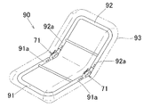
図1に示すように、本第1実施形態の角度調節器71は、リクライニング椅子として例えば座椅子90における背フレーム92の傾倒角度の調節に用いられるものである。
As shown in FIG. 1, the
座椅子90の背フレーム92は金属製丸パイプ材から製作されている。また、座椅子90の座フレーム91も同じく金属製丸パイプ材から製作されている。座フレーム91の左右各後端部91aと背フレーム92の左右各下端部92aとは、座フレーム91に対する背フレーム92の傾倒角度が調節可能になるように左右一対の本第1実施形態の角度調節器71、71を介して連結されている。なお、これらのフレーム91、92はクッション体93の内部に配置される。
The
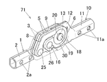
この角度調節器71は、角度調節金具とも呼ばれているものであり、図2〜6に示すように第1アーム1と第2アーム10とを具備している。第1アーム1及び第2アーム10はいずれも金属製であり、詳述すると例えば鋼製である。そして、第2アーム10が第1アーム1に対して相対的に所定の展開角度θの範囲内にて正逆両回転方向に回転可能になるように、第1アーム1と第2アーム10とが互いに連結されている。図5において、θは、第1アーム1に対する第2アーム10の展開角度である。この角度調節器71において、第2アーム10の展開角度θの調節可能な範囲は例えば約80°〜約180°に設定されている。
The
第1アーム1は、座フレーム91の後端部91aに取り付けられる取付け部2を備えている。この取付け部2はパイプ状である。そして、この取付け部2が座フレーム91の後端部91aの中空部内に挿入され、この状態で取付け部2に座フレーム91の後端部91aが複数のリベットによって取り付けられる。そのため、取付け部2には複数のリベット用挿通孔2aが穿設されている。
The
取付け部2の基端部には、互いに離間して対向状に配置された一対の外側板部3、3と、両外側板部3、3の下端同士を連結した底板部4とが一体に形成されている(図5及び6参照)。なお、本実施形態では、説明の便宜上、両外側板部3、3が対向している方向を角度調節器71の「左右方向」と定義する。この方向は、図2に示すように角度調節器71の厚さ方向Tと一致しており、更に、後述する回転軸部13の軸線方向とも一致している。
The base end portion of the
さらに、第1アーム1は、図8〜11に示すように、左右一対の巻締め部材5、5と、スペーサ部材8とを備えている。巻締め部材5は、第1アーム1及びスペーサ部材8とは別体に形成されたものである。また、スペーサ部材8は、第1アーム1及び巻締め部材5とは別体に形成されたものである。そして、両巻締め部材5、5及びスペーサ部材8は、図4及び11に示すように両外側板部3、3の間に配置されている。これらの部材の構成については後述する。
Further, the
第2アーム10は、図8及び9に示すように、左右一対の第2アーム構成片10a、10a同士が互いに一体的に組み合わせて構成されたものである。なお、図8に示すように両構成片10a、10aの組み合わせ前の状態において、各構成片10aの組み合わせ面には、互いに組み合わされた両構成片10a、10a間の位置ずれを防止するための互いに嵌合可能な嵌合凸部10b及び嵌合凹部10cがそれぞれ形成されている。
As shown in FIGS. 8 and 9, the
この第2アーム10は、背フレーム92の下端部92aに取り付けられる取付け部11を備えている。この取付け部11はパイプ状である。そして、この取付け部11が背フレーム92の下端部92aの中空部内に挿入され、この状態で取付け部11に背フレームの下端部92aが複数のリベットによって取り付けられる。そのため、取付け部11には複数のリベット用挿通孔11aが穿設されている。
The
取付け部11の基端部には回転板部12が一体に形成されており、これにより回転板部12が第2アーム10に一体回転可能に設けられている。さらに、回転板部12の略中央部には、回転板部12の厚さ方向の両側にそれぞれ突出した回転軸部13が一体に形成されており、これにより回転軸部13が第2アーム10に一体回転可能に設けられている。回転軸部13は断面円形状のボス部から構成されている。回転軸部13の外周面13aは、回転軸部13の軸心を中心とした円弧面で形成されている。なお、この回転軸部13は回転板部12の略中央部が局部的にプレス曲げ加工されて形成されたものである。
A
ここで、図2及び4において、Jは回転軸部13の軸線を示している。さらに、この角度調節器71において回転軸部13の軸線方向視とは、軸線Jに沿う方向視のことであり、即ち矢印Zの方向視のことである。
Here, in FIGS. 2 and 4, J indicates the axis of the
第1アーム1において、図8及び9に示すように、左右一対の巻締め部材5、5は、互いに同一形状及び同一寸法である。各巻締め部材5は、金属製であり、バネ弾性を有している。スペーサ部材8は、両巻締め部材5、5の間に回転板部12の厚さに対応する隙間9を形成するためものであり、板状である。その材質は鋼等の金属である。そして、両巻締め部材5、5は、図10及び11に示すように、両巻締め部材5、5の間にスペーサ部材8を挟んで対向状に配置されており、そのため、両巻締め部材5、5の間にはスペーサ部材8による隙間9が形成されている。そして、この隙間9に第2アーム10の回転板部12が配置されている。
In the
図6に示すように、回転軸部13の軸線方向視において、各巻締め部材5の一端部5a及び他端部5bは、互いに離間して第1アーム1の両外側板部3、3に第1リベット25及び第2リベット26を介して回転可能に枢着されており、これにより各巻締め部材5、5の一端部及5aび他端部5bが第1アーム1の両外側板部3、3に位置固定されている。
As shown in FIG. 6, when viewed in the axial direction of the
すなわち、図8及び9に示すように、各巻締め部材5の一端部5aとスペーサ部材8の端部と各外側板部3とには、それぞれ第1リベット25用挿通孔5c、8a、3aが設けられている。以下では、これらの挿通孔を「第1挿通孔」という。各第1挿通孔5c、8a、3aの断面形状は円形状である。そして、図9及び10に示すように、断面円形状の第1リベット25がこれらの第1挿通孔5c、8a、3aに連通して挿通されてその先端部が径大状に潰され、これにより、図6に示すように、両巻締め部材5、5の一端部5a、5aが両外側板部3、3に第1リベット25を介して枢着されるとともに、スペーサ部材8と両巻締め部材5、5と両外側板部3、3とが第1リベット25を介して連結されている。さらに、図8及び9に示すように、各巻締め部材5の他端部5bと各外側板部3とには、それぞれ第2リベット26用挿通孔5d、3bが設けられている。以下では、これらの挿通孔を「第2挿通孔」という。各第2挿通孔5d、3bの断面形状は円形状である。また、スペーサ部材8の回転軸部13側の外周縁には、第2リベット用挿通凹部8bが形成されている。そして、図10に示すように、断面円形状の第2リベット26がこれらの第2挿通孔5d、3b及び挿通凹部8bに連通して挿通されてその先端部が径大状に潰され、これにより、図6に示すように、両巻締め部材5、5の他端部5b、5bが両外側板部3、3に第2リベット26を介して枢着されるとともに、スペーサ部材8と両巻締め部材5、5と両外側板部3、3とが第2リベット26を介して連結されている。したがって、スペーサ部材8は第1及び第2リベット25、26によって両外側板部3、3(即ち第1アーム1)に固定状態に取り付けられている。
That is, as shown in FIGS. 8 and 9, the
さらに、図9に示すように、各巻締め部材5における一端部5aと他端部5bとの間の部位には、円弧状に屈曲した巻締め部6(巻き部)が形成されている。そして、図10及び11に示すように、両巻締め部6の内側に第2アーム10の回転軸部13がそれぞれ圧入状態に且つ回転可能に配置されている。このように巻締め部6の内側に回転軸部13が配置されることにより、巻締め部材5の巻締め部6が回転軸部13の外周面13aに巻かれた状態となっている。そして、図6に示すように、第1アーム1と第2アーム10とは、第2アーム10がその回転軸部13を中心に第1アーム1に対して相対的に所定の展開角度θ(例えばθ=約80°〜約180°)の範囲内にて正逆両回転方向S、Gに回転可能になるように、連結されている。なお、本第1実施形態では、説明の便宜上、第1アーム1に対する第2アーム10の展開角度θが小さくなる回転方向を「正回転方向S」といい、その逆の回転方向を「逆回転方向G」という。
Furthermore, as shown in FIG. 9, a winding portion 6 (winding portion) that is bent in an arc shape is formed in a portion between one
ここで、図7Aに示すように、本実施形態では、説明の便宜上、回転軸部13の軸線方向視において、巻締め部材5の一端部5aの第1アーム1(詳述すると第1アーム1の外側板部3)への固定位置としての枢着位置を第1枢着位置P1、巻締め部材5の他端部5bの第1アーム1(詳述すると第1アーム1の外側板部3)への固定位置としての枢着位置を第2枢着位置P2、第1枢着位置P1と巻締め部材5の巻締め部6の中心位置P0との間の直線距離を第1距離L1、及び、第2枢着位置P2と巻締め部材5の巻締め部6の中心位置P0との間の直線距離を第2距離L2とする。
Here, as shown in FIG. 7A, in the present embodiment, for convenience of explanation, the
なお同図において、Qは回転軸部13の軸心位置である。本実施形態では、Qは巻締め部6の中心位置P0と一致している。
In the figure, Q is the axial center position of the
同図に示すように、第2距離L2は第1距離L1よりも短く設定されている(即ちL2<L1)。 As shown in the figure, the second distance L2 is set shorter than the first distance L1 (that is, L2 <L1).
さらに、第2枢着位置P2は、第1枢着位置P1に対して巻締め部6の中心位置P0側であって且つ巻締め部6の中心位置P0に対して第1枢着位置P1側に配置されている。つまり、第2枢着位置P2は、第1枢着位置P1と巻締め部6の中心位置P0との間に配置されている。
Further, the second pivot position P2 is on the center position P0 side of the tightening
ここで、巻締め部材5における巻締め部6と一端部5aとの間の部位を巻締め部材5の「長辺部6g」、及び、巻締め部材5における巻締め部6と他端部5bとの間の部位を巻締め部材5の「短辺部6h」という。回転軸部13の軸線方向視において、長辺部6gと短辺部6hとは互いに離間して配置されている。
Here, the portion between the tightening
さらに、各巻締め部材5はその全体が回転軸部13の軸線に対する垂直面と平行に配置されている。
Further, each of the winding
図7A及び7Bに示した状態の角度調節器71では、いずれも、第1アーム1に対する第2アーム10の展開角度θ(図5参照)は約135°に設定されている。したがって、第2アーム10はその展開角度θを調節可能な範囲内に配置されている。
In both of the
図7Aに示した状態の角度調節器71において、第2アーム10に正回転方向Sの荷重SKが加わった場合、角度調節器71は第2アーム10の正回転方向Sの回転が許容されるように構成されている。
In the
すなわち、同図に示すように、第2アーム10に正回転方向Sの荷重SKが加わった場合、第2アーム10は回転軸部13を中心に正回転方向Sに回転しようとする。このような正回転方向Sの回転動作によって、回転軸部13の外周面13aと巻締め部材5の巻締め部6の内周面6cとの接触部30に正回転方向Sの摩擦力SMが発生し、この摩擦力SMが巻締め部材5に回転軸部13の外周面13aに対する緩め方向Uに作用する。すると、この摩擦力SMによって巻締め部材5が第1枢着位置P1及び第2枢着位置P2を固定端(詳述すると回転端)として緩め方向Uに弾性的に若干変形する。これにより、回転軸部13の外周面13aへの巻締め部材5の巻締め力が減少し、その結果、第2アーム10の正回転方向Sの回転が許容される。
That is, as shown in the figure, when a load SK in the forward rotation direction S is applied to the
一方、同図に示した状態の角度調節器71において、第2アーム10に逆回転方向Gの荷重GKが加わった場合、角度調節器71は第2アーム10の逆回転方向Gの回転が阻止されるように構成されている。
On the other hand, in the
すなわち、図7Bに示すように、第2アーム10に逆回転方向Gの荷重GKが加わった場合、第2アーム10は回転軸部13を中心に逆回転方向Gに回転しようとする。このような逆回転方向Gの回転動作によって、回転軸部13の外周面13aと巻締め部材5の巻締め部6の内周面6cとの接触部30に逆回転方向Gの摩擦力GMが発生し、この摩擦力GMが巻締め部材5に回転軸部13の外周面13aに対する巻締め方向Vに作用する。すると、この摩擦力GMによって巻締め部材5が第1枢着位置P1及び第2枢着位置P2を固定端(詳述すると回転端)として巻締め方向Vに弾性的に若干変形する。これにより、回転軸部13の外周面13aへの巻締め部材5の巻締め力が増加し、その結果、第2アーム10の逆回転方向Gの回転が阻止される。
That is, as shown in FIG. 7B, when a load GK in the reverse rotation direction G is applied to the
さらに、第2アーム10の正回転方向Sは、図7Aに示すように、巻締め部材5の巻締め部6における第1枢着位置側部位6aを回転軸部13の外周面13aから巻き解(ほど)く回転方向に設定されている。これとは逆に、第2アーム10の逆回転方向Gは、図7Bに示すように、巻締め部材5の巻締め部6における第1枢着位置側部位6aを回転軸部13の外周面13aに巻き付ける回転方向に設定されている。このように第2アーム10の回転方向S、Gが設定されることにより、第2アーム10に正回転方向Sの荷重SKが加わった際に正回転方向Sの摩擦力SMが巻締め部材5に緩め方向Uに確実に作用し、これにより第2アーム10の正回転方向Sの回転を確実に許容することができるし、また第2アーム10に逆回転方向Gの荷重GKが加わった際に逆回転方向Gの摩擦力GMが巻締め部材5に巻締め方向Vに確実に作用し、これにより第2アーム10の逆回転方向Gの回転を確実に阻止することができる。なお、巻締め部材5の巻締め部6における第1枢着位置側部位6aとは、巻締め部材5の巻締め部6における一端部側部位と同じ意味である。
Further, as shown in FIG. 7A, the forward rotation direction S of the
ここで、巻締め部材5は巻締め方向V及び緩め方向Uにバネ弾性を有しており、これにより、巻締め部材5が巻締め方向Vや緩め方向Uに変形した場合でも、巻締め部材5は自己のバネ弾性力によって初期位置に復帰しようとする。
Here, the winding
さらに、角度調節器71では、巻締め部材5の巻締め部6が回転軸部13の外周面13aに巻かれた状態において、回転軸部13の外周面13aは巻締め部材5のバネ弾性力によって常時、巻き締められている。このような状態を実現する方法について、図13A及び13Bを参照して以下に説明する。
Further, in the
図13Aにおいて、各巻締め部材5の他端部5bは第1アーム1の両外側板部3、3に第2リベット26を介して枢着されている。一方、各巻締め部材5の一端部5aは、第1アーム1の両外側板部3、3にまだ枢着されておらず、各巻締め部材5の一端部5aの第1挿通孔5cはスペーサ部材8の第1挿通孔8a及び各外側板部3の第1挿通孔3aよりも第2リベット26側に若干ずれて配置されている。この状態では、回転軸部13は各巻締め部材5の巻締め部6の内側にぴったりと嵌合されており、すなわち回転軸部13の外周面13aは各巻締め部材5で巻き締められてはいない。
In FIG. 13A, the
次いで、各巻締め部材5の一端部5aを第1アーム1の両外側板部3、3に枢着させるため、各巻締め部材5の一端部5aの第1挿通孔5cがスペーサ部材8の第1挿通孔8aと両外側板部3、3の第1挿通孔3aとに一致するように各巻締め部材5を弾性変形させながら、第2リベット25をこれらの第1挿通孔3a、5c、8aに強制的に連通して挿通する。これにより、図13Bに示すように、各巻締め部材5の一端部5aが両外側板部3、3に第1リベット25を介して枢着されるとともに、各巻締め部材5の弾性変形に伴い発生した各巻締め部材5のバネ弾性力によって回転軸部13の外周面13aが各巻締め部材5で常時、巻き締められた状態になる。このような状態になることにより、第2アーム10の正回転方向Sへの不慮の回転を防止することができるし、さらに、第2アーム10に逆回転方向Gの荷重GKが加わった際に逆回転方向Gの摩擦力GMを巻締め部材5に確実に作用させることができ、これにより第2アーム10の逆回転方向Gの回転を確実に阻止することができる。
Next, in order to pivot the one
巻締め部材5は、図12に示すように、プレス打抜き加工装置(図示せず)によって平らな金属素板40からその厚さ方向T1に巻締め部材5の外形形状(鎖線で示す)に打ち抜かれて形成されたものである。したがって、巻締め部材5を容易に製作することができる。さらに、巻締め部材5は、焼入れ処理が施されてその硬さが増大されている。本第1実施形態では、金属素板40はバネ鋼板等の鋼板からなるものであり、そのため、巻締め部材5は巻締め方向V及び緩め方向Uに優れたバネ弾性を有している。
As shown in FIG. 12, the winding
さらに、巻締め部材5の一端部5a及び他端部5bは、巻締め部材5の巻締め方向V及び緩め方向Uが金属素板40の表面と平行になるように外側板部3に枢着されている。これにより、巻締め部材5は強いバネ弾性力(即ち大きなバネ定数)を有するものとなる。そのため、巻締め部材5として薄厚のものを用いることができ、もって角度調節器71の小型化(薄厚化)を図ることができる。
Further, the one
ここで、図7Bに示すように、回転軸部13の軸線方向視において、第1枢着位置P1と巻締め部材5の巻締め部6の中心位置P0との間を結んだ直線を基準線Bとする。第2枢着位置P2は、巻締め部6の中心位置P0を中心として基準線Bに対して±45°の範囲内に配置されていることが望ましい。こうすることにより、第2アーム10に正回転方向Sの荷重SKが加わった際に正回転方向Sの摩擦力SMが巻締め部材5に緩め方向Uに更に確実に作用し、これにより第2アーム10の正回転方向Sの回転を更に確実に許容することができる。さらに、第2アーム10に逆回転方向Gの荷重GKが加わった際に逆回転方向Gの摩擦力GMが巻締め部材5に巻締め方向Vに更に確実に作用し、これにより第2アーム10の逆回転方向Gの回転を更に確実に阻止することができる。特に望ましい範囲は±30°である。なお同図では、基準線Bに対する第2アーム10の回転軸部13の逆回転方向Gの上流側を「−」、逆回転方向Gの下流側を「+」として図示されている。
Here, as shown in FIG. 7B, a straight line connecting the first pivot position P <b> 1 and the center position P <b> 0 of the tightening
特に、第2枢着位置P2は、巻締め部6の中心位置P0を中心として基準線Bに対して0°から第2アーム10の回転軸部13の逆回転方向Gの下流側へ+45°までの範囲内に配置されていることが望ましい。このように第2枢着位置P2が逆回転方向Gの下流側に配置されることにより、第2アーム10に逆回転方向Gの荷重GKが加わった際に逆回転方向Gの摩擦力GMが巻締め部材5に巻締め方向Vに更により一層確実に作用し、これにより第2アーム10の逆回転方向Gの回転を更により一層確実に阻止することができる。本第1実施形態では、第2枢着位置P2はこのような範囲内に配置されており、具体的には、基準線Bに対して逆回転方向Gの下流側へ+0.5°〜+5°の範囲内に配置されている。
In particular, the second pivot attachment position P2 is + 45 ° from 0 ° with respect to the reference line B around the center position P0 of the tightening
また、図7Aに示すように、巻締め部材5の巻締め部6の内周面6cは、回転軸部13の外周面13aに回転軸部13の軸心位置Qを中心とした180°以上の領域で接触している。すなわち、巻締め部6の内周面6cが回転軸部13の外周面13aに接触した状態における、回転軸部13の軸心位置Qを中心とする接触領域をαとするとき、αは180°以上に設定されている(即ちα≧180°)。こうすることにより、回転軸部13の巻締め部6からの脱落を確実に防止できる。αの上限は限定されるものではないが、特に360°よりも小さいことが望ましい(即ちα<360°)。更に望ましいαの上限は355°である(即ちα≦355°)。本第1実施形態では、αは270°〜355°の範囲に設定されており、したがって、巻締め部材5の巻締め部6を回転軸部13の外周面13aに巻いた巻き数が1巻きよりも小さくなっている。
7A, the inner
ここで本発明では、巻締め部材5の巻締め部6は回転軸部13の外周面13aに螺旋状に一巻き以上(例えば1.5〜20巻き)巻かれていることを排除するものではない。しかし、本第1実施形態のように、巻締め部材5の巻締め部6の回転軸部外周面13aへの巻き数が1巻きよりも小さいことが特に望ましく、こうすることにより、巻き数が1巻以上である場合に比べて、巻締め部材5の巻締め部6における厚さ寸法をなるべく小さくすることができ、もって角度調節器71の小型化(薄厚化)を図ることができる。
Here, in this invention, it does not exclude that the winding
さらに、巻締め部材5の巻締め部6の内周面6cは、回転軸部13の外周面13aに対応した形状に形成されており、すなわち回転軸部13の外周面13aに対応した円弧面で形成されている。したがって、巻締め部6の内周面6cは回転軸部13の外周面13aにその周方向に連続して面接触している。これにより、巻締め部6の内周面6cと回転軸部13の外周面13aとの接触面積が増加されている。そのため、回転軸部13の直径を大きくしなくても第2アーム10の逆回転方向Gの回転の阻止に必要な逆回転方向Gの摩擦力GMを得ることができ、もって角度調節器71の小型化を図ることができる。
Further, the inner
而して、本第1実施形態の角度調節器71では、上述したように、逆回転方向Gの摩擦力GMが巻締め部材5に巻締め方向Vに作用することにより、巻締め部材5は巻締め方向Vに弾性的に変形する。この際にもし巻締め部材5がその弾性変形域を超えて巻締め方向Vに変形した場合には、巻締め部材5は塑性変形し、その結果、巻締め部材5は初期状態に復帰しなくなって巻締め部材5の正常な動作が損なわれる。そこで、このような問題の発生を防止するため、角度調節器71は、巻締め部材5の巻締め方向Vの変形量を規制する規制手段18を備えている。この規制手段18の構成について以下に説明する。
Thus, in the
図8〜11に示すように、規制手段18は、棒状の規制部材19と、回転軸部13の先端部にその軸線方向に延びて設けられた規制孔20と、を備えている。規制部材19は断面円形状のリベットで構成されている。規制孔20は回転軸部13の先端部の中央部にその軸線方向に貫通している。規制孔20の断面形状は円形状である。規制孔20の径は規制部材19の径よりも大きく設定されている。
As shown in FIGS. 8 to 11, the restricting
第1アーム1の各外側板部3には、規制部材19用挿通孔3cが設けられている。そして、規制部材19が両外側板部3、3の挿通孔3c、3cと規制孔20とに連通して挿通されるとともに、規制部材19の先端部が径大状に潰され、これにより、両外側板部3、3は規制部材19を介して互いに連結(締結)されている。図6に示すように、第2アーム10に正回転方向Sの荷重SK及び逆回転方向Gの荷重GKが加わっていない状態では、規制部材19は規制孔20内において規制孔20の中心と同軸に配置されている。そのため、規制部材19と規制孔20の内周面との間には規制部材19の全周に亘って円環状の隙間が形成されている。なお、規制孔20の中心位置は回転軸部13の軸心位置Qと一致している。
Each
この規制手段18では、逆回転方向Gの摩擦力GMによる巻締め部材5の巻締め方向Vの変形量が所定量に到達した時に、規制孔20の内周面が規制部材19に衝当し(図14D参照)、これにより巻締め部材5の巻締め方向Vの変形量が規制され、その結果、巻締め部材5の巻締め方向Vの塑性変形が防止される。
In the restricting
また、この角度調節器71では、上述したように、正回転方向Sの摩擦力SMが巻締め部材5に緩め方向Uに作用することにより、巻締め部材5は緩め方向Uに弾性的に変形する。もし巻締め部材5がその弾性変形域を超えて緩め方向Uに変形した場合には、巻締め部材5は塑性変形し、その結果、巻締め部材5は初期状態に復帰しなくなって巻締め部材5の正常な動作が損なわれる。そこで、このような問題の発生を防止するため、さらに上記規制手段18は、正回転方向Sの摩擦力SMによる巻締め部材5の緩め方向Uの変形量が所定量に到達した時に、規制孔20の内周面が規制部材19に衝当し、これにより巻締め部材5の緩め方向Uの変形量を規制するものとなされている。こうして変形量が規制されることにより、巻締め部材5の緩め方向Uの塑性変形が防止される。
In the
さらに、この角度調節器71において、第1アーム1のスペーサ部材8の回転軸部13側の上縁部は、図14Fに示すように、正回転方向Sに最大回転した第2アーム10が衝当して第2アーム10の正回転方向Sの回転を止めるストッパ部8dを構成している。
Further, in the
さらに、この角度調節器71は、第2アーム10の逆回転方向Gの回転の阻止を解除する解除手段15を備えている。この解除手段15の構成について以下に説明する。
Further, the
図8〜11に示すように、解除手段15は、剛性を有する押圧部材16と、上記回転板部12とを備えている。押圧部材16は、鋼等の金属製であり、角度調節器71の厚さ方向Tに延びたピン状のものである。押圧部材16の断面形状は円形状である。
As shown in FIGS. 8 to 11, the release means 15 includes a pressing
押圧部材16は、両巻締め部材5、5の巻締め力が減少するように両巻締め部材5、5を緩め方向Uに押圧して弾性的に変形させて第2アーム10の逆回転方向Gの回転の阻止を解除するものである(図14A及び14F参照)。さらに押圧部材16は、図6及び7Aに示すように、両巻締め部材5、5を緩め方向Uに押圧変形させる押圧位置Xと、両巻締め部材5、5を押圧変形させない非押圧位置Yとの間を移動可能に配置されている。本第1実施形態では、押圧部材16は、両巻締め部材5、5の両巻締め部6、6における両他端部側部位6b、6bの両外周面6d、6dの外側において、押圧位置Xと非押圧位置Yとの間を移動可能に両他端部側部位6b、6bの両外周面6d、6dに跨がって配置されている。なお、巻締め部材5の巻締め部6における他端部側部位6bとは、巻締め部材5の巻締め部6における第2枢着位置側部位と同じ意味である。
The pressing
両他端部側部位6b、6bの両外周面6d、6dの非押圧位置Yに対応する部分には、押圧部材16を非押圧位置Yに保持する凹所6iが形成されている。この凹所6iの断面形状は、押圧部材16の断面形状に対応して円弧状に凹んだ形状である。さらに、この凹所6iの開口縁は押圧位置X側に延びて形成されており、これにより、凹所6iは、押圧部材16が非押圧位置Yから押圧位置Xへ移動する際の案内部としても機能するものとなされている。また、両他端部側部位6b、6bの両外周面6d、6dにおける押圧位置Xに対応する部分の近傍には、非押圧位置Yから押圧位置Xに向かって移動する押圧部材16を押圧位置Xに停止させる凸部6jが形成されている。
A
第1アーム1のスペーサ部材8の回転軸部13側の下縁部は、回転軸部13側に向かって突出状に形成されており、更に、下方向に変形しないように第1アーム1の底板部4に当接している。この下縁部の先端部は、押圧位置Xに配置された押圧部材16を両巻締め部材5、5の両巻締め部6、6における両他端部側部位6b、6bの両外周面6d、6に押し付ける押付け部8cを構成している。図7Aに示すように、この押付け部8cは、押付け部8cと他端部側部位6bの外周面6dとの間の間隔Wが押圧部材16の厚さ寸法(即ち直径)Dよりも小さくなるように(即ちW<D)、押圧位置Xに対応する位置に配置されている。これにより、押圧部材16が非押圧位置Yから押付け部8cと他端部側部位6bの外周面6dとの間に強制的に圧入されることにより、押圧部材16が押付け部8cで他端部側部位6bの外周面6dに押し付けられて巻締め部材5を緩め方向Uに押圧変形させるものとなされている。
The lower edge portion of the
第2アーム10の回転板部12の第2枢着位置P2側の外周縁部における互いに離間した所定の位置には、第1押し部12aと第2押し部12bとがそれぞれ径方向外側に突出して一体に形成されている。第1押し部12aは、第2アーム10が正回転方向Sに最大回転した際に、非押圧位置Yに配置された押圧部材16を押圧位置Xまで押すための部位である。第2押し部12bは、第2アーム10が逆回転方向Gに最大回転した際に、押圧位置Xに配置された押圧部材16を非押圧位置Yまで押すための部位である。さらに、回転板部12の外周縁部における第1押し部12aと第2押し部12bとの間の部位は、巻締め部材5の巻締め部6における他端部側部位6bの外周面6dに沿う円弧状に形成されている。
The first
上述したように、押圧部材16は、両巻締め部材5、5の両巻締め部6、6における両他端部側部位6b、6bの両外周面6d、6dに跨がって配置されているから、押圧部材16は押圧位置Xと非押圧位置Yとの間を安定良く移動可能である。そのため、押圧部材16の位置を押圧位置Xと非押圧位置Yとにスムーズに切り替えることができるし、押圧部材16の脱落を防止できる。
As described above, the pressing
次に、本第1実施形態の角度調節器71の動作について図14A〜14Hを参照して以下に説明する。
Next, the operation of the
図14Aに示した角度調節器71では、第2アーム10は第1アーム1に対して最大の展開角度θの位置に配置されており、即ちθ=約180°である。押圧部材16は凹所6iに保持されており、したがって非押圧位置Yに配置されている。さらに、第2アーム10の回転軸部13の外周面13aは、巻締め部材5のバネ弾性力によって巻締め部材5で常時、巻き締められている。この状態から第2アーム10に正回転方向Sの荷重SKが加わった場合、第2アーム10は回転軸部13を中心に正回転方向Sに回転しようとする。このような正回転方向Sの回転動作によって、回転軸部13の外周面13aと巻締め部材5の巻締め部6の内周面6cとの接触部30に正回転方向Sの摩擦力SMが発生し、この摩擦力SMが巻締め部材5に回転軸部13の外周面13aに対する緩め方向Uに作用する。すると、この摩擦力SMによって巻締め部材5が第1枢着位置P1及び第2枢着位置P2を固定端(詳述すると回転端)として緩め方向Uに弾性的に若干変形する。これにより、回転軸部13の外周面13aへの巻締め部材5の巻締め力が減少し、その結果、第2アームの正回転方向Sの回転が許容される。したがって、第2アーム10に正回転方向Sの荷重SKが加わった場合には第2アーム10は正回転方向Sに回転する。
In the
図14Bに示した角度調節器71では、第2アーム10は第1アーム1に対して展開角度θが約135°の位置に配置されている。この状態から第2アーム10に正回転方向Sの荷重SKが加わった場合、図14Aの場合と同様に第2アーム10は正回転方向Sに回転する。
In the
一方、図14Bの状態から第2アーム10に逆回転方向Gの荷重GKが加わった場合、図14Cに示すように、第2アーム10は回転軸部13を中心に逆回転方向Gに回転しようとする。このような逆回転方向Gの回転動作によって、回転軸部13の外周面13aと巻締め部材5の巻締め部6の内周面6cとの接触部30に逆回転方向Gの摩擦力GMが発生し、この摩擦力GMが巻締め部材5に回転軸部13の外周面13aに対する巻締め方向Vに作用する。すると、この摩擦力GMによって巻締め部材5が第1枢着位置P1及び第2枢着位置P2を固定端(詳述すると回転端)として巻締め方向Vに弾性的に変形する。これにより、回転軸部13の外周面13aへの巻締め部材5の巻締め力が増加し、その結果、第2アーム10の逆回転方向Gの回転が阻止される。したがって、第2アーム10に逆回転方向Gの荷重GKが加わった場合には第2アーム10は逆回転方向Gに回転しない。
On the other hand, when a load GK in the reverse rotation direction G is applied to the
さらに、第2アーム10に逆回転方向Gの大きな荷重GKが加わった場合、図14Dに示すように、巻締め部材5の巻締め方向Vの変形量が増加し、規制孔20の内周面が規制部材19に衝当する。これにより、巻締め部材5の巻締め方向Vの変形量が規制される。もしこの状態から第2アーム10に逆回転方向Gの非常に大きな荷重GKが加わった場合には、回転軸部13の外周面13aが巻締め部材5の巻締め部6の内周面6cに対して逆回転方向Gにスリップ回転し、そのため、巻締め部材5には過大な負荷が加わらない。これにより、巻締め部材5は巻締め方向Vに塑性変形することはないし、巻締め部材5に過大な負荷が加わることによる巻締め部材5の破損も防止される。また、このように回転軸部13の外周面13aがスリップ回転した場合でも巻締め部材5は塑性変形していないことから、第2アーム10に逆回転方向Gの非常に大きな荷重GKを加わるのをやめると、巻締め部材5は自己のバネ弾性力によって初期状態に復帰して正常に動作する。
Furthermore, when a large load GK in the reverse rotation direction G is applied to the
図14Bに示した角度調節器71において第2アーム10を正回転方向Sに大きく回転させると、図14Eに示すように、第2アーム10が正回転方向Sに最大回転する直前で、第2アーム10の回転板部12の第1押し部12aが押圧部材16に衝当する。そして、第2アーム10が正回転方向Sに最大回転した際に、図14Fに示すように、第2アーム10が第1アーム1のスペーサ部材8のストッパ部8dに衝当し、第2アーム10の正回転方向Sの更なる回転が止められるとともに、押圧部材16が第1押し部12aで押圧位置Xまで押される。このとき、押圧部材16は、押付け部8cと巻締め部材5の巻締め部6における他端部側部位6bの外周面6dとの間に強制的に圧入される。これにより、押圧部材16が押付け部8cで他端部側部位6bの外周面6dに押し付けられて巻締め部材5を緩め方向Uに押圧して弾性的に変形させる。その結果、第2アーム10の逆回転方向Gの回転の阻止が解除される。さらに、押圧部材16は、押付け部8cと他端部側部位6bの外周面6dとの間に強制的に圧入されることで押圧位置Xに保持され、第2アーム10は逆回転方向Gの回転の阻止が解除された状態に維持される。したがって、この状態のときに第2アーム10に逆回転方向Gの荷重GKが加わった場合には、図14Gに示すように、第2アーム10は逆回転方向Gに回転する。また、図14Fに示すように、押圧部材16で巻締め部材5が緩め方向Uに変形されると、規制孔20の内周面が規制部材19に衝当し、巻締め部材5の緩め方向Uの変形量が規制される。
When the
図14Gに示した角度調節器71において第2アーム10を逆回転方向Gに大きく回転させると、図14Hに示すように、第2アーム10が逆回転方向Gに最大回転する直前で、第2アーム10の回転板部12の第2押し部12bが押圧部材16に衝当する。そして、第2アーム10が逆回転方向Gに最大回転した際に、図14Aに示すように、押圧部材16が第2押し部12bで押圧位置Xから非押圧位置Yまで押される。これにより、第2アーム10が元の状態に復帰される。
When the
而して、本第1実施形態の角度調節器71によれば、巻締め部材5の巻締め力の増減によって第2アーム10の回転を阻止及び許容するので、第1アーム1に対する第2アーム10の展開角度θを無段階に調節することができる。さらに、第2アーム10の正回転方向Sの回転時に音が発生せず、そのため第2アーム10の展開角度θの調節を静かに行うことができる。
Thus, according to the
さらに、巻締め部材5の巻締め力は回転軸部13の外周面13aに作用するので、上記特開2009−45395号公報に開示された角度調節器における第1アームの固定ボス部を不要とし、これにより角度調節器71の小型化(薄厚化)を図ることができる。
Further, since the tightening force of the tightening
さらに、巻締め部材5の一端部5a及び他端部5bは第1アーム1に設けられているので、巻締め部材5の一端部5aを回転軸部13に固定する必要がない。そのため、角度調節器71の組立作業を容易に行うことができる。
Furthermore, since the one
さらに、巻締め部材5が巻締め方向V及び緩め方向Uにバネ弾性を有しているので、巻締め方向Vや緩め方向Uに変形した巻締め部材5を初期位置に確実に復帰させることができる。
Further, since the winding
さらに、巻締め部材5のバネ弾性力によって回転軸部13の外周面13aが常時、巻き締められているので、第2アーム10の正回転方向Sの不慮の回転を防止することができる。さらに、第2アーム10に逆回転方向Gの荷重GKが加わった際に逆回転方向Gの摩擦力GMを巻締め部材5に確実に作用させることができ、これにより第2アーム10の逆回転方向Gの回転を確実に阻止することができる。
Furthermore, since the outer
さらに、巻締め部材5の一端部5a及び他端部5bが第1アーム1に枢着されているので、巻締め部材5が巻締め方向V及び緩め方向Uにそれぞれ確実に動作し、これにより第2アーム10の回転を確実に阻止及び許容することができる。
Further, since the one
さらに、角度調節器71は巻締め部材5の巻締め方向Vの変形量を規制する規制手段18を備えているので、巻締め部材5がその弾性変形域を超えて巻締め方向Vに変形することによる巻締め部材5の塑性変形を防止でき、これにより巻締め部材5を初期状態に確実に復帰させることができる。
Further, since the
さらに、両巻締め部材5、5及び回転軸部13が第1アーム1の両外側板部3、3の間に配置されているので、両巻締め部材5及び回転軸部13が正常に動作するように両巻締め部材5、5及び回転軸部13を両外側板部3、3で保護することができる。さらに、両外側板部3、3がリベットで構成された規制部材19を介して互いに連結されているので、両外側板部3、3が互いに開き方向に変形するのを規制部材19で阻止することができ、したがって両巻締め部材5、5及び回転軸部13を両外側板部3、3で確実に保護することができる。
Furthermore, since both the winding
さらに、回転板部12には第1押し部12aが設けれらているので、第2アーム10を正回転方向Sに最大回転させることにより、押圧部材16を押圧位置Xに配置させることができ、そのため、第2アーム10の逆回転方向Gの回転の阻止の解除作業を容易に行うことができる。さらに、回転板部12には第2押し部12bが設けられているので、第2アーム10を逆回転方向Gに最大回転させることにより、押圧部材16を非押圧位置Yに配置させることができ、そのため、第2アーム10を元の状態に復帰させる作業を容易に行うことができる。
Further, since the
なお本発明では、上記第1実施形態の角度調節器71において、回転軸部13の外周面13aと巻締め部材5の巻締め部6の内周面6cとのうち少なくとも一方に、両者の接触部30に発生する摩擦力を増加させるための加工、摩擦力を減少させるための加工、摩擦力の大きさを適当に調整するための加工などが施されていても良い。
In the present invention, in the
図15A〜15Cは、本発明の第2実施形態に係る角度調節器72を説明する図である。これらの図において、上記第1実施形態の角度調節器71と同等の構成要素には同一の符号が付されている。
15A to 15C are views for explaining an
この角度調節器72は、両巻締め部材5を上側から覆う板状の上カバー部材42と、両巻締め部材を下側から覆う板状の下カバー部材43とを備えている。上カバー部材42及び下カバー部材43はいずれも樹脂製である。
The
図15Dに示すように、上カバー部材42の下面には弾性係合突部42aが一体に形成されている。スペーサ部材8の上縁部には、弾性係合突部42aに対応する係合凹部8fが設けられている。そして、角度調節器72の組立後において、弾性係合突部42aを係合凹部8fにその上側から下方向に強制的に挿入することにより、図15Cに示すように、弾性係合突部42aが係合凹部8fに係脱自在に係合し、これにより、上カバー部材42が両巻締め部材5、5をその上側から覆うように角度調節器72に取り付けられている。この状態から上カバー部材42を上方向に強く引っ張ることにより、弾性係合突部42aが係合凹部8fから抜出されて、上カバー部材42が角度調節器72から取り外される。このように、上カバー部材42は角度調節器72に対して着脱自在に取り付けられている。
As shown in FIG. 15D, an
図15Dに示すように、下カバー部材43の上面には複数個の弾性圧入突部43aが一体に形成されている。第1アーム1の底板部4には、弾性圧入突部43aに対応する複数個の圧入孔4aが穿設されている。そして、角度調節器72の組立後において、弾性圧入突部43aを圧入孔4aにその下側から上方向に強制的に押し込むことにより、図15Cに示すように、弾性圧入突部43aが圧入孔4aに係脱自在に圧入され、これにより、下カバー部材43が両巻締め部材5、5(特に両巻締め部6、6)をその下側から覆うように角度調節器72に取り付けられている。この状態から下カバー部材43を下方向に強く引っ張ることにより、弾性圧入突部43aが圧入孔4aから抜出されて、下カバー部材43が角度調節器72から取り外される。このように、下カバー部材43は角度調節器72に対して着脱自在に取り付けられている。
As shown in FIG. 15D, a plurality of elastic press-
この角度調節器72によれば、両巻締め部材5、5が正常に動作するように両巻締め部材5、5を上カバー部材42及び下カバー部材43で覆うことができる。さらに、各カバー部材42、43は着脱自在に角度調節器72に取り付けられるので、各カバー部材42、43の取付け作業を容易に行うことができる。
According to the
図16A〜16Cは、本発明の第3実施形態に係る角度調節器を説明する図である。これらの図において、上記第1実施形態の角度調節器71と同等の構成要素にはその符号に100を加算した符号が付されている。
16A to 16C are views for explaining an angle adjuster according to a third embodiment of the present invention. In these drawings, constituent elements equivalent to the
この角度調節器171は、複数の木製フレームを有する家具(例:ソファー)に主に用いられるものである。この角度調節器171では、第1アーム101の取付け部102は板状であり、互いに連結される2個の木製フレームのうち一方のフレームに木ねじやボルト等の締結具で取り付けられる。第2アーム110の取付け部111は板状であり、他方のフレームに木ねじやボルト等の締結具で取り付けられる。そのため、各取付け部102、111には、締結具が挿通される複数の挿通孔102a、111aが穿設されている。
The
また、この角度調節器171では、図16Cに示すように、巻締め部材105の個数は1個であり、また第1アーム101の外側板部103の個数は1個である。また、スペーサ部材108には軽量化のための貫通孔108zが穿設されている。そして、巻締め部材105の巻締め部106の内側に第2アーム110の回転軸部113が配置され、これにより回転軸部113の外周面に巻締め部材105の巻締め部106が巻かれた状態となっている。
In the
さらに、この角度調節器171は、第2アーム110の回転板部112を側方から覆うサイドカバー板150を備えている。このサイドカバー板150と巻締め部材105とは、両者150、105の間に第2アーム110の回転板部112とスペーサ部材108とを挟んで対向状に配置されている。さらに、サイドカバー板150とスペーサ部材108と巻締め部材105と第1アーム101の外側板部103とが第1リベット125及び第2リベット126を介して連結されている。さらに、サイドカバー板150と第1アーム101の外側板部103とがリベットで構成された規制部材119を介して互いに連結されている。
Further, the
この角度調節器171の使用方法は上記第1実施形態の角度調節器71と同じである。
The usage of the
図17A〜17Cは、本発明の第4実施形態に係る角度調節器を説明する図である。これらの図において、上記第1実施形態の角度調節器71と同等の構成要素にはその符号に200を加算した符号が付されている。
17A to 17C are views for explaining an angle adjuster according to a fourth embodiment of the present invention. In these drawings, constituent elements equivalent to those of the
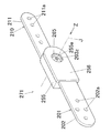
この角度調節器271は、上記第3実施形態の角度調節器171と同じく、複数の木製フレームを有する家具(例:ソファー)に主に用いられるものである。第1アーム201の取付け部202は板状であり、互いに連結される2個の木製フレームのうち一方のフレームに木ねじやボルト等の締結具で取り付けられる。第2アーム210の取付け部211は板状であり、他方のフレームに木ねじやボルト等の締結具で取り付けられる。そのため、各取付け部202、211には、締結具が挿通される挿通孔202a、211aが穿設されている。
Similar to the
また、この角度調節器271では、図17Bに示すように、巻締め部材205の個数は1個であり、また第1アーム201の外側板部203の個数は1個である。また、スペーサ部材208には軽量化のための貫通孔208zが穿設されている。
Moreover, in this
回転軸部213を有する回転板212は、第2アーム210とは別体に形成されている。図17Cに示すように、回転軸部213は巻締め部材205の巻締め部206の内側に配置され、これにより回転軸部213の外周面に巻締め部材205の巻締め部206が巻かれた状態となっている。同図において、230は回転軸部213の外周面と巻締め部206の内周面との接触部である。
The
図17Bに示すように、回転軸部213の先端部の中央部には、断面非円形状の嵌合孔260が回転軸部213の軸線方向に貫通して設けられている。本実施形態では、嵌合孔260の断面形状は正多角形状(詳述すると正六角形状)である。第2アーム210の取付け部211の基端部には、嵌合孔260に対応する断面非円形状の嵌合軸部262が一体回転可能に突設されている。本実施形態では、嵌合軸部262の断面形状は正多角形状(詳述すると正六角形状)である。
As shown in FIG. 17B, a
さらに、図17Bに示すように、この角度調節器271は、外ケース255と、該外ケース255用蓋板256と、巻締め部材205を側方から覆う内側サイドカバー板250と、を備えている。そして、図17B及び17Cに示すように、内側サイドカバー板250と巻締め部材205とスペーサ部材208と第1アーム201の外側板部203とが、第1リベット225及び第2リベット226を介して連結されている。さらに、これらが外ケース255内に収容されるとともに、外ケース255の開口部に蓋板256が装着されている。
Further, as shown in FIG. 17B, the
外ケース255には断面円形状の貫通孔255aが設けられるとともに、内側サイドカバー板250にも断面円形状の貫通孔250aが設けられている。そして、外ケース255の外側から第2アーム210の嵌合軸部262がこれらの貫通孔255a、250aに連通して挿通されるとともに、更に、嵌合軸部262が回転軸部213の嵌合孔260に着脱自在に嵌合されている。
The
蓋板256には断面円形状の貫通孔256aが設けられるとともに、第1アーム201の外側板部203にも断面円形状の貫通孔203zが設けられている。そして、これらの貫通孔256a、203zの内側において、蓋板256の外側から抜け止め用ビス265が嵌合軸部262の先端部に設けられたネジ孔263に複数のワッシャ(詳述するとスプリングワッシャ及び平ワッシャ)266を介して着脱自在に螺合されており、これにより、嵌合軸部262が嵌合孔260から離脱しないようになっている。
The
この角度調節器271において、各アームの取付け部にフレームを取り付ける際には、ビス265をネジ孔263から取り外し、嵌合軸部262を嵌合孔260から離脱させて第1アーム201と第2アーム210とを分離する。次いで、各アームの取付け部にフレームを木ねじやボルト等の締結具で取り付ける。このとき、両アーム201、210は分離されているから、その取付け作業を容易に行うことができる。その取付け作業が終了したら、嵌合軸部262を嵌合孔260に再度、嵌合させてビス265をネジ孔263に螺合させる。これにより、第1アーム201と第2アーム210とが互いに連結される。
In this
この角度調節器271によれば、第2アーム210の嵌合軸部262が回転軸部213の嵌合孔260に着脱自在に嵌合されているので、嵌合軸部262を嵌合孔260から離脱させ、次いで嵌合軸部262を嵌合孔260に対して回転させて嵌合孔260に再度、嵌合させることにより、第2アーム210の展開角度の調節可能範囲を維持したままで第2アーム210の展開開始角度及び展開終了角度を変更することができる。
According to the
以上で本発明の幾つかの実施形態について説明したが、本発明はこれらの実施形態に示したものに限定されるものではなく、本発明の要旨を変更しない範囲において様々に変更可能である。 Although several embodiments of the present invention have been described above, the present invention is not limited to those shown in these embodiments, and various modifications can be made without departing from the scope of the present invention.
例えば、上記実施形態では、角度調節器は座椅子の背フレームの傾倒角度調節器として用いられるものであるが、本発明では、角度調節器は座椅子のそれに用いられるものに限定されるものではなく、その他に、例えば、肘掛け付き椅子における肘掛けの角度調節器として用いられるものであっても良いし、フットレスト付き椅子におけるフットレストの角度調節器として用いられるものであっても良いし、机の天板の傾斜角調節器として用いられるものであっても良い。さらに、折り畳み式ベッドに用いられるものであっても良いし、液晶ディスプレイパネル、有機ELディスプレイパネルなどのパネルを支持するために支持アーム装置に用いられるものであっても良い。 For example, in the above embodiment, the angle adjuster is used as a tilt angle adjuster of the back frame of the seat chair, but in the present invention, the angle adjuster is limited to that used for the seat chair. In addition to this, for example, it may be used as an angle adjuster for an armrest in a chair with an armrest, or may be used as an angle adjuster for a footrest in a chair with a footrest, It may be used as a tilt angle adjuster for the top plate. Furthermore, it may be used for a folding bed, or may be used for a support arm device for supporting a panel such as a liquid crystal display panel or an organic EL display panel.
また本発明では、巻締め部材はバネ弾性を有するものであることが上記実施形態で説明したように特に望ましいが、バネ弾性を有しないものであることを排除するものではなく、例えば巻締め部材がチェーンで構成されることを排除するものではない。 Further, in the present invention, it is particularly desirable that the winding member has spring elasticity, as described in the above embodiment, but this does not exclude the fact that the winding member does not have spring elasticity. It is not excluded that is composed of chains.
また本発明は、本発明の技術的思想を用いて角度調節器について第1アームに対する第2アームの展開角度が段階的に調節されるように構成することを排除するものではない。 Further, the present invention does not exclude that the angle adjuster is configured so that the deployment angle of the second arm with respect to the first arm is adjusted stepwise using the technical idea of the present invention.
本発明は、家具類(例:リクライニング椅子、折り畳み式ベッド、折り畳み式ソファー)などに用いられる角度調節器及び該角度調節器を備えたリクライニング椅子に利用可能である。 The present invention is applicable to an angle adjuster used for furniture (eg, a reclining chair, a foldable bed, a foldable sofa) and the like and a reclining chair provided with the angle adjuster.
1:第1アーム
3:外側板部
5:巻締め部材
5a:巻締め部材の一端部
5b:巻締め部材の他端部
6:巻締め部
6c:巻締め部の内周面
8:スペーサ部材
8c:押付け部(解除手段)
8d:ストッパ部
9:隙間
10:第2アーム
12:回転板部(解除手段)
12a:第1押し部(解除手段)
12b:第2押し部(解除手段)
13:回転軸部
13a:回転軸部の外周面
15:解除手段
16:押圧部材(解除手段)
18:規制手段
19:規制部材(規制手段)
20:規制孔(規制手段)
25:第1リベット
26:第2リベット
30:接触部
40:金属素板
42:上カバー部材
43:下カバー部材
71、72:角度調節器
S:正回転方向
G:逆回転方向
SK:正回転方向の荷重
GK:逆回転方向の荷重
SM:正回転方向の摩擦力
GM:逆回転方向の摩擦力
P0:巻締め部材の巻締め部の中心位置
P1:第1枢着位置(第1固定位置)
P2:第2枢着位置(第2固定位置)
L1:第1距離
L2:第2距離
Q:回転軸部の軸心位置
U:緩め方向
V:巻締め方向
X:押圧位置
Y:非押圧位置
1: First arm 3: Outer plate portion 5: Winding
8d: Stopper portion 9: Clearance 10: Second arm 12: Rotating plate portion (release means)
12a: 1st pushing part (release means)
12b: 2nd pushing part (release means)
13: Rotating
18: Restriction means 19: Restriction member (regulation means)
20: Restriction hole (regulation means)
25: 1st rivet 26: 2nd rivet 30: Contact part 40: Metal base plate 42: Upper cover member 43:
P2: Second pivot position (second fixed position)
L1: First distance L2: Second distance Q: Axle center position U: Loosening direction V: Winding direction X: Pressing position Y: Non-pressing position
Claims (2)
回転軸部を備えた第2アームと、を具備し、
前記回転軸部は、前記第2アームに一体回転可能に設けられており、
前記巻締め部材の一端部及び他端部は前記第1アームに設けられており、
前記第1アームと前記第2アームとが、前記回転軸部の外周面に前記巻締め部材の巻締め部が巻かれた状態で前記第2アームが前記回転軸部を中心に前記第1アームに対して相対的に回転可能になるように連結されており、
前記第2アームの所定の回転方向の回転動作により前記回転軸部の外周面と前記巻締め部材の前記巻締め部の内周面との接触部に発生する前記所定の回転方向の摩擦力が、前記巻締め部材に作用することにより、前記第2アームの前記所定の回転方向の回転が阻止されるものとなされており、
前記巻締め部材はバネ弾性を有しており、
前記回転軸部の外周面に前記巻締め部材の前記巻締め部が巻かれた状態において、前記巻締め部材のバネ弾性力によって前記回転軸部の外周面が常時、巻き締められている角度調節器。 A first arm having a winding member;
A second arm having a rotating shaft portion,
The rotating shaft portion is provided to be rotatable integrally with the second arm,
One end and the other end of the tightening member are provided on the first arm,
The first arm and the second arm are configured such that the second arm is centered on the rotation shaft portion in a state where the winding tightening portion of the tightening member is wound on the outer peripheral surface of the rotation shaft portion. Connected to be rotatable relative to
The frictional force in the predetermined rotation direction generated at the contact portion between the outer peripheral surface of the rotating shaft portion and the inner peripheral surface of the winding tightening portion of the winding tightening member by the rotating operation of the second arm in the predetermined rotating direction. , By acting on the winding member, rotation of the second arm in the predetermined rotation direction is prevented ,
The winding member has spring elasticity,
Angle adjustment in which the outer peripheral surface of the rotating shaft portion is always tightened by the spring elastic force of the winding member in a state where the tightening portion of the tightening member is wound around the outer peripheral surface of the rotating shaft portion vessel.
Priority Applications (1)
| Application Number | Priority Date | Filing Date | Title |
|---|---|---|---|
| JP2013059314A JP6012521B2 (en) | 2013-03-22 | 2013-03-22 | Angle adjuster |
Applications Claiming Priority (1)
| Application Number | Priority Date | Filing Date | Title |
|---|---|---|---|
| JP2013059314A JP6012521B2 (en) | 2013-03-22 | 2013-03-22 | Angle adjuster |
Related Parent Applications (1)
| Application Number | Title | Priority Date | Filing Date |
|---|---|---|---|
| JP2012104700A Division JP5232317B1 (en) | 2012-05-01 | 2012-05-01 | Angle adjuster |
Publications (3)
| Publication Number | Publication Date |
|---|---|
| JP2013230354A JP2013230354A (en) | 2013-11-14 |
| JP2013230354A5 JP2013230354A5 (en) | 2015-06-25 |
| JP6012521B2 true JP6012521B2 (en) | 2016-10-25 |
Family
ID=49677366
Family Applications (1)
| Application Number | Title | Priority Date | Filing Date |
|---|---|---|---|
| JP2013059314A Active JP6012521B2 (en) | 2013-03-22 | 2013-03-22 | Angle adjuster |
Country Status (1)
| Country | Link |
|---|---|
| JP (1) | JP6012521B2 (en) |
Families Citing this family (1)
| Publication number | Priority date | Publication date | Assignee | Title |
|---|---|---|---|---|
| CN107920695B (en) * | 2015-06-12 | 2021-08-10 | 嘉利柴尔控股有限公司 | Bathing frame for children |
Family Cites Families (2)
| Publication number | Priority date | Publication date | Assignee | Title |
|---|---|---|---|---|
| DE1290833B (en) * | 1964-10-16 | 1969-03-13 | Keiper Recaro Gmbh Co | Articulated fitting for seats, especially motor vehicle seats |
| JPS58173352U (en) * | 1982-05-13 | 1983-11-19 | 池田物産株式会社 | Seat back tilt angle adjustment mechanism |
-
2013
- 2013-03-22 JP JP2013059314A patent/JP6012521B2/en active Active
Also Published As
| Publication number | Publication date |
|---|---|
| JP2013230354A (en) | 2013-11-14 |
Similar Documents
| Publication | Publication Date | Title |
|---|---|---|
| JP5232317B1 (en) | Angle adjuster | |
| EP2253246B1 (en) | Angle-adjustable hinge | |
| JP4021451B2 (en) | Height adjustment device for web guide of seat belt system | |
| US9341010B2 (en) | Furniture door position adjustment device for furniture hinge | |
| JP2002137714A (en) | Buckle device | |
| EP2805642B1 (en) | Angle-adjustable hinge | |
| US20130264858A1 (en) | Reclining device | |
| EP2805645A1 (en) | Sofa | |
| JP6012521B2 (en) | Angle adjuster | |
| JP5465410B2 (en) | Angle adjustment bracket | |
| CN107510280B (en) | Angle adjusting fitting | |
| EP3058850B1 (en) | Angular adjustment tool and sofa | |
| JP2014061175A (en) | Angle adjuster | |
| JP2015053970A (en) | Angle adjustment | |
| JP2015231490A (en) | Angle adjuster | |
| JP2009189391A (en) | Joint fitting and legless chair | |
| JP5109538B2 (en) | Vehicle seat rotation device | |
| KR20070117130A (en) | A back of a chair | |
| JP6830703B1 (en) | Angle adjuster and furniture using it | |
| JP4217806B2 (en) | Handle device | |
| JP5687781B2 (en) | Angle adjustment bracket | |
| US8205524B2 (en) | Torque limiting handle assembly | |
| JP3661560B2 (en) | Mounting structure of the spring unit in the chair back tilt mechanism | |
| JP2007143603A (en) | Seat reclining device | |
| JP5908999B2 (en) | Angle adjustment bracket |
Legal Events
| Date | Code | Title | Description |
|---|---|---|---|
| A521 | Request for written amendment filed |
Free format text: JAPANESE INTERMEDIATE CODE: A523 Effective date: 20150430 |
|
| A621 | Written request for application examination |
Free format text: JAPANESE INTERMEDIATE CODE: A621 Effective date: 20150430 |
|
| A977 | Report on retrieval |
Free format text: JAPANESE INTERMEDIATE CODE: A971007 Effective date: 20160329 |
|
| A131 | Notification of reasons for refusal |
Free format text: JAPANESE INTERMEDIATE CODE: A131 Effective date: 20160405 |
|
| A521 | Request for written amendment filed |
Free format text: JAPANESE INTERMEDIATE CODE: A523 Effective date: 20160603 |
|
| TRDD | Decision of grant or rejection written | ||
| A01 | Written decision to grant a patent or to grant a registration (utility model) |
Free format text: JAPANESE INTERMEDIATE CODE: A01 Effective date: 20160830 |
|
| A61 | First payment of annual fees (during grant procedure) |
Free format text: JAPANESE INTERMEDIATE CODE: A61 Effective date: 20160920 |
|
| R150 | Certificate of patent or registration of utility model |
Ref document number: 6012521 Country of ref document: JP Free format text: JAPANESE INTERMEDIATE CODE: R150 |
|
| RD02 | Notification of acceptance of power of attorney |
Free format text: JAPANESE INTERMEDIATE CODE: R3D02 |
|
| S111 | Request for change of ownership or part of ownership |
Free format text: JAPANESE INTERMEDIATE CODE: R313113 |
|
| R250 | Receipt of annual fees |
Free format text: JAPANESE INTERMEDIATE CODE: R250 |
|
| R350 | Written notification of registration of transfer |
Free format text: JAPANESE INTERMEDIATE CODE: R350 |
|
| R250 | Receipt of annual fees |
Free format text: JAPANESE INTERMEDIATE CODE: R250 |
|
| R250 | Receipt of annual fees |
Free format text: JAPANESE INTERMEDIATE CODE: R250 |
|
| R250 | Receipt of annual fees |
Free format text: JAPANESE INTERMEDIATE CODE: R250 |
|
| R250 | Receipt of annual fees |
Free format text: JAPANESE INTERMEDIATE CODE: R250 |
|
| R250 | Receipt of annual fees |
Free format text: JAPANESE INTERMEDIATE CODE: R250 |