JP3661560B2 - Mounting structure of the spring unit in the chair back tilt mechanism - Google Patents
Mounting structure of the spring unit in the chair back tilt mechanism Download PDFInfo
- Publication number
- JP3661560B2 JP3661560B2 JP2000126099A JP2000126099A JP3661560B2 JP 3661560 B2 JP3661560 B2 JP 3661560B2 JP 2000126099 A JP2000126099 A JP 2000126099A JP 2000126099 A JP2000126099 A JP 2000126099A JP 3661560 B2 JP3661560 B2 JP 3661560B2
- Authority
- JP
- Japan
- Prior art keywords
- stopper
- tension rod
- support member
- backrest
- spring unit
- Prior art date
- Legal status (The legal status is an assumption and is not a legal conclusion. Google has not performed a legal analysis and makes no representation as to the accuracy of the status listed.)
- Expired - Fee Related
Links
- 230000006835 compression Effects 0.000 claims description 30
- 238000007906 compression Methods 0.000 claims description 30
- 230000001105 regulatory effect Effects 0.000 claims description 11
- 238000003780 insertion Methods 0.000 claims description 8
- 230000037431 insertion Effects 0.000 claims description 8
- 210000002414 leg Anatomy 0.000 description 10
- 210000000078 claw Anatomy 0.000 description 4
- 230000000694 effects Effects 0.000 description 4
- 238000012986 modification Methods 0.000 description 4
- 230000004048 modification Effects 0.000 description 4
- 239000000463 material Substances 0.000 description 3
- 229920003002 synthetic resin Polymers 0.000 description 3
- 239000000057 synthetic resin Substances 0.000 description 3
- 238000000034 method Methods 0.000 description 2
- 230000000630 rising effect Effects 0.000 description 2
- 229920001875 Ebonite Polymers 0.000 description 1
- 229910000831 Steel Inorganic materials 0.000 description 1
- 239000006096 absorbing agent Substances 0.000 description 1
- 230000000903 blocking effect Effects 0.000 description 1
- 210000001217 buttock Anatomy 0.000 description 1
- 238000006116 polymerization reaction Methods 0.000 description 1
- 230000002265 prevention Effects 0.000 description 1
- 230000035939 shock Effects 0.000 description 1
- 239000010959 steel Substances 0.000 description 1
Images


Landscapes
- Chair Legs, Seat Parts, And Backrests (AREA)
- Chairs Characterized By Structure (AREA)
- Chairs For Special Purposes, Such As Reclining Chairs (AREA)
Description
【0001】
【発明の属する技術分野】
本発明は、椅子の背凭れ傾動機構におけるばねユニットの取付構造に係わり、更に詳しくは背凭れ部を前傾方向へ弾性付勢するためのばねユニットを所定部位に取付けるためのばねユニットの取付構造に関するものである。
【0002】
【従来の技術】
従来、座部に対して背凭れ部が前後傾動し、座部と背凭れ部との間に設けた強さが調節可能なばねユニットにて該背凭れ部の後傾動に対して弾性抵抗力を付与してなる椅子は公知である。
【0003】
ここで、前述の椅子に用いられる前記ばねユニットは、座部の下板に形成した小孔に、上方から上端に係止部を設けた軸体を挿通し、次いで背凭れ支持部材の中間部の開口に挿通し、該軸体の下方突出部に圧縮コイルばねを巻装するとともに、該軸体の下部にノブの回転に伴って回転するナット部材を螺合し、背凭れ支持部材とノブ又はナット部材の間に圧縮コイルばねを圧縮状態で保持した構造のものである。
【0004】
しかし、前述のばねユニットは、前記ナットの抜け止めのために、軸体の下端に螺孔を形成し、該螺孔に頭部がナットの螺孔径より大きいネジを螺着する必要があって加工及び部品コストが高くなるばかりでなく、前記ナットやネジを締めるときに、背凭れ傾動機構部を反転させる必要があるので組立コストも高く、更にばねユニットの部品が椅子を組み立てる前にはバラバラであるので部品管理や組立工数が多いといった欠点がある。
【0005】
【発明が解決しようとする課題】
そこで、本発明が前述の状況に鑑み、解決しようとするところは、脚部に取付けた取付体に対して背凭れ支持部材をばねユニットにて前傾方向へ弾性付勢する椅子の背凭れ傾動機構において、ばねユニット自体の組立てが容易且つ低コストであるとともに、背凭れ傾動機構へのばねユニットの取付作業が極めて簡単且つ短時間で行うことが可能な椅子の背凭れ傾動機構におけるばねユニットの取付構造を提供する点にある。
【0006】
【課題を解決するための手段】
本発明は、前述の課題解決のために、脚部に取付けた取付体に対して背凭れ支持部材をばねユニットにて前傾方向へ弾性付勢する椅子の背凭れ傾動機構において、前記ばねユニットは、ノブから延びたテンション杆を当止体に挿通するとともに、ノブと当止体間に圧縮コイルばねを介装し、前記テンション杆の先端に係止片を略T字形となるように形成してなり、前記取付体には前記係止片が通過可能な長形孔とそれに交叉する係合凹部からなる係止部を形成し、前記背凭れ支持部材には前記係止片が通過可能且つ前記当止体が通過不能な開口を形成し、前記テンション杆の先端部を開口と長形孔に挿通し且つ前記当止体を背凭れ支持部材の背面に当止した後、テンション杆を回転させて前記係止片を係合凹部に係合するとともに、前記長形孔内に規制体の一部を嵌合保持して前記テンション杆を回転止めしてなる椅子の背凭れ傾動機構におけるばねユニットの取付構造を構成した。
【0007】
ここで、前記規制体は、前記背凭れ支持部材の背面に係止し且つ前記開口を通して前記当止体に接触可能であるとともに、中心部に前記テンション杆を挿通する挿通孔を形成したフランジ部と、該フランジ部の挿通孔を挟んだ位置から延び前記テンション杆の両側に残る前記長形孔内に嵌入可能であるとともに、前記係止片の上端に係止可能な一対の嵌合片と、を有するものであることが好ましい。
【0008】
更に、前記規制体の両嵌合片の先端に、前記テンション杆の係止片を渡した状態で係止可能な凹溝を形成し、両嵌合片の凹溝に係止片を係止した状態で前記長形孔に下方から両嵌合片及び係止片を挿入可能となすことがより好ましい。
【0009】
そして、前記ばねユニットの当止体は、中心部に円形孔を形成するとともに、前記圧縮コイルばねの一端を当止し得る当止板と、二つ割り部材であり、重合面に前記テンション杆をスライド可能に挟持する縦溝を形成するとともに、下部外周に前記当止板の円形孔に接合するテーパー面を形成し且つ重合状態で上端が前記背凭れ支持部材の開口縁に当止可能である当止部材とからなり、更に前記当止板の周囲から延びた筒状カバー部と前記ノブとで前記圧縮コイルばねを外覆してなるものである。
【0010】
あるいは、前記ノブは少なくとも一端が閉塞板で閉塞された筒体であり、一端の閉塞板と、ノブ内部に回転不能且つ軸方向スライド可能に内装するとともに、前記テンション杆を螺合した可動板との間に圧縮コイルばねを介装したものであり、前記ばねユニットの当止体は、中心部に円形孔を形成した前記閉塞板と、二つ割り部材であり、重合面に前記テンション杆をスライド可能に挟持する縦溝を形成するとともに、下部外周に前記閉塞板の円形孔に接合するテーパー面を形成し且つ重合状態で上端が前記背凭れ支持部材の開口縁に当止可能である当止部材とからなるものである。
【0011】
【発明の実施の形態】
次に本発明の実施の形態を添付図面に基づき更に詳細に説明する。図1は本発明に係る椅子の全体斜視図、図2〜図10は椅子の機構部分の詳細図を示し、図中符号1は脚部、2は座部、3は背凭れ部、4はばねユニット、5は取付体、6は背凭れ支持部材、7は座支持部材をそれぞれ示している。
【0012】
本発明に係る椅子は、脚部1に座部2を回転可能に取付けるとともに、背凭れ部3を前後傾動可能に取付け且つ該背凭れ部3の動作に連動して座部2の後部を上下動可能となすとともに、前後スライド可能となし、そして一つのばねユニット4にて前記背凭れ部3の後傾動と座部2の後部の下動に対して弾性抵抗力を同時に付与したものである。
【0013】
つまり、本発明に係る椅子は、脚部1に取付けた取付体5の中央部下部に背凭れ支持部材6の下端部を第1枢着部8にて前後傾動可能に取付け、前記取付体5の上位に略水平に配した座支持部材7の前部を該取付体5の前部に前後スライド可能且つ上下揺動可能に連結するとともに、座支持部材7の後部と、前記背凭れ支持部材6の第1枢着部8とは異なる部分とを、第2枢着部9にて回動可能に連結し、前記取付体5の後部に対して背凭れ支持部材6を強さが調節可能なばねユニット4で前傾方向へ弾性付勢してなるものである。
【0014】
前記取付体5は、スチール板材をプレス加工によって一体成形したものであり、底板10から周囲が立ち上がった上方開放の箱状であり、少なくとも両側板11,11と底板10の後部に後方上方へ傾斜した傾斜部12を有し、上縁周囲には祖と向きに鍔部13を形成したものである。
【0015】
更に詳しくは、前記取付体5には、前記両側板11,11の前部に横長の開口14,14を形成するとともに、該開口14の直上の鍔部13を切起して当止片15をそれぞれ両側に突設し、また両側板11,11の後部に鍔部13にわたって切欠部16,16を形成している。また、前記底板10の中央部やや後方寄り位置には、脚部1に立設したガスシリンダー17の上端部を取付けるための円形孔18を形成するとともに、取付体5の内部で前記底板10とは間隔を置いて固着した固定部材19の中央部にも円形孔20を形成し、両円形孔18,20を貫通するように上方が縮径したテーパー状の固定筒21を固着し、該固定筒21に前記ガスシリンダー17の先細上端部を嵌着するようになっている。更に、前記底板10の下面で中央部やや後方寄り位置には、支持部材22を固着し、該支持部材22の両側縁に下向きに形成した支持板23,23には前記第1枢着部8を構成する支軸24を挿通するための支持孔25,25を形成している。尚、前記支持部材22に設けた支持孔25,25の位置は、前記ガスシリンダー17よりも若干前方である。
【0016】
前記背凭れ支持部材6は、後部に背凭れ杆26を連設若しくは一体形成した部材であり、背凭れ杆26の上部には図示しないクッション体を取付けて前記背凭れ部3を構成するものである。前記背凭れ支持部材6の前部は斜め前下方へ延び、背面を構成する主板27の両側縁に上方へ向いた連結板28,28を有し、該連結板28,28の中央部側には上方へ略三角形状となして幅広となっており、該連結板28の前下部には前記支軸24を挿通するための支持孔29を形成するとともに、後上部には前記第2枢着部9を構成する支軸30を挿通するための連結孔31を形成している。また、前記背凭れ支持部材6の主板27の前下端部には、前記ガスシリンダー17を受け入れる前方開放した切欠開口32を形成している。
【0017】
前記座支持部材7は、上面板33の両側に側面板34,34を下方へ延設した断面略コ字形の部材であり、該上面板33の上部に図示しないクッション体を取付けて前記座部2を構成するものである。前記座支持部材7は、前記側面板34,34間に取付体5を受け入れることが可能で且つ前記背凭れ支持部材6の両連結板28,28間に受け入れられることが可能な横幅を有し、該側面板34,34の前部下方へ張り出した部分に、前記取付体5の開口14,14に前後動可能に遊嵌するガイド軸35を取付けるための通孔36,36を形成するとともに、側面板34,34の後部に前記支軸30を受け入れる下方開放した切欠溝37,37を形成している。更に詳しくは、前記ガイド軸35には、円筒状の合成樹脂製スリーブ38が被嵌されており、前記取付体5の当止片15の上端に当該座支持部材7の上面板33が載支された状態で、前記開口14内でスリーブ38が自由に前後移動できるように該開口14の上下幅を設定している。尚、前記ガイド軸35は両側面板34,34からそれぞれ突設した突起であっても良い。また、前記切欠溝37は前記支軸30を挿通するのに必要最小限な幅の導入部37Aと、支軸30に被嵌した円筒状の合成樹脂製スリーブ39を回転可能に嵌合する軸受部37Bとからなっている。そして、図4に示した最大負荷状態、即ち着座して背凭れ部3に凭れ掛かって前記背凭れ支持部材6が最も後傾して前記座支持部材7の後部が後方へ移動しながら沈んだ状態で、前記スリーブ39又は該スリーブ39が支軸30の両端部のみに設けた場合には支軸30が、前記固定部材19の上面に取付けた緩衝板40に当止するようになっている。
【0018】
そして、前記脚部1のガスシリンダー17の上端に前記取付体5を取付けた状態で、前記背凭れ支持部材6を取付体5の後部下方からあてがい、前記支持部材22の支持板23,23を両連結板28,28間に位置させ、支持板23,23の支持孔25,25と連結板28,28の支持孔29,29とに前記支軸24を挿通して連結する。この際、それぞれ両側部で両支持孔25,29に合成樹脂製のスリーブ41を嵌挿し、該スリーブ41に前記支軸24を挿通して回動時の金属音が発生しないようにしている。また、前記前記背凭れ支持部材6が最も後傾した場合に、それ以上の後傾を制限するために、前記支持板23,23の下端部にストッパー片42を突設し、前記背凭れ支持部材6の主板27の両側先端が該ストッパー片42に当止するようになっている。
【0019】
それから、前記座支持部材7を取付体5に被せて、前部は前記当止片15,15に上面板33を載支するとともに、前記ガイド軸35を開口14,14を貫通させて取付け、後部は前記背凭れ支持部材6の連結孔31,31に貫通させた支軸30を前記切欠溝37,37内に受け入れるとともに、支軸30に外嵌したスリーブ39を切欠溝37の軸受部37Bに嵌合して上下方向へ抜け止め状態で連結する。つまり、前記座支持部材7の前部は取付体5の前部に前後スライド可能且つ上下揺動可能に連結されている。
【0020】
前記ガイド軸35と開口14との係合部、第1枢着部8を構成する支軸24、第2枢着部9を構成する支軸30とは、逆三角形の頂点に位置し、図3に示した状態から背凭れ支持部材6が後方へ傾動すると、その動作に伴って座支持部材7の後部が下動するとともに、座支持部材7が全体的に後方へ移動して図4に示した状態となる。この場合、前記当止片15が上面板33の下面に接触した状態を維持しながら、前記ガイド軸35が開口14内を後方へ移動することになる。
【0021】
次に、本発明に係る椅子の背凭れ傾動機構におけるばねユニットの取付構造について説明する。ここで、前記背凭れ支持部材6を前傾方向へ弾性付勢するためのばねユニット4は、図2〜図10に詳しく示されているように、取付体5の底板10に対して背凭れ支持部材6の主板27を引き付ける方向に弾性力を付与し、またその弾性力の強さを調節できるものである。また、当該ばねユニット4は、一つの構成部品として組み立てた後、所定位置に簡単に装着できるにも係わらず、容易に外れないようになしたことを特徴としている。
【0022】
つまり、前記ばねユニット4は、脚部1に取付けた取付体5の後部に対して背凭れ支持部材6を前傾方向へ弾性付勢するものであり、ノブ43から延びたテンション杆44を当止体45に挿通するとともに、ノブ43と当止体45間に圧縮コイルばね46を介装し、前記テンション杆44の先端に係止片47を略T字形となるように形成してなり、前記取付体5には前記係止片47が通過可能な長形孔49とそれに交叉する係合凹部50からなる係止部48を形成し、前記背凭れ支持部材6には前記係止片47が通過可能且つ前記当止体45が通過不能な開口51を形成し、前記テンション杆44の先端部を開口51と長形孔49に挿通し且つ前記当止体45を背凭れ支持部材6の背面に当止した後、テンション杆44を回転させて前記係止片47を係合凹部50に係合するとともに、前記長形孔49内に規制体52の一部を嵌合保持して前記テンション杆44を回転止めしてなるものである。
【0023】
更に詳しくは、前記ばねユニット4の当止体45は、中心部に前記係止片47が通過可能な円形孔53を形成するとともに、前記圧縮コイルばね46の一端を当止し得る当止板54と、二つ割り部材であり、重合面に前記テンション杆44をスライド可能に挟持する縦溝56を形成するとともに、下部外周に前記当止板54の円形孔53に接合するテーパー面57を形成し且つ重合状態で上端が前記背凭れ支持部材6の開口51の縁部に当止可能である当止部材55,55とから構成されている。ここで、前記二つ割り当止部材55,55は、硬質ゴム等の弾性変形可能な素材で成形し、重合状態で上端部に前記取付体5の長形孔49に遊挿可能である。更に、前記当止板54には、その周囲から延びた筒状カバー部58を有し、該カバー部58と前記ノブ43とで前記圧縮コイルばね46を外覆している。前記カバー部58は、前記ノブ43を内挿できる内径を有し、常にノブ43の上部が内挿された状態となっている。尚、本実施形態では、前記円形孔53は、テーパー面57に面接合するテーパー孔で形成している。
【0024】
そして、前記テンション杆44の下部に形成した螺軸部59に小判型のフランジ付きナット部材60を螺合するとともに、該ナット部材60を前記ノブ43に回り止め状態で保持し、該ノブ43を回転することにより、弾性付勢力を調節できるようになっている。尚、前記ナット部材60を螺軸部59に螺合した後に、該螺軸部59の先端をカシメることにより抜けないようにしている。更に、前記ノブ43は、上方へ開放した筒状部材であり、中央部に前記ナット部材60を保持する円筒形状の保持部61を形成するとともに、その周囲に前記圧縮コイルばね46の一端を保持する環状凹部62を形成している。また、前記保持部61の上面には前記係止片47が通過可能で前記ナット部材60のフランジ部63が通過不能な装着孔64を形成している。更に、前記保持部61の開口部はキャップ65を嵌着して閉鎖している。
【0025】
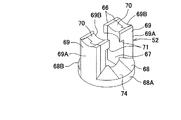
前記規制体52は、本実施形態では同一形状で互いに180度回転させた状態で嵌合して一体化する二つ割りの規制小体66,66から構成されている。ここで、前記規制体52の二つ割り構造は、特に限定されないが、図5〜図7に示した規制小体66で構成すれば、互いに無理嵌め状態で一体化できるので好ましく、また予め一端に係止片47が固定され且つ他端に抜け止め状態でナット部材60が螺合されている前記テンション杆44の軸部に外挿するためには必要であるが、ナット部材60を後で螺合して組み立てる場合には、図11に示したように一体成形したものであっても良いのである。つまり、図7に示した本実施形態の規制体52は、前記背凭れ支持部材6の背面に係止し且つ前記開口51を通して前記当止体45に接触可能であるとともに、中心部に前記テンション杆44を挿通する挿通孔67を形成したフランジ部68と、該フランジ部68の挿通孔67を挟んだ位置から延び前記テンション杆44の両側に残る前記長形孔49内に嵌入可能であるとともに、前記係止片47の上端に係止可能な一対の嵌合片69,69とを有するものである。
【0026】
更に詳しくは、前記規制体52の両嵌合片69,69の先端に、前記テンション杆44の係止片47を渡した状態で係止可能な凹溝70,70を形成し、両嵌合片69,69の凹溝70,70に係止片47を係止した状態で前記長形孔49に下方から両嵌合片69,69及び係止片47を共に挿入可能となしている。また、前記両嵌合片69,69の先端部内側には、当該嵌合片69,69の間に落とし込んだ係止片47の上端に係止できるように係止爪部71,71を突設している。また、前記テンション杆44の係止片47は、棒体の上面を水平面でカットした断面倒D字形となして、前記嵌合片69,69の間に落とし込み易く、しかも係止爪部71,71を確実に係止できるようにしている。
【0027】
前述の規制体52を構成する規制小体66は、図5及び図6に示すように、下部に半割のフランジ部68Aを有し、該フランジ部68Aから両嵌合片69A,69Aを立設するとともに、両嵌合片69A,69A間に対応するフランジ部68Aの内縁部には前記挿通孔67を形成する凹部67Aを形成し、更に一方の嵌合片69Aの上部内側に係止爪部71Aを突設している。そして、一方の嵌合片69Aの外側一側に嵌合凹部72Aを上下に形成するとともに、他方の嵌合片69Aの内側他側に前記嵌合凹部72Aと凹凸嵌合し得る形状の嵌合凸部73Aを形成している。このように「A」を付した一方の規制小体66と、図6に示すように[B」を付した他方の規制小体66とを、前記テンション杆44の軸部を挟んで両側から互いに嵌合し、それぞれのフランジ部68A,68Bで前記フランジ部68を形成し、内外に接合された嵌合片69A,69Bで前記嵌合片69を形成するのである。また、前記フランジ部68の上面は周囲が薄肉となった円錐形状とし、前記係合凹部50の下面に対応する部分には凹溝74を形成している。
【0028】
そこで、前記ばねユニット4を組み立てるには、図2に示すように、先ず螺軸部59にナット部材60を螺合したテンション杆44を、係止片47側からノブ43の装着孔64に下方より挿通し、ナット部材60を保持部61の内部に嵌合する。次に、前記係止片47側から圧縮コイルばね46をテンション杆44に巻装し、その一端を環状凹部62に嵌合した後、前記カバー部58を有する当止板54の円形孔53に係止片47側からテンション杆44を挿通し、圧縮コイルばね46の一端を当止板54に当止する。それから、テーパー状の円形孔53の外部に、同じくテーパー面57を有する二つ割りの当止部材55,55をその縦溝56,56でテンション杆44の軸部を挟み込んで装着し、前記圧縮コイルばね46を圧縮しながら、当止部材55,55と係止片47との間に前記規制体52を装着するとともに、両嵌合片69,69の凹溝70,70に係止片47を係止する。この状態で、圧縮コイルばね46に加えていた圧縮力を除いても、ばねユニット4はそのままの状態を維持する。これで、ばねユニット4の組み立てと所定部位への装着前の設定を完了する。
【0029】
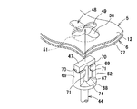
そして、図8に示すように、前記テンション杆44の係止片47を、規制体52の両嵌合片69,69とともに前記背凭れ支持部材6の開口51に下方より挿入し、更に取付体5の長形孔49に挿入し、前記係止片47を取付体5の底板10後部の傾斜部12上面に出現させる。それから、前記係止片47をテンション杆44を中心として強制的に回転させて該係止片47を凹溝70,70から外せば、前記圧縮コイルばね46の弾性復元力によって、該係止片47が両嵌合片69,69間に落ち込み、前記係合凹部50に係合すると同時に係止爪部71,71によって抜止状態となる(図9及び図10参照)。ここで、抜止状態とは、前記規制体52の両嵌合片69,69が取付体5の長形孔49に嵌合した状態を維持することを意味し、両嵌合片69,69で前記係止片47の中央部を挟んで該係止片47の回転を強制的に制限することにより、該係止片47が長形孔49から抜けることがなくなるのである。
【0030】
次に、本発明に係る椅子の動作について説明する。図3に示した無負荷状態、即ち着座しない初期状態では、前記ばねユニット4の圧縮コイルばね46の弾性付勢力によって背凭れ支持部材6の主板27が取付体5の底板10後部の傾斜部12に最も接近し、当止体45の当止部材55と底板10が接触している。また、取付体5の傾斜部12と当止部材55との間には、背凭れ支持部材6の開口51を貫通した規制体52のフランジ部68が挟まれている。それから、座部2に着座して背凭れ部3に凭れ掛かかると、前記背凭れ支持部材7は第1枢着部8を中心に後傾するとともに、それに伴って前記座支持部材7の後部が若干後方へ変位しながら沈み、遂には図4に示した最大負荷状態となって、前記スリーブ39の下端が前記取付体5の固定部材19の上面に設けた緩衝体40に当接する。つまり、前記背凭れ支持部材6と座支持部材7の動作変化の両極端を規定している。
【0031】
また、前記二つ割り当止部材55,55の両縦溝56,56でテンション杆44の上部を挟持し、しかもテーパー面57,57を当止板54のテーパー状円形孔53に嵌合していることから、両縦溝56,56とテンション杆44との間には常に摺動摩擦力が働き、背凭れ支持部材6の前後方向の傾動動作時にその摩擦力が制動力となって急激な変化を規制するのである。更に、この制動力は、背凭れ支持部材6が後傾するにつれて圧縮コイルばね46の弾性力が大きくなって両縦溝56,56をテンション杆44に押し付ける力が増大するので徐々に大きくなる。従って、背凭れ支持部材6の後傾に対する抵抗力は、圧縮コイルばね46の弾性力と、両縦溝56,56とテンション杆44との間に生じる制動力との和になる。一方、着座者が後傾状態から立起状態に起き上がる際には、背凭れ支持部材6に作用する後傾方向の負荷が急激に小さくなって、圧縮コイルばね46の弾性力によって背凭れ支持部材6が初期状態に速やかに復帰しようとするが、前述の両縦溝56,56とテンション杆44との間に生じる制動力によってその復帰動作が緩やかになる。
【0032】
また、図11に示した変形例は、前述の如く前記ばねユニット4の規制体52の構造が一体構造のものである。この場合、前記ばねユニット4の組立て手順が異なり、先ず前記テンション杆44の螺軸部59から規制体52を挿入し、それから当止部材55,55を組付けながら、同じく螺軸部59から圧縮コイルばね46とノブ43の装着孔64を次々に通し、圧縮コイルばね46を圧縮しながらナット部材60を螺軸部59に螺合する。その後に、ばねユニット4を所定位置に装着する方法は前述と同様である。
【0033】
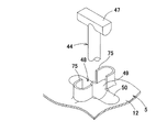
また、図12に示した変形例は、前記規制体52を用いることなく、係合凹部50に係合した係止片47の回転を規制するものであり、前記長形孔49を傾斜部12にプレス成形する際に該傾斜部12の板材をバーリング加工することよってその周囲に立起部75,75を形成したものである。そして、前記立起部75,75の立ち上がり縁で前記係止片47の回転を規制するのである。
【0034】
また、図13には、ばねユニット4の変形例を示してある。このばねユニット4は、前記ノブ43は少なくとも一端が閉塞板76で閉塞された筒体であり、一端の閉塞板76と、ノブ43内部に回転不能且つ軸方向スライド可能に内装するとともに、前記テンション杆44の螺軸部59に螺合したナット部材60を相対回転不能に嵌合した可動板77との間に圧縮コイルばね46を介装したものであり、前記ばねユニット4の当止体45は、中心部に円形孔53を形成した前記閉塞板76と、二つ割り部材であり、重合面に前記テンション杆44をスライド可能に挟持する縦溝56を形成するとともに、下部外周に前記閉塞板76の円形孔53に接合するテーパー面57を形成し且つ重合状態で上端が前記背凭れ支持部材6の開口51の口縁部に当止可能である当止部材55,55とから構成されたものである。この場合も、前記圧縮コイルばね46は外部に露出することがないので、外観的にもスッキリとしたものになる。
【0035】
【発明の効果】
以上にしてなる請求項1に係る発明の椅子の背凭れ傾動機構におけるばねユニットの取付構造は、脚部に取付けた取付体に対して背凭れ支持部材をばねユニットにて前傾方向へ弾性付勢する椅子の背凭れ傾動機構において、前記ばねユニットは、ノブから延びたテンション杆を当止体に挿通するとともに、ノブと当止体間に圧縮コイルばねを介装し、前記テンション杆の先端に係止片を略T字形となるように形成してなり、前記取付体には前記係止片が通過可能な長形孔とそれに交叉する係合凹部からなる係止部を形成し、前記背凭れ支持部材には前記係止片が通過可能且つ前記当止体が通過不能な開口を形成し、前記テンション杆の先端部を開口と長形孔に挿通し且つ前記当止体を背凭れ支持部材の背面に当止した後、テンション杆を回転させて前記係止片を係合凹部に係合するとともに、前記長形孔内に規制体の一部を嵌合保持して前記テンション杆を回転止めしてなるので、背凭れ傾動機構へのばねユニットの取付作業が極めて簡単且つ短時間で行うことができるにも係わらず、前記係止片が係合した係合凹部から外れる恐れがないのである。
【0036】
請求項2によれば、前記効果に加えて、規制体の両嵌合片が長形孔内に嵌合し、両嵌合片で係止片の中央部を挟んで、該係止片の回転を強制的に制限することができるので、係止片が係合した係合凹部から外れることが全くないのである。
【0037】
請求項3によれば、前記効果に加えて、背凭れ傾動機構へのばねユニットの取付作業が極めて簡単であるにもかかわらず、背凭れ傾動機構にばねユニットを装着した状態が極めて安定であり、不意に分解する恐れもないのである。
【0038】
請求項4及び5によれば、前記効果に加えて、圧縮コイルばねが外部に露出しないので、ばねユニットの外観性がスッキリしたものとなるばかりでなく、誤って圧縮コイルばねに指を挟まれることを未然に防止できる。
【図面の簡単な説明】
【図1】本発明に係る椅子の全体斜視図である。
【図2】背凭れ支持部材と座支持部材の傾動機構及びばねユニットを示す分解断面図である。
【図3】無負荷状態の要部の縦断面図である。
【図4】最大負荷状態の要部の縦断面図である。
【図5】規制体を構成する規制小体を示し、(a)は平面図、(b)は側面図、(c)は(a)のX−X線断面図である。
【図6】規制体の分解斜視図である。
【図7】同じく規制体の斜視図である。
【図8】ばねユニットを背凭れ支持部材と取付体に装着する状態を示す部分斜視図である。
【図9】同じくばねユニットを背凭れ支持部材と取付体に装着した状態を示す部分斜視図である。
【図10】同じくばねユニットを背凭れ支持部材と取付体に装着した状態を示す部分平面図である。
【図11】規制体の変形例を示す斜視図である。
【図12】係止片の外れ防止構造の他の例を示す部分斜視図である。
【図13】ばねユニットの変形例を示す要部の縦断面図である。
【符号の説明】
1 脚部 2 座部
3 背凭れ部 4 ばねユニット
5 取付体 6 背凭れ支持部材
7 座支持部材 8 第1枢着部
9 第2枢着部 10 底板
11 側板 12 傾斜部
13 鍔部 14 開口
15 当止片 16 切欠部
17 ガスシリンダー 18 円形孔
19 固定部材 20 円形孔
21 固定筒 22 支持部材
23 支持板 24 支軸
26 背凭れ杆 27 主板
28 連結板 29 支持孔
30 支軸 31 連結孔
32 切欠開口 33 上面板
34 側面板 35 ガイド軸
36 通孔 37 切欠溝
37A 導入部 37B 軸受部
38 スリーブ 39 スリーブ
40 緩衝体 41 スリーブ
42 ストッパー片 43 ノブ
44 テンション杆 45 当止体
47 係止片 48 係止部
49 長形孔 50 係合凹部
51 開口 52 規制体
53 円形孔 54 当止板
55 当止部材 56 縦溝
57 テーパー面 58 カバー部
59 螺軸部 60 ナット部材
61 保持部 62 環状凹部
63 フランジ部 64 装着孔
65 キャップ 66 規制小体
67 挿通孔 67A 凹部
68 フランジ部 69 嵌合片
70 凹溝 71 係止爪部
72A 嵌合凹部 73A 嵌合凸部
74 凹溝 75 立起部
76 閉塞板 77 可動板[0001]
BACKGROUND OF THE INVENTION
The present invention relates to a spring unit mounting structure in a backrest tilting mechanism of a chair, and more specifically, a spring unit mounting structure for mounting a spring unit for elastically biasing a backrest portion in a forward tilt direction to a predetermined portion. It is about.
[0002]
[Prior art]
Conventionally, the backrest part tilts back and forth with respect to the seat part, and an elastic resistance force against the back tilt of the backrest part by a spring unit that can adjust the strength provided between the seat part and the backrest part. A chair provided with is known.
[0003]
Here, the spring unit used in the above-mentioned chair is inserted into a small hole formed in the lower plate of the seat portion through a shaft body provided with a locking portion from the upper end to the upper end, and then the middle portion of the back support member A compression coil spring is wound around the lower projecting portion of the shaft body, and a nut member that rotates with the rotation of the knob is screwed to the lower portion of the shaft body so that the back support member and the knob Alternatively, the compression coil spring is held in a compressed state between the nut members.
[0004]
However, in order to prevent the nut from coming off, the above-described spring unit needs to be formed with a screw hole at the lower end of the shaft body, and a screw whose head is larger than the screw hole diameter of the nut must be screwed into the screw hole. Not only does the processing and parts cost increase, but the assembly cost is high because it is necessary to reverse the back tilting mechanism when tightening the nuts and screws, and the parts of the spring unit are separated before assembling the chair. Therefore, there are disadvantages such as many parts management and assembly man-hours.
[0005]
[Problems to be solved by the invention]
Therefore, in view of the above-described situation, the present invention intends to solve the problem of the backrest tilting of the chair that elastically biases the backrest support member in the forward tilt direction by the spring unit with respect to the attachment body attached to the leg portion. In the mechanism, the assembly of the spring unit itself is easy and low cost, and the attachment of the spring unit to the back tilting mechanism is extremely simple and can be performed in a short time. It is in providing a mounting structure.
[0006]
[Means for Solving the Problems]
In order to solve the above-described problem, the present invention provides a chair backrest tilting mechanism in which a backrest support member is elastically biased forwardly by a spring unit with respect to a mounting body attached to a leg portion. The tension rod extending from the knob is inserted into the stopper body, and a compression coil spring is interposed between the knob and the stopper body, and the locking piece is formed in a substantially T-shape at the tip of the tension rod. The mounting body is formed with an elongated hole through which the engagement piece can pass and an engagement recess intersecting with the elongated hole, and the back support member can pass the engagement piece. In addition, an opening through which the stopper body cannot pass is formed, the tip end portion of the tension rod is inserted into the opening and the elongated hole, and the stopper body is seated against the back of the support member, and then the tension rod is attached. Rotate to engage the locking piece with the engaging recess, and A part of the regulating member and fitted and held to constitute a mounting structure of the spring unit in the backrest tilt mechanism of the chair formed by stopping rotating the tension rod within.
[0007]
Here, the restricting body engages with the back surface of the backrest supporting member and can contact the stopper body through the opening, and has a flange portion in which an insertion hole for inserting the tension rod is formed in the center portion. And a pair of fitting pieces that can be fitted into the elongated holes extending from a position sandwiching the insertion hole of the flange portion and remain on both sides of the tension rod, and that can be latched to the upper end of the locking piece; It is preferable that it has.
[0008]
Furthermore, a recessed groove that can be locked in a state where the locking piece of the tension rod is passed is formed at the tip of both fitting pieces of the restricting body, and the locking piece is locked in the recessed groove of both fitting pieces. In this state, it is more preferable that both fitting pieces and locking pieces can be inserted into the elongated hole from below.
[0009]
The stopper of the spring unit is formed with a circular hole in the center, a stopper plate that can stop one end of the compression coil spring, and a split member, and slides the tension rod on the overlapping surface. A vertical groove that can be sandwiched is formed, a tapered surface that is joined to the circular hole of the stopper plate is formed on the outer periphery of the lower portion, and the upper end can be stopped against the opening edge of the backrest support member in a superposed state. The compression coil spring is covered with a tubular cover portion extending from the periphery of the stopper plate and the knob.
[0010]
Alternatively, the knob is a cylindrical body having at least one end closed by a closing plate, and is provided with a closing plate at one end and a movable plate in which the tension rod is screwed, and the knob is mounted in a non-rotatable and axially slidable manner. A compression coil spring is interposed in between, and the stopper of the spring unit is the closing plate formed with a circular hole in the center and a split member, and the tension rod can slide on the overlapping surface The stopper member is formed with a longitudinal groove sandwiched between them and a tapered surface joined to the circular hole of the closing plate on the outer periphery of the lower part, and the upper end can stop against the opening edge of the backrest support member in a superposed state It consists of
[0011]
DETAILED DESCRIPTION OF THE INVENTION
Next, embodiments of the present invention will be described in more detail with reference to the accompanying drawings. FIG. 1 is an overall perspective view of a chair according to the present invention, FIGS. 2 to 10 are detailed views of a mechanism part of the chair, in which 1 is a leg, 2 is a seat, 3 is a backrest, 4 is The spring unit, 5 is a mounting body, 6 is a back support member, and 7 is a seat support member.
[0012]
In the chair according to the present invention, the
[0013]
That is, in the chair according to the present invention, the lower end portion of the
[0014]
The
[0015]
More specifically, the
[0016]
The
[0017]
The
[0018]
Then, with the
[0019]
Then, the
[0020]
The engaging portion between the
[0021]
Next, a mounting structure of the spring unit in the chair back tilting mechanism according to the present invention will be described. Here, the
[0022]
That is, the
[0023]
More specifically, the
[0024]
Then, an oval
[0025]
In the present embodiment, the restricting
[0026]
More specifically,
[0027]
As shown in FIGS. 5 and 6, the
[0028]
Therefore, in order to assemble the
[0029]
Then, as shown in FIG. 8, the locking
[0030]
Next, the operation of the chair according to the present invention will be described. In the unloaded state shown in FIG. 3, i.e., the initial state in which the seat is not seated, the
[0031]
Further, the upper portion of the
[0032]
Further, in the modification shown in FIG. 11, the structure of the regulating
[0033]
Further, the modification shown in FIG. 12 regulates the rotation of the locking
[0034]
FIG. 13 shows a modification of the
[0035]
【The invention's effect】
In the chair backrest tilting mechanism according to the first aspect of the present invention, the spring unit mounting structure is configured such that the backrest support member is elastically attached in the forward tilt direction by the spring unit to the mounting body mounted on the leg. In the chair back tilting mechanism, the spring unit inserts a tension rod extending from the knob into the stopper, and a compression coil spring is interposed between the knob and the stopper, and the tip of the tension rod The locking piece is formed so as to be substantially T-shaped, and the mounting body is formed with a locking portion consisting of a long hole through which the locking piece can pass and an engagement recess intersecting with the elongated hole, The back support member is formed with an opening through which the locking piece can pass and the stopper cannot pass, the tip end of the tension rod is inserted into the opening and the elongated hole, and the stopper is backed. Rotate the tension rod after stopping against the back of the support member The engaging piece is engaged with the engaging recess and a part of the regulating body is fitted and held in the elongated hole to stop the rotation of the tension rod. Although the attaching operation of the spring unit can be carried out extremely easily and in a short time, there is no fear that the engaging piece will be disengaged from the engaging recess.
[0036]
According to
[0037]
According to the third aspect, in addition to the above effect, the state in which the spring unit is mounted on the backrest tilting mechanism is extremely stable even though the mounting operation of the spring unit to the backrest tilting mechanism is extremely simple. There is no danger of unintentional disassembly.
[0038]
According to
[Brief description of the drawings]
FIG. 1 is an overall perspective view of a chair according to the present invention.
FIG. 2 is an exploded cross-sectional view showing a tilting mechanism and a spring unit of a backrest support member and a seat support member.
FIG. 3 is a longitudinal sectional view of a main part in an unloaded state.
FIG. 4 is a longitudinal sectional view of a main part in a maximum load state.
5A and 5B show a regulation body constituting the regulation body, in which FIG. 5A is a plan view, FIG. 5B is a side view, and FIG. 5C is a sectional view taken along line XX of FIG.
FIG. 6 is an exploded perspective view of a regulating body.
FIG. 7 is a perspective view of the regulating body.
FIG. 8 is a partial perspective view showing a state in which the spring unit is mounted on the back support member and the attachment body.
FIG. 9 is a partial perspective view showing a state in which the spring unit is similarly mounted on the back support member and the attachment body.
FIG. 10 is a partial plan view showing a state in which the spring unit is similarly mounted on the back support member and the attachment body.
FIG. 11 is a perspective view showing a modified example of the regulating body.
FIG. 12 is a partial perspective view showing another example of the locking piece disengagement prevention structure.
FIG. 13 is a longitudinal sectional view of a main part showing a modification of the spring unit.
[Explanation of symbols]
1
3 Backrest 4 Spring unit
5 Mounting
7
9
11
13
15 Stopping
17
19 Fixing
21
23
26 Backrest 27 Main plate
28 Connecting
30
32
34
36 through
38
40
42
44
47
49
51
53
55 Stopping
57
59
61 holding
63
65
67
68
70
72A Fitting
74
76
Claims (5)
Priority Applications (1)
| Application Number | Priority Date | Filing Date | Title |
|---|---|---|---|
| JP2000126099A JP3661560B2 (en) | 2000-04-26 | 2000-04-26 | Mounting structure of the spring unit in the chair back tilt mechanism |
Applications Claiming Priority (1)
| Application Number | Priority Date | Filing Date | Title |
|---|---|---|---|
| JP2000126099A JP3661560B2 (en) | 2000-04-26 | 2000-04-26 | Mounting structure of the spring unit in the chair back tilt mechanism |
Publications (2)
| Publication Number | Publication Date |
|---|---|
| JP2001299488A JP2001299488A (en) | 2001-10-30 |
| JP3661560B2 true JP3661560B2 (en) | 2005-06-15 |
Family
ID=18635939
Family Applications (1)
| Application Number | Title | Priority Date | Filing Date |
|---|---|---|---|
| JP2000126099A Expired - Fee Related JP3661560B2 (en) | 2000-04-26 | 2000-04-26 | Mounting structure of the spring unit in the chair back tilt mechanism |
Country Status (1)
| Country | Link |
|---|---|
| JP (1) | JP3661560B2 (en) |
Families Citing this family (3)
| Publication number | Priority date | Publication date | Assignee | Title |
|---|---|---|---|---|
| JP2009273679A (en) * | 2008-05-15 | 2009-11-26 | Itoki Corp | Seat plate angle adjusting device of chair |
| KR100899580B1 (en) | 2008-11-05 | 2009-05-27 | (주)대륜엠유씨 | Assembly structure of chair elastic adjustment cap |
| CN119037886A (en) * | 2024-08-12 | 2024-11-29 | 江苏美凤力医疗科技有限公司 | Kit for detecting cell activity |
-
2000
- 2000-04-26 JP JP2000126099A patent/JP3661560B2/en not_active Expired - Fee Related
Also Published As
| Publication number | Publication date |
|---|---|
| JP2001299488A (en) | 2001-10-30 |
Similar Documents
| Publication | Publication Date | Title |
|---|---|---|
| RU2762644C2 (en) | Rotary fittings and item of furniture | |
| JPH0552726B2 (en) | ||
| US7334841B2 (en) | Angle adjustment mechanism for lumbar support of chair backrest | |
| US6672670B2 (en) | Pivoting armrest | |
| JP3661560B2 (en) | Mounting structure of the spring unit in the chair back tilt mechanism | |
| JPS6291335A (en) | Seat sliding device | |
| JP3359862B2 (en) | Locking device | |
| KR20200003988A (en) | The tilting chair | |
| KR20190135813A (en) | Rotation apparatus for back-rest of chair | |
| JP2003299548A (en) | Armrest mechanism and furniture with armrest including same | |
| KR101543553B1 (en) | Table with folding-up type chair | |
| JP3994649B2 (en) | Chair back tilting device | |
| US7735924B2 (en) | Positioning device for chair | |
| WO2006001914A1 (en) | Locking roller for an article of furniture | |
| JP4451549B2 (en) | Seating table | |
| JP4126847B2 (en) | Mounting structure of the spring unit in the chair back tilt mechanism | |
| JP4383907B2 (en) | Chair armrest equipment | |
| JP4908826B2 (en) | Reclining chair | |
| JP3689789B2 (en) | Chair | |
| JP4750535B2 (en) | Backrest locking device in reclining chair | |
| JP7650143B2 (en) | Folding chair | |
| JP3334461B2 (en) | Chair bearing structure | |
| KR101538031B1 (en) | The chair that have a variable armrest | |
| JP2005131234A (en) | Armrest device of chair | |
| JP5884428B2 (en) | Chair back pivoting device |
Legal Events
| Date | Code | Title | Description |
|---|---|---|---|
| A977 | Report on retrieval |
Free format text: JAPANESE INTERMEDIATE CODE: A971007 Effective date: 20050217 |
|
| TRDD | Decision of grant or rejection written | ||
| A01 | Written decision to grant a patent or to grant a registration (utility model) |
Free format text: JAPANESE INTERMEDIATE CODE: A01 Effective date: 20050301 |
|
| A61 | First payment of annual fees (during grant procedure) |
Free format text: JAPANESE INTERMEDIATE CODE: A61 Effective date: 20050314 |
|
| R150 | Certificate of patent or registration of utility model |
Free format text: JAPANESE INTERMEDIATE CODE: R150 |
|
| S533 | Written request for registration of change of name |
Free format text: JAPANESE INTERMEDIATE CODE: R313533 |
|
| R350 | Written notification of registration of transfer |
Free format text: JAPANESE INTERMEDIATE CODE: R350 |
|
| FPAY | Renewal fee payment (event date is renewal date of database) |
Free format text: PAYMENT UNTIL: 20090401 Year of fee payment: 4 |
|
| FPAY | Renewal fee payment (event date is renewal date of database) |
Free format text: PAYMENT UNTIL: 20090401 Year of fee payment: 4 |
|
| FPAY | Renewal fee payment (event date is renewal date of database) |
Free format text: PAYMENT UNTIL: 20100401 Year of fee payment: 5 |
|
| FPAY | Renewal fee payment (event date is renewal date of database) |
Free format text: PAYMENT UNTIL: 20110401 Year of fee payment: 6 |
|
| FPAY | Renewal fee payment (event date is renewal date of database) |
Free format text: PAYMENT UNTIL: 20130401 Year of fee payment: 8 |
|
| FPAY | Renewal fee payment (event date is renewal date of database) |
Free format text: PAYMENT UNTIL: 20140401 Year of fee payment: 9 |
|
| R250 | Receipt of annual fees |
Free format text: JAPANESE INTERMEDIATE CODE: R250 |
|
| LAPS | Cancellation because of no payment of annual fees |