JP6009628B2 - Chair - Google Patents
Chair Download PDFInfo
- Publication number
- JP6009628B2 JP6009628B2 JP2015138269A JP2015138269A JP6009628B2 JP 6009628 B2 JP6009628 B2 JP 6009628B2 JP 2015138269 A JP2015138269 A JP 2015138269A JP 2015138269 A JP2015138269 A JP 2015138269A JP 6009628 B2 JP6009628 B2 JP 6009628B2
- Authority
- JP
- Japan
- Prior art keywords
- outer shell
- seat
- shell
- inner shell
- slide
- Prior art date
- Legal status (The legal status is an assumption and is not a legal conclusion. Google has not performed a legal analysis and makes no representation as to the accuracy of the status listed.)
- Active
Links
Images


Description
本願発明は、椅子に関するものである。 The present invention is related to a chair.
椅子において、座の前後長さ(前端の奥行き)を調節する技術として、例えば特許文献1〜3に開示されているように、座の前部を下側に巻き込む方式が提案されている。これらの従来技術では、座の前部を変形許容部と成して、変形許容部の前端を左右横長のフロントバーに固定し、フロントバーを前後動させることにより、変形許容部を巻き込んだり伸ばしたりしている。フロントバーの左右両端部には後ろ向きに延びるサイドバーが固定されており、サイドバーは、受け部材で前後スライド自在に支持されている。 In the chair, as a technique for adjusting the longitudinal length of the seat (depth of the front end), for example, as disclosed in Patent Documents 1 to 3, a method of winding the front portion of the seat downward has been proposed. In these conventional techniques, the front part of the seat is formed as a deformation-permitting part, the front end of the deformation-permitting part is fixed to a horizontally long front bar, and the front bar is moved back and forth so that the deformation-permitting part is rolled up or stretched. It is. Side bars extending rearward are fixed to the left and right ends of the front bar, and the side bars are supported by a receiving member so as to be slidable back and forth.
座の前後長さを調節する操作方法としては、人が手で座の前端部に掴んで前後に押し引きしたり、或いは、別に設けた操作具でサイドバーを前後動させたりすることになるが、人が着座した状態では人の体圧がサイドバーに掛かることにより、着座した状態のままで前後長さを調節しにくくなり、そこで、座の前後長さを変えるに当たっては腰を浮かせた状態にせねばならないことがあり、このため、座の前後長さの調節(奥行き調節)が面倒であるという問題があった。 As an operation method for adjusting the front / rear length of the seat, a person grasps the front end of the seat with his / her hand and pushes / pulls forward / backward, or moves the sidebar back and forth with a separate operation tool. However, when the person is seated, the body pressure is applied to the sidebar, making it difficult to adjust the front and back length while sitting, so the waist was lifted when changing the front and back length of the seat. Therefore , there is a problem that adjustment of the length of the seat (depth adjustment) is troublesome.
また、座は着座した人の身体を支えるものであるから、その全体にわたって高い支持強度を有すべきであるが、従来は、変形許容部はその前端がフロントバーで支持されているに過ぎないため、身体の支持強度や支持安定性が必ずしも十分でないと言える。更に、人は、着座した状態で大腿部を座の前端部に強く突っ張らせることがあるが、従来のように座の前端(変形許容部の前端)をフンロトバーに固定した構造では、フンロトバーで大腿部を突き上げる現象が生じて、座り心地が悪くなるおそれもあった。 In addition, since the seat supports the body of the person who is seated, the seat should have a high support strength throughout, but conventionally, the front end of the deformable portion is only supported by the front bar. Therefore, it can be said that the support strength and support stability of the body are not necessarily sufficient. In addition, a person may strongly stretch the thigh to the front end of the seat while sitting, but in the conventional structure where the front end of the seat (the front end of the deformation allowing portion) is fixed to the funnel, A phenomenon of pushing up the thigh has occurred, and there is a possibility that the sitting comfort may deteriorate.
本願発明はこのような現状に鑑み成されたものであり、座の前後長さ(前端の奥行き)を調節できる椅子において、支持強度や座り心地の向上、前後長さ調節の容易性等を図ることを目的とするものである。 The present invention has been made in view of such a current situation, and in a chair capable of adjusting the longitudinal length of the seat (depth of the front end), the support strength and the sitting comfort are improved , the ease of adjusting the longitudinal length, etc. It is for the purpose.
本願発明の椅子は、座インナーシェルにクッションを張った座と、前記座インナーシェルを下から支持する座アウターシェルとを有しており、前記座インナーシェルの前部を下向きに巻き込み可能な変形許容部と成すことにより、前記座の前後長さを調節可能になっている。 The chair of the present invention has a seat in which a cushion is stretched on a seat inner shell, and a seat outer shell that supports the seat inner shell from below, and the front inner portion of the seat inner shell can be wound downward. by forming a allowing portion, it has a longitudinal length of the seat adjustable capacity.
そして、前記座アウターシェルは、当該座アウターシェルの少なくとも後ろ側半分を構成する固定アウターシェルと、前記固定アウターシェルの手前に突出した部分を有するスライドアウターシェルとで構成されており、前記座インナーシェルのうち前記変形許容部よりも後ろの部分は、前記固定アウターシェルに前後相対動不能に取り付けられており、前記座インナーシェルの前部は、前記スライドアウターシェルが後退動すると下向きに
巻き込まれるように曲がり変形し、スライドアウターシェルが前進すると伸びるように変形するようになっている。
Then, the pre-Symbol seat outer shell, a fixed outer shell constituting at least the back half of the seat outer shell is constituted by a slide outer shell having a portion protruding in front of the fixed outer shell, said seat A portion of the inner shell behind the deformation-permitting portion is attached to the fixed outer shell so as not to move forward and backward, and the front portion of the seat inner shell faces downward when the slide outer shell moves backward.
It bends and deforms so as to be caught, and deforms to extend when the slide outer shell moves forward.
更に、前記スライドアウターシェルは、左右両側部に設けたレール部によって前記固定アウターシェルに前後スライド自在に保持されており、前記スライドアウターシェルのうち前記左右レール部の間の部位は、前記座インナーシェルを広い範囲にわたって支持し得るように面的な広がりを持っており、前記面的な広がりを持っている部分は、前進しきった状態でもその後部が前記固定アウターシェルと平面視で重なっている。 Furthermore, the slide outer shell is slidably held back and forth by the fixed outer shell by rail portions provided on both left and right side portions, and a portion of the slide outer shell between the left and right rail portions is the seat inner The shell has a wide area so that the shell can be supported over a wide range, and the portion having the wide area overlaps the fixed outer shell in a plan view even when it is fully advanced. .
請求項2の発明は、請求項1において、前記座インナーシェルの変形許容部には左右横長のスリットが前後多列に形成されており、前記スリットを挟んで前後に分かれた部分を側面視凸形のブリッジ部で連結することにより、前記変形許容部を前後方向に大きく伸ばし変形させることが許容されている。 The invention according to claim 2, Oite to claim 1, wherein the seat is in the deformable portion of the inner shell lateral oblong slits are formed before and after the multi-row, side portions which is divided into front and rear sides of the said slit It is allowed to greatly extend and deform the deformation permission portion in the front-rear direction by connecting with a bridge portion having a convex shape .
本願発明では、スライドアウターシェルを前後動させることで座の前後長さが変わるが、固定アウターシェルは少なくとも後ろ半分を構成しているため、例えば、人が背中を背もたれに当てた通常の着座状態で、着座した人の体圧の大部分を固定アウターシェルで支持できる。そして、着座者の体圧を主として前記固定アウターシェルで支持した状態で、座インナーシェルでスライドアウターシェルが上から押圧されることはないため、人が普通に腰掛けた状態では、スライドアウターシェルに荷重が作用することは全く又は殆どなく、その結果、着座した状態のままで座の前後長さを調節することができる。このため、操作性に優れていてユーザーフレンドリーである。 In the present invention, the longitudinal length of the seat changes by moving the slide outer shell back and forth, but since the fixed outer shell constitutes at least the rear half, for example , a normal sitting state in which a person hits his back against the backrest Thus, most of the body pressure of the seated person can be supported by the fixed outer shell. Since the slide outer shell is not pressed from above by the seat inner shell while the body pressure of the seated person is mainly supported by the fixed outer shell , the slide outer shell is There is no or almost no load acting, so that the longitudinal length of the seat can be adjusted while seated. For this reason, it is excellent in operability and user-friendly.
また、本願発明では、スライドアウターシェルは面的な広がりを持っているため、着座者の体圧が座の前部に作用しても、座インナーシェルは過度に変形することなくスライドアウターシェルでしっかりと支持される。このため、支持強度に優れている。また、座インナーシェルが着座した人の体圧で沈み込んでスライドアウターシェルに当たった場合、座インナーシェルはスライドアウターシェルによって広い面積で支持されるため、座インナーシェルが局部的に大きく変形して人の大腿部に突き上げ感を与えるような不具合はなく、このため座り心地に優れている。つまり、強度や座り心地を犠牲にすることなく、座の前後長さを調節できる。 Further, in the present invention, the slide outer shell has a wide area, so that even if the body pressure of the seated person acts on the front part of the seat, the seat inner shell does not deform excessively. Firmly supported. For this reason, it is excellent in support strength. In addition, when the seat inner shell sinks due to the body pressure of the seated person and hits the slide outer shell, the seat inner shell is supported by a wide area by the slide outer shell, so the seat inner shell is greatly deformed locally. Therefore, there is no problem that gives a feeling of pushing up to a person's thigh, so that the sitting comfort is excellent. That is, the longitudinal length of the seat can be adjusted without sacrificing strength or sitting comfort.
請求項2の構成を採用すると、座インナーシェルの変形許容部は前後方向に伸び変形するため、当該変形許容部を折り返すように変形させることを軽い力で容易に実現できる。つまり、スライドアウターシェルを後退させて変形許容部を曲げ変形させるにおいて、曲がりの曲率を大きくした状態で折り返す(巻き込む)ことができるため、折り返し(巻き込み)に対する抵抗が小さく、このため座の長さ調節を軽い力で行えるのである。 If the structure of Claim 2 is employ | adopted, since the deformation | transformation permission part of a seat inner shell will extend and deform | transform in the front-back direction, it can implement | achieve easily and deform | transform so that the said deformation | transformation permission part may be turned back. That is, when the slide outer shell is retracted to bend and deform the deformable portion, it can be folded back (involved) with a large curvature, so the resistance to folding (winding) is small, and therefore the length of the seat Adjustment can be done with light force.
次に、本願発明の実施形態を図面に基づいて説明する。以下の説明では方向を特定するため「前後」「左右」の文言を使用するが、この前後左右の文言は、着座した人を基準にしている。正面視方向は着座した人と対峙した方向であり、従って、正面視での左右と着座した人から見た左右とは逆になる。 Next, an embodiment of the present invention will be described with reference to the drawings. While using the word "longitudinal", "lateral" to identify the direction in the following description, the front and rear left and right wording is based on the person seated. The front view direction is the direction facing the seated person, and therefore the left and right in the front view are opposite to the left and right viewed from the seated person.
(1).椅子の概略
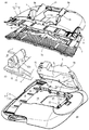
まず、椅子の概要を主として図1〜図3に基づいて説明する。本実施形態は事務用等に多用されている回転椅子に適用しており、椅子は、脚支柱1(図1(C)参照)のみを表示している脚装置と、脚支柱1の上端に固定したベース2と、ベース2の上に配置した座3と、着座した人がもたれ掛かり得る背もたれ4とを有している。ベース2は上向きに開口した箱状に形成されている。座3の平面視形状は、4つのコーナー部を丸めた略四角形に形成されている。
(1). Outline of Chair First, an outline of a chair will be described mainly with reference to FIGS. This embodiment is applied to a swivel chair that is frequently used for office work and the like, and the chair is provided with a leg device displaying only the leg support 1 (see FIG. 1C) and the upper end of the leg support 1. It has a fixed base 2, a
例えば図2に示すように、ベース2の上に金属板製の中間金具(座受け金具)5が配置されており、この中間金具5に、座部の一部を構成する樹脂製の座アウターシェル6が取り付けられている。中間金具5を使用せずに、座アウターシェル6をベース2に連結することも可能である。
For example, as shown in FIG. 2, an intermediate metal fitting (seat receiving metal fitting) 5 made of a metal plate is disposed on the base 2, and a resin seat outer that forms a part of the seat portion is disposed on the
座3は、樹脂製の座インナーシェル(座板)7とその上面に重ね配置した座クッション材8とを有している。座クッション材8は、クロス等の表皮材(図示せず)で上から覆われている。座アウターシェル6は、中間金具5に固定された固定アウターシェル9と、その手前に突出したスライドアウターシェル10とで構成されており、スライドアウターシェル10は、固定アウターシェル9に前後動自在に取り付けられている。
The
また、座インナーシェル7のうち前側寄り部位は、側面視で下向きに容易に曲がり変形する変形許容部7cになっており、変形許容部7cの前端部がスライドアウターシェル10の前端部に連結されている。このため、スライドアウターシェル10を前後スライドさせると座インナーシェル7の変形許容部7cが前向きに伸びたり下向きに巻き込まれたりする。これにより、座3の前後長さ(或いは座3の前端位置)を調節できる。
Further, a portion closer to the front side of the seat
例えば図2に示すように、ベース2に、第1背フレーム11が後傾動自在に連結されていると共に、第1背フレーム11にはその後ろに位置した第2背フレーム12が固定されており、第2背フレーム12に背もたれ4が取り付けられている。例えば図2に示すように、第1背フレーム11は、ベース2の外側位置で前向きに延びるアーム部11aを有しており、左右アーム部11aの前端部が左右横長の第1軸13でベース2に連結されている。従って、背もたれ4は第1軸13の軸心回りに傾動する。
For example, as shown in FIG. 2, the base 2, together with the
本実施形態の椅子は、背もたれ4の後傾に連動して座3が後退しつつ後傾するシンクロタイプの椅子であり、そこで、図2から理解できるように、中間金具5の前部をベース2に設けた受け部材14に前後動自在に装着する一方、中間金具5の後部は、第1背フレーム11に上向き突設したブラケット部15に左右横長の第2軸16で連結されている。ベース2の内部には、背もたれ4の後傾動を弾性的に支持する反力ユニットや、背もたれ4の傾動を制御するロック用ガスシリンダ等が配置されているが、本願発明との直接の関係はないので、説明は省略する。
The chair according to the present embodiment is a synchro-type chair in which the
(2).中間金具と座アウターシェルとの関係
以下、主として図4以降の図面を参照して各部位の詳細を説明する。まず、中間金具5と座アウターシェル6との関係を説明する。例えば図3に示すように、中間金具5は概ね平面視四角形に近い形状であり、上板5aと左右側板5bとを有している。第2軸16は側板5bに貫通している。
(2) Relationship between the intermediate metal fitting and the seat outer shell Details of each part will be described below mainly with reference to FIG. 4 and subsequent drawings. First, the relationship between the intermediate |
図4に示すように、固定アウターシェル9には、中間金具5にすっぽり嵌まり込む凹所18が形成されている。そして、中間金具5の上面の前端に、左右一対の前向きストッパー部19を設けている一方、固定アウターシェル9における凹所18の前端部には、前向きストッパー部19が後ろから嵌まるトンネル形の受け部20を一体に形成している。
As shown in FIG. 4, the fixed
更に、中間金具5における上板5aの後端部に、左右横長で角形のロック穴21を空けている一方、固定アウターシェル9における凹所18の後端部に、ロック穴21に嵌まるロック爪22を下向きに突設している。ロック爪22は、弾性変形してからロック穴21に嵌まり込む。これにより、固定アウターシェル9は中間金具5に抜け不能に取り付けられる。つまり、固定アウターシェル9を、中間金具5にワンタッチ的に取り付けることができる。第2軸16は固定アウターシェル9の凹所18に入り込んでいるため、スナップリング等の部材を使用しなくても抜け止めすることができる。
Further, a left and right laterally long
(3).座インナーシェル
座インナーシェル7はPP等の樹脂を材料にした成形品であり、例えば図6,7に明示するように、着座者の体圧が強く作用するメイン支持部7aと、メイン支持部7aの後ろに位置したリア支持部7bと、メイン支持部7aの手前に位置した既述の変形許容部7cとで構成されている。大雑把には、メイン支持部7aは前後長さのうちの半分弱を占め、リア支持部7bと変形許容部7cとは、それぞれ前後長さの1/4強程度の範囲を占めている。
(3). Seat Inner Shell The seat
例えば図6から理解できるように、座インナーシェル7は、正面視では上向き凹状に緩く湾曲しており、縦断側面視では、リア支持部7bが後ろに行くにしたがって高さが高くなるように緩く傾斜している。また、リア支持部7bの上面には、剛性を高くするため、縦横に延びるリブの群を上向きに突設している。
For example, as can be understood from FIG. 6, the seat
図7(A)に明示するように、座インナーシェル7のメイン支持部7aには、左右中間部に位置して前後に長いセンタースリット24の群と、その外側に形成された平面視弧状の中間スリット25の群と、中間スリット25の外側に位置して前後方向に長く伸びるサイドスリット26の群とが形成されている。かつ、メイン支持部7aとリア支持部7bとは左右側部のみが連結されていて、両者の間には左右横長の抜き溝27が形成されている。このため、メイン支持部7aは、着座者の体圧で下向きに伸び変形することが許容されている。
As clearly shown in FIG. 7A, the
例えば図6,7に示すように、座インナーシェル7の変形許容部7cには、横長のフロントスリット28が左右方向に3列で前後方向に多列(多段)に形成されており、これらフロントスリット28の群の存在により、変形許容部7cは、側面視で直線状に延びた姿勢から下向きに巻き込まれて折り返された姿勢に容易に変形することが許容されている。
For example, as shown in FIGS. 6 and 7, the
変形許容部7cの左右中間部と左右端部とには、図8(A)に示すように、側面視逆U形のブリッジ部29が形成されており、フロントスリット28を挟んで前後に分断された帯板状の部分はブリッジ部29で繋がっている。この逆U形のブリッジ部29の存在により、変形許容部7cは前後方向に大きく引き伸ばすことが可能になるため、巻き込み変形させることを抵抗なく確実に行える。従って、ブリッジ部29は伸長部と呼ぶことも可能である。なお、左右外側に位置したフロントスリット28は、変形許容部7cの側方に開口している。
As shown in FIG. 8 (A), a reverse
図3に示すように、クッション8のうち変形許容部7cに重なる部分は、他の部分に比べてやや薄くなっている。このため、クッション8の前部は容易に変形する。本実施形態のクッション8は成形品であるが、シート材のカット品を使用することも可能である。
As shown in FIG. 3, the portion of the
(4).座アウターシェル
座アウターシェル6を構成する固定アウターシェル9とスライドアウターシェル10とは、PP等の樹脂を素材にした成形品である。例えば図8(A)から理解できるように、固定アウターシェル9の前端は、座インナーシェル7における変形許容部7cの後部まで延びている(なお、図8(A)ではスリットは省略している。)。すなわち、固定アウターシェル9は、平面視において、座インナーシェル7のメイン支持部7a及びリア支持部7bの全体に重なると共に、座インナーシェル7における変形許容部7cの後部に部分的に重なる前後長さになっている。
(4). Seat outer shell The fixed
例えば図6から把握できるように、固定アウターシェル9は、正面で上向きに凹となるように緩く湾曲しており、後部は後ろ上がりに傾斜している。また、固定アウターシェル9の上面には、剛性を高めるために多数のリブが形成されている。固定アウターシェル9には、座インナーシェル7のメイン支持部7aが大きく沈み込むことを許容するため、抜き穴30が形成されている。
For example, as can be understood from FIG. 6, the fixed
例えば図6に示すように、スライドアウターシェル10は、固定アウターシェル9と略同じ左右横幅で面的な広がりを持つ基部10aと、基部10aの左右両側部から後ろ向きに突出したアーム部10bとを有している。基部10aは、前進させ切った状態でも後部は常に固定アウターシェル9に上から重なっており、後退させ切ると、基部10aの殆ど全体が固定アウターシェル9に重なる。アーム部10bは、常に固定アウターシェル9に上から重なっている。
For example, as shown in FIG. 6, the slide
スライドアウターシェル10の基部10aは基本的には板状であり(格子状でもよい)、上面には、補強用のリブが縦横に延びるように形成されている。そして、図6や図9(A)等に示すように、固定アウターシェル9の前端寄り部位に、頭を有する正面視T型の第1ガイド突起31を複数個突設している一方、スライドアウターシェル10の基部10aには、第1ガイド突起31が抜け不能で前後動自在に嵌まる前後長手のガイド長穴32を形成している。第1ガイド突起31とガイド長穴32とにより、第1ガイド手段が構成されている。第1ガイド突起31とガイド長穴32とは、左右方向に飛び飛びに4個ずつ形成されているが、個数や位置は任意に設定できる。
The
図6から理解できるように、各ガイド長穴32の後端部は、第1ガイド突起31の頭が嵌脱する広幅部32aになっている。このため、広幅部32aの箇所からガイド長穴32を第1ガイド突起31に嵌め込み、次いで、スライドアウターシェル10を後ろにスライドさせることにより、スライドアウターシェル10の基部10aは、固定アウターシェル10に抜け不能に保持される。
As can be understood from FIG. 6, the rear end portion of each
図9(B)(図6も参照)に示すように、スライドアウターシェル10のアーム部10bには、正断面視で下向きと上向きとに開口したクランク形で前後長手のガイド溝33が形成されている一方、固定アウターシェル9には、ガイド溝33に抜け不能に嵌まる略逆L形の第2ガイド突起34を一体に設けている。第2ガイド突起34とガイド溝33とは第2ガイド手段の一例を構成している。ガイド溝33には、下向き開口位置と上向き開口位置とを左右にずらすことにより、左右外向きに突出した支持部33aが形成されている。他方、第2ガイド突起34には、支持部33aの上に位置する内向き鉤部34a形成している。図12に示すように、ガイド溝33の後端部は、第2ガイド突起34の嵌め込みを許容するための広幅部33bになっている。
As shown in FIG. 9B (see also FIG. 6), the
図9,図10(C)に示すように、アーム部10bの下端には細幅の凸レール部35が形成されている一方、固定アウターシェル9には、凸レール部35がスライド自在に嵌まる凹レール部36が形成されており、これらレール部35,36が嵌まり合っていることにより、スライドアウターシェル10の左右位置が規制されている。凸レール部35は固定アウターシェル9の前端近くまで延びており、凹レール部36は、スライドアウターシェル10の前端近くまで延びている。
As shown in FIGS . 9 and 10C , a narrow
(5).座インナーシェルと座アウターシェルとの関係
座インナーシェル7は、座アウターシェル6の固定アウターシェル9とスライドアウターシェル10との両方に連結されている。この点を次に説明する。
(5) Relationship between seat inner shell and seat outer shell The seat
図6や図10(B)に示すように、固定アウターシェル9のうち左右両側縁寄りの部位でかつ略後半部には、前後に長いレール状のサイド支持部(サイド突条)38を形成しており、このサイド支持部38に、座インナーシェル7の支持リブ39が載っている。また、図10(B)に示すように、座インナーシェル7におけるメイン支持部7aのうち、支持リブ39の外側には水平状の段部40が形成されており、段部40の下側にスライドアウターシェル10のアーム部10bが配置されていると共に、段部40の内側壁の部位に内向きのストッパー片41を形成している。ストッパー片41は、上下に開口した抜き穴42で三方から囲われている(抜き穴42に三方から露出している。)。
As shown in FIG. 6 and FIG. 10 (B), rail-shaped side support portions (side protrusions) 38 that are long in the front and rear directions are formed in a portion near the left and right side edges of the fixed
そして、固定アウターシェル9の突条38に、ストッパー片41に上から被さる抑止片43を一体に設けている。すなわち、座インナーシェル7におけるメイン支持部7aの左右両端部は内向き移動不能に保持されており、このため、メイン支持部7aは、着座した人の荷重によって下向きに沈むように変形する。また、メイン支持部7aの左右両側部はサイド支持部38で下降不能に保持されているため、人が着座しても、スライドアウターシェル10のアーム部10bが座インナーシェル7のメイン支持部7aで下向きに押されることはない。従って、着座した状態で、スライドアウターシェル10のアーム部10bを容易に前後スライドさせ得る。
The
抜き穴42はストッパー片41の後方にはみ出ており、このため、座インナーシェル7を所定位置よりもやや手前に位置させてから固定アウターシェル9に重ねることにより、抑止片43を抜き穴42の後部に嵌め込むことができる。その状態で座インナーシェル7を後ろにずらすと、抑止片43がストッパー片41の上に位置する。
The punching
図10(C)に示すように、座インナーシェル7におけるメイン支持部7aの左右両側端部には、スライドアウターシェル10のアーム部10bに向いて内向き突出した支持片44を、前後方向に隔てて複数個形成している。支持片44は、表皮材を取り付けるためのものであるが、座インナーシェル7の支持機能を保持させることも可能である。なお、座インナーシェル7の左右縁部が内向きにずれ移動することを阻止するサイドリブを別に設けてもよい。
As shown in FIG. 10 (C),
図10(A)に示すように、固定アウターシェル9の左右後部に、上部が二股に形成された鉤形のリア係合爪45を設けている一方、座インナーシェル7のリア支持部7bには、リア係合爪45に上から嵌まり係合するリア係合穴46を形成している。このリア係合穴46も、座インナーシェル7を固定アウターシェル9に重ねてから後ろにずらすことにより、リア係合爪45に係合する。
As shown in FIG. 10 (A), the left and right rear portion of the fixed
図8(D)に示すように、座インナーシェル7におけるリア支持部7bの左右中間部には、前端を自由端として下向きに突出させたセンター係止片47を設けている一方、固定アウターシェル9には、センター係止片47が前向き動不能に嵌まるセンター受け部48を凹み形成している。センター係止片47は、その付け根を除いた3方がスリットで囲われており、このため、センター係止片47は、付け根を支点にして上下に回動し得る。また、センター受け部48には穴49が開口している。従って、センター係止片47は、例えばドライバーのような道具で上向きに突き上げることで、センター受け部48から離脱させることができる。
As shown in FIG. 8D, a
図7に示すように、固定アウターシェル9のうちセンター受け部48の左右外側の部位に、平面視四角形のサイド係合部49を形成し、このサイド係合部49に、座インナーシェル7のリア支持部7bに設けたサイド係合穴50が嵌まっている。これにより、座インナーシェル7の後ろ向き移動が規制されている。結局、座インナーシェル7は、センター係止片47とサイド係合部49とで前後ずれ不能に保持されている。
As shown in FIG. 7, a
サイド係合部49の箇所に、中間金具5に取り付けるためのロック爪22(図4も参照)を設けている。ロック爪22には、上向きに突出する指掛け片22aを設けている。このため、座3を取り外して指掛け片22aを手前に引くことで、ロック爪22を中間金具5から係合解除できる。
A lock claw 22 (see also FIG. 4) for attaching to the
座インナーシェル7の前端部の連結構造は、図8(B)に示している。すなわち、座インナーシェル7における変形許容部7cのうち中心線を挟んだ左右両側の2カ所に、左右の下向きブラケット部片53を介して支軸54を一体に形成する一方、スライドアウターシェル10の前端には、支軸54が上から嵌まる軸受け部55を一体に設けている。支軸54と軸受け部55とは相対回転し得る。
Connecting structure of the front end portion of the seat
従って、スライドアウターシェル10を後退させると変形許容部7cの前端は後ろに引かれる。このため、変形許容部7cは、折り返されたような状態で下方に巻き込まれる。これにより、座3の前端位置を変更して前後長さ(前端の奥行き)を調節できる。支軸54及び軸受け部55の対の配置位置は左右2カ所には限らず、中間部と左右両側との3カ所に設けるなど、個数と配置位置は任意に設定できる。また、支軸54をスライドアウターシェル10に設けて、軸受け部55を座インナーシェル7の変形許容部7cに設けることも可能である。更に、他の連結手段を採用してもよい。
Thus, the front end of the
図8(C)に示すように、座インナーシェル7における変形許容部7cの前端には、後ろ向きに突出したフロントストッパー56を設けている。これは、座クッション8を覆う表皮材を取り付けるためのものである。
As shown in FIG. 8 (C), the front end of the
(6).座の長さ調節(奥行き調節)操作機構
次に、座3の前後座長さ調節の操作装置を、主として図11,12に基づいて説明する。例えば図12(B)に示すように、操作装置は、スライドアウターシェル10の右側部に前後動自在に装着した指当てレバー58と、指当てレバー58の前後動によって左右スライドするロック部材59と、ロック部材59をロック姿勢に付勢するばね(圧縮コイルばね)60とを有する。指当てレバー58とロック部材59とは樹脂製である。
(6). Seat length adjustment (depth adjusting) operation mechanism Next, the operating device of the front and rear chair adjustment of the
図12(A)(C)に明瞭に示すように、スライドアウターシェル10の左右側部の下面は、内側に向けて低くなるように傾斜しており、この傾斜した下面に底面がフラットな凹所61を形成し、この凹所61に、指当てレバー58が前後動自在に配置されている。指当てレバー58は、凹所61の底面に重なる上板58aと、この上板58aから下向きに突出した摘まみ部58bとを有しており、上板58aに、スライドアウターシェル10の上に露出する正面視T形の係合突起63を一体に形成している。スライドアウターシェル10には、係合突起63が抜け不能に嵌まる前後長手の取り付け穴64を形成している。取り付け穴64の前端には、係合突起63が嵌脱自在な幅広部64aを形成している。
As clearly shown in FIGS. 12A and 12C, the lower surfaces of the left and right side portions of the slide
ロック部材59は左右長手のロッド状の形態であり、スライドアウターシェル10の下面に設けた左右長手のガイド溝65にスライド自在に嵌まっている。ガイド溝65と凹所61とは、一体に連続している。また、ガイド溝65は、凸レール部35を分断した状態で形成されている。
The
図12(B)に示すように、ロック部材59のうち指当てレバー58に向いた外側端部は、底面視U型の当接部59aになっている一方、指当てレバー58には、ロック部材59の当接部59aを下方から覆う凹所66が形成されており、凹所66の内側面を、底面視V字状の傾斜面66aと成している。すなわち、凹所66の内側面を、ロック部材59の方向に向いて間隔が広がるように傾斜した前後2つの傾斜面66aと成している。
As shown in FIG. 12B, the outer end portion of the
ロック部材59の上面にはばね60が嵌まる溝67を形成しており、ばね60の一端は、ガイド溝65の内側面65aに当接している。従って、ロック部材59は、外向きに(指当てレバー58に向いた方向に)付勢されている。そして、指当てレバー58の凹所66はV形になっているので、指当てレバー58に外力が作用していない場合は、ロック部材59は外側に後退して当接部59aが凹所66の深い位置に嵌まり、安定した状態に保持されている。他方、指当てレバー58を前後いずれかにスライドさせると、傾斜面66aのガイド作用によって、ロック部材59が内側に前進動する。
A
ロック部材59の内端部には、固定アウターシェル9に向いて下向き突出したストッパー突起68を一体に設けている。他方、固定アウターシェル9には、ロック部材59が左右動するとストッパー突起68が嵌脱するストッパー受け部69を設けている。ストッパー受け部69は、前後長手の縦リブ70に内向きリブを飛び飛びに設けることで構成されており、本実施形態では、5つのストッパー受け部69を前後に並べて形成している。従って、座3の前後長さを5段階に調節できる。ストッパー受け部69を形成している縦リブ70は、座インナーシェル7のメイン支持部7a及びリア支持部7bが載るサイド支持部38と一体に繋がっており、縦リブ70は、サイド支持部38から段落ちした状態になっている。
The inner end portion of the locking
例えば図3に示すように、スライドアウターシェル10のうち、スライド式の指当てレバー58と左右対称の位置には、スライド式の指当てレバー58と同じ形状の指当て突起71を一体に形成している。このため、座3の前後調節を、こじれのない状態でスムースに行える。スライド式の指当てレバー58をスライドアウターシェル10の左右両側部に設けることも可能である。スライド式の指当てレバー58を左右に設けた場合、ロック部材59を左右に設けることも可能であるし、ロック部材59は片側だけに設けて、片方のスライド式の指当てレバー58はダミーとすることも可能である。
For example, as shown in FIG. 3, of the slide
(7).まとめ
既に説明したように、着座した人が指当てレバー58及び指当て突起71に指先を当てて(或いは摘んで)、指当てレバー58及び指当て突起71を前後動させると、スライドアウターシェル10が前後動する。これにより、座インナーシェル7の変形許容部7cが巻き込み変形したり伸び変形したりして、座3の前端の位置(座3の前後長さ)を調節することができる。
(7) Summary As already described, when a seated person applies (or picks) a fingertip to the
そして、既述のように、座インナーシェル7におけるメイン支持部7aの左右両側部が、サイド支持部38に載った状態に保持されていることにより、スライドアウターシェル10のアーム部10aには着座者の体圧は全く又は殆ど作用しないため、座3の前後調節を着座したままで軽快に行うことができる。なお、着座者の大腿部が座インナーシェル7の変形許容部7cに上から当たっていることは有り得るが、変形許容部7cは伸びたり巻き込まれたり変形するに過ぎず、前後移動するものではないため、着座者の大腿部が座インナーシェル7に当たっていることは、座3の前後調節の抵抗にはならない。
Then, as described above, by the left and right side portions of the main supporting
さて、座の前後調節や奥行き調節のために操作レバーを設ける場合、従来は、例えばレバーを上向きに回動させてからロックを解除し、それからレバー又は座を前後いずれかの方向に移動させるという手順を取っている。すなわち、人の手の動きを見ると、方向が異なる2つの動きをしている。 Now, when an operation lever is provided for front / rear adjustment and depth adjustment of the seat, conventionally, for example, the lever is turned upward to release the lock, and then the lever or the seat is moved in either the front / rear direction. Taking steps. That is, when looking at the movement of a person's hand, there are two movements in different directions.
これに対して本実施形態では、指当てレバー58を前後いずれの方向に移動させてもロック部材59はストッパー受け部69から離脱し、ロックが解除されてそのままスライドアウターシェル10を前後動させることができる。従って、人が座3の奥行きを調節するに当たっては、スライドアウターシェル10を動かしたい方向に指当てレバー58を動かすことでロックが解除されるため、ロック解除とスライドアウターシェル10の移動とをワンアクションで行うことができる。従って、操作性がよい。
On the other hand, in this embodiment, even if the
本実施形態では、スライドアウターシェル10の基部10aは基本的には板状であるため、座インナーシェル7の変形許容部7cを広い範囲で支持することができる。このため、人の大腿部が座3の前部に強く当たっても突き上げ感はなく、巻き込み式の座でありながら座り心地に優れている。
In the present embodiment, since the
既述のとおり、本実施形態では、スライドアウターシェル10は、固定アウターシェル9に重ねてから後ろにずらすという手順により、固定アウターシェル9に抜け不能に取り付けることができる。他方、座インナーシェル7の先端の支軸54をスライドアウターシェル10の軸受け55に嵌め込むことは、スライドアウターシェル10が固定アウターシェル9から上向き離反不能に保持されている状態で行われる。このため、座アウターシェル6の組み立てや座インナーシェル7の取り付けを簡単に行える(すなわち、椅子の組み立ての作業性に優れている。)。
As described above, in the present embodiment, the slide
本実施形態では、スライドアウターシェル10は固定アウターシェル9に上から重なっているため、例えば座3の前部に体圧が強く掛かった場合でも、スライドアウターシェル10は固定アウターシェル9に密着するように作用する。つまり、体圧が強くかかるほど、スライドアウターシェル10が座アウターシェル9に一体化する傾向を呈する。このため、スライドアウターシェル10が人の体圧によって固定アウターシェル9から離れることはない。従って、支持強度・支持安定性に優れている。
In this embodiment, since the slide
本実施形態では、スライドアウターシェル10のアーム部10bはサイド支持部38の外側に配置されているため、座インナーシェル7でアーム部10bが押されることを的確に防止できる。すなわち、座インナーシェル7のメイン支持部7aはサイド支持部38に載っているため、座インナーシェル7のうちサイド支持部38の外側に位置した部分は、着座者の体圧で上に浮く傾向を呈するのであり、このため、座インナーシェル7でスライドアウターシェル10が押さえられることを防止して、スライドアウターシェル10を軽快に前後動させることができる。
In the present embodiment, since the
本実施形態のように、アーム部10aの下端に設けた凸レール部35と固定アウターシェル9に設けた凹レール部36とを嵌合させると、スライドアウターシェル10のガタ付きを無くすことができて好適である。
As in this embodiment, when the
(8).その他
本願発明は、上記の実施形態の他にも様々に具体化できる。例えば、適用対象は移動自在な回転椅子には限らず、劇場用椅子のような固定式の椅子にも適用できる。座インナーシェルに変形許容部を設ける手段としては、必ずしも実施形態のようにスリットを形成する必要はなく、多数の折目を形成したり、全体的に変形する材料を使用したりすることも可能である。
(8). Others present invention can be in addition to various concrete than the above embodiment. For example, the application target is not limited to a movable swivel chair, but can also be applied to a fixed chair such as a theater chair. As means for providing the deformation allowing portion on the seat inner shell, it is not always necessary to form a slit as in the embodiment, or to form a plurality of folds, possible or use a material that entirely deformed It is.
座アウターシェルを構成する固定アウターシェルとスライドアウターシェルとの形態も、必要に応じて様々に具体化できる。例えば、アーム部を3本以上設けることも可能である。 The forms of the fixed outer shell and the slide outer shell constituting the seat outer shell can be variously embodied as necessary. For example , it is possible to provide three or more arm portions.
本願発明は、椅子に具体化することができる。従って、産業上利用できる。 The present invention may be embodied in the chair. Therefore, it can be used industrially.
3 座
4 背もたれ
5 中間金具(座受け部材)
6 座アウターシェル
7 座インナーシェル
7a メイン支持部
7b リア支持部
7c 変形許容部(フロント支持部)
8 クッション
9 固定アウターシェル
10 スライドアウターシェル
10a 基部
10b アーム部
28 変形許容部に設けたフロントスリット
29 ブリッジ部
31 第1ガイド手段を構成する第1ガイド突起
32 第1ガイド手段を構成するガイド長穴
33 第2ガイド手段を構成するガイド溝
34 第2ガイド手段を構成する第2ガイド突起
35 凸レール部
36 凹レール部
38 サイド支持部
3
6 seat
8
28 Front slit in the deformation allowance
Second guide collision force constituting the
35 Convex rail
36
Claims (2)
前記座インナーシェルの前部を下向きに巻き込み可能な変形許容部と成すことにより、前記座の前後長さを調節可能になっている一方、
前記座アウターシェルは、当該座アウターシェルの少なくとも後ろ側半分を構成する固定アウターシェルと、前記固定アウターシェルの手前に突出した部分を有するスライドアウターシェルとで構成されており、
前記座インナーシェルのうち前記変形許容部よりも後ろの部分は、前記固定アウターシェルに前後相対動不能に取り付けられており、前記座インナーシェルの前部は、前記スライドアウターシェルが後退動すると下向きに巻き込まれるように曲がり変形し、スライドアウターシェルが前進すると伸びるように変形する構成であって、
前記スライドアウターシェルは、左右両側部に設けたレール部によって前記固定アウターシェルに前後スライド自在に保持されており、前記スライドアウターシェルのうち前記左右レール部の間の部位は、前記座インナーシェルを広い範囲にわたって支持し得るように面的な広がりを持っており、前記面的な広がりを持っている部分は、前進しきった状態でもその後部が前記固定アウターシェルと平面視で重なっている、
椅子。 A seat with a cushion on the seat inner shell, and a seat outer shell that supports the seat inner shell from below;
By forming the front to enable entrainment downward deformation permitting portion of the seat inner shell, while the front and rear length of the seat has become adjustable capacity,
The seat outer shell is composed of a fixed outer shell that constitutes at least the rear half of the seat outer shell , and a slide outer shell having a portion protruding in front of the fixed outer shell,
A portion of the seat inner shell after the deformation allowing portion is attached to the fixed outer shell so as not to move relative to the front and rear, and the front portion of the seat inner shell faces downward when the slide outer shell moves backward. It is configured to bend and deform so as to be caught in, and to deform to extend when the slide outer shell moves forward,
The slide outer shell is slidably held back and forth by the fixed outer shell by rail portions provided on both left and right side portions, and the portion between the left and right rail portions of the slide outer shell has the seat inner shell. It has a surface spread so that it can be supported over a wide range, and the portion having the surface spread overlaps with the fixed outer shell in a plan view even when it is fully advanced,
Chair.
請求項1に記載した椅子。 Left and right horizontally elongated slits are formed in front and rear multi-rows in the deformation permitting portion of the seat inner shell, and the deformation is achieved by connecting portions separated front and rear across the slit with a convex bridge portion in side view. It is allowed to greatly extend and deform the allowable part in the front-rear direction,
The chair according to claim 1 .
Priority Applications (1)
| Application Number | Priority Date | Filing Date | Title |
|---|---|---|---|
| JP2015138269A JP6009628B2 (en) | 2015-07-10 | 2015-07-10 | Chair |
Applications Claiming Priority (1)
| Application Number | Priority Date | Filing Date | Title |
|---|---|---|---|
| JP2015138269A JP6009628B2 (en) | 2015-07-10 | 2015-07-10 | Chair |
Related Parent Applications (1)
| Application Number | Title | Priority Date | Filing Date |
|---|---|---|---|
| JP2011157065A Division JP5779021B2 (en) | 2011-07-15 | 2011-07-15 | Chair and its seat |
Publications (3)
| Publication Number | Publication Date |
|---|---|
| JP2015171653A JP2015171653A (en) | 2015-10-01 |
| JP2015171653A5 JP2015171653A5 (en) | 2015-11-12 |
| JP6009628B2 true JP6009628B2 (en) | 2016-10-19 |
Family
ID=54259353
Family Applications (1)
| Application Number | Title | Priority Date | Filing Date |
|---|---|---|---|
| JP2015138269A Active JP6009628B2 (en) | 2015-07-10 | 2015-07-10 | Chair |
Country Status (1)
| Country | Link |
|---|---|
| JP (1) | JP6009628B2 (en) |
Family Cites Families (6)
| Publication number | Priority date | Publication date | Assignee | Title |
|---|---|---|---|---|
| DE29918405U1 (en) * | 1999-10-19 | 1999-12-16 | Interstuhl Bueromoebel Gmbh | chair |
| JP3076862U (en) * | 2000-10-06 | 2001-04-20 | 王 自強 | Office chair chair pad expansion and contraction mechanism |
| JP4530515B2 (en) * | 2000-10-16 | 2010-08-25 | コクヨ株式会社 | Chair |
| JP2009201763A (en) * | 2008-02-28 | 2009-09-10 | Itoki Corp | Seat |
| JP2009201764A (en) * | 2008-02-28 | 2009-09-10 | Itoki Corp | Chair and seat of the same |
| JP5562025B2 (en) * | 2009-12-28 | 2014-07-30 | 株式会社イトーキ | Chair |
-
2015
- 2015-07-10 JP JP2015138269A patent/JP6009628B2/en active Active
Also Published As
| Publication number | Publication date |
|---|---|
| JP2015171653A (en) | 2015-10-01 |
Similar Documents
| Publication | Publication Date | Title |
|---|---|---|
| US9510682B2 (en) | Nestable chair | |
| JP5014472B2 (en) | Simple toilet | |
| JP6009627B2 (en) | Chair and its outer shell | |
| JP6215659B2 (en) | Chair | |
| JP2012135492A (en) | Chair and seat and back of the same | |
| JP2015171652A5 (en) | ||
| JP5779021B2 (en) | Chair and its seat | |
| JP6876409B2 (en) | Chair back | |
| JP2008302082A (en) | Rocking chair | |
| EP2163173A1 (en) | Child seat applicable to chairs and the like | |
| JP6009628B2 (en) | Chair | |
| JP5763918B2 (en) | Chair | |
| JP5226247B2 (en) | Chair | |
| JP5926033B2 (en) | Chair | |
| JP2015171653A5 (en) | ||
| JP6705639B2 (en) | Chair | |
| JP5814670B2 (en) | Chair | |
| JP5954962B2 (en) | Chair | |
| JP5576110B2 (en) | Hanger device or headrest device for chair and chair provided with the same | |
| JP5936105B2 (en) | Chair | |
| JP6468855B2 (en) | Plate member connection structure, chair load support structure, and chair | |
| JP2020058769A (en) | Chair | |
| JP2012135488A (en) | Chair with backrest | |
| JP2005237471A (en) | Seat or backrest of chair | |
| JP5954965B2 (en) | Chair |
Legal Events
| Date | Code | Title | Description |
|---|---|---|---|
| A621 | Written request for application examination |
Free format text: JAPANESE INTERMEDIATE CODE: A621 Effective date: 20150710 |
|
| A521 | Written amendment |
Free format text: JAPANESE INTERMEDIATE CODE: A523 Effective date: 20150917 |
|
| A977 | Report on retrieval |
Free format text: JAPANESE INTERMEDIATE CODE: A971007 Effective date: 20160520 |
|
| A131 | Notification of reasons for refusal |
Free format text: JAPANESE INTERMEDIATE CODE: A131 Effective date: 20160525 |
|
| A521 | Written amendment |
Free format text: JAPANESE INTERMEDIATE CODE: A523 Effective date: 20160721 |
|
| TRDD | Decision of grant or rejection written | ||
| A01 | Written decision to grant a patent or to grant a registration (utility model) |
Free format text: JAPANESE INTERMEDIATE CODE: A01 Effective date: 20160818 |
|
| A61 | First payment of annual fees (during grant procedure) |
Free format text: JAPANESE INTERMEDIATE CODE: A61 Effective date: 20160914 |
|
| R150 | Certificate of patent or registration of utility model |
Ref document number: 6009628 Country of ref document: JP Free format text: JAPANESE INTERMEDIATE CODE: R150 |
|
| S531 | Written request for registration of change of domicile |
Free format text: JAPANESE INTERMEDIATE CODE: R313531 |
|
| R350 | Written notification of registration of transfer |
Free format text: JAPANESE INTERMEDIATE CODE: R350 |