JP6876409B2 - Chair back - Google Patents
Chair back Download PDFInfo
- Publication number
- JP6876409B2 JP6876409B2 JP2016216756A JP2016216756A JP6876409B2 JP 6876409 B2 JP6876409 B2 JP 6876409B2 JP 2016216756 A JP2016216756 A JP 2016216756A JP 2016216756 A JP2016216756 A JP 2016216756A JP 6876409 B2 JP6876409 B2 JP 6876409B2
- Authority
- JP
- Japan
- Prior art keywords
- lumbar
- front frame
- main body
- guide member
- body case
- Prior art date
- Legal status (The legal status is an assumption and is not a legal conclusion. Google has not performed a legal analysis and makes no representation as to the accuracy of the status listed.)
- Active
Links
Images


Landscapes
- Chair Legs, Seat Parts, And Backrests (AREA)
- Chairs Characterized By Structure (AREA)
Description
本願発明は、ランバーサポート装置を備えた背もたれに関するものである。 The present invention relates to a backrest provided with a lumbar support device.
椅子において、特に執務状態で着座者の上半身を適切な姿勢に保持するために、着座者の腰部を後ろから支えるランバーサポート装置を設けることが行われている。このランバーサポート装置には様々のものが提案されており、その例として特許文献1には、左右の背支柱に沿って上向きのリンクを設け、左右リンクの上端部にそれぞれランバーサポート装置を設けることが開示されている。
In the chair, a lumbar support device that supports the occupant's lumbar region from behind is provided in order to hold the occupant's upper body in an appropriate posture, especially in the working state. Various types of lumbar support devices have been proposed. As an example, in
特許文献1では、背もたれはメッシュタイプになっており、ランバーパッドは背枠の左右側部に近接して配置されている。このため、ランバーパッドが着座者の身体に当たることを防止又は抑制して、使用者の身体に対する突っ張り感を無くすことができる利点や、椅子のバックビューにおいてランバーパッドはあまり目立たずに体裁が良いといった利点がある。
In
さて、背もたれの構造は様々であり、特許文献1のようにリンクを備えていない場合の方が多い。そこで、例えば、前後に開口した背枠にメッシュ材を張ったタイプの背もたれの場合は、背枠や背支柱にブラケットを設けて、ブラケットにランバーパッドを取り付けていることが多い。しかし、これではブラケットが目立つため、美観が必ずしもよくないという問題がある。また、ロッキング時にランバーパッドに対して身体が強く当たって、着座者が違和感を持つことも有り得る。
By the way, the structure of the backrest is various, and there are many cases where the link is not provided as in
本願発明はこのような現状を改善すべく成されたものであり、ランバーサポート装置付きの背もたれを、改良された形態で提供せんとするものである。 The present invention has been made to improve such a situation, and is intended to provide a backrest with a lumbar support device in an improved form.
本願発明は、
「前後に開口した背枠の前面に重ねて取り付けられたフロントフレームに、着座者の体圧を支える変形可能なサポート体が設けられており、
かつ、前記フロントフレームの左右側部の内側部に、前記サポート体を後ろから支えるランバーサポート装置が取り付けられている」
という基本構成である。
The invention of the present application is
"The CFCs bets frame attached to overlap the front of the back frame which is open in the longitudinal, deformable support body for supporting the body pressure of the occupant is provided,
And, wherein the inner portion of the left and right sides of the front frame and lumbar support device for supporting the front Symbol support body from behind is attached "
It is a basic configuration.
そして、上記基本構成において、
「前記ランバーサポート装置は、前記フロントフレームに固定された昇降ガイド部材と、前記昇降ガイド部材に昇降自在に取り付けたランバーパッドと、前記ランバーパッドを昇降操作する操作具とを備えており、前記昇降ガイド部材とランバーパッドとに、前記ランバーパッドを設定した高さに保持する係合手段を設けている」
という構成が付加されている。
And in the above basic configuration
"The lumbar support device comprises a lifting guide member fixed to the front frame, a lumbar pad mounted vertically movably on the elevation guide member, and an operating device for lifting operation the lumbar pad, the lifting The guide member and the lumbar pad are provided with engaging means for holding the lumbar pad at a set height. "
The configuration is added.
また、請求項1の具体例として請求項2では、
「前記昇降ガイド部材は、前記昇降ガイド部材を内蔵した本体ケースを備えている」
という構成になっている。
更に、請求項2の具体例として、請求項3では、
「前記本体ケースが前記フロントフレームに重なっており、前記フロントフレームと本体ケースと昇降ガイド部材とがビスで共締めされている」
という構成になっている。
Further, in
"The elevating guide member includes a main body case incorporating the elevating guide member. "
It is configured as.
Further, as a specific example of
"The main body case overlaps the front frame are fastened together with the elevating guide members and Gabi scan and the front frame and the main body case"
It is configured as.
請求項4では、請求項3において、
「前記ビスは、前記フロントフレームに外側ら挿通して前記昇降ガイド部材にねじ込まれており、前記ビスの頭は、前記フロントフレームに手前から重なった前記サポート体で隠れている」
という構成になっている。
In claim 4 , in claim 3 ,
"The screws, the provided on the front frame is screwed to the elevating guide member and the outer et insertion, the head of the screw is hidden by the support body overlapping the front to the front frame"
It is configured as.
本願発明では、ランバーサポート装置はフロントフレームの内側部に取り付けているため、背枠や背支柱に取り付けた場合に比べて、ランバーサポート装置を目立たなくして美観を向上できる。また、背もたれの構成要素であるフロントフレームをそのままランバーサポート装置の取り付けに利用するものであるため、背もたれ全体として構造を簡素化してコストダウンに貢献可能である。 In the present invention, since the lumbar support device is attached to the inner portion of the front frame, the lumbar support device can be made inconspicuous and the aesthetic appearance can be improved as compared with the case where the lumbar support device is attached to the back frame or the back support. Further, since the front frame, which is a component of the backrest, is used as it is for attaching the lumbar support device, the structure of the backrest as a whole can be simplified and contribute to cost reduction.
また、ランバーサポート装置を取り付けるための特別の構成は不要であり、ランバーサポート装置を備えているタイプと、ランバーサポート装置を備えていないタイプとを品揃えするにおいて、背もたれの基本的な構成は共通しているため、それだけコストを抑制できる。また、ランバーサポート装置を設けるための取り付け部を背枠やフロントフレームに形成する必要はないため、背もたれの構造をシンプル化して美観の向上に貢献できる。 Also, special structure for attaching the lumbar support device is necessary, and the a type that includes a lumbar support device, in which assortment and types without a lumbar support device, the basic construction of the backrest Since they are common, the cost can be reduced accordingly. Further, since it is not necessary to form a mounting portion for providing the lumbar support device on the back frame or the front frame, the structure of the backrest can be simplified and contribute to the improvement of the aesthetic appearance.
また、ランバーパッドを着座者の体格や好みに応じた高さに設定できるため、ユーザーフレンドリーである。 In addition, the lumbar pad can be set to a height that suits the physique and taste of the seated person, making it user-friendly.
請求項2のように本体ケースを設けると、昇降ガイド部材は美観を考慮せずに設計できるため、設計の自由性を向上できる。また、請求項3のように、本体ケースをフロントフレームに重ねて、フロントフレームと本体ケースと昇降ガイド部材とをビスで共締めすると、それだけ締結構造を簡素化して、組み立ての手間も軽減できる。
If the main body case is provided as in
請求項4の構成を採用すると、ランバーサポート装置を固定するためのビスは、フロントフレームに外側から挿通してねじ込み操作するものであるため、ビスのねじ込み操作を容易に行える。しかも、ビスの頭はサポート体で隠れるため、美観の悪化も生じない。従って、ビスの頭の露出を防止して美観悪化を防止しつつ、ランバーサポート装置の取り付けを簡単に行える。 When the configuration of claim 4 is adopted, since the screw for fixing the lumbar support device is inserted into the front frame from the outside and screwed in, the screwing operation of the screw can be easily performed. Moreover, since the head of the screw is hidden by the support body, the aesthetic appearance does not deteriorate. Therefore, the lumbar support device can be easily attached while preventing the screw head from being exposed and deteriorating the aesthetic appearance.
サポート体としては、フロントフレームに一体に形成した背板なども採用可能であるが、実施形態のようにサポート体としてメッシュ材を採用すると、メッシュ材はランバーパッドで押されて容易に変形するため、ランバーパッドを左右に配置してサポート体を支えた場合であっても、メッシュ材に着座者の腰部を支持する前向き突出部を形成することが、的確に行われる。従って、着座者に突き上げ感じを与えることなく、着座者の腰部を安定よく支えることができる。 As the support body, a back plate integrally formed with the front frame can be adopted, but if a mesh material is used as the support body as in the embodiment, the mesh material is easily deformed by being pushed by the lumbar pad. Even when the lumbar pads are arranged on the left and right to support the support body, it is possible to accurately form a forward protruding portion on the mesh material to support the lumbar portion of the seated person. Therefore, the lumbar region of the seated person can be stably supported without giving the seated person a feeling of pushing up.
(1).概要
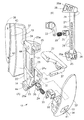
次に、本願発明の実施形態を図面に基づいて説明する。まず、図1〜4に基づいて椅子の概要を説明する。本実施形態の椅子は事務用に多用されている回転椅子であり、座1、背もたれ2、キャスタ付きの脚装置3を主要要素として備えている。脚装置3を構成する脚支柱4(図1(A)参照)の上端にベース体5(図2(B))を設け、ベース体5に背枠6が後傾動自在に連結されている。
(1). Outline Next, an embodiment of the present invention will be described with reference to the drawings. First, the outline of the chair will be described with reference to FIGS. The chair of the present embodiment is a swivel chair that is often used for office work, and includes a
ベース体5と背枠6とに中間部材7が連結されており、中間部材7に座1が取り付けられている。中間部材7は、背もたれ2が後傾すると上昇しつつ後退する。従って、背もたれ2の後傾動に対して、着座者の体重の一部が抵抗として作用する(ロッキング抵抗が体重感応する。)。
An
背もたれ2は、既述の背枠6と、その前面に取り付けたフロントフレーム8とを有している。背枠6及びフロントフレーム8は樹脂製であり、両者とも、上下長手の左右サイドメンバー6a,8aと、その上端に繋がったアッパメンバー6b,8bと、サイドメンバー6a,8aの下端に繋がったロアメンバー6c,8cとを有している。
The
また、背枠6は前向きに開口した溝形であり、フロントフレーム8は後ろ向きに開口した溝形になっている。従って、フロントフレーム8は、背枠6の溝を塞ぐような状態で、フロントフレーム8に取り付けられている。背枠6のロアメンバー6cには、左右一対の前向きアーム6dが形成されており、前向きアーム6dの前端部がベース体5に連結されている。なお、背枠6と前向きアーム部6dとを一体化せずに、ベース5に後傾動自在に連結された傾動部材に背枠6を取り付けてもよい。
Further, the
フロントフレーム8には、サポート体の一例としてのメッシュ材9が取り付けられている。メッシュ材9の取り付け手段としては、メッシュ材9の外周にテープ状の縁部材を固定して、左右側部と下部とにおいては、縁部材を、フロントフレーム8の背面(後面)に形成した突起に係合させており、フロントフレーム8の上部においては、アッパメンバー8bに形成した溝に嵌め込んでいる。
A
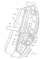
背枠6へのフロントフレーム8の取り付け手段としては、図3に示すように、まず、フロントフレーム8のサイドメンバー8aに下向き係合爪10を上下に複数個形成して、各下向き係合爪10を、背枠6のサイドメンバー6aに形成した上向き係合爪11に嵌め込んでいる。また、フロントフレーム8のサイドメンバー8aに板状の位置決めリブ12を複数の高さ位置に形成する一方、背枠6のサイドメンバー6aには、位置決めリブ12が左右ずれ不能に嵌まる嵌合部13を形成している。
As a means for attaching the
また、フロントフレーム8のアッパメンバー8bの左右両端部に下向き鉤状の上係合爪14を形成している一方、背枠6のアッパメンバー6bに、上係合爪14が上から嵌まる受け部15を形成しており、上係合爪14は、背枠6のアッパメンバー6bで簡単には上下にずれない状態に保持されている。
Further, while the left and right ends of the
図4に明瞭に示すように、背枠6のサイドメンバー6aの下寄り部位は側面視でく字形に曲がっている一方、フロントフレーム8のサイドメンバー8aも、着座者の腰のあたりが最も前になるように側面視で略く字状に曲がっている。この場合、フロントフレーム8におけるサイドメンバー8aの頂点が、背枠6におけるサイドメンバー6aの頂点よりも下方に位置しており、かつ、フロントフレーム8のうち背枠6のサイドメンバー6aの頂点よりも下方の部位はオーバーハング部になっている。従って、フロントフレーム8の下端は、背枠6に固定されていない自由端になっている。
As is clearly shown in FIG. 4, the lower portion of the
そして、フロントフレーム8におけるサイドメンバー8aの自由端部に、メッシュ材9を後ろから支えるランバーサポート装置16を取り付けている。次に、ランバーサポート装置16を説明する。
A
(2).ランバーサポート装置
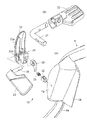
図6から容易に理解できるように、ランバーサポート装置16は、前向きに開口した箱状の本体ケース(カバー)19と、その内部に嵌め入れた溝形の昇降スライダ20と、昇降スライダ20で挟まれた状態で本体ケース19の内部に配置した昇降ガイド部材21と、本体ケース19の手前に配置したランバーパッド22と、昇降スライダ20及びランバーパッド22に連結されたレバー23とを有している。昇降ガイド部材21は、本体ケース19に嵌め込んだだけでもよいし、ビスで本体ケース19に固定してもよい。
(2). As will be readily appreciated from the
本体ケース19の底部は後ろ向きに狭まっており、このため、昇降スライダ20は、コ字を変形させたような平面視形状になっている。レバー23は、ランバーパッド22の後面から後ろ向きに延びている。また、ランバーパッド22は上下長手であり、全体として丸みを帯びている。更に、図5(A)や図7(A)に示すように、ランバーパッド22には、本体ケース19の外面に重なるガイドリブ板22aを設けている。
The bottom of the
本体ケース19は上下方向に長い形状であり、昇降ガイド部材21も、本体ケース19の内部の上下端まで長く延びている。そして、昇降ガイド部材21の上下両端に後ろ向きの足部24を設けることにより、上下足部24の間において昇降ガイド部材21と本体ケース19との間に隙間を形成し、これにより、昇降スライダ20の上下スライドを許容している。昇降ガイド部材21の上下両端部には、足部24を有するヘッド部25が形成されており、ヘッド部25が、本体ケース19に左右ずれ不能及び上下ずれ不能に嵌まっている。
The
図8からよく理解できるように、ランバーパッド22の後面には、角形のホルダー部26を形成して、ホルダー部26を昇降スライダ20の左右側板の間に嵌め入れている一方、レバー23には横向きの支軸27を固定して、支軸27でホルダー部26と昇降スライダ20とを連結している。従って、ランバーパッド22とレバー23と昇降ガイド部材21は一緒に上下動(昇降)する。
As can be well understood from FIG. 8, a
図8(A)に示すように、本体ケース19のうちフロントフレーム8と反対側の内側板に、支軸27が密接して上下動するガイド溝19bを形成している。支軸27がガイド溝19bに当接して上下動することにより、ランバーパッド22を安定的に保持できる。他方、図8(A)に明示するように、ランバーパッド22には、本体ケース19の内側に配置した側板22bを形成しており、側板22bには、支軸27との衝突を回避するための切欠き22cを形成している。
As shown in FIG. 8A, a
ランバーパッド22は、複数の高さ位置に段階的に保持される。このため、昇降ガイド部材21に複数段の係合溝(或いは係合突起)28を形成して、この係合溝28に、ばね29で付勢されたストッパー30を当接させている。従って、係合溝28とストッパー30とが、請求項に記載した係合手段になる。係合溝28は、上下長手の長溝31の底部に形成している。このため、ストッパー30は長溝31によって、左右ずれ不能に保持されている。ストッパー30の後端は、上下動して係合溝28に容易に嵌脱するように、側面視山形に形成されている。
The
図10に示すように、ストッパー30は、ランバーパッド22のホルダー部26に前後動自在に嵌まっており、かつ、ばね29で後ろ方向に付勢されている。従って、ばね29は、ホルダー部26の底面とストッパー30との間に脱落不能に配置されている。
As shown in FIG. 10, the
ストッパー30に上向きに開口した角穴32が空いている一方、ランバーパッド22のホルダー部26には、レバー23の支軸27に固定されたアーム体33が嵌め込まれており、アーム体33の先端部をストッパー30の角穴32に嵌め入れている。アーム体33は、おおまかにはL形に形成されており、ビス34で支軸27に固定されている。図6(A)及び図7(B)では、ビス34は矢印で表示している。ランバーパッド22には、ビス34を挿入するための逃がし穴35(図6(A)参照)が開口している。
While the
レバー23を図10の矢印36の方向に回動させると、ストッパー30がばね29に抗して後退する。従って、昇降スライダ20とランバーパッド22とレバー23とを昇降させることができる。レバー23から手を離すと、ストッパー30がばね29で押されて、昇降スライダ20及びランバーパッド22の高さが保持される。
When the
図10のとおり、昇降ガイド部材21の係合溝28は、上面は緩く傾斜した傾斜面28aになって、下面は水平になっている。このため、レバー23に指を当てて上に押すと、ストッパー30は昇降ガイド部材21に押され勝手になるが、傾斜面28aのガイド作用が勝って、昇降スライダ20とランバーパッド22を上昇させることができる。すなわち、ストッパー30がばね29に抗して手前に逃げ移動することにより、ランバーパッド22の上昇動が許容される。
As shown in FIG. 10, the upper surface of the engaging
レバー23を下向きに押すと、アーム33が回動してストッパー30は係合溝28から逃げる。このため、昇降スライダ20やランバーパッド22を下降させることができる。さて、着座者が背もたれ2にもたれ掛かると、ランバーパッド22に下向きの分力がかかるため、ストッパー30と係合溝28との係合が浅いと、ストッパー30やランバーパッド22が下降動してしまうことがある。
When the
しかし、本実施形態では、ストッパー33の下降動に対しては係合溝28が抵抗としてしっかり機能するため、ランバーパッド22が、着座者の体圧によって意図せずに下降してしまうことを防止できる。なお、ランバーパッド22の高さ調節の段数は任意に設定できる。また、ランバーパッド22は、無段階的に高さ調節できるようにすることも可能である。
However, in the present embodiment, since the engaging
図11に明示するように、本体ケース19の外側面19aは、ランバーパッド22におけるサイドメンバー8aの内側面に重なっており、かつ、本体ケース19には、ランバーパッド22におけるサイドメンバー8aの後端に重なるリブ37を設けている。このため、本体ケース19はフロントフレーム8のサイドメンバー8aにきっちりと位置決めされる。そして、本体ケース19は、図示してないビスにより、フロントフレーム8のサイドメンバー8aに固定されている。
As is clearly shown in FIG. 11, the outer surface 19a of the
また、本体ケース19には後ろ向きに延びる翼片38を設けており、翼片38を背枠6におけるサイドメンバー6aの内側面に密接させている。翼片38は、後ろ向きのある程度の移動を許容した状態で、背枠6におけるサイドメンバー6aに重なっている。従って、フロントフレーム8のオーバーハング部(下部)が後ろ向きに曲がり変形することが許容されている。また、人が何らかの理由で本体ケース19に手を触れたままでロッキングしても、本体ケース19と背枠6との間に指を挟むようなことはない。
Further, the
図8(B)、図6(A)に示すように、昇降スライダ20の内側板20aに、下向き鉤部39を形成しており、図8(B)から理解できるように、昇降スライダ20の内側板20aは、ランバーパッド22のホルダー部26と内側板22aとで挟んでおり、ホルダー部26と内側板22aとに掛け渡した状態で、昇降スライダ20の下向き鉤部39に嵌合する係合板40を形成している。
As shown in FIGS. 8 (B) and 6 (A), a
従って、ランバーパッド22と昇降スライダ20とが下部においてしっかりと嵌まり合っており、かつ、係合板40と下向き鉤部との嵌合(係合)により、前後離反不能に保持されている。なお、ランバーパッド22は樹脂の射出成形品であり、前後から重なる形状の金型を使用して成形されるが、ランバーパッド22には、係合板40を形成するための抜き違い穴41が開口している。
Therefore, the
図9(B)に示すように、本体ケース19と昇降ガイド部材21は、ビス42でフロントフレーム8のサイドメンバー8aに締結(固定)されている。すなわち、本体ケース19と昇降ガイド部材21とフロントフレーム8とが、ビス42で共締めされている。従って、フロントフレーム8のサイドメンバー8aと本体ケース19の一側板とには、ビス挿通穴43が空いており、昇降ガイド部材21の上下ヘッド部25にも、ビス42の挿通穴44を形成している。そして、図6や図9に示すように、ヘッド部25には、ビス42がねじ込まれるナット(図示せず)を回転不能に保持するポケット部25aを設けている。この場合、図6の例では、ポケット部25aは手前に開口して、図9の例では後ろ向きに開口している。従って、ヘッド部25は、図6と図9とで少し相違している。
As shown in FIG. 9B, the
フロントフレーム8のビス挿通穴43は、フロントフレーム8における内壁8′の内面に形成した台座部46に空けており、また、台座部46の上下両側又は片側には、表面から折り返されたメッシュ材9の縁部、又は、メッシュ材9の縁に固定した縁部材が重なるリブ47を形成している。従って、メッシュ材9の折り返し部又は縁部材の後ろは空間になっており、ビス42の頭はメッシュ材9又はその縁部材で隠れている。このため、美観の悪化は生じない。
The
(3).まとめ
本実施形態では、ランバーサポート装置16は、フロントフレーム8における左右サイドメンバー8aの内側面の箇所に配置しているため、ランバーサポート装置16はあまり目立たない。このため、体裁がよい。また、ランバーパッド22の身体が当たることは全く又は殆どない。このため、突っ張り感を無くした状態でランバーサポート機能を発揮できる。
(3). Summary In the present embodiment, since the
図11及び図1(C)から理解できるように、本実施形態では、ランバーパッド22はホルダー部26から上側に大きく張り出している。このため、ホルダー部26が昇降ガイド部材21の上端部に位置しても、ランバーパッド22の上端を本体ケース19の上方にはみ出させることができる。このため、本体ケース19をフロントフレーム8のオーバーハング部に配置していても、ランバーパッド22によるランバーサポート位置調節機能を的確に発揮できる(フロントフレーム8におけるサイドメンバー8aの頂点部より上の位置に、ランバーサポート部を持ってくることができる。)。
As can be understood from FIGS. 11 and 1 (C), in the present embodiment, the
本実施形態では、左右のランバーサポート装置を分けて配置したが、左右横長のステーをフロントフレームの左右サイドメンバーに固定して、このステーにランバーパッドを取り付けてもよい。ランバーパッドは高さ調節自在でなくてもよい。ランバーパッドを左右に分離して設けた場合、左右のランバーパッドをステーで繋いで、ステーに操作部を設けることにより、左右のランバーパッドを同時に昇降できるようにしてもよい。 In the present embodiment, the left and right lumbar support devices are arranged separately, but the left and right horizontally long stays may be fixed to the left and right side members of the front frame, and the lumbar pads may be attached to the stays. The lumbar pad does not have to be height adjustable. When the lumbar pads are provided separately on the left and right, the left and right lumbar pads may be raised and lowered at the same time by connecting the left and right lumbar pads with stays and providing an operation unit on the stay.
例えば図1(C)に示すように、左右の本体ケース19は、上に行くに従って間隔が広がるように正面視で逆ハ字状の姿勢に配置されている。従って、ランバーパッド22は、鉛直線に対して傾斜した方向に上下動する。これは、フロントフレーム8におけるサイドメンバー8aの姿勢に起因したものであるが、結果としては、ランバーパッド22が高くなるほどメッシュ材9に対に強いテンションを掛ける作用が生じている。また、ランバーパッド22が高くなるほど、ランバーパッド22は身体に当たりにくくなる。
For example, as shown in FIG. 1C, the left and right
本実施形態では、フロントフレーム8と昇降ガイド部材21と本体ケース19とは、上下2本のビス42で共締めされている。このため、少ない本数のビス42でランバーサポート装置16をしっかりと固定できる。ランバーサポート装置16をオプション品として、ランバーサポート装置16を備えた背もたれ2と備えていない背もたれ2とを用意することが可能であるが、フロントフレーム8のビス挿通穴43はバックビューにおいて人目にふれにくいため、ランバーサポート装置16を取り付けていない仕様でも美観の問題は生じない。従って、ランバーサポート装置16を備えているタイプと備えていないタイプとで背もたれ2を共通化して、コストを抑制できる。
In the present embodiment, the
図9(A)から明瞭に理解できるように、レバー23は、手前の幅が狭くて後ろが広くなった形状になっているため、組み付け前において、例えばランバーパッド22だけを持ち上げたような場合に、ランバーサポート装置16が分離してしまうことを防止できる。
As can be clearly understood from FIG. 9 (A), the
つまり、本体ケース19を除いたランバーパッド22等の各部材は分離しない状態にユニット化されているが、本体ケース19はユニットに対して嵌まっているだけであるため、特段の手当てをしないと、ランバーサポート装置16を手で持ち上げると本体ケース19が抜けてしまうというように、扱い方次第で、ユニットと本体ケース19とが簡単に分離してしまうことになるが、本実施形態では、レバー23を取り付けると、一部の部材を掴んで持ち上げても、レバー23の広幅部が本体ケース19に当たることにより、ランバーパッド22等のユニットと本体ケース19とが分離する(一方が脱落する)ことを防止して、ランバーサポート装置16が一体化した状態を保持できるのである。従って、組み付け前の段階でランバーサポート装置16がばらけてしまうことを、バンド等の部材を要することなく防止できるのである。
That is, each member such as the
また、レバー23の後半部は、フロントフレーム8の側に向けて広がる形態になっているため、できるだけ目立たない状態にしつつ、指をしっかりと当てる面積を確保することができる。
Further, since the latter half of the
フロントフレームのサイドメンバーは、実施形態のように下部をオーバーハング部に形成する必要はないのであり、全体を背枠の前面に重ねてもよい。また、フロントフレームは、背枠にビス等のファスナで固定してもよい。 The side members of the front frame do not need to have the lower portion formed on the overhang portion as in the embodiment, and the entire side member may be overlapped on the front surface of the back frame. Further, the front frame may be fixed to the back frame with fasteners such as screws.
本願発明は、実際に椅子に具体化できる。従って、産業上利用できる。 The invention of the present application can be actually embodied in a chair. Therefore, it can be used industrially.
2 背もたれ
6 背枠
6a サイドメンバー
8 フロントフレーム
8a サイドメンバー
9 サポート体の一例としてのメッシュ材
16 ランバーサポート装置
19 本体ケース
20 昇降スライダ
21 昇降ガイド部材
22 ランバーパッド
23 レバー
25 ヘッド部
26 ホルダー部
27 支軸
28 係合溝
29 ばね
30 ストッパー
33 アーム
37 リブ
38 翼片
42 ビス
2
42 screws
Claims (4)
かつ、前記フロントフレームの左右側部の内側部に、前記サポート体を後ろから支えるランバーサポート装置が取り付けられている構成であって、
前記ランバーサポート装置は、前記フロントフレームに固定された昇降ガイド部材と、前記昇降ガイド部材に昇降自在に取り付けたランバーパッドと、前記ランバーパッドを昇降操作する操作具とを備えており、前記昇降ガイド部材とランバーパッドとに、前記ランバーパッドを設定した高さに保持する係合手段を設けている、
椅子の背もたれ。 The CFCs bets frame attached to overlap the front of the back frame which is open in the longitudinal, deformable support body for supporting the body pressure of the occupant is provided,
And, wherein the inner portion of the left and right sides of the front frame, a structure in which the lumbar support device is mounted for supporting the front Symbol support member from behind,
The lumbar support device includes an elevating guide member fixed to the front frame, a lumbar pad movably attached to the elevating guide member, and an operating tool for elevating and lowering the lumbar pad. The member and the lumbar pad are provided with engaging means for holding the lumbar pad at a set height.
The back of the chair.
請求項1に記載した椅子の背もたれ。 The elevating guide member includes a main body case incorporating the elevating guide member.
The backrest of the chair according to claim 1.
前記フロントフレームと本体ケースと昇降ガイド部材とがビスで共締めされている、
請求項2に記載した椅子の背もたれ。 The main body case overlaps the front frame and
The front frame, the main body case, and the elevating guide member are fastened together with screws.
The backrest of the chair according to claim 2.
請求項3に記載した椅子の背もたれ。 The screw is inserted into the front frame from the outside and screwed into the elevating guide member, and the head of the screw is hidden by the support body overlapping the front frame from the front.
The backrest of the chair according to claim 3.
Priority Applications (1)
| Application Number | Priority Date | Filing Date | Title |
|---|---|---|---|
| JP2016216756A JP6876409B2 (en) | 2016-11-04 | 2016-11-04 | Chair back |
Applications Claiming Priority (1)
| Application Number | Priority Date | Filing Date | Title |
|---|---|---|---|
| JP2016216756A JP6876409B2 (en) | 2016-11-04 | 2016-11-04 | Chair back |
Publications (2)
| Publication Number | Publication Date |
|---|---|
| JP2018068980A JP2018068980A (en) | 2018-05-10 |
| JP6876409B2 true JP6876409B2 (en) | 2021-05-26 |
Family
ID=62111837
Family Applications (1)
| Application Number | Title | Priority Date | Filing Date |
|---|---|---|---|
| JP2016216756A Active JP6876409B2 (en) | 2016-11-04 | 2016-11-04 | Chair back |
Country Status (1)
| Country | Link |
|---|---|
| JP (1) | JP6876409B2 (en) |
Families Citing this family (3)
| Publication number | Priority date | Publication date | Assignee | Title |
|---|---|---|---|---|
| JP7245000B2 (en) * | 2018-05-17 | 2023-03-23 | 株式会社イトーキ | chair lumbar support |
| JP7307537B2 (en) * | 2018-10-09 | 2023-07-12 | 株式会社イトーキ | Chair |
| JP7280737B2 (en) * | 2019-03-29 | 2023-05-24 | 株式会社オカムラ | Load bearing mechanisms, backrests and chairs |
Family Cites Families (4)
| Publication number | Priority date | Publication date | Assignee | Title |
|---|---|---|---|---|
| JP3144491U (en) * | 2008-03-19 | 2008-09-04 | 呉 耀全 | Seat back structure |
| JP4897912B2 (en) * | 2009-11-02 | 2012-03-14 | 日本特殊陶業株式会社 | Gas sensor |
| JP2012071026A (en) * | 2010-09-29 | 2012-04-12 | Itoki Corp | Chair with backrest |
| KR101379931B1 (en) * | 2013-01-02 | 2014-04-01 | 부호체어원(주) | Mesh-type chair with a variable support section |
-
2016
- 2016-11-04 JP JP2016216756A patent/JP6876409B2/en active Active
Also Published As
| Publication number | Publication date |
|---|---|
| JP2018068980A (en) | 2018-05-10 |
Similar Documents
| Publication | Publication Date | Title |
|---|---|---|
| US9510682B2 (en) | Nestable chair | |
| JP5646725B2 (en) | Rocking chair | |
| JP6876409B2 (en) | Chair back | |
| JP4575233B2 (en) | Chair | |
| JP2008302082A (en) | Rocking chair | |
| JP5451027B2 (en) | Rocking chair | |
| JP6009627B2 (en) | Chair and its outer shell | |
| JP5508620B2 (en) | Chair | |
| JP5860513B2 (en) | Chair | |
| JP2003079476A (en) | Chair | |
| JP5601818B2 (en) | Rocking chair | |
| JP2015171652A5 (en) | ||
| JP2020058769A (en) | Chair | |
| JP2002136388A (en) | Backrest structure for chair | |
| JP7217110B2 (en) | Chair | |
| JP2017113465A (en) | Backrest of chair | |
| JP6080902B2 (en) | Chair with backrest | |
| JP5576110B2 (en) | Hanger device or headrest device for chair and chair provided with the same | |
| JP2014042855A (en) | Backrest or seat of chair | |
| JP6670069B2 (en) | Chair | |
| JP6909336B2 (en) | Chair back | |
| JP7299004B2 (en) | Chair | |
| JP6643047B2 (en) | Chair backrest | |
| JP6960824B2 (en) | Chair | |
| JP2015157224A5 (en) |
Legal Events
| Date | Code | Title | Description |
|---|---|---|---|
| A521 | Written amendment |
Free format text: JAPANESE INTERMEDIATE CODE: A523 Effective date: 20170120 |
|
| A621 | Written request for application examination |
Free format text: JAPANESE INTERMEDIATE CODE: A621 Effective date: 20191024 |
|
| A977 | Report on retrieval |
Free format text: JAPANESE INTERMEDIATE CODE: A971007 Effective date: 20201118 |
|
| A131 | Notification of reasons for refusal |
Free format text: JAPANESE INTERMEDIATE CODE: A131 Effective date: 20201202 |
|
| A521 | Written amendment |
Free format text: JAPANESE INTERMEDIATE CODE: A523 Effective date: 20210201 |
|
| TRDD | Decision of grant or rejection written | ||
| A01 | Written decision to grant a patent or to grant a registration (utility model) |
Free format text: JAPANESE INTERMEDIATE CODE: A01 Effective date: 20210331 |
|
| A61 | First payment of annual fees (during grant procedure) |
Free format text: JAPANESE INTERMEDIATE CODE: A61 Effective date: 20210426 |
|
| R150 | Certificate of patent or registration of utility model |
Ref document number: 6876409 Country of ref document: JP Free format text: JAPANESE INTERMEDIATE CODE: R150 |