JP6008637B2 - Vehicle headlamp - Google Patents
Vehicle headlamp Download PDFInfo
- Publication number
- JP6008637B2 JP6008637B2 JP2012164732A JP2012164732A JP6008637B2 JP 6008637 B2 JP6008637 B2 JP 6008637B2 JP 2012164732 A JP2012164732 A JP 2012164732A JP 2012164732 A JP2012164732 A JP 2012164732A JP 6008637 B2 JP6008637 B2 JP 6008637B2
- Authority
- JP
- Japan
- Prior art keywords
- lamp unit
- light distribution
- distribution pattern
- lamp
- vehicle
- Prior art date
- Legal status (The legal status is an assumption and is not a legal conclusion. Google has not performed a legal analysis and makes no representation as to the accuracy of the status listed.)
- Expired - Fee Related
Links
Images


Classifications
-
- F—MECHANICAL ENGINEERING; LIGHTING; HEATING; WEAPONS; BLASTING
- F21—LIGHTING
- F21S—NON-PORTABLE LIGHTING DEVICES; SYSTEMS THEREOF; VEHICLE LIGHTING DEVICES SPECIALLY ADAPTED FOR VEHICLE EXTERIORS
- F21S41/00—Illuminating devices specially adapted for vehicle exteriors, e.g. headlamps
- F21S41/10—Illuminating devices specially adapted for vehicle exteriors, e.g. headlamps characterised by the light source
- F21S41/14—Illuminating devices specially adapted for vehicle exteriors, e.g. headlamps characterised by the light source characterised by the type of light source
- F21S41/141—Light emitting diodes [LED]
- F21S41/143—Light emitting diodes [LED] the main emission direction of the LED being parallel to the optical axis of the illuminating device
-
- B—PERFORMING OPERATIONS; TRANSPORTING
- B60—VEHICLES IN GENERAL
- B60Q—ARRANGEMENT OF SIGNALLING OR LIGHTING DEVICES, THE MOUNTING OR SUPPORTING THEREOF OR CIRCUITS THEREFOR, FOR VEHICLES IN GENERAL
- B60Q1/00—Arrangement of optical signalling or lighting devices, the mounting or supporting thereof or circuits therefor
- B60Q1/02—Arrangement of optical signalling or lighting devices, the mounting or supporting thereof or circuits therefor the devices being primarily intended to illuminate the way ahead or to illuminate other areas of way or environments
- B60Q1/04—Arrangement of optical signalling or lighting devices, the mounting or supporting thereof or circuits therefor the devices being primarily intended to illuminate the way ahead or to illuminate other areas of way or environments the devices being headlights
- B60Q1/06—Arrangement of optical signalling or lighting devices, the mounting or supporting thereof or circuits therefor the devices being primarily intended to illuminate the way ahead or to illuminate other areas of way or environments the devices being headlights adjustable, e.g. remotely-controlled from inside vehicle
-
- B—PERFORMING OPERATIONS; TRANSPORTING
- B60—VEHICLES IN GENERAL
- B60Q—ARRANGEMENT OF SIGNALLING OR LIGHTING DEVICES, THE MOUNTING OR SUPPORTING THEREOF OR CIRCUITS THEREFOR, FOR VEHICLES IN GENERAL
- B60Q1/00—Arrangement of optical signalling or lighting devices, the mounting or supporting thereof or circuits therefor
- B60Q1/02—Arrangement of optical signalling or lighting devices, the mounting or supporting thereof or circuits therefor the devices being primarily intended to illuminate the way ahead or to illuminate other areas of way or environments
- B60Q1/04—Arrangement of optical signalling or lighting devices, the mounting or supporting thereof or circuits therefor the devices being primarily intended to illuminate the way ahead or to illuminate other areas of way or environments the devices being headlights
- B60Q1/14—Arrangement of optical signalling or lighting devices, the mounting or supporting thereof or circuits therefor the devices being primarily intended to illuminate the way ahead or to illuminate other areas of way or environments the devices being headlights having dimming means
- B60Q1/1415—Dimming circuits
- B60Q1/1423—Automatic dimming circuits, i.e. switching between high beam and low beam due to change of ambient light or light level in road traffic
- B60Q1/143—Automatic dimming circuits, i.e. switching between high beam and low beam due to change of ambient light or light level in road traffic combined with another condition, e.g. using vehicle recognition from camera images or activation of wipers
-
- F—MECHANICAL ENGINEERING; LIGHTING; HEATING; WEAPONS; BLASTING
- F21—LIGHTING
- F21S—NON-PORTABLE LIGHTING DEVICES; SYSTEMS THEREOF; VEHICLE LIGHTING DEVICES SPECIALLY ADAPTED FOR VEHICLE EXTERIORS
- F21S41/00—Illuminating devices specially adapted for vehicle exteriors, e.g. headlamps
- F21S41/10—Illuminating devices specially adapted for vehicle exteriors, e.g. headlamps characterised by the light source
- F21S41/14—Illuminating devices specially adapted for vehicle exteriors, e.g. headlamps characterised by the light source characterised by the type of light source
- F21S41/141—Light emitting diodes [LED]
- F21S41/151—Light emitting diodes [LED] arranged in one or more lines
- F21S41/153—Light emitting diodes [LED] arranged in one or more lines arranged in a matrix
-
- F—MECHANICAL ENGINEERING; LIGHTING; HEATING; WEAPONS; BLASTING
- F21—LIGHTING
- F21S—NON-PORTABLE LIGHTING DEVICES; SYSTEMS THEREOF; VEHICLE LIGHTING DEVICES SPECIALLY ADAPTED FOR VEHICLE EXTERIORS
- F21S41/00—Illuminating devices specially adapted for vehicle exteriors, e.g. headlamps
- F21S41/60—Illuminating devices specially adapted for vehicle exteriors, e.g. headlamps characterised by a variable light distribution
- F21S41/65—Illuminating devices specially adapted for vehicle exteriors, e.g. headlamps characterised by a variable light distribution by acting on light sources
- F21S41/663—Illuminating devices specially adapted for vehicle exteriors, e.g. headlamps characterised by a variable light distribution by acting on light sources by switching light sources
-
- F—MECHANICAL ENGINEERING; LIGHTING; HEATING; WEAPONS; BLASTING
- F21—LIGHTING
- F21S—NON-PORTABLE LIGHTING DEVICES; SYSTEMS THEREOF; VEHICLE LIGHTING DEVICES SPECIALLY ADAPTED FOR VEHICLE EXTERIORS
- F21S41/00—Illuminating devices specially adapted for vehicle exteriors, e.g. headlamps
- F21S41/60—Illuminating devices specially adapted for vehicle exteriors, e.g. headlamps characterised by a variable light distribution
- F21S41/68—Illuminating devices specially adapted for vehicle exteriors, e.g. headlamps characterised by a variable light distribution by acting on screens
- F21S41/683—Illuminating devices specially adapted for vehicle exteriors, e.g. headlamps characterised by a variable light distribution by acting on screens by moving screens
- F21S41/698—Shaft-shaped screens rotating along its longitudinal axis
-
- B—PERFORMING OPERATIONS; TRANSPORTING
- B60—VEHICLES IN GENERAL
- B60Q—ARRANGEMENT OF SIGNALLING OR LIGHTING DEVICES, THE MOUNTING OR SUPPORTING THEREOF OR CIRCUITS THEREFOR, FOR VEHICLES IN GENERAL
- B60Q1/00—Arrangement of optical signalling or lighting devices, the mounting or supporting thereof or circuits therefor
- B60Q1/02—Arrangement of optical signalling or lighting devices, the mounting or supporting thereof or circuits therefor the devices being primarily intended to illuminate the way ahead or to illuminate other areas of way or environments
- B60Q1/04—Arrangement of optical signalling or lighting devices, the mounting or supporting thereof or circuits therefor the devices being primarily intended to illuminate the way ahead or to illuminate other areas of way or environments the devices being headlights
- B60Q1/14—Arrangement of optical signalling or lighting devices, the mounting or supporting thereof or circuits therefor the devices being primarily intended to illuminate the way ahead or to illuminate other areas of way or environments the devices being headlights having dimming means
- B60Q1/1415—Dimming circuits
- B60Q1/1423—Automatic dimming circuits, i.e. switching between high beam and low beam due to change of ambient light or light level in road traffic
-
- B—PERFORMING OPERATIONS; TRANSPORTING
- B60—VEHICLES IN GENERAL
- B60Q—ARRANGEMENT OF SIGNALLING OR LIGHTING DEVICES, THE MOUNTING OR SUPPORTING THEREOF OR CIRCUITS THEREFOR, FOR VEHICLES IN GENERAL
- B60Q2300/00—Indexing codes for automatically adjustable headlamps or automatically dimmable headlamps
- B60Q2300/05—Special features for controlling or switching of the light beam
- B60Q2300/056—Special anti-blinding beams, e.g. a standard beam is chopped or moved in order not to blind
-
- B—PERFORMING OPERATIONS; TRANSPORTING
- B60—VEHICLES IN GENERAL
- B60Q—ARRANGEMENT OF SIGNALLING OR LIGHTING DEVICES, THE MOUNTING OR SUPPORTING THEREOF OR CIRCUITS THEREFOR, FOR VEHICLES IN GENERAL
- B60Q2300/00—Indexing codes for automatically adjustable headlamps or automatically dimmable headlamps
- B60Q2300/30—Indexing codes relating to the vehicle environment
- B60Q2300/32—Road surface or travel path
- B60Q2300/322—Road curvature
-
- B—PERFORMING OPERATIONS; TRANSPORTING
- B60—VEHICLES IN GENERAL
- B60Q—ARRANGEMENT OF SIGNALLING OR LIGHTING DEVICES, THE MOUNTING OR SUPPORTING THEREOF OR CIRCUITS THEREFOR, FOR VEHICLES IN GENERAL
- B60Q2300/00—Indexing codes for automatically adjustable headlamps or automatically dimmable headlamps
- B60Q2300/40—Indexing codes relating to other road users or special conditions
- B60Q2300/41—Indexing codes relating to other road users or special conditions preceding vehicle
-
- B—PERFORMING OPERATIONS; TRANSPORTING
- B60—VEHICLES IN GENERAL
- B60Q—ARRANGEMENT OF SIGNALLING OR LIGHTING DEVICES, THE MOUNTING OR SUPPORTING THEREOF OR CIRCUITS THEREFOR, FOR VEHICLES IN GENERAL
- B60Q2300/00—Indexing codes for automatically adjustable headlamps or automatically dimmable headlamps
- B60Q2300/40—Indexing codes relating to other road users or special conditions
- B60Q2300/42—Indexing codes relating to other road users or special conditions oncoming vehicle
-
- B—PERFORMING OPERATIONS; TRANSPORTING
- B60—VEHICLES IN GENERAL
- B60Q—ARRANGEMENT OF SIGNALLING OR LIGHTING DEVICES, THE MOUNTING OR SUPPORTING THEREOF OR CIRCUITS THEREFOR, FOR VEHICLES IN GENERAL
- B60Q2300/00—Indexing codes for automatically adjustable headlamps or automatically dimmable headlamps
- B60Q2300/40—Indexing codes relating to other road users or special conditions
- B60Q2300/45—Special conditions, e.g. pedestrians, road signs or potential dangers
Landscapes
- Engineering & Computer Science (AREA)
- General Engineering & Computer Science (AREA)
- Physics & Mathematics (AREA)
- Microelectronics & Electronic Packaging (AREA)
- Optics & Photonics (AREA)
- Mechanical Engineering (AREA)
- Mathematical Physics (AREA)
- Lighting Device Outwards From Vehicle And Optical Signal (AREA)
- Non-Portable Lighting Devices Or Systems Thereof (AREA)
Description
本発明は、車両が走行する環境に応じて配光パターンを変更する車両用前照灯に関する。 The present invention relates to a vehicle headlamp that changes a light distribution pattern according to an environment in which the vehicle travels.
水平線よりも上側で左右方向に分割された複数の個別照射領域をそれぞれ照射可能に構成された、複数個の半導体発光素子からなる発光素子アレイを備える車両用前照灯が知られている。このような車両用前照灯では、前走車や歩行者の位置を検出し、その位置に対応する個別照射領域を照射しないように発光素子アレイを制御することで、前走車のドライバーや歩行者にグレアを与えないようにするADB(Adaptive Driving Beam)を実現することができる。また、水平線よりも上側の領域を左右方向のみならず上下方向にも複数段に分割した格子状の個別照射領域を照射可能とするように発光素子アレイを構成することで、上下方向のカットオフラインを有する配光パターンを形成するようにした車両用前照灯も知られている(例えば、特許文献1)。 2. Description of the Related Art A vehicular headlamp is known that includes a light emitting element array composed of a plurality of semiconductor light emitting elements, each configured to be able to irradiate a plurality of individual irradiation areas divided in the left-right direction above a horizontal line. Such vehicle headlamps detect the position of the front vehicle and pedestrians and control the light emitting element array so as not to irradiate the individual irradiation area corresponding to the position of the front vehicle or the pedestrian. ADB (Adaptive Driving Beam) that prevents glare from being given to pedestrians can be realized. In addition, the vertical cut-off line is configured by configuring the light-emitting element array so that it can irradiate a grid-like individual irradiation area in which the area above the horizontal line is divided not only in the horizontal direction but also in the vertical direction. There is also known a vehicular headlamp configured to form a light distribution pattern having the above (for example, Patent Document 1).
上記の特許文献1のように、格子状の個別照射領域を用いてADBを実現する場合、上下方向の配光幅を個別照射領域の高さ単位でしか変更することができない。そのため、配光パターンの水平カットオフラインと前走車との間に大きな隙間が生まれ、遠方視認性の確保の点で重要である水平カットオフライン近傍を十分に照射することができない場合があるなど、適切でない配光パターンとなってしまうことがある。 When the ADB is realized by using a grid-like individual irradiation area as in Patent Document 1, the vertical light distribution width can be changed only in the height unit of the individual irradiation area. Therefore, a large gap is created between the horizontal cut-off line of the light distribution pattern and the preceding vehicle, and it may not be possible to sufficiently illuminate the vicinity of the horizontal cut-off line, which is important in ensuring distant visibility. Incorrect light distribution patterns may result.
本発明は、上述の課題に鑑みてなされたものであり、その目的は、二つの灯具ユニットによる照射範囲を組み合わせて種々の配光パターンを形成するときに、水平カットオフライン近傍を十分に照射することができる車両用前照灯を提供することにある。 The present invention has been made in view of the above-described problems, and its purpose is to sufficiently irradiate the vicinity of the horizontal cut-off line when forming various light distribution patterns by combining the irradiation ranges of the two lamp units. An object of the present invention is to provide a vehicular headlamp that can be used.
本発明のある態様の車両用前照灯は、水平方向に照射範囲を変更可能である第1灯具ユニットと、上下方向に照射範囲を変更可能である第2灯具ユニットと、を備え、第2灯具ユニットの照射範囲の分解能が、第1灯具ユニットの照射範囲の分解能よりも大きいことを特徴とする。 A vehicle headlamp according to an aspect of the present invention includes a first lamp unit that can change an irradiation range in a horizontal direction, and a second lamp unit that can change an irradiation range in an up and down direction. The resolution of the irradiation range of the lamp unit is larger than the resolution of the irradiation range of the first lamp unit.
この態様によると、上下方向に照射範囲を変更可能な第2灯具ユニットによる照射範囲の分解能が第1灯具ユニットよりも大きいため、いずれの配光パターンにおいても水平カットオフライン近傍を適切に照射することができる。なお、本明細書において「分解能」とは、各灯具ユニットにおいて照射範囲を切り替えるときの、仮想鉛直スクリーン上での照射範囲の増減面積の細かさのことを言う。 According to this aspect, since the resolution of the irradiation range by the second lamp unit that can change the irradiation range in the vertical direction is larger than that of the first lamp unit, the vicinity of the horizontal cutoff line can be appropriately irradiated in any light distribution pattern. Can do. In the present specification, “resolution” refers to the fineness of the increase / decrease area of the irradiation range on the virtual vertical screen when switching the irradiation range in each lamp unit.
前記第1灯具ユニットは、ロービーム用配光パターンの水平カットオフラインから上方の領域を水平方向に分割した照射範囲をそれぞれ有する、個別点灯可能に構成された複数の発光素子からなり、前記第2灯具ユニットは、アクチュエータの駆動により水平カットオフラインの高さを変更可能に構成され、第1灯具ユニットの点消灯および第2灯具ユニットのアクチュエータの駆動を制御する制御部をさらに備えてもよい。 The first lamp unit includes a plurality of light-emitting elements each configured to be individually lit, each having an irradiation range obtained by dividing an area above the horizontal cut-off line of the low beam distribution pattern in the horizontal direction, and the second lamp unit. The unit may be configured to change the height of the horizontal cutoff line by driving the actuator, and may further include a control unit that controls turning on / off of the first lamp unit and driving of the actuator of the second lamp unit.
これによると、水平方向での照射範囲を細かく設定することができる発光素子アレイ方式の灯具ユニットと、アレイ方式に比べて水平カットオフラインの上下方向での自由度が高いメカ切替方式の灯具ユニットとを組み合わせることで、種々の車両走行環境に合わせて取り得る配光パターンのバリエーションを増やすことができる。 According to this, a light emitting element array type lamp unit capable of finely setting the irradiation range in the horizontal direction, and a mechanical switching type lamp unit having a higher degree of freedom in the vertical direction of the horizontal cut-off line compared to the array type, By combining these, it is possible to increase the variation of the light distribution pattern that can be taken according to various vehicle driving environments.
第1灯具ユニットは、車体前部の左右いずれか一方の側に配置され、第2灯具ユニットは、車体前部の他方の側に配置されるとともに、シェードを動かして、ロービーム用配光パターンの水平カットオフラインの上下方向位置が異なる複数の配光パターンを形成可能であってもよい。これによると、水平方向の分解能しか有さない第1灯具ユニットを用いる場合でも、第2灯具ユニットで水平カットオフラインの上下方向位置を制御することで、遠方視認性の確保の点で重要である水平カットオフライン近傍を照射することが可能になる。 The first lamp unit is arranged on either the left or right side of the front part of the vehicle body, and the second lamp unit is arranged on the other side of the front part of the vehicle body, and the shade is moved so that the low beam light distribution pattern It may be possible to form a plurality of light distribution patterns whose horizontal cut-off lines have different vertical positions. According to this, even when the first lamp unit having only the horizontal resolution is used, it is important in terms of ensuring far visibility by controlling the vertical position of the horizontal cutoff line with the second lamp unit. Irradiation near the horizontal cut-off line is possible.
第1および第2灯具ユニットが車体前部の左右の側にそれぞれ設置され、車体の右側に配置された第1灯具ユニットの複数の発光素子による照射範囲と、車体の左側に配置された第1灯具ユニットの複数の発光素子による照射範囲が、仮想スクリーン上で垂直線を挟み両側にそれぞれ位置するように構成され、第2灯具ユニットは、ロービーム用配光パターンとハイビーム用配光パターンを形成可能であってもよい。これによると、車体前部の左右両側にそれぞれ、左右方向に広がる発光素子アレイ方式の灯具ユニットを設けた構成と比較して、各発光素子アレイの分割数が少なくて済むので、コストを削減することができる。 The first and second lamp units are installed on the left and right sides of the front part of the vehicle body, respectively, the irradiation range by the plurality of light emitting elements of the first lamp unit arranged on the right side of the vehicle body, and the first arranged on the left side of the vehicle body The illumination range of the lamp unit is configured to be located on both sides of the vertical line on the virtual screen, and the second lamp unit can form a low beam distribution pattern and a high beam distribution pattern. It may be. According to this, since the number of divisions of each light emitting element array can be reduced as compared with the configuration in which the light emitting element array type lamp unit extending in the left and right directions is provided on both the left and right sides of the front part of the vehicle body, the cost can be reduced. be able to.
本発明によれば、上下方向に照射範囲を変更可能な第2灯具ユニットによる照射範囲の分解能が第1灯具ユニットよりも大きいため、いずれの配光パターンにおいても水平カットオフライン近傍を適切に照射することができる。 According to the present invention, since the resolution of the irradiation range by the second lamp unit that can change the irradiation range in the vertical direction is larger than that of the first lamp unit, the vicinity of the horizontal cutoff line is appropriately irradiated in any light distribution pattern. be able to.
実施の形態1.
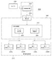
図1は、本発明の一実施形態に係る車両用前照灯10の概略正面図である。車両用前照灯10は、車体の前部に配置される左側灯具10Lと右側灯具10Rとを有する。左側灯具10Lは、LEDアレイ方式の灯具ユニット(以下「第1灯具ユニット」とも呼ぶ)20と、ハイ/ロー切替灯具ユニット60Lとを有する。右側灯具10Rは、水平方向のカットオフラインを機械的に変更可能に構成されたメカ切替方式の灯具ユニット(以下「第2灯具ユニット」とも呼ぶ)30と、ハイ/ロー切替灯具ユニット60Rとを有する。このように、本実施形態では、左側灯具10Lと右側灯具10Rとでそれぞれ異なる種類の灯具ユニットが設けられる。
Embodiment 1 FIG.
FIG. 1 is a schematic front view of a
図2は、LEDアレイ方式の第1灯具ユニット20の構成を説明する図である。図2は、第1灯具ユニット20を、光軸を含む水平面で切断して上方から見た断面図を示している。
FIG. 2 is a view for explaining the configuration of the LED array type
第1灯具ユニット20は、ホルダ24、投影レンズ22、および発光素子ユニット29を有する。
The
投影レンズ22は、前方側表面が凸面で後方側表面が平面の平凸非球面レンズからなり、その後側焦点面上に形成される光源像を、反転像として灯具前方の仮想鉛直スクリーン上に投影する。投影レンズ22は筒状に形成されたホルダ24の一方の開口部に取り付けられる。
The projection lens 22 is a plano-convex aspheric lens having a convex front surface and a flat rear surface, and projects a light source image formed on the rear focal plane onto a virtual vertical screen in front of the lamp as a reverse image. To do. The projection lens 22 is attached to one opening of a
発光素子ユニット29は、基板25、複数の半導体発光素子(例えばLED)からなる発光素子アレイ28、およびヒートシンク26を有する。発光素子アレイ28を構成する各発光素子は同一の高さを有する長方形に形成され、基板25の表面に帯状となるよう一直線状に配置される。実施の形態1では、各発光素子は同一の幅を有しており、個別点灯可能に構成される。発光素子ユニット29は、ホルダ24の他方の開口部に取り付けられる。
The light
発光素子はそれぞれ、発光チップ(図示せず)と薄膜を有する。発光チップは、例えば1mm角程度の正方形の発光面を有する白色発光ダイオードによって構成される。なお、発光チップはこれに限られず、例えばレーザダイオードなど略点状に面発光する他の素子状の光源であってもよい。薄膜はこの発光チップの発光面を覆うように設けられる。投影レンズ22の後方焦点Fは、発光素子アレイ28の表面中心に位置している。ヒートシンク26は、アルミなどの金属により多数のフィンを有する形状に形成され、基板25の裏面に取り付けられる。各発光素子は、個別に点消灯可能となるように構成される。
Each light emitting element has a light emitting chip (not shown) and a thin film. The light emitting chip is configured by a white light emitting diode having a square light emitting surface of about 1 mm square, for example. The light-emitting chip is not limited to this, and may be another element-like light source such as a laser diode that emits surface light in a substantially dot shape. The thin film is provided so as to cover the light emitting surface of the light emitting chip. The rear focal point F of the projection lens 22 is located at the center of the surface of the light
発光素子アレイ28を構成する各発光素子が発光することにより、それぞれの像が灯具前方の仮想鉛直スクリーン上に投影される。各発光素子の像が、ハイ/ロー切替灯具ユニット60L、60Rにより照射されるロービーム用配光パターンの水平カットオフラインから上方を含む領域を水平方向に分割した照射範囲をそれぞれ有するように、発光素子のサイズと取り付け位置が調整される。
As each light emitting element constituting the light
図3は、メカ切替方式の第2灯具ユニット30の構成を説明する図である。図3は、光軸Xを含み車両の前後方向に延びる鉛直面で第2灯具ユニット30を切断したときの断面図を示している。
FIG. 3 is a diagram for explaining the configuration of the mechanical switching type
灯具ユニット30は、車両前方方向に開口部を有するランプボディ32とこのランプボディ32の開口部を覆う透明カバー34で形成される灯室36を有する。灯室36内には、ピボット機構48aを有するランプブラケット48が形成されている。ランプブラケット48はランプボディ32の内壁面に立設されたボディブラケット50とネジ等の締結部材によって接続されている。これにより、ピボット機構48aを中心として、光軸Xの方向を前傾または後傾等に姿勢変化可能となる。
The
ユニットブラケット54には、スイブルアクチュエータ56が接続されている。スイブルアクチュエータ56は、曲線道路走行時等に進行方向を照らす曲線道路用配光可変前照灯(AFS:Adaptive Front-lighing System)を実現するためのものであり、前方車両と自車との相対位置の関係等に基づいて、ピボット機構56aを中心として灯具ユニット30の光軸Xを進行方向に旋回させる。
A
ユニットブラケット54には、ランプボディ32の外部に配置されたレベリングアクチュエータ52が接続されている。レベリングアクチュエータ52は例えばロッド52aを矢印M、N方向に伸縮させるモータなどで構成されている。ロッド52aが矢印M方向に伸長した場合、ピボット機構48aを中心として後傾姿勢となり光軸Xが上方に向く。逆にロッド52aが矢印N方向に短縮した場合、ピボット機構48aを中心として前傾姿勢となり光軸Xが下方に向く。このようなレベリング調整をすることで車両姿勢に応じた光軸調整が可能になる。
A leveling
灯具ユニット30は、回転シェード42を含むシェード機構38、光源としてのバルブ(図3ではハロゲンランプ)40、リフレクタ46を内壁に支持するハウジング47、投影レンズ44を灯室36内に備える。リフレクタ46はバルブ40から放射される光を反射する。そして、バルブ40からの光およびリフレクタ46で反射された光は、その一部がシェード機構38を構成する回転シェード42を経て投影レンズ44へと導かれる。
The
投影レンズ44は、前方側表面が凸面で後方側表面が平面の平凸非球面レンズからなり、後方焦点面上に形成される光源像を反転像として灯具ユニット30前方の仮想鉛直スクリーン上に投影する。
The
回転シェード42は、回転軸12aを中心にモータ(図示せず)により回転される略円筒形状の部材である。回転シェードの一部には切欠部42bが形成されるとともに、切欠部42b以外の部分は、円筒の中心を通る面で切断したときの稜線部の形状が連続的に変化するように円筒表面が形成されている。したがって、回転シェード42を回転させて、投影レンズ44の後方焦点面に切欠部42bまたはシェードプレート上の任意の位置42cを移動させることで、それぞれの稜線部の形状にしたがった配光パターンが仮想鉛直スクリーン上に形成される(図4(c)参照)。
The
なお、回転シェード上に、対応する配光パターン毎に異なる稜線形状を有するシェードプレートを配置してもよい。また、第2灯具ユニット30は、回転シェードの代わりに、モータまたはソレノイド等のアクチュエータを用いて、シェードプレートを焦点近傍の進出位置と退避位置との間で移動させる構成を備えていてもよい。
In addition, you may arrange | position the shade plate which has a different ridgeline shape for every corresponding light distribution pattern on a rotation shade. Moreover, the
ハイ/ロー切替灯具ユニット60L、60Rは、ハイビーム用配光パターンとロービーム用配光パターンのいずれかを形成可能に構成される。このような灯具ユニットの構造は周知なので、詳細な説明を省略する。
The high / low
図4(a)〜(c)は、車両用前照灯10を構成する各灯具ユニットで照射可能である配光パターンを説明する図である。
FIGS. 4A to 4C are diagrams illustrating light distribution patterns that can be irradiated by the respective lamp units constituting the
図4(a)は、ハイ/ロー切替灯具ユニット60L、60Rで形成される、ハイビーム用配光パターン160Aとロービーム用配光パターン160Bとを示す。
FIG. 4A shows a high beam
図4(b)は、LEDアレイ方式の第1灯具ユニット20で形成される、水平線Hから上方を含む領域を照らす照射範囲170を示す。照射範囲170は、水平方向に等分割された複数の短冊状の個別照射範囲170aで構成される。一つの個別照射範囲170aが、発光素子アレイ28上の一つの発光素子にそれぞれ対応する。
FIG. 4B shows an
図4(c)は、メカ切替方式の第2灯具ユニット30で形成される配光パターン130A〜130Dを示す。配光パターン130Aは、回転シェード42の切欠部42bにおけるシェード断面の稜線形状に対応し、配光パターン130B〜130Dは、図3に示す回転シェード42上の位置42cにおける断面の稜線形状にそれぞれ対応している。上述したように、回転シェードの円筒表面形状が連続的に変化するように形成されているので、第2灯具ユニット30は、配光パターンの水平カットオフラインの位置を上下方向に連続的に変化させることができる。したがって、個別照射範囲170aの単位でしか照射範囲を変更することができない第1灯具ユニット20よりも、照射範囲の分解能が高いと言える。
FIG. 4C shows light distribution patterns 130 </ b> A to 130 </ b> D formed by the mechanically switched
図5は、上述のように構成された車両用前照灯10と、車両用前照灯10における配光パターンを決定する制御装置110とを含む、車両用前照灯システム100の構成図である。
FIG. 5 is a configuration diagram of a
図5において、制御装置110内に示す各ブロックは、ハードウェア的には、コンピュータのCPUやメモリをはじめとする素子で実現でき、ソフトウェア的にはメモリにロードされたコンピュータプログラム等によって実現されるが、ここでは、それらの連携によって実現される機能ブロックとして描いている。したがって、これらの機能ブロックはハードウェア、ソフトウェアの組み合わせによって様々なかたちで実現できることは、当業者には理解されるところである。
In FIG. 5, each block shown in the
車両検出部102は、ステレオカメラなどのカメラ108で撮影された画像フレームに対象物認識処理などの所定の画像処理を施し、自車両の前方の車両や歩行者を検出したり、走行中の道路の曲率を検出したりする。
The
パターン決定部104は、車両検出部102で検出された車両または歩行者の位置、または道路の曲率に基づき、最適な配光パターンを決定し、灯具制御部120に対してその配光パターンの形成を指示する。例えば、自車の前方に先行車や対向車が検出された場合には、グレアを防止するべきであると判定し、ロービーム用配光パターンやスプリット配光パターンの形成を指示する。また、自車の前方に前走車等が存在しないことが検出された場合には、運転者の視認性を向上させるべきであると判定してハイビーム用配光パターンの形成を指示する。このような制御自体は、ADB(Adaptive Driving Beam)システムとして周知であるので、本明細書ではこれ以上の詳細な説明を省略する。
The
灯具制御部120は、パターン決定部104からの指示に従い、各灯具ユニットの点消灯制御や配光パターンの形成制御を実行する。灯具制御部120は、アレイ点灯部122、シェード回転部124、ハイ/ロー切替部126を含む。
The
アレイ点灯部122は、LEDアレイ方式の第1灯具ユニット20内の発光素子アレイ28を構成する複数の発光素子を、指示された配光パターンにしたがって個別に点消灯する。
The
シェード回転部124は、メカ切替方式の第2灯具ユニット30内の回転シェード42を、指示された配光パターンにしたがったシェードプレートまたは切欠部が所定位置に来るように、回転モータを制御する。
The
ハイ/ロー切替部126は、指示された配光パターンにしたがって、ハイ/ロー切替灯具ユニット60L、60Rにハイビームまたはロービームを照射させる。
The high /
車両用前照灯システム100は、自車両が走行する種々の環境において、各灯具ユニットでそれぞれ形成される配光パターンを重畳させて、最適な合成配光パターンを形成することができる。このような合成配光パターンの例について、図6ないし9を参照して説明する。なお、図6ないし9は、車両用前照灯10の前方25mの位置に配置された仮想鉛直スクリーン上に形成される配光パターンを示している。
The
図6(a)〜(d)は、メカ切替方式の第2灯具ユニット30とハイ/ロー切替灯具ユニット60L、60Rとの組み合わせにより形成される合成配光パターンの例を示す。
FIGS. 6A to 6D show examples of a combined light distribution pattern formed by a combination of a mechanical switching type
図6(a)は、ハイ/ロー切替灯具ユニット60L、60Rによるロービーム用配光パターン160Bと、第2灯具ユニット30による配光パターン130Dとを組み合わせた合成配光パターンである。この合成配光パターンは、例えば上り勾配の坂道を走行中に、前走車の下側近傍を照射するために水平カットオフラインを下方に移動させたロービーム用配光パターンに相当する。
FIG. 6A shows a combined light distribution pattern in which a low beam
図6(b)は、ハイ/ロー切替灯具ユニット60L、60Rによるロービーム用配光パターン160Bと、第2灯具ユニット30による配光パターン130Bとを組み合わせた合成配光パターンである。この合成配光パターンは、図6(a)の合成配光パターンと比べて、水平カットオフラインを上側に移動させたロービーム用配光パターンに相当する。
FIG. 6B shows a combined light distribution pattern in which the low beam
図6(c)は、ハイ/ロー切替灯具ユニット60L、60Rによるロービーム用配光パターン160Bと、第2灯具ユニット30による配光パターン130Cとを組み合わせた合成配光パターンである。このパターンは、路面からの反射を抑制するいわゆるモータウェイモードに相当する。
FIG. 6C shows a combined light distribution pattern in which a low beam
図6(d)は、ハイ/ロー切替灯具ユニット60L、60Rによるロービーム用配光パターン160Bのみを示す。
FIG. 6D shows only the low beam
図7(a)〜(d)は、LEDアレイ方式の第1灯具ユニット20、メカ切替方式の第2灯具ユニット30、およびハイ/ロー切替灯具ユニット60L、60Rの組み合わせにより形成される合成配光パターンの例を示す。なお、図7(a)〜(d)では、第1灯具ユニット20の照射領域のうちハッチングされた範囲だけ点灯されているものとする。
FIGS. 7A to 7D show a combined light distribution formed by a combination of an LED array type
図7(a)は、ハイ/ロー切替灯具ユニット60L、60Rによるロービーム用配光パターン160Bと、第2灯具ユニット30による配光パターン130Dとを組み合わせ、さらに第1灯具ユニット20の照射範囲170のうち図中のf1で示す個別照射領域のみを消灯した合成配光パターンである。この合成配光パターンは、上り勾配の坂道を走行中に、前走車の両サイド近傍を照射するとともに、前走車の下側近傍を照射するために水平カットオフラインを上方に移動させた、いわゆるスプリット配光パターンに相当する。
FIG. 7A shows a combination of a low beam
図7(b)は、ハイ/ロー切替灯具ユニット60L、60Rによるロービーム用配光パターン160Bと、第2灯具ユニット30による配光パターン130Bとを組み合わせ、さらに第1灯具ユニット20の照射範囲170のうち図中のf2で示す個別領域のみを消灯した合成配光パターンである。この合成配光パターンは、前走車の両サイド近傍を照射するとともに、図6(a)の配光パターンと比べて水平カットオフラインを下側に移動させたスプリット配光パターンに相当する。
FIG. 7B shows a combination of the low beam
図7(c)は、ハイ/ロー切替灯具ユニット60L、60Rによるロービーム用配光パターン160Bと、第2灯具ユニット30による配光パターン130Cとを組み合わせ、さらに第1灯具ユニット20の照射範囲170のうち図中のf3で示す個別照射領域を消灯した合成配光パターンである。この合成配光パターンは、先行車と対向車が検出された場合に、先行車と対向車のいずれのドライバーにもグレアを与えないようにしたスプリット配光パターンに相当する。
FIG. 7C shows a combination of a low beam
図7(d)は、ハイ/ロー切替灯具ユニット60L、60Rによるロービーム用配光パターン160Bと、第2灯具ユニット30による配光パターン130Bとを組み合わせ、さらに第1灯具ユニット20の照射範囲170のうち図中のf4で示す個別照射領域のみを消灯した合成配光パターンである。この例では、第2灯具ユニット30が上述のスイブルアクチュエータによりスイブルされ、配光パターン130Bが道路形状に合わせて右側に移動されている。この合成配光パターンは、曲路を走行中に、前走車のドライバーにグレアを与えないようにしたスプリット配光パターンに相当する。
FIG. 7D shows a combination of a low beam
図8(a)、(b)は、LEDアレイ方式の第1灯具ユニット20、メカ切替方式の第2灯具ユニット30、およびハイ/ロー切替灯具ユニット60L、60Rの組み合わせにより形成される、歩行者の周辺を照らす合成配光パターンの例を示す。なお、図8(a)、(b)では、第1灯具ユニット20の照射領域のうちハッチングされた範囲だけ点灯されているものとする。
FIGS. 8A and 8B are pedestrians formed by a combination of the LED array type
図8(a)は、ハイ/ロー切替灯具ユニット60L、60Rによるハイビーム用配光パターン160Aと、第2灯具ユニット30による配光パターン130Bとを組み合わせ、さらに第1灯具ユニット20の照射範囲170のうち図中のf5で示す個別照射領域のみを点灯した合成配光パターンである。この合成配光パターンは、ハイビームの照射中に歩行者が検出された場合に、歩行者の周囲をより明るく照らすことによって、自車両のドライバーに歩行者の存在を知らしめることを目的としたパターンである。
8A shows a combination of a high beam
図8(b)は、ハイ/ロー切替灯具ユニット60L、60Rによるロービーム用配光パターン160Bと、第2灯具ユニット30による配光パターン130Dとを組み合わせ、さらに第1灯具ユニット20の照射範囲170のうち図中のf6で示す個別照射領域のみを点灯した合成配光パターンである。この合成配光パターンは、ロービームの照射中に歩行者が検出された場合に、歩行者の周囲をより明るく照らして自車両のドライバーに歩行者の存在を知らしめるとともに、カットオフラインの近傍をより明るく照射することを目的としたパターンである。
FIG. 8B shows a combination of the low beam
図9(a)〜(d)は、LEDアレイ方式の第1灯具ユニット20、メカ切替方式の第2灯具ユニット30、およびハイ/ロー切替灯具ユニット60L、60Rの組み合わせにより形成される、合成ハイビーム用配光パターンの例を示す。図9(a)〜(d)では、第1灯具ユニット20の個別照射領域が全て点灯される。
FIGS. 9A to 9D show a combined high beam formed by a combination of an LED array type
図9(a)は、ハイ/ロー切替灯具ユニット60L、60Rによるハイビーム用配光パターン160Aと、第2灯具ユニット30による配光パターン130Aと、第1灯具ユニット20の照射範囲170の全てを組み合わせた合成配光パターンである。
FIG. 9A shows a combination of the high
図9(b)は、ハイ/ロー切替灯具ユニット60L、60Rによるハイビーム用配光パターン160Aと、第2灯具ユニット30による配光パターン130Aとを組み合わせた合成配光パターンである。
FIG. 9B is a combined light distribution pattern in which a high beam
図9(c)は、ハイ/ロー切替灯具ユニット60L、60Rによるハイビーム用配光パターン160Aのみを示す。
FIG. 9C shows only the high beam
図9(d)は、ハイ/ロー切替灯具ユニット60L、60Rによるロービーム用配光パターン160Bと、第2灯具ユニット30による配光パターン130Aと、第1灯具ユニット20の照射範囲170とを組み合わせた合成配光パターンである。
FIG. 9D shows a combination of the low beam
図9(a)〜(d)の合成配光パターンは全てハイビーム用配光パターンに相当するが、三種類の灯具ユニットによる配光パターンを適宜組み合わせることで、同じハイビーム用配光パターンでも照度を変化させることができることを示している。すなわち、(a)>(b)≒(d)>(c)の関係で照度が小さくなる。 The combined light distribution patterns in FIGS. 9A to 9D are all equivalent to the high beam light distribution pattern. However, by combining light distribution patterns by three types of lamp units as appropriate, the illuminance can be reduced even in the same high beam light distribution pattern. It shows that it can be changed. That is, the illuminance decreases due to the relationship of (a)> (b) ≈ (d)> (c).
以上説明したように、実施の形態1によれば、水平方向で照射範囲を細かく設定することができるLEDアレイ方式の灯具ユニットと、LEDアレイ方式に比べて上下方向での水平カットオフラインの自由度が高いメカ切替方式の灯具ユニットとを組み合わせることで、種々の車両走行環境に合わせて取り得る配光パターンのバリエーションを増やすことができる。 As described above, according to the first embodiment, the LED array type lamp unit capable of finely setting the irradiation range in the horizontal direction, and the degree of freedom of the horizontal cutoff line in the vertical direction as compared with the LED array type. By combining with a high-mechanical switching type lamp unit, it is possible to increase the variation of the light distribution pattern that can be taken according to various vehicle driving environments.
このような組み合わせの車両用前照灯は、特許文献1のように格子状の発光素子アレイを有する車両用前照灯よりも安価に製造できる上、LEDアレイ方式よりも水平カットオフラインを前走車により接近させることができるので、遠方視認性も向上する。さらに、LEDアレイ方式では目立つことがある、個別照射領域間の配光スジむらも水平方向では発生しない。 A vehicle headlamp of such a combination can be manufactured at a lower cost than a vehicle headlamp having a grid-like light-emitting element array as in Patent Document 1, and also has a horizontal cut-off line ahead of the LED array system. Since it can be made to approach by a car, distance visibility is also improved. Furthermore, uneven light distribution stripes between individual irradiation areas, which may be noticeable in the LED array system, do not occur in the horizontal direction.
また、LEDアレイ方式の第1灯具ユニットとメカ切替方式の第2灯具ユニットは、それぞれ右側灯具または左側灯具のいずれか一方にしか配置されていないが、両灯具ユニットが同時に点灯されるシーンが大半である。そのため、車両用前照灯を外側から観察した場合でも、片灯のみが点灯しているという不信感を持たれる可能性は小さい。 In addition, the LED array type first lamp unit and the mechanical switching type second lamp unit are arranged only on either the right side lamp or the left side lamp, respectively. It is. Therefore, even when the vehicular headlamp is observed from the outside, there is little possibility of being distrusted that only one lamp is lit.
また、車両用前照灯10において、第1灯具ユニットと第2灯具ユニットの両方を消灯した場合に、残りのハイ/ロー切替灯具ユニット60L、60Rのみでも従来のハイビームおよびロービーム用配光パターンの形成には支障がない。そのため、第1灯具ユニットと第2灯具ユニットのいずれかが故障した場合のフェールセーフを考慮する必要がない。
Further, in the
実施の形態2.
図10は、本発明の別の実施形態に係る車両用前照灯210の概略正面図である。車両用前照灯210は、車体の前部に配置される左側灯具210Lと右側灯具210Rとを有する。左側灯具210Lは、LEDアレイ方式の第1灯具ユニット220Lと、メカ切替方式の第2灯具ユニット230Lとを有する。右側灯具210Rは、LEDアレイ方式の第1灯具ユニット220Rと、メカ切替方式の第2灯具ユニット230Rとを有する。このように、本実施形態では、実施の形態1と異なり、左側灯具210Lと右側灯具210Rとに同一の灯具ユニットが設けられる。
FIG. 10 is a schematic front view of a
LEDアレイ方式の第1灯具ユニット220L、220Rと、メカ切替方式の第2灯具ユニット230L、230Rの内部構造は実施の形態1と概ね同様であるので、説明を省略する。但し、それぞれで形成される配光パターンは、実施の形態1と異なっている。これについて図11を参照して説明する。
Since the internal structures of the LED array type
図11は、車両用前照灯210を構成する各灯具ユニットで照射可能である配光パターンを説明する図である。
FIG. 11 is a diagram for explaining a light distribution pattern that can be irradiated by each lamp unit constituting the
図11(a)、(b)は、LEDアレイ方式の第1灯具ユニット220L、220Rでそれぞれ形成される、水平線Hから上方を含む領域を照らす照射範囲350L、350Rをそれぞれ示す。照射範囲350L、350Rは、水平方向に分割された複数の短冊状の個別照射領域350a〜350gで構成される。一つの個別照射領域が、発光素子アレイ28上の一つの発光素子にそれぞれ対応する。各発光素子は個別に点消灯可能である。
FIGS. 11A and 11B show irradiation ranges 350L and 350R that illuminate a region including the upper part from the horizontal line H, which is formed by the LED array type
図示するように、実施の形態2では、車体の左側に配置された第1灯具ユニット220Lによる照射範囲350Lと、車体の右側に配置された第1灯具ユニット220Rによる照射範囲350Rが、仮想スクリーン上で垂直線Vを挟み両側にそれぞれ位置するように構成される。さらに、それぞれの照射範囲を構成する個別照射領域350a〜350gは、垂直線Vから外側に向かうにつれて、水平方向の幅が拡大するように設定されている。すなわち、領域350a〜eの幅<領域350fの幅<領域350gの幅の関係にある。
As illustrated, in the second embodiment, the
LEDアレイ方式の第1灯具ユニットの個別照射領域を上記のように構成する理由は、以下の通りである。従来のように、左側灯具と右側灯具とにそれぞれ、左右方向に延びる照射範囲を有するような発光素子のアレイを設け、左右の灯具による照射を重ね合わせる場合、アレイの分割数を多くするほど、個々の個別照射領域の幅が小さくなるので、分解能の高い照射が可能になる。その反面、アレイの分割数を多くするほどコストは増大する。これに対して、本実施形態のように、垂直線Vを挟んだ左右いずれかの側のみを左側灯具と右側灯具の発光素子アレイでカバーするようにすれば、各発光素子アレイの分割数は半分で済むため、コストが低下する。 The reason why the individual irradiation area of the LED array type first lamp unit is configured as described above is as follows. As in the prior art, each of the left lamp and the right lamp is provided with an array of light emitting elements having an irradiation range extending in the left-right direction, and when the irradiation by the left and right lamps is overlapped, the greater the number of divisions of the array, Since the width of each individual irradiation area becomes small, irradiation with high resolution becomes possible. On the other hand, the cost increases as the number of divided arrays increases. On the other hand, if only the left or right side across the vertical line V is covered with the light emitting element arrays of the left lamp and the right lamp as in this embodiment, the number of divisions of each light emitting element array is as follows. Since half is sufficient, the cost is reduced.
また、第1灯具ユニットの個別照射領域を、垂直線Vから外側に向かうにつれて幅が拡大するように設定する理由は、外側の領域では幅を大きくしても、配光パターンのバリエーションが減少することにはならず、アレイの分割数が少なくなるので、コストが低下するからである。 In addition, the reason why the individual irradiation area of the first lamp unit is set to increase in width as it goes outward from the vertical line V is that the variation of the light distribution pattern is reduced even if the width is increased in the outer area. This is not the case, because the number of divisions of the array is reduced and the cost is reduced.
図11(c)、(d)は、左側の第2灯具ユニット230Lで形成されるロービーム用配光パターン330Lとハイビーム用配光パターン340Lをそれぞれを示す。図11(e)、(f)は、右側の第2灯具ユニット230Rで形成されるロービーム用配光パターン330Rとハイビーム用配光パターン340Rをそれぞれを示す。第2灯具ユニット230L、230Rは、例えば回転シェードの駆動により、ロービーム用配光パターンとハイビーム用配光パターンとを切替可能に構成される。
FIGS. 11C and 11D respectively show a low beam
図12は、上述のように構成された車両用前照灯210と、車両用前照灯210における配光パターンを決定する制御装置250とを含む、車両用前照灯システム200の構成図である。図12においても、制御装置250内の各機能ブロックは、ハードウェア、ソフトウェアの組み合わせによって様々なかたちで実現できる。
FIG. 12 is a configuration diagram of a
車両検出部202は、ステレオカメラなどのカメラ208で撮影された画像フレームに対象物認識処理などの所定の画像処理を施し、自車両の前方の車両や歩行者を検出したり、走行中の道路の曲率を検出したりする。
The
パターン決定部204は、車両検出部202で検出された車両または歩行者の位置、または走行中の道路の曲率に基づき、最適な配光パターンを決定し、灯具制御部240に対してその配光パターンの形成を指示する。また、パターン決定部204は、LEDアレイ方式の第1灯具ユニット220L、220Rに含まれる複数の発光素子のうち、点灯すべき発光素子または照度を高めるべき発光素子を決定する役割も有する。
The
灯具制御部220は、パターン決定部204からの指示に従い、各灯具ユニットの点消灯制御や配光パターンの形成制御を実行する。アレイ点灯部242は、LEDアレイ方式の第1灯具ユニット220L、220Rに含まれる複数の発光素子を、指示された配光パターンにしたがって個別に点消灯するとともに、必要な場合には印加電圧を変えて照度を高める。シェード回転部244は、メカ切替方式の第2灯具ユニット230L、230Rの回転シェードを、指示された配光パターンにしたがったシェードプレートが所定位置に来るように、回転モータを制御する。
The lamp control unit 220 executes lighting on / off control and light distribution pattern formation control of each lamp unit in accordance with instructions from the
車両用前照灯システム200は、自車両が走行する種々の環境において、第1灯具ユニットと第2灯具ユニットでそれぞれ形成される配光パターンを重畳させて、最適な合成配光パターンを形成することができる。このような合成配光パターンの例について、図13(a)〜(e)を参照して説明する。なお、図13(a)〜(e)は、車両用前照灯210の前方25mの位置に配置された仮想鉛直スクリーン上に形成される配光パターンを示している。
The
図13(a)、(b)は、第1灯具ユニット220L、220Rによる照射範囲350L、350Rと、第2灯具ユニット230L、230Rによるハイビーム用配光パターン340L、340Rとを組み合わせた合成配光パターンである。この合成配光パターンは、走行中の道路が曲がる方向の個別照射領域に対応する発光素子の電流を増加し照度を高める、曲路追従制御を行う場合に対応している。図13(a)は、左方向に曲がる場合であり、垂直線Vより左側にある、図中のf7で示す範囲の個別照射領域が残りの個別照射領域よりも高い照度とされる。図13(b)は、右方向に曲がる場合であり、垂直線Vより右側にある、図中のf8で示す範囲の個別照射領域が残りの個別照射領域よりも高い照度とされる。
13A and 13B show combined light distribution patterns obtained by combining the irradiation ranges 350L and 350R by the
図13(c)は、第1灯具ユニット220L、220Rによる照射範囲350L、350Rと、第2灯具ユニット230L、230Rによるハイビーム用配光パターン340L、340Rとを組み合わせた合成配光パターンである。この合成配光パターンでは、図中にf9で示す範囲の個別照射領域のみが点灯され、残りの個別照射領域は消灯される。このパターンは、範囲f9で歩行者を照射して自車両のドライバーに注意を喚起する、スポット照射配光パターンに相当する。
FIG. 13C shows a combined light distribution pattern in which the irradiation ranges 350L and 350R by the
図13(d)は、第1灯具ユニット220L、220Rによる照射範囲350L、350Rと、第2灯具ユニット230L、230Rによるロービーム用配光パターン330L、330Rとを組み合わせた合成配光パターンである。この合成配光パターンでは、図中にf10で示す範囲の個別照射領域のみが点灯され、残りの個別照射領域は消灯される。このパターンは、範囲f10で歩行者を照射して自車両のドライバーに注意を喚起する、スポット照射配光パターンに相当する。
FIG. 13D shows a combined light distribution pattern in which the irradiation ranges 350L and 350R by the
図13(e)は、第1灯具ユニット220L、220Rによる照射範囲350L、350Rと、第2灯具ユニット230L、230Rによるロービーム用配光パターン330L、330Rとを組み合わせた合成配光パターンである。この合成配光パターンでは、図中にf11〜f14で示す範囲の個別照射領域のみが点灯され、残りの個別照射領域は消灯される。このパターンは、ADB配光パターンに相当し、範囲f12、f13で前走車のドライバーにグレアを与えないように車両の両脇を照射するとともに、範囲f11、f14で道路の両脇を照射している。このような方法でADBを実行すると、左右の灯具の発光素子アレイの重ね合わせる場合よりも照度は低いが、ADBとしての機能は十分に発揮することができる。
FIG. 13E shows a combined light distribution pattern in which the irradiation ranges 350L and 350R by the
以上説明したように、実施の形態2によれば、一般的なハイビームを形成するメカ切替方式の灯具ユニットと、垂直線の左右のいずれか一方のみを照射するようにした左右で一組のLEDアレイ方式の灯具ユニットとを組み合わせるようにした。このような構成は、左右両側にそれぞれ水平方向に広がるLEDアレイ方式の灯具ユニットを設けた構成と比較して、各LEDアレイの分割数が少なくて済むので、コストを削減することができる。ハイビームは、メカ切替方式の第2灯具ユニットだけで形成できるので、ハイビームの照度が不足することはない。 As described above, according to the second embodiment, a mechanical switching type lamp unit that forms a general high beam, and a pair of LEDs on the left and right that irradiate only one of the left and right of the vertical line. Combined with an array-type lamp unit. Such a configuration can reduce the cost because the number of divisions of each LED array can be reduced as compared with a configuration in which LED array type lamp units extending in the horizontal direction are provided on both the left and right sides. Since the high beam can be formed only by the mechanically switched second lamp unit, the illuminance of the high beam does not become insufficient.
また、ハイビームと発光素子アレイによる照射を重ね合わせることで、ハイビームの曲路追従機能やスポット照射機能などの種々の機能を実現することができる。 In addition, by superimposing irradiation by the high beam and the light emitting element array, various functions such as a high beam curve following function and a spot irradiation function can be realized.
本発明は、上述の実施形態に限定されるものではなく、各実施形態を組み合わせたり、当業者の知識に基づいて各種の設計変更等の変形を加えることも可能であり、そのような組み合わせられ、もしくは変形が加えられた実施形態も本発明の範囲に含まれる。上述の各実施形態同士、および上述の各実施形態と以下の変形例との組み合わせによって生じる新たな実施形態は、組み合わせされる実施形態および変形例それぞれの効果をあわせもつ。 The present invention is not limited to the above-described embodiments, and it is possible to combine the embodiments or to add various modifications such as design changes based on the knowledge of those skilled in the art. Embodiments to which modifications are made are also included in the scope of the present invention. Each of the above-described embodiments, and a new embodiment that is generated by the combination of each of the above-described embodiments and the following modified example has the effects of the combined embodiment and modified example.
10 車両用前照灯、 20 第1灯具ユニット、 28 発光素子アレイ、 30 第2灯具ユニット、 42 回転シェード、 60L、60R ハイ/ロー切替灯具ユニット、 100 車両用前照灯システム、 102 車両検出部、 104 パターン決定部、 120 灯具制御部、 122 アレイ点灯部、 124 シェード回転部、 126 ハイ/ロー切替部、 202 車両検出部、 204 パターン決定部、 210 車両用前照灯、 220 灯具制御部、 220L、220R 第1灯具ユニット、 230L、230R 第2灯具ユニット、 242 アレイ点灯部、 244 シェード回転部。
DESCRIPTION OF
Claims (7)
上下方向に照射範囲を変更可能である第2灯具ユニットと、を備え、
前記第1灯具ユニットは、ロービーム用配光パターンの水平カットオフラインから上方の領域を水平方向に分割した照射範囲をそれぞれ有する、個別点灯可能に構成された複数の発光素子からなり、
前記第2灯具ユニットは、アクチュエータの駆動により前記水平カットオフラインの高さを変更可能に構成され、
当該車両用前照灯は、前記第1灯具ユニットの点消灯および第2灯具ユニットのアクチュエータの駆動を制御する制御部をさらに備えることを特徴とする車両用前照灯。 A first lamp unit capable of changing the irradiation range in the horizontal direction;
A second lamp unit that can change the irradiation range in the vertical direction,
The first lamp unit includes a plurality of light emitting elements configured to be individually lit, each having an irradiation range obtained by dividing an upper region in a horizontal direction from a horizontal cutoff line of a low beam light distribution pattern,
The second lamp unit is configured to be able to change the height of the horizontal cutoff line by driving an actuator,
The vehicular headlamp further includes a control unit that controls turning on / off of the first lamp unit and driving of an actuator of the second lamp unit .
前記第2灯具ユニットは、車体前部の他方の側に配置されるとともに、シェードを動かして、ロービーム用配光パターンの水平カットオフラインの上下方向位置が異なる複数の配光パターンを形成可能であることを特徴とする請求項1または2に記載の車両用前照灯。 The first lamp unit is disposed on either the left or right side of the front part of the vehicle body,
The second lamp unit is arranged on the other side of the front part of the vehicle body, and can move the shade to form a plurality of light distribution patterns having different vertical positions of the horizontal cutoff line of the low beam light distribution pattern. The vehicle headlamp according to claim 1 or 2, characterized in that
車体の右側に配置された第1灯具ユニットの複数の発光素子による照射範囲と、車体の左側に配置された第1灯具ユニットの複数の発光素子による照射範囲が、仮想スクリーン上で垂直線を挟み両側にそれぞれ位置するように構成され、
前記第2灯具ユニットは、ロービーム用配光パターンとハイビーム用配光パターンを形成可能であることを特徴とする請求項1または2に記載の車両用前照灯。 The first and second lamp units are respectively installed on the left and right sides of the front part of the vehicle body,
The irradiation range by the plurality of light emitting elements of the first lamp unit arranged on the right side of the vehicle body and the irradiation range by the plurality of light emitting elements of the first lamp unit arranged on the left side of the vehicle body sandwich the vertical line on the virtual screen. Configured to be located on both sides,
The vehicle headlamp according to claim 1, wherein the second lamp unit is capable of forming a low beam light distribution pattern and a high beam light distribution pattern.
Priority Applications (4)
| Application Number | Priority Date | Filing Date | Title |
|---|---|---|---|
| JP2012164732A JP6008637B2 (en) | 2012-07-25 | 2012-07-25 | Vehicle headlamp |
| CN201310303064.4A CN103574460B (en) | 2012-07-25 | 2013-07-18 | Vehicle headlamp |
| EP13177556.1A EP2690351A3 (en) | 2012-07-25 | 2013-07-23 | Vehicle headlamp |
| US13/949,646 US9358918B2 (en) | 2012-07-25 | 2013-07-24 | Vehicle headlamp |
Applications Claiming Priority (1)
| Application Number | Priority Date | Filing Date | Title |
|---|---|---|---|
| JP2012164732A JP6008637B2 (en) | 2012-07-25 | 2012-07-25 | Vehicle headlamp |
Publications (2)
| Publication Number | Publication Date |
|---|---|
| JP2014024399A JP2014024399A (en) | 2014-02-06 |
| JP6008637B2 true JP6008637B2 (en) | 2016-10-19 |
Family
ID=48808240
Family Applications (1)
| Application Number | Title | Priority Date | Filing Date |
|---|---|---|---|
| JP2012164732A Expired - Fee Related JP6008637B2 (en) | 2012-07-25 | 2012-07-25 | Vehicle headlamp |
Country Status (4)
| Country | Link |
|---|---|
| US (1) | US9358918B2 (en) |
| EP (1) | EP2690351A3 (en) |
| JP (1) | JP6008637B2 (en) |
| CN (1) | CN103574460B (en) |
Families Citing this family (36)
| Publication number | Priority date | Publication date | Assignee | Title |
|---|---|---|---|---|
| JP6039964B2 (en) * | 2012-08-10 | 2016-12-07 | 株式会社小糸製作所 | Vehicle headlamp |
| DE102013006045A1 (en) | 2013-04-06 | 2014-10-09 | GM Global Technology Operations, LLC (n.d. Ges. d. Staates Delaware) | Method for controlling a headlight |
| JP6314462B2 (en) * | 2013-12-10 | 2018-04-25 | 市光工業株式会社 | Vehicle headlamp |
| JP6318593B2 (en) * | 2013-12-10 | 2018-05-09 | 市光工業株式会社 | Vehicle headlamp |
| JP6374411B2 (en) * | 2014-02-04 | 2018-08-15 | 株式会社小糸製作所 | Vehicle lamp control system |
| DE102014102871B4 (en) * | 2014-03-05 | 2023-06-22 | HELLA GmbH & Co. KGaA | Lighting device for vehicles |
| DE102014009592A1 (en) * | 2014-06-27 | 2015-12-31 | Audi Ag | Headlight device for a motor vehicle, motor vehicle and method for operating a headlight device |
| JP2016058166A (en) * | 2014-09-05 | 2016-04-21 | 株式会社小糸製作所 | Vehicular lighting fixture |
| DE102014018995A1 (en) | 2014-12-18 | 2016-06-23 | GM Global Technology Operations LLC (n. d. Gesetzen des Staates Delaware) | Method for operating a headlight and motor vehicle headlights |
| JP6453669B2 (en) * | 2015-02-27 | 2019-01-16 | トヨタ自動車株式会社 | Vehicle headlamp control device |
| AT516965B1 (en) | 2015-03-25 | 2016-12-15 | Zkw Group Gmbh | Lighting device for vehicle headlights |
| FR3036162B1 (en) * | 2015-05-13 | 2017-06-16 | Valeo Vision | LIGHTING MODULE BIFUNCTION CODE - ROAD FOR MOTOR VEHICLE |
| JP6587450B2 (en) * | 2015-08-07 | 2019-10-09 | 株式会社小糸製作所 | Vehicle lighting |
| JP6265183B2 (en) * | 2015-08-21 | 2018-01-24 | トヨタ自動車株式会社 | Vehicle headlamp device |
| JP6549468B2 (en) * | 2015-10-28 | 2019-07-24 | トヨタ自動車株式会社 | Head lamp device for vehicle |
| DE102016200339A1 (en) * | 2016-01-14 | 2017-07-20 | Volkswagen Aktiengesellschaft | Headlight system and method for providing a cornering light function |
| JP6508081B2 (en) * | 2016-02-05 | 2019-05-08 | トヨタ自動車株式会社 | Vehicle headlight system |
| US20180339645A1 (en) * | 2016-06-03 | 2018-11-29 | Faraday&Future Inc. | Automatic adaptive headlight control |
| KR101830662B1 (en) * | 2016-07-06 | 2018-02-21 | 엘지전자 주식회사 | Vehicle lamp and control metohd thereof |
| KR20180123908A (en) | 2017-05-10 | 2018-11-20 | 엘지전자 주식회사 | Lamp for vehicle and vehicle |
| JP6985082B2 (en) * | 2017-09-25 | 2021-12-22 | スタンレー電気株式会社 | Vehicle headlight control device |
| FR3075710A1 (en) * | 2017-12-22 | 2019-06-28 | Valeo Vision | LIGHTING DEVICE EMITTING A DIRECTIONAL CROSSING BEAM AND METHOD OF CONTROLLING THE SAME |
| FR3082471B1 (en) * | 2018-06-15 | 2022-10-28 | Valeo Vision | LIGHTING DEVICE FOR MOTOR VEHICLE |
| CN109094450A (en) * | 2018-07-09 | 2018-12-28 | 常州星宇车灯股份有限公司 | A kind of welcome's lamp control system |
| WO2020069907A1 (en) * | 2018-10-02 | 2020-04-09 | Lumileds Holding B.V. | Led lighting device |
| FR3090817B1 (en) * | 2018-12-19 | 2020-12-04 | Valeo Vision | Motor vehicle light device |
| CN109760582B (en) * | 2019-03-23 | 2020-06-19 | 吉林大学 | Automatic control method for meeting anti-dazzling car lights based on internet of vehicles |
| CN113661089B (en) | 2019-04-12 | 2024-06-04 | 海拉有限双合股份公司 | Lighting device for a motor vehicle |
| FR3100867A1 (en) * | 2019-09-17 | 2021-03-19 | Psa Automobiles Sa | Vehicle headlight |
| WO2021124778A1 (en) * | 2019-12-16 | 2021-06-24 | 株式会社小糸製作所 | Automotive light fixture |
| US11872929B2 (en) * | 2020-01-14 | 2024-01-16 | Qualcomm Incorporated | Collaborative vehicle headlight directing |
| US11976798B2 (en) * | 2020-03-10 | 2024-05-07 | Koito Manufacturing Co., Ltd. | Vehicle headlight |
| US11639783B2 (en) * | 2020-11-09 | 2023-05-02 | Nichia Corporation | Light source device and lens structure |
| US20240116429A1 (en) * | 2021-01-15 | 2024-04-11 | Stanley Electric Co., Ltd. | Headlight controller, headlight control method, and headlight system |
| FR3125580B1 (en) * | 2021-07-20 | 2023-08-04 | Valeo Vision | Light module of a motor vehicle lighting device |
| JPWO2023106304A1 (en) * | 2021-12-08 | 2023-06-15 |
Family Cites Families (22)
| Publication number | Priority date | Publication date | Assignee | Title |
|---|---|---|---|---|
| JP3839609B2 (en) * | 1999-02-22 | 2006-11-01 | 株式会社小糸製作所 | Vehicle lamp device |
| US7036966B2 (en) * | 2001-05-25 | 2006-05-02 | Illume, Inc. | Lamp masking method and apparatus |
| US8100552B2 (en) * | 2002-07-12 | 2012-01-24 | Yechezkal Evan Spero | Multiple light-source illuminating system |
| JP4131845B2 (en) * | 2003-09-29 | 2008-08-13 | 株式会社小糸製作所 | Lamp unit and vehicle headlamp |
| JP2006221882A (en) * | 2005-02-08 | 2006-08-24 | Koito Mfg Co Ltd | Vehicle headlight |
| CZ302547B6 (en) * | 2005-07-04 | 2011-07-07 | Visteon Global Technologies, Inc. | Adaptive headlight system of motor vehicles |
| DE102005041234A1 (en) * | 2005-08-31 | 2007-03-01 | Hella Kgaa Hueck & Co. | Headlight for vehicle, has optical units with characteristics in front of groups of sources in such a manner that different large light spots can be generated in traffic space by alternative switching on and off and/or dimming of sources |
| JP4531665B2 (en) * | 2005-09-15 | 2010-08-25 | 株式会社小糸製作所 | Vehicle headlamp |
| JP4676865B2 (en) * | 2005-11-08 | 2011-04-27 | 株式会社小糸製作所 | Vehicle lighting device |
| JP4663548B2 (en) * | 2006-02-24 | 2011-04-06 | 株式会社小糸製作所 | Vehicle headlamp lamp unit |
| JP4708285B2 (en) * | 2006-08-04 | 2011-06-22 | トヨタ自動車株式会社 | Vehicle headlamp |
| JP4688220B2 (en) * | 2006-10-10 | 2011-05-25 | 株式会社小糸製作所 | Vehicle lamp |
| JP5226985B2 (en) * | 2007-08-22 | 2013-07-03 | 株式会社小糸製作所 | Vehicle headlamp |
| CN101808851B (en) * | 2007-09-24 | 2013-05-22 | 大众汽车公司 | Projection headlight arrangement for vehicles |
| JP2009179113A (en) * | 2008-01-29 | 2009-08-13 | Koito Mfg Co Ltd | Head lamp device for vehicle and its control method |
| JP4995748B2 (en) * | 2008-01-29 | 2012-08-08 | 株式会社小糸製作所 | Vehicle headlamp device and control method for vehicle headlamp device |
| JP5255301B2 (en) * | 2008-03-12 | 2013-08-07 | 株式会社小糸製作所 | Vehicle headlamp device |
| JP2009301763A (en) * | 2008-06-11 | 2009-12-24 | Koito Mfg Co Ltd | Vehicle headlight |
| JP5341465B2 (en) * | 2008-10-20 | 2013-11-13 | スタンレー電気株式会社 | Vehicle headlamp |
| JP5424742B2 (en) * | 2009-06-30 | 2014-02-26 | 株式会社小糸製作所 | Vehicle headlamp device |
| JP5398443B2 (en) * | 2009-09-15 | 2014-01-29 | 株式会社小糸製作所 | Vehicle headlamp device |
| KR101398225B1 (en) * | 2012-12-27 | 2014-05-23 | 현대모비스 주식회사 | Head lamp for vehicle |
-
2012
- 2012-07-25 JP JP2012164732A patent/JP6008637B2/en not_active Expired - Fee Related
-
2013
- 2013-07-18 CN CN201310303064.4A patent/CN103574460B/en active Active
- 2013-07-23 EP EP13177556.1A patent/EP2690351A3/en not_active Withdrawn
- 2013-07-24 US US13/949,646 patent/US9358918B2/en not_active Expired - Fee Related
Also Published As
| Publication number | Publication date |
|---|---|
| EP2690351A2 (en) | 2014-01-29 |
| JP2014024399A (en) | 2014-02-06 |
| CN103574460B (en) | 2017-04-26 |
| US9358918B2 (en) | 2016-06-07 |
| CN103574460A (en) | 2014-02-12 |
| EP2690351A3 (en) | 2018-03-07 |
| US20140029289A1 (en) | 2014-01-30 |
Similar Documents
| Publication | Publication Date | Title |
|---|---|---|
| JP6008637B2 (en) | Vehicle headlamp | |
| JP6321932B2 (en) | Vehicle headlamp | |
| JP5226985B2 (en) | Vehicle headlamp | |
| JP4535965B2 (en) | Vehicle lighting | |
| JP6039964B2 (en) | Vehicle headlamp | |
| JP6174337B2 (en) | Vehicle lighting | |
| JP5133861B2 (en) | Lighting fixtures for vehicles | |
| JP6075969B2 (en) | Vehicle headlamp | |
| JP6905862B2 (en) | Optical unit | |
| JP5133862B2 (en) | Lighting fixtures for vehicles | |
| JP5666882B2 (en) | High beam lamp unit | |
| JP5823214B2 (en) | Vehicle headlamp device | |
| JP5467917B2 (en) | Lighting fixtures for vehicles | |
| JP2013054993A (en) | Vehicular headlight and vehicular headlight control system | |
| JP2013004167A (en) | Vehicular headlight | |
| JP5410259B2 (en) | Lighting fixtures for vehicles | |
| JP2010140663A (en) | Lighting tool for vehicle | |
| JPWO2019021914A1 (en) | Lamp unit and vehicle headlight | |
| JP2007234562A (en) | Lamp unit for vehicular headlamp | |
| US10962188B2 (en) | Vehicle lamp | |
| EP2230128B1 (en) | Automotive headlamp apparatus for controlling light distribution pattern | |
| JP6101447B2 (en) | Vehicle headlamp | |
| JP5539796B2 (en) | Vehicle headlight system | |
| JP2013246968A (en) | Vehicle lamp | |
| JP5723418B2 (en) | Vehicle headlamp |
Legal Events
| Date | Code | Title | Description |
|---|---|---|---|
| A621 | Written request for application examination |
Free format text: JAPANESE INTERMEDIATE CODE: A621 Effective date: 20150603 |
|
| A131 | Notification of reasons for refusal |
Free format text: JAPANESE INTERMEDIATE CODE: A131 Effective date: 20160329 |
|
| A977 | Report on retrieval |
Free format text: JAPANESE INTERMEDIATE CODE: A971007 Effective date: 20160330 |
|
| A521 | Request for written amendment filed |
Free format text: JAPANESE INTERMEDIATE CODE: A523 Effective date: 20160513 |
|
| TRDD | Decision of grant or rejection written | ||
| A01 | Written decision to grant a patent or to grant a registration (utility model) |
Free format text: JAPANESE INTERMEDIATE CODE: A01 Effective date: 20160906 |
|
| A61 | First payment of annual fees (during grant procedure) |
Free format text: JAPANESE INTERMEDIATE CODE: A61 Effective date: 20160913 |
|
| R150 | Certificate of patent or registration of utility model |
Ref document number: 6008637 Country of ref document: JP Free format text: JAPANESE INTERMEDIATE CODE: R150 |
|
| LAPS | Cancellation because of no payment of annual fees |